Abstract
This work presents the multi-variant robotization of the process of sealing car radiators. Three design solutions have been proposed for the tank sealing station, in which the seal is applied on a stationary worktable, on a rotary positioner and on a belt conveyor. These solutions were compared in terms of process time, but also energy consumption. The energy optimization of robotic processes is one of the elements of effective production. First, a review of the use of industrial robots in assembly processes is provided and the structure of car radiators is presented. Next, the basic technological process of producing a car radiator is described, especially the process of applying a liquid gasket. Then, the designed robotic stations and conclusions from the simulations are presented, along with the selection of the most sustainable variant of the robotic station. The results of the simulations are useful in reducing the robot’s operating time and energy consumption while maintaining the appropriate process quality.
1. Introduction
Industrial robots are used in many technological tasks: transport (transferring elements between machines), assembly (welding [1,2,3], gluing, welding, painting or cleaning [4,5]) or machining processes (milling, cutting, polishing, etc.) [6]. The growing trend in the industrial robot market confirms that robotization is becoming more and more popular every year and occurs in many industries (e.g., automotive, pharmaceutical, medical, electronics and metal processing [7]). This is also confirmed by the International Federation of Robotics (IFR) report showing an increase in the number of robots installed in various industries [8]. The use of less complicated solutions by manufacturers in the production of robots makes the use of robots more and more profitable. At the same time, it offers a wide range of possibilities for configuring systems and equipping them with numerous sensors, vision systems, genetic algorithms, neural networks and, in the near future, AI systems [9,10]. Strong competition between manufacturing companies results in additional investments in robotization which mainly benefit consumers, who receive cheaper and better quality products.
The robotization of each process requires assessment. The implementation of robotization and the selection of the most advantageous solution require the introduction of evaluation and selection criteria. The main criteria include costs and product production time or process duration. When planning or designing robotic systems, several variants are created, often by modeling and simulating them in a virtual environment—in such an environment it is possible to simulate, among others: manipulation [11,12,13], grinding [14], palletizing [15], painting, milling, welding [16], spraying [17] and 3D printing [18]. Process simulations can determine, among other things, the correctness of the process, the exact process time, energy consumption and the demand for other production resources, e.g., water, adhesives, solvents or compressed air. Such data make it possible to determine or estimate how the given robotization can affect the natural environment, society and economic development, which is part of the sustainable development trend [19].
Sustainable development is very important in the context of climate change and future generations [20]. In the case of robotization, it most often concerns the analysis of energy consumption. Gadaleta et al. [21] presented a method for optimizing energy consumption based on an accurate model of an industrial robot and simulated accurate movement trajectories in the Delmia Robotics environment while determining the relationship between adjustable movement parameters and energy consumption. Liu et al. [22] proposed a method for identifying the parameters of an industrial robot based on power data as opposed to joint torque data. The results of simulations performed in RobotStudio showed the effectiveness of the proposed method. When the load is constant, the robot’s energy consumption varies with speed. Both too high and too low a speed increases the robot’s energy consumption. This means that speed should be adjusted to achieve lower energy consumption by the robot. However, this can affect productivity. Paes et al. [23] presented the planning of the energy-optimal path of an industrial robot using the CA8335 Qualistar three-phase electrical network analyzer, comparing it with a parameterized dynamic robot model in the optimization procedure. The simulation results showed significant improvements in time and energy (up to 5%) compared to most trajectories generated by the ABB RobotStudio 2022 software. Gadaleta et al. [24] described a method for optimizing energy consumption, based on the use of an accurate model of an industrial robot and accurate trajectories exported from simulations performed in the Delmia Robotics environment, using the robot-specific RCS module. The results showed that the careful selection of movement speed and acceleration can lead to significant reductions in energy consumption.
Energy analyses of robotic processes enable the rational use of energy resources and the reduction in production costs. Minimizing the energy consumption of industrial robots can include selecting robot structures and technological heads with reduced weights, improving energy efficiency through efficient motors and controllers, implementing energy-saving robot operation algorithms and limiting the technological downtime of the robotic process. An important aspect of the energy efficiency of robotic stations is also the systematic maintenance of robots and technological equipment [25].
The robotization of processes and sustainable development are also important for heat exchangers. The robotization of the sealing process improves working conditions, increases the precision and repeatability of movements and minimizes assembly errors that could lead to the leakage of the cooling medium and the overheating of the car engine. Each fragment of the product creation technological process should be analyzed to best adapt it to the idea of sustainable development. This article takes another step toward promoting and implementing the idea of sustainable development using the practical example of sealing heat exchangers.
2. Materials and Methods
2.1. Characteristics of a Car Radiator (Item for Sealing)
A car radiator is a heat exchanger that is used to cool the internal combustion engine in a car. It is composed of several main elements (Figure 1) [26]:
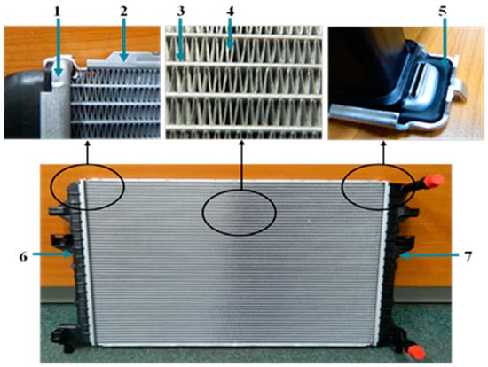
Figure 1.
Car radiator: 1—header plate, 2—reinforcement, 3—tube, 4—fin, 5—gasket (between tank and header plate), 6—return tank, 7—inlet/outlet tank.
- -
- The inlet/outlet tank—the tank into which the coolant flows and later flows out of; applies to U-flow radiators;
- -
- The return tank—the tank through which the flowing coolant returns;
- -
- The radiator core—the main part of the radiator, which consists of tubes and plates enabling the flow of the coolant and increasing the heat exchange area. Additionally, it is made of header plates and reinforcements on the sides;
- -
- The gasket—the seal between the tank and the header plate.
The average combustion temperature of the fuel–air mixture is 1000 °C, while the maximum is approximately 2200 °C. The heat from the engine pistons is dissipated to prevent it from reaching the melting point or deteriorating of mechanical properties. The main function of car radiators is to reduce the temperature of the coolant, which is supported by the air flow. As a result of this process, the temperature of the coolant decreases to bring the engine to the optimal operating temperature of 90 °C [27].
Car radiators must meet the requirements set out in the European Union regulations in the EU directive CSN EN 1148 [28]. One of the most important criteria for assessing car radiators is tightness. Heat exchangers with a specified operating pressure should be tight at a pressure higher than 50 kPa from the pressure to which the plug spring is set. Car radiators are exposed to vibrations and mechanical forces when driving a car, which explains the importance of the mechanical strength. In addition, car radiators should effectively dissipate the heat generated by the engine. High engine speeds increase the operating temperature of car radiators, which are required to resist heat. The operating environment of car radiators, such as atmospheric factors and chemical components of coolants, also require them to be highly resistant to corrosion.
Two types of gaskets in car radiators can be distinguished: (a) dry-applied gasket in the header plate grooves, followed by assembly of the tank; (b) liquid-applied gasket to the tank, and after vulcanization, these parts are assembled with the radiator core.
The gasket placed on the radiator tank should have a good thermal resistance. Due to the working environment of car radiators, the resistance to chemicals present in the cooling system, such as glycol, is important. These requirements are met by the two-component silicone gasket LSR 3286/50. This material is characterized by self-lubricating properties related to the fluid released during vulcanization. Table 1 presents the properties of the mixture containing the base component and the hardener in a 1:1 ratio, vulcanized for 10 min at 175 °C.

Table 1.
The gasket parameters [29].
The gasket is applied on the PA6 polyamide tank. The tank model with a sealing area is shown in Figure 2.
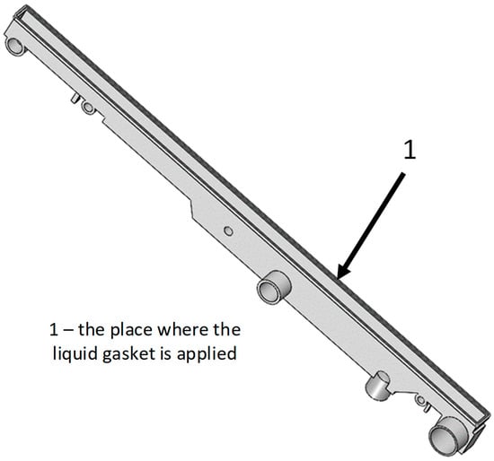
Figure 2.
The tank model made for the simulation purposes.
2.2. Robotic Station
The robotic station was created in the ABB RobotStudio 2022 software, which allows the simulating and testing of various robotic station variants that reflect the real conditions [30].
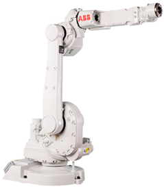
For the simulation application of the liquid gasket to a car radiator tank, the most important stage is the selection of an industrial robot. The main parameters required in the liquid gasket application are: positioning accuracy and repeatability, range, maximum speed, lifting capacity and power consumption. Taking these requirements into account, the IRB 1660ID-4/1.55 robot was selected. Table 2 presents the main parameters of the selected robot [31].
Table 2.
The IRB 1660ID-4/1.55 robot parameters [31].
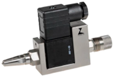
A DLK22LV electromagnetic head was selected to dispense the liquid gasket. The parameters and model are presented in Table 3 [32].
Table 3.
The DLK22LV head parameters [32].
Robotic stations are equipped with the tank containing liquid sealing, the vulcanization oven and the safety fence. Three different variants of robotic stations were analyzed, differing in the way the tank is positioned during the gasket application process: the stationary table, the rotary positioner and the belt conveyor.
2.2.1. First Variant—The Stationary Table
In the construction of robotic stations, a frequently used design solution is the workpiece mounted on the stationary table (Figure 3). All movements necessary to perform the operation are realized by robot arms. The car radiator tank is delivered to the station using the roller conveyor. The IRB1660ID robot with the dedicated gripper places the tank in the mounting holder located on the stationary table. The second robot available at the station is equipped with a dispensing head, which is used to apply the liquid gasket. After the sealing operation is completed, the car radiator tank is placed on a roller conveyor that transports the element to the oven for vulcanization.
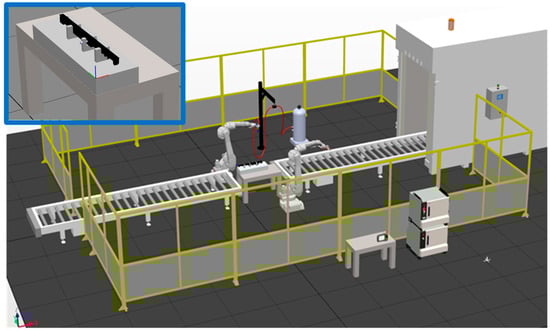
Figure 3.
The robotic station with the stationary table.
2.2.2. Second Variant—The Rotary Positioner
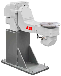
The second variant of the station is equipped with the IRBP A rotary positioner selected from the ABB catalog. The ABB positioners are designed for manipulating workpieces during arc welding, thermal cutting and other applications. All positioner axes can be fully coordinated with the robot. The application of the roller conveyor allows for the automated transport of the car radiator tank to the sealing station and to the oven for vulcanization. The operation of applying the liquid gasket differs from the first variant in that some of the movements necessary to perform the process are performed by the positioner, thus reducing the number of the robot movements. Table 4 shows the parameters of the positioner, while Figure 4 presents the car radiator tank mounted in the rotary positioner.
Table 4.
The IRBP A rotary positioner parameters [33].
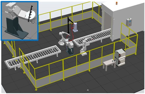
Figure 4.
The robotic station with a rotary positioner.
2.2.3. Third Variant—The Belt Conveyor
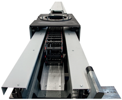
The third robotic station is equipped with the IRBT 2005 belt conveyor (Figure 5) selected from the ABB catalog. The tank delivered to the station via the roller conveyor is placed in the mounting holder by the IRB1660ID robot equipped with the gripper. The second robot available at the station, equipped with the dosing head, is used to apply the liquid gasket. After applying the gasket to the tank, the roller conveyor ensures its further transport to the vulcanization oven. Similarly to the second variant, the auxiliary movement when applying the liquid gasket is performed by the positioner, in this case by the roller conveyor. Table 5 presents the parameters of the selected conveyor [34].
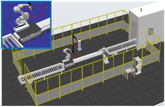
Figure 5.
The robotic station with the conveyor.
Table 5.
The parameters of the IRBT 2005 belt conveyor [34].
2.3. The Movement Trajectory and Program Code Parameters
Figure 6 shows the movement trajectory of the tool center point (TCP) during the liquid gasket application process. The movement of the dosing head starts from the home position, then passes to the dispensing start point and dispenses the gasket along the programmed trajectory related to the tank geometry and finally ends the dispensing and returns to the home position. The TCP movement trajectory was designed in a similar way for all three robotic station variants.
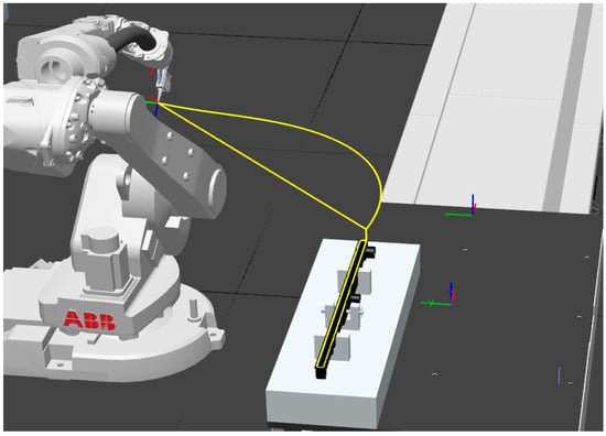
Figure 6.
The TCP trajectory.
In order to develop the robot control code, the ABB RobotStudio 2022 software was used, in which industrial robots can be programmed in the RAPID language. The ABB RobotStudio software is used for modeling, programming and simulating the robot work, both online and offline. The program in the RAPID language consists of instructions describing the robot’s operation, which specify the robot’s movement and output settings. The description of the sample program syntax is presented in Table 6.
Table 6.
The parameters of the IRBT 2005 belt conveyor [34].
In the station with the stationary table, the gasket is applied on a stationary tank, while in the station with the rotary positioner and conveyor, the gasket is applied on the movable tank.
2.4. The Principles of Assessment and Comparison of the Robotic Process
The simulation comparisons were performed in the ABB RobotStudio 2022 software. The Signal Analyzer module was used as a tool for displaying and analyzing signals from the robot controller. This provides the ability to analyze the process time and various types of signals such as sensor data, joint positions, speeds and energy consumption. These signals were analyzed to compare the three designed robotic stations.
In order to analyze the trajectory of applying the liquid gasket and the robot’s free movement trajectory, the TCP Trace function was used, which is a module intended to illustrate the TCP movement trajectory.
Three robotic station variants were selected for the analysis of the energy consumption (stationary table, rotary positioner and conveyor). There could be more robotic station variants, but the aim of this work is to present the energy savings and directions of development for the commonly used methods of positioning an object during the robotic processes.
Figure 7 shows the algorithm for designing a robotic process from the sustainable development and energy efficiency points of view.
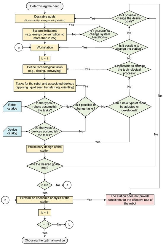
Figure 7.
The algorithm for designing the sustainable production process.
3. Results and Discussion
The RobotStudio program allows for the mapping of the actual movements of the robot and the operation of the equipment elements of the robotic station. Additionally, collision detection has been introduced to notice the dangerous zones.
Simulations were carried out for a constant positioning zone z0 and with a change in the robot’s TCP movement speed in the range of v50–v500 mm/s. The variants of robotic stations with the corresponding simulation time results for the three tank mounting types are presented in Table 7. The comparison includes the percentage change in time when using the rotary positioner and the conveyor compared to the station with the stationary table. Figure 8 visualizes the time comparisons of the robotic station variants.
Table 7.
The simulation times at positioning zone z0.
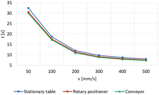
Figure 8.
The comparison of the time for three variants of robotic station.
Increasing the robot movement speed from 50 [mm/s] to 100 [mm/s] resulted in an almost double reduction in the simulation time. Quadrupling the speed did not result in a four-fold reduction in the simulation time. Successive increases in movement speed did not result in such a significant reduction in simulation time. The shortest time was obtained for the highest robot movement speed. Obviously, increasing the robot’s TCP speed reduces the process time. Further increasing the speed is not recommended due to the risk of deterioration of the quality of the gasket application. Taking the first variant as a reference, it can be noted that the greatest reduction in the simulation time for the rotary positioner occurred at a speed of 300 [mm/s] and for the belt conveyor at 400 [mm/s]. The average simulation time reduction for the rotary positioner is 6.31% and for the belt conveyor is 9.03%. In all tests, the conveyor belt had the shortest simulation times.
The energy consumption comparison was obtained using the Signal Analyzer function available in the ABB RobotStudio 2022 software. The results were analyzed for the three robotic stations with the constant robot positioning zone z0 and variable working speed, and these are summarized in Table 8. The obtained energy consumption results of the process simulations are visualized in Figure 9, Figure 10 and Figure 11 as a function of time for the following variants of the station: the stationary table, the rotary positioner and the conveyor. Figure 12 shows the total energy consumption for all tested simulation variants.
Table 8.
The energy consumption for the three robotic stations.
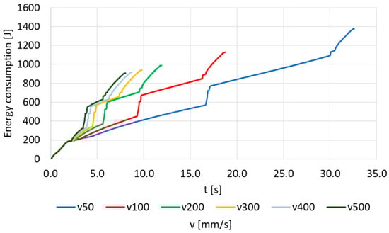
Figure 9.
The energy consumption—the stationary table station.
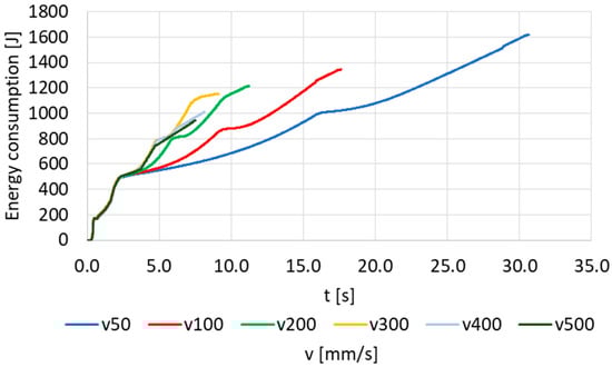
Figure 10.
The energy consumption—the rotary positioner.
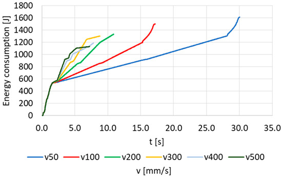
Figure 11.
The energy consumption—the conveyor.
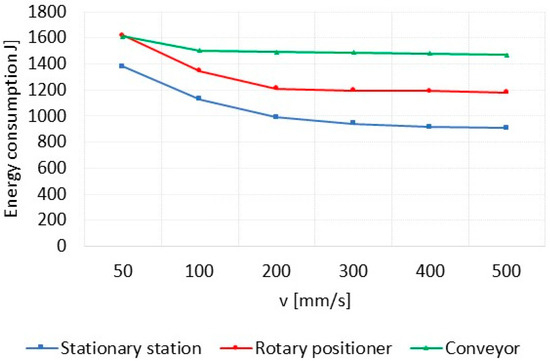
Figure 12.
The summary of the total energy consumption.
The energy consumption analyses take into account the work of the robot, but also the work of the rotary positioner and the conveyor. Analyzing the obtained results of the energy consumption, it can be seen that for the lowest speed value the energy consumption is the highest. Increasing the speed of the movement reduces the energy consumption, which is the lowest for the highest robot speed. Taking the energy expenditure at a speed of 50 [mm/s] as a reference, the variant with a stationary table achieved the greatest reduction in the energy consumption to 34.09%, while the lowest reduction had the station variant with the belt conveyor which amounted to 8.75%. It can also be noticed that from a speed of 400 [mm/s] the energy consumption begins to stabilize. The average reduction in the energy consumption for the station with the stationary table was 29.15 [J], for the variant with the rotary positioner it was 24.23 [J] and for the variant with the belt conveyor it was 7.74 [J]. In all tests, the belt conveyor had the highest value of energy consumption, which for the speed of 500 [mm/s] was 162% of the energy consumption when compared to the station with the stationary table.
In addition to the analysis of process time and energy consumption, cost calculations for each of the three robotic station variants were considered important. The results of the cost analysis are presented in Table 9.
Table 9.
The cost calculations for the three robotic stations.
The lowest process times were obtained for the station variant with the belt conveyor. It is also the most energy-intensive process. Comparing the costs, such as cost of 1 piece and 1 kWh, it is possible to conclude that despite the most energy-intensive process, it brings the highest profits due to the largest number of gaskets made. As the energy prices increase, the profit of the conveyor belt variant decreases.
4. Conclusions
The energy consumption of robotic production processes is important from the point of view of increasing the efficiency and reducing the production costs, as well as increasing the life cycle of industrial robots through the economical use of energy. The selection of energy-saving devices supporting the robot’s operation, such as positioners or conveyors, is crucial. However, existing technological equipment can also be optimized energetically by modifying the trajectory or the robot movement parameters.
The novelty of this research is the practical analysis of the energy consumption by a robotic station in real production conditions. The influence of robot motion parameters on the energy consumption was also determined. The research results and analyses presented in this manuscript can be helpful in other robotic manufacturing processes in which the implementation of sustainable development assumptions is considered.
Analysis in a virtual simulation environment has many benefits. It is possible to control information about: process time, energy consumption, signal operation or movement speed. These data are important during design (selection of a robot, positioner or other equipment) and robotic stations programming.
In the first stage of this research including the positioning zone z0, a number of simulations were carried out with changes in robot movement speed. Increasing the speed to 100 [mm/s] resulted in an almost two-fold reduction in the simulation time. Quadrupling the speed did not result in a four-fold reduction in the simulation time. In all tests, the conveyor belt had the shortest simulation times. Performing a robotic task on a moving object reduces the process time.
Increasing the speed of movement reduces the energy consumption, which is the lowest at the highest speed. From a speed of 400 [mm/s] the energy consumption begins to stabilize. In all tests, the belt conveyor had the highest value of the energy consumption, which for a speed of 500 [mm/s] was 162% of the energy consumption when compared to the station with the stationary table.
It can be concluded that the optimal speed is in the range of 400–500 [mm/s]. In the range of these speeds, no significant reduction in the process time or the energy consumption is observed compared to the previously considered lower speed values. For this reason, higher speeds were not tested and the range of 400–500 mm/s was considered optimal. Moreover, increasing the speed does not translate into other process efficiency parameters, because the distances between the programmed points of the robot’s movement path are too small, and therefore the robot could not achieve the declared movement speed.
The most energy-intensive process (station with the belt conveyor) brings the highest profits due to the largest number of gaskets made. When designing robotic processes, sustainability is important. It is important to consider the greatest possible benefits for the company while taking into account the energy efficiency.
The obtained results are characterized by high universality and can be helpful in assessing other technological processes in which sustainable development is important. In further studies, the exact costs of building each station variant should be considered, as they can have a significant impact on the profitability of the robotization process and the selection of the final solution.
Future research work should be aimed at minimizing the energy consumption of the manufacturing processes, maximizing the production efficiency, while maintaining the appropriate level of the product quality. The use of artificial intelligence algorithms for the energy consumption optimization tasks in real production processes seems to be a current and still insufficiently discussed topic in the scientific literature. These studies, presented in this manuscript, discuss important issues of the energy efficiency in robotic processes and constitute the basis for further research work.
Author Contributions
Conceptualization, K.P. and A.P.; methodology, K.P. and A.P.; software, K.P., M.W. and A.P.; validation, K.P., M.W. and A.P.; formal analysis, K.P., M.W., A.P. and O.C.; investigation, K.P., M.W., A.P. and O.C.; resources, K.P., M.W., A.P. and O.C.; data curation, K.P., M.W. and A.P.; writing—original draft preparation, K.P., M.W., A.P. and O.C.; writing—review and editing, K.P., M.W., A.P. and O.C.; visualization, K.P., M.W., A.P. and O.C.; supervision, K.P. and O.C.; funding acquisition, K.P., M.W. and O.C. All authors have read and agreed to the published version of the manuscript.
Funding
The research was funded by the Polish Ministry of Science and Higher Education as a part of research subsidy, project number: 614/SBAD/1565.
Institutional Review Board Statement
Not applicable.
Informed Consent Statement
Not applicable.
Data Availability Statement
The data presented in this study are available on request from the corresponding author.
Conflicts of Interest
The authors declare no conflicts of interest.
References
- Du, L.; Lin, W. Does the application of industrial robots overcome the Solow paradox? Evidence from China. Technol. Soc. 2022, 68, 101932. [Google Scholar] [CrossRef]
- Lim, W.S.; Dharmawan, A.G.; Soh, G.S. Development and performance evaluation of a hybrid-wire arc additive manufacturing system based on robot manipulators. Mater. Today Proc. 2022, 70, 587–592. [Google Scholar] [CrossRef]
- Ciszak, O.; Juszkiewicz, J.; Suszyński, M. Programming of industrial robots using the recognition of geometric signs in flexible welding process. Symmetry 2020, 12, 1429. [Google Scholar] [CrossRef]
- Dzedzickis, A.; Subačiūtė-Žemaitienė, J.; Šutinys, E.; Samukaitė-Bubnienė, U.; Bučinskas, V. Advanced applications of industrial robotics: New trends and possibilities. Appl. Sci. 2022, 12, 135. [Google Scholar] [CrossRef]
- Muzan, I.W.; Faisal, T.; Al-Assadi, H.M.A.A.; Iwan, M. Implementation of industrial robot for painting applications. Procedia Eng. 2012, 41, 1329–1335. [Google Scholar] [CrossRef]
- Solvang, B.; Sziebig, G.; Korondi, P. Multilevel control of flexible manufacturing systems. In Proceedings of the 2008 Conference on Human System Interactions, Krakow, Poland, 25–27 May 2008; pp. 785–790. [Google Scholar]
- Li, J.; Barwood, M.; Rahimifard, S. Robotic disassembly for increased recovery of strategically important materials from electrical vehicles. Robot. Comput. Integr. Manuf. 2018, 50, 203–212. [Google Scholar] [CrossRef]
- Müller, C. World Robotics 2023—Industrial Robots; IFR Statistical Department, VDMA Services GmbH: Frankfurt am Main, Germany, 2023. [Google Scholar]
- Torresen, J. A Review of Future and Ethical Perspectives of Robotics and AI. Front. Robot. AI 2018, 4, 75. [Google Scholar] [CrossRef]
- Emaminejad, N.; Akhavian, R. Trustworthy AI and robotics: Implications for the AEC industry. Autom. Constr. 2022, 139, 104298. [Google Scholar] [CrossRef]
- Gui, W.; Zhou, F.; Tang, F. Research on Motion Simulation of Stacking Robot Workstation Based on RobotStudio. In Proceedings of the 2023 IEEE 3rd International Conference on Power, Electronics and Computer Applications, ICPECA 2023, Shenyang, China, 29–31 January 2023; Institute of Electrical and Electronics Engineers Inc., 2023; pp. 301–305. [Google Scholar]
- Peta, K.; Wlodarczyk, J.; Maniak, M. Analysis of trajectory and motion parameters of an industrial robot cooperating with a numerically controlled machine tools. J. Manuf. Process. 2023, 101, 1332–1342. [Google Scholar] [CrossRef]
- Li, L.Y.; Long, Y.; Wang, T.Q.; Yue, J.F.; Meng, Q.Y. Operation space trajectory planning of welding robot based on rational B-splines curve. J. Tianjin Polytech. Univ. 2015, 34, 80–83. [Google Scholar] [CrossRef]
- Duan, H.F.; Han, W.; Chen, X.B.; Yang, A. Design of Grinding Robot Workstation for Automotive Water-Cooled Casing Castings. Zhuzao/Foundry 2023, 72, 607–611. [Google Scholar]
- Li, G.; Li, Y.; Han, H. The Simulation Design of Robot Automatic Sorting and Palletizing Workstation Based on RobotStudio. In Proceedings of the 2022 5th International Conference on Robotics, Control and Automation Engineering, RCAE 2022, Changchun, China, 28–30 October 2022; Institute of Electrical and Electronics Engineers Inc., 2022; pp. 205–208. [Google Scholar]
- Gupta, R.S.P.K.A. Simulation of Robotized Mig Welding Using Robotstudio. Int. J. Sci. Res. 2014, 3, 523–528. [Google Scholar]
- Fang, D.; Zheng, Y.; Zhang, B.; Li, X.; Ju, P.; Li, H.; Zeng, C. Automatic robot trajectory for thermal-sprayed complex surfaces. Adv. Mater. Sci. Eng. 2018, 2018, 8697056. [Google Scholar] [CrossRef]
- Harsha Arigela, S.; Kumar Chintamreddy, V. Fused deposition modeling of an aircraft wing using industrial robot with non-linear tool path generation. Int. J. Eng. Trans. A Basics 2021, 34, 272–282. [Google Scholar] [CrossRef]
- Jayal, A.D.; Badurdeen, F.; Dillon, O.W.; Jawahir, I.S. Sustainable manufacturing: Modeling and optimization challenges at the product, process and system levels. CIRP J. Manuf. Sci. Technol. 2010, 2, 144–152. [Google Scholar] [CrossRef]
- Giannetti, B.F.; Agostinho, F.; Eras, J.J.C.; Yang, Z.; Almeida, C.M.V.B. Cleaner production for achieving the sustainable development goals. J. Clean. Prod. 2020, 271, 122127. [Google Scholar] [CrossRef]
- Gadaleta, M.; Pellicciari, M.; Berselli, G. Optimization of the energy consumption of industrial robots for automatic code generation. Robot. Comput. Integr. Manuf. 2019, 57, 452–464. [Google Scholar] [CrossRef]
- Liu, A.; Liu, H.; Yao, B.; Xu, W.; Yang, M. Energy consumption modeling of industrial robot based on simulated power data and parameter identification. Adv. Mech. Eng. 2018, 10, 1687814018773852. [Google Scholar] [CrossRef]
- Paes, K.; Dewulf, W.; Elst, K.V.; Kellens, K.; Slaets, P. Energy Efficient Trajectories for an Industrial ABB Robot. Procedia CIRP 2014, 15, 105–110. [Google Scholar] [CrossRef]
- Gadaleta, M.; Berselli, G.; Pellicciari, M.; Sposato, M. A Simulation Tool for Computing Energy Optimal Motion Parameters of Industrial Robots. Procedia Manuf. 2017, 11, 319–328. [Google Scholar] [CrossRef]
- Soori, M.; Arezoo, B.; Dastres, R. Optimization of energy consumption in industrial robots, a review. Cogn. Robot. 2023, 3, 142–157. [Google Scholar] [CrossRef]
- Peta, K.; Zurek, J. Prediction of air leakage in heat exchangers for automotive applications using artificial neural networks. In Proceedings of the 2018 9th IEEE Annual Ubiquitous Computing, Electronics & Mobile Communication Conference (UEMCON) 2018, New York, NY, USA, 8–10 November 2018; pp. 721–725. [Google Scholar] [CrossRef]
- Azelee, N.I.W.; Manas, N.H.A.; Hanapi, S.Z.; Sarip, S.H.M.; Malek, R.A.; El-Enshasy, H.A.; Dailin, D.J.; Ngah, M.F. Removal of pesticides from water and wastewater by agricultural biomass-based adsorbents. In Pesticides Remediation Technologies from Water and Wastewater; Elsevier: Amsterdam, The Netherlands, 2022; pp. 365–384. [Google Scholar] [CrossRef]
- BN EN 1148:1999/A1:2005; Heat Exchangers—Water to Water Heat Exchangers for District Heating—Test Procedures for Establishing the Performance Data. The British Standards Institution (BSI): London, UK, 2005.
- Silopren™ LSR 3286 50 TP4224. Available online: https://www.momentive.com/pt-br/products/tds/silopren-lsr-3286-50-tp4224?productid=5d21322e-a53f-48f9-9319-9d4675dfffc8 (accessed on 21 November 2023).
- RobotStudio Suite|ABB. Available online: https://new.abb.com/products/robotics/robotstudio (accessed on 21 November 2023).
- IRB 1660ID|ABB Robotics—Articulated Robots Portfolio. Available online: https://new.abb.com/products/robotics/robots/articulated-robots/irb-1660id (accessed on 21 November 2023).
- Electromagnetic Valve DLK22LV. Available online: https://www.zator.it/wp-content/uploads/2021/05/Datasheet-DLK22LV_V02_eng.pdf (accessed on 21 November 2023).
- IRBP-A Industrial Robot Positioner|ABB. Available online: https://library.e.abb.com/public/fed2591c8edc41c19f1b61deb0ce15e5/IRBP-A_datasheet_ROB10080EN_RevB.pdf?x-sign=o0eGF6H+QNeBjZ63VRMLxqyBjmaUkE78Fu78m7wYUDqXzXJOzIPmCPmm3b0BexS4 (accessed on 21 November 2023).
- IRBT 2005 Track Motion|ABB. Available online: https://new.abb.com/products/pl/3HAC051479-001/irbt-2005-track-motion (accessed on 21 November 2023).
Disclaimer/Publisher’s Note: The statements, opinions and data contained in all publications are solely those of the individual author(s) and contributor(s) and not of MDPI and/or the editor(s). MDPI and/or the editor(s) disclaim responsibility for any injury to people or property resulting from any ideas, methods, instructions or products referred to in the content. |
© 2024 by the authors. Licensee MDPI, Basel, Switzerland. This article is an open access article distributed under the terms and conditions of the Creative Commons Attribution (CC BY) license (https://creativecommons.org/licenses/by/4.0/).