Abstract
Part of the Hang-Tai High-speed Railway (Hangzhou via Shaoxing to Taizhou in Zhejiang Provence) in China passes through the diatomaceous earth area, which is the first time in the history of Chinese high-speed railway construction. This type of soil has significant compressibility, swelling and disintegration. Diatomaceous earth also shows a sharp reduction in strength when exposed to water, which severely impacts the safety of the project. However, no studies have been carried out on the engineering practice of building a high-speed railway in the diatomaceous earth area in China. Moreover, there is limited experience in the construction of ballastless track through the diatomaceous earth area. In order to ensure the stability of the high-speed railway subgrade in diatomaceous earth area, and considering the high level of precipitation in the location of this railway, a kind of waterproof and drainage subgrade (WDS) is proposed to reduce the influence of precipitation on the strength of the diatomaceous earth foundation. The subgrade has a flexible waterproof and drainage layer (WDL) inside, which consists of capillary waterproof and drainage plates and medium-coarse sand. In the present study, field tests including immersion tests and excitation test are carried out on a subgrade test section to verify the subgrade structure. The tests mainly focus on construction technology, waterproof performance and dynamic characteristics. The studies show that the subgrade bed with the WDL can effectively avoid the diatomaceous earth foundation from rainfall interference and maintain the long-term stability of the subgrade. The flexible WDL in WDS has a significant energy dissipation effect in comparison with the traditional subgrade (TS) filler and can play a key role in vibration damping, promoting the attenuation of dynamic response in the downward and cross-sectional directions within the subgrade. The dynamic response of the WDS attenuates along the depth. In comparison with the existing high-speed railway subgrade measured data, its dynamic response attenuation coefficient is within acceptable limits. The laying of the WDL does not change the subgrade dynamic characteristics transfer law. The proposed structure meets the requirements of ballastless track construction for high-speed railways, and the WDL can be used in the design of high-speed railways for enhanced drainage protection in diatomaceous soil areas or other special soil areas.
1. Introduction
Ballastless track is widely used in high speed railways in Germany, Japan and China due to its outstanding advantages such as its consistency of track geometry for long periods and its significant reduction in maintenance and repair [1,2,3]. Hang-Tai High-speed Railway also uses ballastless track (CRTS double-block), and it is the first high-speed railway to cross the diatomite region in China. As one of the important lower foundation types for high-speed railways, the performance of the subgrade bed is important for maintaining a smooth and stable ballastless track line. For example, the stiffness and strength of the subgrade bed should meet the elastic deformation and bearing capacity requirements under train load. Moreover, the subgrade bed structure should prevent surface water intrusion which can avoid mud pumping and other damaging consequences. In addition, high-speed railways have strict limitations in the post-construction settlement, such as the Code for Design of High Speed Railway in China. This code stipulates that the ballastless track subgrade post-construction settlement should be controlled within 15 mm and the post-construction differential settlement at the joints between the subgrade and structures such as bridges and tunnels should be less than 5 mm [4]. As per the studies conducted so far, the post-construction settlement of the subgrade is mainly caused by the settlement deformation of the foundation. Hence, a lot of attention is given to the selection and design of high-speed railways to overcome the challenges posed by soft soil and other special soil in ensuring the stability of the subgrade and for meeting the settlement deformation control requirements. However, diatomaceous earth has high compressibility, obvious swelling and disintegration characteristics, and its strength is obviously reduced in the case of water [5,6]. There is no precedent for railway construction in China in diatomaceous earth areas, and there is a lack of field tests and construction experience in such terrain. Therefore, the special engineering characteristics of diatomaceous earth are a great challenge for the Hangtai high-speed railway subgrade, which has strict settlement control requirements.
Diatomaceous earth is a kind of special earth formed by diatom shells interspersed with other minerals such as montmorillonite, illite and kaolinite after prolonged deposition. The properties of diatomaceous earth are closely related to its formation and internal structure, type of diatoms, mineral composition and their constituents [7,8]. This earth contains the diatom shells which are the outer cell-walls left behind after the decay of the internal matter of the diatoms. Diatomaceous earth generally has high porosity, low dry density, high water content and high compressibility [5,8,9]. Previous studies on diatomaceous earth mainly focused on its physical and mechanical properties. However, limited studies have been carried out on its engineering properties and effects. It is rare to observe large-scale line construction in China in diatomaceous earth areas. One of the exceptions to this general trend is the highway construction in the Tengchong area of Yunnan Province. Evidence shows that the diatomaceous earth in Yunnan Province has the characteristics of both diatomaceous earth and expansive earth, which is characterized by high porosity, strong water absorption, high plasticity and obvious disintegration characteristics, and is an extremely complex regional special soil [6,9]. It can also shrink or swell under alternating wet and dry conditions, leading to geological disasters such as landslides, which need special attention during waterproof and drainage design of real-time projects [10]. As a result, waterproof and drainage measures should be taken for high-speed railway subgrades in diatomaceous earth areas.
At present, there are two main types of subgrade waterproof and drainage structures:
- The structure laid on the surface of the subgrade as shown in Figure 1a, such as:
 Figure 1. Different types of subgrade waterproof and drainage structures: (a) the structure laid on the surface of the subgrade; (b) the structure laid between the bottom layer of the subgrade bed layer and the foundation of the subgrade; (c) the structure laid in the bottom of surface layer of the subgrade; (1) surface layer of subgrade bed; (2) bottom layer of subgrade bed; (3) foundation; (4) waterproof and drainage structure.
- Polyurethane gravel waterproof seal layer [11];
- Full-section asphalt concrete waterproof sealing layer [12];
- Mastic asphalt waterproof layer for high-speed railways in cold areas [13], etc.
- The structure laid within the subgrade as shown in Figure 1b,c, such as:
- Fully enclosed subgrade waterproof and drainage composite structure, composed of geogrid and fiber glass fabric, laid between the bottom layer of the subgrade bed layer and the foundation of the subgrade [14];
- The waterproof and drainage structure consisting of three-dimensional earthwork mesh geotextile, laid in the bottom of surface layer of the subgrade bed [15];
- Semi-rigid waterproof structure made of modified cement-based composite waterproof material, laid in the bottom of surface layer of the subgrade bed [16].
Of the above measures, those relating to materials usually require strict composition ratios and specialized construction equipment. In addition, the waterproof and drainage structure composed of geotextiles has the characteristics of untimely drainage and poor durability.
The capillary waterproof and drainage plate (CWDP) is a kind of high-density PVC polymeric material, with good toughness, acid and alkaline resistance, durability and anti-clogging capability [17,18]. It has capillary grooves on its surface, which have a capillary effect and allow the water in the soil to drain quickly. It is simple and quick to apply in engineering and is commonly used in the design of waterproof and drainage for roadbed, tunnels, gardens and other buildings [19,20,21,22]. Based on these advantages of the CWDP, a new waterproof and drainage subgrade bed structure based on the CWDP was proposed, fully considering the high standards set for the construction of high-speed railways and the strong waterproof and drainage requirements of a diatomaceous earth subgrade. In addition, a test section of the diatomaceous earth subgrade was selected to carry out corresponding field tests to study its waterproof performance and dynamic characteristics, which could, with respect to the Hang-Tai High-speed Railway, provide the necessary technical support for the construction of a railway through the diatomaceous earth area.
2. Overview of Hang-Tai High-Speed Railway
The Hang-Tai High-speed Railway is located in the eastern central region of Zhejiang Province, China, with a total line length of 226.369 km. The high-speed railway is connected to Shaoxing North Station from the Hangzhou-Ningbo Passenger Dedicated Railway, passing through Shaoxing City, Taizhou City and other districts and counties into Wenling City, and then connecting to the Wenling Station of the Yong-Tai-Wen Railway (Ningbo-Taizhou-Wenzhou Railway). There are eight stations on the way, namely, Shaoxing North Station, Shangyu South Station, Shengzhou North Station, Shengzhou-Xinchang Station, Tiantai Mountain Station, Linhai Station and Wenling Station. It is designed for operational speed of 350 km/h on CRTS double-block ballastless track. Geological investigations have discovered huge diatomite presence in the basaltic area of Shengzhou and Xinchang County. The diatomite is distributed in the basaltic rocks and the layers of fluvio-lacustrine sediments. It is mainly divided into white diatomite, blue diatomite and black diatomite in layers ranging from 4 to 90 m thick. Among these three types of diatomite, black diatomite has the highest water content (67.47%), liquid limit (81.1%), and void ratio (1.63), and white diatomite has the highest compressibility coefficient (0.42 MPa−1), uniaxial saturated compressive strength (0.99 MPa), free swelling ratio (59.2%) [23]. It can be seen that the diatomaceous earth is characterized by high porosity and compressibility. In addition, it is easy softening and disintegration when exposed to water, resulting in a sharp decline in its engineering properties [24]. In particular, the white diatomaceous earth is susceptible to alternating wet and dry conditions due to the influence of moisture. Its mechanical properties drop sharply due to the changes of soil structure caused by construction and alternating wet and dry conditions, which can easily cause damage to the primary structure and thus a loss of structural strength [25]. It may also lead to shear displacement within. It is to be noted here that the engineering properties of white diatomaceous earth are the worst among the three types of diatomaceous earth [26]. During the Hang-Tai High-speed Railway route selection, the subgrade had to pass through the diatomaceous earth area for a length about 3 km because of the location of stations.
The region of diatomaceous earth that the Hang-Tai High-speed Railway passes through is located in an area with a subtropical monsoon climate. There are two rainy periods throughout the year, March to June and September, and the rest of the year is the low raining season. March to April is the spring rainy season, with monthly precipitation of 240~277 mm. May to June is the plum rain season (the climatic phenomenon of continuous cloudy days with rainfall), with monthly precipitation of 348~377 mm. September is the typhoon season, with precipitation of 130~190 mm. The average annual rainfall in this region is around 1301~1465 mm.
Combining the engineering characteristics of diatomaceous earth and the climate and geological conditions along the Hang-Tai high-speed railway, it is clear that an efficient drainage design plays a vital role for the subgrade in the diatomaceous earth area of the Hang-Tai High-speed Railway. If no engineering treatment is carried out, when water penetrates into the diatomaceous earth foundation of the High-speed Railway, it will inevitably cause a softening of the diatomaceous earth and a sinking of the foundation under the combination of wet and dry cycles and the dynamic loading of the upper trains, which will have an impact on the safety of the high-speed railway operation [27,28,29]. Therefore, the new WDS based on CWDP is proposed and it was tested in the diatomaceous earth test section.
3. Waterproof and Drainage Subgrade Bed
Based on the characteristics of diatomaceous earth and also the fact that this is the first time it is being subjected to high-speed railway operations in China, in the present study, the WDL consisting of capillary waterproof and drainage plates (CWDPs) was added to the cutting bed design for improving the waterproof performance and avoiding water penetration into the cutting bed and the diatomaceous earth foundation. The overall structure of the diatomaceous earth subgrade is shown in Figure 2. The cutting bed is laid on the pile raft. Its layers are, in descending order, 40 cm graded gravel, 20 cm coarse-grained filler, 20 cm WDL and 80 cm coarse-grained filler. The WDL is located 0.2 m below the bottom of the surface layer of the subgrade bed and consists of two layers of 10 cm medium coarse sand. The WDL consists of two layers of 10 cm thick medium-coarse sand interspersed with a layer made of waterproof and drainage plates. The particle diameter of medium-coarse sand is less than 5 mm, and the grain size distribution is shown in Table 1. Waterproof and drainage plates are CWDPs with dense grooves along the longitudinal direction, resulting in the capillary effect, as shown in Figure 3a,b, and its performance is shown in Table 2. Due to the existence of grooves on the surface of the CWDPs, the water channel is formed. Compared with the traditional waterproof geomembrane, its drainage effect is more obvious. When the bottom coarse-grained filler is filled to the design height, a layer of 10 cm medium-coarse sand is first laid on top of it and rolled. After acceptance, the laying of the CWDPs is started. The plates are laid horizontally along the line, keeping the side with the drainage grooves upwards, as shown in Figure 3c, in order to allow the water seepage from the surface of the subgrade to drain along the grooves towards the subgrade and beyond. At the same time, the adjacent plates are laid in sequence, with the lapped edges stacked above and below each other and completely covered, and the WDL is set at a 4% slope along the cross-sectional plane of the subgrade.
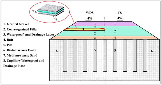
Figure 2.
Waterproof and drainage subgrade and traditional subgrade diagram.

Table 1.
Grain size distribution.
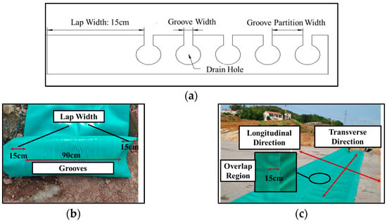
Figure 3.
CWDP and construction: (a) detailed drawing of grooves; (b) CWDP; (c) the construction of WDL.

Table 2.
Performance of CWDP.
The waterproof and drainage structure proposed in this study is different from the rigid structure mentioned by Wang and Yang [30]. The setting of WDL will inevitably affect the dynamic transfer characteristics of the subgrade. Therefore, considering the safety of high-speed railways, it is necessary to study its dynamic characteristics and variation laws under the action of dynamic train loads. Through the field testing of dynamic characteristics under a varying service environment, the variation laws of dynamic stress and acceleration along the depth of the subgrade are obtained to evaluate the dynamic stability of the subgrade. In order to understand the performance of the WDS better, a TS section is also selected for comparison tests. The research methodology for this study is presented in Figure 4.
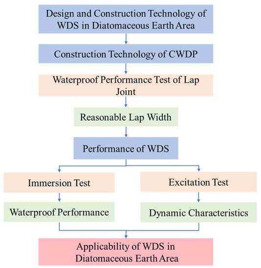
Figure 4.
Schematic diagram of the research methodology.
4. Waterproof Tests on WDS
The main structure that acts as a waterproof and drainage layer is the CWDP layer. Due to the limited width of the plates, it is necessary to lap several pieces in sequence to form a layer when used over long distances and large areas. If the lap is large, this will lead to increased raw material usage and construction costs, while if the lap is small, there is a risk of water penetration. In this test, a 15 cm lap area was set for the plates and then the waterproofing performance of the lap joint was tested to verify the effectiveness of the lap width. Immersion test was carried out on the WDS in a submerged condition to obtain changes in the water content of the subgrade at different locations and for evaluating the effectiveness of the waterproof and drainage performance. The flowchart of the immersion test is shown in Figure 5.
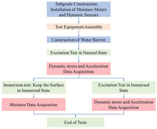
Figure 5.
The flowchart of tests.
4.1. Waterproof Performance Test of CWDP Lap Joints
4.1.1. Test Program
As the main purpose of this test is only to test the waterproofing effect of the lap joint, the coarse sand was replaced by fine sand during the test. As per the WDL design, the waterproof performance of the CWDPs lap joint is tested as shown in Figure 6, which consists of a 10 cm layer of fine sand interspersed with a layer of CWDPs. To test the waterproof effect of the lap joints, four soil moisture meters (range: 0~100%, precision: ±3%) were inserted under the bottom layer of fine sand, located directly below the lap joints (M1, M2) and on either sides (M3, M4), respectively, to observe the soil moisture meter readings before and after the test. When laying the CWDPs, the 15 cm lap width is fully lapped, and the lap joint is located directly above the soil moisture meter. After the WDL has been laid, water is sprayed on the top fine sand and the surface wetness is maintained throughout the test.
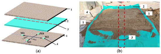
Figure 6.
Waterproof performance test of CWDPs at the lap joint: (a) sensor deployment; (b) model test; (1) fine sand; (2) CWDP; (3) overlap region; (4) soil moisture meter.
4.1.2. Analysis of Immersion Test Results
The variation of readings from the soil moisture meter before and after the test are shown in Figure 7. It could be observed from the figure that the variation in the soil moisture meter readings at the four points is considerably less. A decrease in the soil moisture meter reading was observed at M4 on the side adjacent to the lap joint, which could be attributed to the evaporation of water from the fine sand. The test results show that water did not seep through the lap joints during the test, indicating that the 15 cm CWDP lap width can meet the waterproof requirements of WDL.
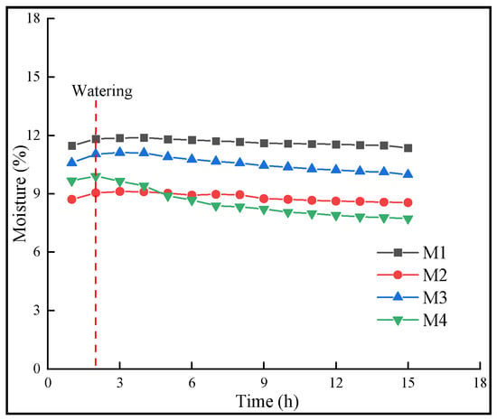
Figure 7.
Soil moisture variation for lap joint test.
4.2. Waterproof and Drainage Performance Tests
4.2.1. Test Setup
The performance test is mainly carried out to verify the waterproof and drainage effect of the WDS for investigating water penetration into the diatomaceous earth foundation during rainfall. In order to simulate the most unfavorable situation due to the impact of rainfall on the subgrade, the tests were carried out by pouring water on the subgrade surface. Various tests on the subgrade test section were conducted from 17 October 2019 to 14 November 2019. The waterproof and drainage performance test set up is shown in Figure 8. In order to ensure that water accumulates on the subgrade surface to form a continuous flooding condition, a water barrier was constructed on the subgrade surface. The water barrier of size 7 m × 4 m × 0.3 m was placed along the cross-section of the subgrade. A waterproof cloth was placed around the water barrier and compacted with fine soil to prevent water seepage through the water barrier. During the test, water was pumped into the water barrier at all times for maintaining the submerged state of the subgrade surface, as water may seep and spread from the soil layer of the subgrade to the surrounding area. For testing purpose, the soil moisture meters (WDM1~WDM6) were used for monitoring the change in soil moisture levels at different locations in the subgrade bed during the test, as shown in left part of Figure 9a. Moreover, for facilitating the comparison of the waterproof and drainage performance of the WDS, a comparison test was carried out on TS, by placing the sensors (TM1~TM6) in test section, as shown in the right side of Figure 9a. A sample photograph of the sensors set up during the field testing is shown in Figure 9b.
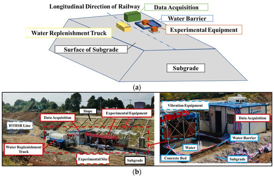
Figure 8.
Waterproof and drainage performance test: (a) schematic diagram of test site; (b) field test diagram.

Figure 9.
Deployment of sensors: (a) sensor deployment; (b) the sensors.
4.2.2. Analysis of Test Results
Figure 10 shows the variations in the soil moisture meter readings at different locations of the WDS and TS beginning from the construction period of the subgrade to the end of the test. The site was going through the rainy season caused by a typhoon during construction. On 1 October 2019, due to Typhoon Mina, the area where the test section was located was under rainstorm, and the cumulative rainfall for 3 h was 51.3 mm in the local part of the city. Because of the heavy rainfall, the water content of the soil at the bottom of the previously completed subgrade bed increased quickly. This resulted in a rapid increase in the soil moisture meter reading at the location 1.6 m below the subgrade surface, as shown in Figure 10 Area I.
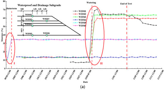
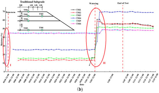
Figure 10.
Moisture changes in the waterproof and drainage performance tests: (a) WDS; (b) TS.
For the WDS, as shown in Figure 10a, the soil moisture meter reading of WDM1 increased abruptly due to the accumulation of pumped water at the subgrade surface. At 0.4 m below the subgrade surface, the sudden increase in moisture observed was slightly later than that observed on the surface due to the deeper position of WDM2 and WDM3. The soil moisture meters were all located above the WDL, and their values attained steady state as the test progressed. The values of soil moisture meters WDM4, WDM5 and WDM6 at the locations below the WDL did not change significantly after the water immersion test, indicating that the WDL provided good isolation from water infiltration and that it was suitable for diatomaceous earth subgrade. For the TS, as shown in Figure 10b, the values of soil moisture meters TM1, TM2 and TM3 increased rapidly at 0.4 m below the surface since the water accumulated at the surface of TS, while the values of soil moisture meters TM4, TM5 and TM6 increased below 0.4 m of the surface due to water seepage into the bottom of subgrade as a result of the absence of the WDL. The most significant increase was seen at TM4. However, the increase in moisture content at TM5 and TM6 was obvious due to the heavy rainfall before the test. This, in turn, reduced effect of the water immersion test on soil moisture content and it can be seen that the increase in moisture content of the soil after the test at the same location is comparatively small.
A comparison of the soil moisture content (WDM4) at 0.2 m below the WDL of the WDS with the corresponding position in the TS (TM4) is shown in Figure 11. It can be seen that the soil moisture at this location in the WDS remained unchanged at around 13% before and after the water immersion test, whereas in the TS, it changed from 25% to 70%. This is indicative of the fact that there was no infiltration of water into the lower layer of the WDL during the water immersion test. However, in the TS, the water infiltrated from the surface to the bottom due to the absence of the WDL.
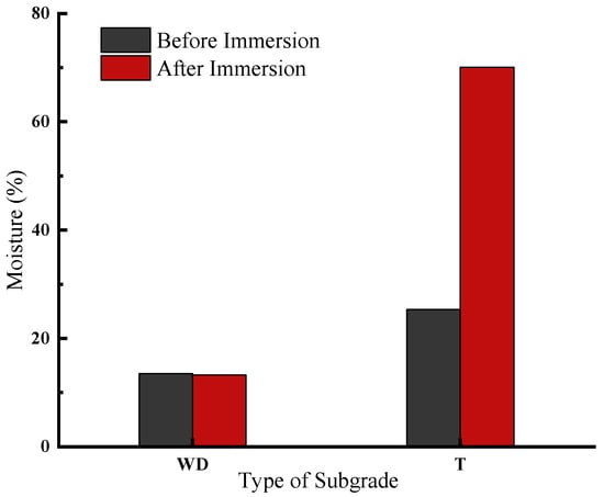
Figure 11.
Comparison of waterproof and drainage performance of WDL.
In order to improve the effectiveness of waterproof and drainage effect testing for WDS, the adjacent side of the subgrade was excavated after the water immersion test, as shown in Figure 12. The coarse-grained filler of the subgrade has good permeability (about 10−6 m/s). This results in rapid infiltration of the water on the surface of the subgrade as soon as the water immersion test begins, further leading to an increase in the wetness of the graded gravel layer, the coarse-grained filler layer and the upper medium coarse sand layer. When the water penetrates into the WDL, a major quantity of water seeps out along the surface of the CWDPs due to its impermeability. As can be seen in Figure 12, the excavated edges of the coarse sand in the upper part have been eroded by the seepage of water, while the coarse sand below the CWDPs has not seen any underwater seepage. No observable change was observed in the moisture content.
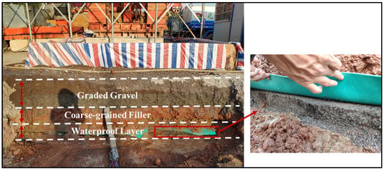
Figure 12.
Seepage on the side of the subgrade after excavation.
The above analysis shows that the moisture content of the soil below the WDL of the WDS remained unchanged before and after the water immersion test. This indicates that the moisture did not seep down through the WDL during the test, and that the WDS has an effective waterproof and drainage performance, which can prevent rainwater from seeping into the diatomaceous earth foundation during rainfall and can maintain the stability of the subgrade.
5. Dynamic Characteristics of WDS
The laying of WDL changes the structure of the subgrade. As the physical and mechanical properties of this layer differ significantly from those of the subgrade filler, there may be differences between the mechanical properties of the WDS and those of the TS. Therefore, it is necessary to carry out excitation tests on WDS under different service conditions (natural and immersed) and to analyze the dynamic transfer characteristics of WDS with the TS in the immersed condition as a control group, thus providing a reference for the design and construction of WDS in diatomaceous earth areas. The flowchart of excitation tests is also shown in Figure 5.
5.1. Experiment
The dynamic characteristics of the subgrade bed were tested under natural and immersed conditions, and under immersed conditions for the traditional subgrade bed, in order to investigate the dynamic characteristics of the WDS under various service conditions. The differences between the WDS and the TS under immersed conditions were also tested. During the tests, the WDS was first excited in its natural state for 2 million cycles, followed by 2 million cycles in the immersed state, while the TS was first excited in its natural state for approximately 0.45 million cycles to simulate the relative stability of the subgrade under the cyclic train loading during operation, followed by 2 million cycles in the immersed state.
The cyclic excitation load Is generated by two eccentric blocks on the excitation equipment rotating in opposite directions. This can simulate the moving train load with cyclic loading, resulting in a sinusoidal curve. The maximum excitation load generated by the eccentric blocks can be calculated using Equation (1):
where m0 is the total mass of the two eccentric blocks, e is the eccentric distance of the eccentric block assembly and f is the motor operating frequency.
According to the Code for Design of High Speed Railway [4], the design dynamic stress of the subgrade bed is calculated as per Equation (2):
where is the speed influence coefficient, considered as 0.003 for train speeds of 300 km to 350 km per hour, P is the static axle weight of the train, considered as 200 kN, and is the impact coefficient, the maximum value for passenger dedicated lines having a value of 1.90.
As per Equation (2), the stress generated by the train through the subgrade consists of two parts: (1) the static stress caused by the self-weight of the line upper structures; (2) the dynamic stress caused by the load of the moving train, as mentioned in Equations (3) and (4).
The analysis shows that and result in dynamic stress of the subgrade for design consideration as . The variation of with time is shown in Figure 13.
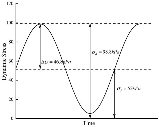
Figure 13.
curve with time.
Corresponding to the field excitation test, the static stress generated by the self-weight of the line upper structure is achieved by the self-weight of the excitation equipment and the lower connected concrete bed. The additional dynamic stress generated by the moving train load is simulated by cyclic variation of vertical dynamic load generated by the eccentric block.
The self-weight of the excitation equipment is 175 kN and the self-weight of the concrete bed underneath is 50.58 kN. Contact area between the concrete bed and the subgrade surface is 1.8 m × 1.8 m. The static stress produced by these at the subgrade surface is . The additional dynamic stress is provided by cyclic variation of vertical load generated by the eccentric block. As can be seen from Equation (1), the excitation force generated by the eccentric block can be adjusted by varying the excitation frequency. During the field tests, it was found that when the excitation frequency is 15 Hz, the dynamic stress on the subgrade surface varied from 38 to 49 kPa. By considering and , the dynamic stress on the subgrade surface is found to vary from 107 to 118.62 kPa, which is slightly greater than 98.8 kPa as per the requirements. This can used for field tests.
In line with the objective of the present experiment, the sensors used in the test are mainly deployed for collecting the dynamic response data of the subgrade. The sensor deployment, which mainly includes dynamic soil pressure box, accelerometer and velocimeter, is shown in Figure 9. In addition, more details of the sensors are shown in Table 3. There are three groups of dynamic sensors. The purpose of two of these groups is to test the distribution of the dynamic characteristics of the subgrade bed along the cross-sectional direction: one group is located below the surface and above the WDL; the second group is located on the surface of the raft slab at the bottom of the subgrade bed. And the third group is set up at the central line along the vertically downward direction in order to test the distribution and variation of the dynamic properties of the subgrade bed in the downward direction.

Table 3.
Sensor Features.
5.2. Analysis of Excitation Test Results
5.2.1. Dynamic Stress
- Variation of dynamic stress with loading times
Figure 14 shows the variation of dynamic stresses with the loading times in the WDS and the TS, and Figure 15 shows the excitation test under water immersion conditions. As can be seen from Figure 14a, the dynamic stresses of each layer of the WDS fluctuate at the beginning of the excitation test in the natural state. Later, the dynamic stress gradually increases and stabilize with the increase in loading cycles. It attains stability when the loading times reach about 0.6 million. After immersion, a considerable change in the dynamic stress is observed. The most evident variation in stress was observed on the surface layer of subgrade bed. As the excitation test continued, the particles inside the subgrade bed continuously re-adjusted themselves under the action of the excitation load until they reached a stable state. It was observed that during the tests, the dynamic stresses above the WDL reached a stable state much later than those below the WDL. Moreover, it was noted that the dynamic stress at the subgrade surface gradually stabilized after about 0.7 million times of loading. Under the condition of water immersion, the dynamic stress value at different depths of the subgrade increased significantly at the subgrade above the WDL. However, less variation was observed in the dynamic stress of the subgrade below the WDL. The increase in stress for the subgrade surface (WDD1) is highest from 38.61 kPa under the natural condition to 47.50 kPa under the water immersion, with a growth rate of about 23%. This is due to the fact that the subgrade surface has been in the immersed state for prolonged durations and the soil above the WDL is maintained in a saturated state. Under the action of the excitation force of high-speed cyclic loading, the pore water pressure is unable to dissipate in time. This, in turn, generates super-static pore water pressure, and a relative increase in the stiffness of soil in the surface layer of subgrade bed is observed at macroscopic levels. It was noted, however, that the effective internal friction angle of the soil in the surface layer of the subgrade bed decreased after the immersion and caused the stress diffusion angle to reduce. Under the condition that the overlying load remains unchanged, the volume of the soil that can withstand the load is reduced. The combined effect of these two factors leads to an increase in dynamic stress at the subgrade surface. Similar to the WDS, the dynamic stress of the subgrade fluctuated considerably at the beginning of the TS excitation test, as shown in Figure 14b, and showed an increasing trend after immersion. When the loading times reached 1.2 million, the dynamic stresses at different depths of the subgrade gradually stabilized. The dynamic stress at the subgrade surface (TD1) after stabilization was 46.50 kPa, which is comparable to the dynamic stresses of the WDS in the immersed state.
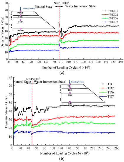
Figure 14.
Variation of dynamic stress with loading times: (a) WDS; (b) TS.
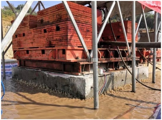
Figure 15.
Excitation test under water immersion condition.
- 2.
- Variation of dynamic stress along the depth direction
The variation of dynamic stress in the downward direction for WDS and TS is shown in Figure 16. Vibration energy absorption and the damping effect of the subgrade filler [31] results in the gradual reduction of the dynamic stresses in both subgrade beds from the subgrade surface along the downward direction. The dynamic stresses reduce quickly at the surface layer of the subgrade bed, which is consistent with the study findings obtained by Kong, X, et al. [32]. This could be attributed to the fact that the surface layer of the subgrade bed consists of coarse-grained graded gravel, which has a better dispersion effect on the dynamic stresses [33].
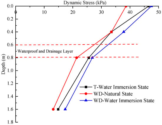
Figure 16.
Variation of dynamic stresses along the depth of subgrade.
The attenuation coefficient of the dynamic response in the downward direction could be computed by Equation (5).
where is the attenuation coefficient of the subgrade dynamic response along the depth direction, which can represent the attenuation coefficient of dynamic stress and acceleration; is the dynamic response at the subgrade surface, which can represent the dynamic stress (kPa) and acceleration (m/s2) at the surface; is the dynamic response at depth z (m) from the subgrade surface, which can represent the dynamic stress (kPa) and acceleration (m/s2) at depth z (m) from the surface.
The attenuation coefficient of the dynamic stresses along the depth for the WDS and the TS is shown in Figure 17. It could be observed from this graph that the dynamic stresses on the surface of WDS under the natural and submerged conditions and of TS under submerged conditions reduced to 34.1%, 36.5% and 32%, respectively, at a depth of 1.6 m in both of the subgrades. This shows a slight increase in the overall attenuation rate of the TS. For the WDS, the WDL is located between 0.4 m~0.8 m below the subgrade surface. In this depth range, a reduction in the attenuation coefficients by 31.57% and 23.09% in the natural state and immersed state, respectively is observed. On the contrary, the reduction of in the corresponding position of the TS is 16.99%. It could be concluded that the attenuation of dynamic stresses in the depth range where the WDL is located is significantly higher than that of the TS. This indicates that the WDL, as a flexible structural layer, has a stronger energy dissipation effect than the coarse-grained filler, and can play a major role in vibration damping and accelerate the attenuation of dynamic stresses. The attenuation coefficient under submerged conditions is considerably smaller than that under natural conditions, which indicates an increase in the dynamic stress attenuation rate after immersion of water. There is no water permeating into lower levels due to the WDL; hence, the difference between WDS and TS in the attenuation coefficient is almost insignificant. It indicates that the dynamic stress transfer process of the subgrade is influenced by the service condition, and the attenuation of dynamic stress can be promoted once the subgrade is submerged under water.
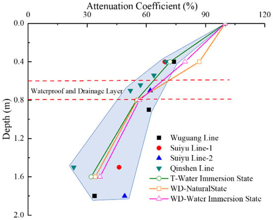
Figure 17.
Variation of dynamic stress attenuation coefficient with depth.
The dynamic stress attenuation coefficients of the WDS and the TS in the current study were compared with the dynamic stress attenuation coefficients of the Qin-Shen Line (Qinhuangdao-Shenyang high-speed railway) [34], the Wu-Guang Line (Wuhan-Guangzhou high-speed railway) [35] and the Sui-Yu Line (Suining-Chongqing high-speed railway) [36,37], as shown in Figure 17. The results show that the dynamic stress attenuation coefficient of the surface layer of the WDS is slightly more than the value of stress obtained from field testing, while for other locations, it is within the acceptable range for the measured attenuation coefficient. In general, the attenuation law of dynamic stress along the depth of the WDS is similar to that measured during the field tests. This indicates that the laying of WDL does not significantly alter the dynamic transmission characteristics of the subgrade.
- 3.
- Variation of dynamic stress along the cross-sectional direction
Figure 18 shows the distribution of dynamic stresses along the cross section at a depth of 0.4 m and 1.6 m below the subgrade surface. The dynamic stresses reach their maximum value at identical depths below the loading center, both at the WDS and TS, and gradually attenuate along the cross section as the distance from the loading center increases. It could be observed that attenuation is high near the loading center.
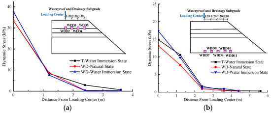
Figure 18.
Distribution of dynamic stresses along the cross-sectional direction: (a) 0.4 m below the subgrade surface; (b) 1.6 m below the subgrade surface.
The rate of attenuation of the dynamic response along the cross-sectional direction could be computed from Equation (6):
where is the rate of attenuation of the dynamic response of the subgrade in the cross-sectional direction, which represents the rate of attenuation of dynamic stress and acceleration; is the value of the dynamic response at the loading center at varying depths, which can express the dynamic stress (kPa) and acceleration (m/s2); is the dynamic response at h (m) from the loading center, which represents the dynamic stress (kPa) and acceleration (m/s2) at h(m) from the loading center.
From Figure 18, it can be seen that the variation region of dynamic stress in the cross-sectional direction is mainly concentrated in the range from 0 m to 2.4 m from the loading center, and this range is defined as the transverse main attenuation zone. The attenuation rate in this range is 88.98~99.34%. For the WDS, at various depths, the dynamic stress along the cross section at the same position from the loading center is generally higher than that in the natural state, but the attenuation rate along the transverse direction is almost the same. Under the submerged condition, the dynamic stress values at the loading centers 0.4 m and 1.6 m below the surface of the WDS (WDD2 and WDD7) are 12.9% and 16.53% larger than those at the same position in TS (TD2 and TD7), respectively. Within the transverse main attenuation zone, the attenuation rates of dynamic stresses along the transverse direction in the WDS are higher than those in the TS, indicating that the WDS can play a vital role in energy dissipation during the lateral transfer of dynamic stresses and promote its attenuation.
5.2.2. Acceleration
- Variation of acceleration with loading times
Figure 19 shows the variation of acceleration with the number of loading cycles at different depths of the subgrade. The acceleration curves for all layers of the subgrade in the early stage of the excitation test fluctuate sharply under different service conditions, similar to the pattern of dynamic stress changes. The acceleration curves are also gradually stabilized with the increase in loading times. It was observed that in the submerged state, the subgrade below the WDL reached the stable state after about 0.55 million loading times, which is significantly faster than for the position above the WDL. This could be attributed to the fact that there is no water infiltration in this position due to the laying of the WDL, because of which it takes less time to reach the stable state than the subgrade bed above the WDL which is immersed in water. For the position above the WDL, the acceleration value at stabilization is significantly higher in the immersed state than in the natural state, while the acceleration value below the WDL does not show significant variation between the two states due to the absence of water infiltration, indicating that different service conditions can cause changes in the vibration degree of the subgrade filler. The acceleration at the subgrade surface (WDD1) under the natural condition is 8.42 m/s2 after stabilization, while the acceleration at the submerged condition is 9.33 m/s2, indicating an increase of 10.81%. This could be attributed to the fact that after immersion, the subgrade surface particles are completely submerged in water. Both subgrade surface particles and water vibrate together under the vibration loading. The vibration severity is more intense under water immersion conditions than under the natural conditions, thus causing an increase in the acceleration at the subgrade surface. At the initial stage of the TS excitation test, the acceleration curves fluctuate violently. As shown in Figure 19b, the acceleration curves of the TS between 0 m~0.4 m below the subgrade surface fluctuate more significantly than those of the WDS during the entire excitation test. The acceleration curves in the range 0.8 m~1.6 m below the subgrade surface are relatively stable, and the acceleration value at the surface (TD1) after stabilization is 8.85 m/s2, which is comparatively less than that of the WDS.
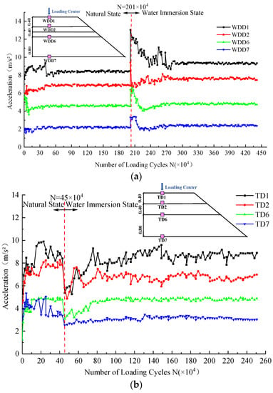
Figure 19.
Variation of acceleration with loading times: (a) WDS; (b) TS.
- 2.
- Variation of acceleration along the depth direction
Figure 20 and Figure 21 show the acceleration and attenuation coefficients along the depth for the two types of subgrades, respectively. The acceleration of both WDS and the TS are attenuated along the depth of the subgrade. The acceleration at the WDS surface reduces to 2.21 m/s2 after 1.6 m filler under the natural condition, and 2.40 m/s2 under the immersed condition. It is found to be 3.01 m/s2 under the immersed condition of the TS, with attenuation coefficients of 26.24%, 25.72% and 34.01%, respectively. From these data, it can be seen that the acceleration attenuation of WDS under both the natural conditions and the immersed conditions is higher than that of the TS. The acceleration value in the immersed state between 0.4 m~0.8 m below the surface of the WDS is reduced from 7.62 m/s2 to 4.81 m/s2, and the attenuation coefficient is reduced by 30.12%. The acceleration value in the TS is reduced from 6.99 m/s2 to 4.87 m/s2, and the attenuation coefficient is reduced by 23.95%. The reduction is smaller than that of the WDS. This indicates that the WDL can play a significant role in vibration damping and promote the attenuation of acceleration along the depth of subgrade. Whether above the WDL or below it, the variation in acceleration attenuation coefficients of WDS under different service conditions is minor. This indicates that the change in the service conditions during this test is the main reason for the change in acceleration values, and it has no evident effect on the attenuation law of acceleration. The attenuation coefficients of acceleration of the subgrade in the vertical direction during the test were compared with those of the Wu-Guang Line [35] and the Sui-Yu Line [36], as shown in Figure 21. This showed that the attenuation coefficients of acceleration along the depth during the test were within the acceptable range of field measurements, indicating that the laying of WDL did not change the transmission law of the vibration characteristics of the subgrade in the vertical direction.
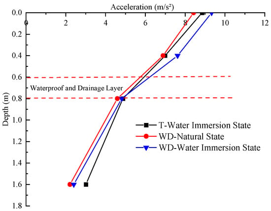
Figure 20.
Variation of acceleration along the depth of the subgrade.
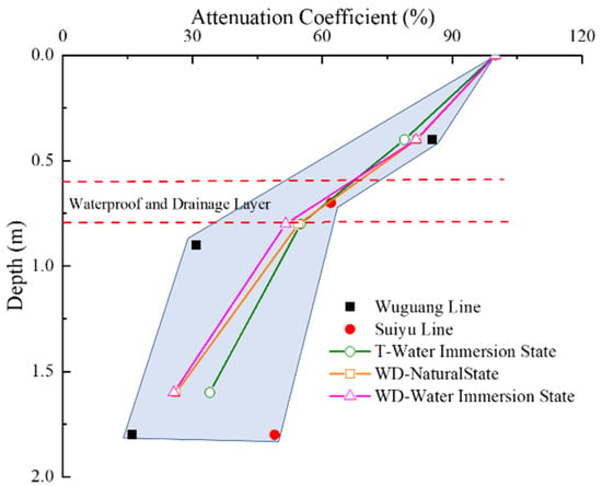
Figure 21.
Variation of acceleration attenuation coefficient with depth.
- 3.
- Variation of acceleration along the cross-sectional direction
The distribution of acceleration in WDS and TS at various depths along the cross-section is shown in Figure 22. From Figure 22, it can be seen that the closer the location is to the loading center, the higher the acceleration at different depths for both types of subgrades. The acceleration decreases gradually with the increase in the distance from the loading center, which is similar to the distribution of dynamic stresses in the cross-sectional direction. At a depth of 0.4 m below the surface of both subgrade types, there is also a transverse main attenuation zone of acceleration in the range from 0 m to 2.4 m from the loading center, with the attenuation rate of 65.67~89.63%. In general, the attenuation rate along the transverse direction of the subgrade under immersion conditions is higher than that under natural conditions. Comparing the WDS with the TS, both in the submerged state, it is found that the acceleration in TS is higher than that for WDS except for the corresponding position of WDD2. However, its acceleration attenuation rate along the transverse section is comparatively less than that of the WDS. This indicates that the WDL can also play a major role in promoting the acceleration attenuation in the transverse direction. It could be noted that at 1.6 m below the surface, the variation of acceleration is more uniform than the variation of dynamic stresses along the transverse direction of the subgrade, which may be related to the location near raft with greater stiffness.
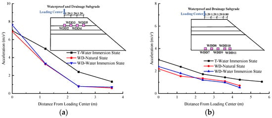
Figure 22.
Acceleration variation along the cross-sectional direction: (a) 0.4 m below the subgrade surface; (b) 1.6 m below the subgrade surface.
6. Conclusions
The Hang-Tai High-speed Railway is the first railway in China to pass through the diatomaceous earth area. Diatomaceous earth foundation has stability problems when exposed to moisture. To solve it, the WDS based on CWDP is proposed. In addition, immersion and excitation tests were carried out to examine the waterproof performance and dynamic characteristics thereof. The following conclusions were obtained:
- The lap joint is a key element in the waterproof performance of the WDL. From the lap joint waterproof performance test, the effectiveness of the 15 cm lap joint width is verified. The experiment shows that if lap joint between adjacent CWDPs is ensured, it can exhibit a positive waterproof effect. The width could meet the waterproof performance requirements of the WDL;
- Compared to the TS, there was no obvious change in the moisture content of the soil below the WDL after the immersion test of the WDS, indicating that the WDS can provide a good waterproof and drainage effect and can effectively be used for railway construction in diatomaceous earth areas;
- The WDL is a flexible structure, with a more significant energy dissipation effect which can promote the attenuation of dynamic response in the depth direction. The result of the excitation test shows that within the depth range of the WDL, the reduction of dynamic stress attenuation coefficient and acceleration attenuation coefficient of the WDS are 23.09% and 30.12%, respectively, which are 6.11% and 6.16% higher than that of the TS. In addition, compared with the measured data of the existing high-speed railway subgrade, the WDL did not change the transfer behavior of dynamic characteristics;
- The service condition can affect dynamic response of the WDS. The dynamic stresses and accelerations in the natural state are comparatively less than those in the immersed state. In addition, the dynamic stress is significantly more influenced by the service condition than the acceleration;
- During the construction, there will be a series of behaviors that cause disturbance to soil structure, such as excavation and filling. In addition, the diatomaceous earth has the characteristics of softening, swelling and disintegration when exposed to water. With due consideration of these challenges, during the construction of line engineering in diatomaceous earth area, the diatomaceous earth foundation should be reinforced in addition to the adoption of well-designed waterproof and drainage measures to ensure the long-term stability of the structures.
The present study could provide a reference for the design and construction of drainage protection for later projects in diatomaceous earth areas or other special soil such as soft soil. However, due to time constraints, the work in this paper is limited and further studies can be carried out on the diatomaceous soil subgrade as follows:
- Only one type of waterproof and drainage structure has been studied in this paper. In the future, other types of waterproof and drainage structures can continue to be studied in in diatomaceous earth area;
- The load in the dynamic characteristics tests in the study is a simulated train load, which differs from the real moving train load. Therefore, dynamic tests under a moving train load can be carried out on this subgrade section after the line is in operation to analyze the dynamic response of the new subgrade.
Author Contributions
Conceptualization, Q.S. and Q.Z.; methodology, H.G., Q.S. and Q.Z.; software, H.G.; validation, H.G.; formal analysis, H.G. and Q.Z.; investigation, H.G.; resources, Q.S. and Q.Z.; data curation, Q.S.; writing—original draft preparation, H.G.; writing—review and editing, Q.Z. and M.M.N.; visualization, H.G.; supervision, Q.Z., H.Y. and F.C.; project administration, T.L.; funding acquisition, T.L. and H.Y. All authors have read and agreed to the published version of the manuscript.
Funding
This research was funded by China State Railway Group Co., Ltd. (No. J2021G002) and China Academy of Railway Sciences Corporation Limited (No. 2021YJ071).
Institutional Review Board Statement
Not applicable.
Informed Consent Statement
Not applicable.
Data Availability Statement
Not applicable.
Conflicts of Interest
The authors declare no conflict of interest.
References
- Lu, C. Innovation and Practice for Engineering Quality Management of High Speed Railway in China. China Railw. Sci. 2015, 36, 1–10. [Google Scholar]
- Zhai, W.; Liu, P.; Lin, J.; Wang, K. Experimental investigation on vibration behaviour of a CRH train at speed of 350 km/h. Int. J. Rail. Transp. 2015, 3, 1–16. [Google Scholar] [CrossRef]
- Zhu, G. Overall Comments on Study and Application of Ballastless Track at Home and Abroad. J. Railw. Eng. Soc. 2008, 118, 28–30. [Google Scholar]
- TB 10621-2014; Code for Design of High Speed Railway. China Railway Press: Beijing, China, 2014.
- Ovalle, C.; Arenaldi-Perisic, G. Mechanical behaviour of undisturbed diatomaceous soil. Mar. Georesources Geotechnol. 2021, 39, 623–630. [Google Scholar] [CrossRef]
- Zhang, Y.; Guo, C.; Yao, X.; Qu, Y.; Zhou, N. Engineering geological characterization of clayey diatomaceous earth deposits encountered in highway projects in the Tengchong region, Yunnan, China. Eng. Geol. 2013, 167, 95–104. [Google Scholar] [CrossRef]
- Diaz-Rodriguez, J.A. Diatomaceous soils: Monotonic behavior. In Proceedings of the 5th International Symposium on Deformation Characteristics of Geomaterials (IS), Seoul, Republic of Korea, 1–3 September 2011; pp. 865–871. [Google Scholar]
- Arenaldi Perisic, G.; Ovalle, C.; Barrios, A. Compressibility and creep of a diatomaceous soil. Eng. Geol. 2019, 258, 105145. [Google Scholar] [CrossRef]
- Zhang, Y.; Guo, C.; Qu, Y.; Yao, X. Research on mechanical properties of swelling diatomite and their geohazard effects. Rock Soil Mech. 2013, 34, 23–30. [Google Scholar] [CrossRef]
- Guo, C.; Zhou, N.; Fu, X.; Zhang, Y.; Zhang, R. The optimization design of the research on the formation mechanism, prevention and control of landslide along clayey diatomite highway in Tengchong, Yunnan Pzovince. Geol. Bull. China 2013, 2021–2030. [Google Scholar]
- Huang, J.J.; Su, Q.; Cheng, Y.M.; Liu, B.; Liu, T. Improved performance of the subgrade bed under the slab track of high-speed railway using polyurethane adhesive. Constr. Build. Mater. 2019, 208, 710–722. [Google Scholar] [CrossRef]
- Fu, Q.; Chen, X.; Cai, D.; Yang, J.; Yang, G. Full-Section Asphalt Concrete Waterproof Sealing Structure for High Speed Railway Subgrade. China Railw. Sci. 2020, 41, 24–33. [Google Scholar] [CrossRef]
- Liu, S.; Yang, J.; Chen, X.; Yang, G.; Cai, D. Application of Mastic Asphalt Waterproofing Layer in High-Speed Railway Track in Cold Regions. Appl. Sci. 2018, 8, 667. [Google Scholar] [CrossRef]
- Wu, K.; Liu, Z.; Li, W.; Zhu, C.; Xi, B.; Gong, Q.; Lin, Q.; Chen, G.; Fu, Y. Fully Enclosed Waterproof and Drainage Composite Structure and the Subgrade Structure with This Composite Structure. CN203834304U, 17 September 2014. [Google Scholar]
- Duan, J.; Yang, X.; Yang, G.; Xu, Y. Field test on dynamic characteristics of composite waterproof plate subgrade bed in expansive soil areas. J. China Railw. Soc. 2016, 38, 120–125. [Google Scholar]
- Yang, G.; Wang, L. Model test on vibration characteristic of fully-closed express railway cutting subgrade in swelling soil area. J. Cent. South Univ. (Sci. Technol.) 2014, 45, 2824–2829. [Google Scholar]
- Xiao, C.; Zhihui, Z.; Hua, Z. Experiment on Anti-clogging Capability of Capillary Drain Belt. J. China Inst. Water Resour. Hydropower Res. 2010, 8, 294–298. [Google Scholar]
- Cheng, D.; Yuqiao, C.; Yipeng, G.; Chunyan, Z. Experimental study on drainage characteristic of capillary drainage belt. J. Railw. Sci. Eng. 2017, 14, 2096–2103. [Google Scholar] [CrossRef]
- Zeng, L.; Wang, Z.; Wang, P.; Liu, D.; Xie, M. Research on Utilizing New-type Drainage Material to Optimize the Seepage-capacity of Landfill. Environ. Eng. 2017, 35, 18–22. [Google Scholar]
- Zhang, Z.; Zhang, J.; Huang, J.; Zhang, T.; Tang, D.; He, K.; Li, R. Efficacy of a Drainage System in Remediating Saline-alkali Soils in the Alpine Region of Qinghai Province. J. Irrig. Drain. 2018, 37, 78–85. [Google Scholar] [CrossRef]
- Zhang, D.; Wang, N.; Chen, F.; Zhang, J. Study on Drainage Performance Test and Subgrade Drainage Application of Capillary Drainage Pipe. Railw. Eng. 2023, 63, 127–131. [Google Scholar] [CrossRef]
- Sulei, Z.; Tong, B.; Chungsik, Y.; Chang, L.; Pengfei, L.; Liping, C. Design, Test, and Engineering Application of a Composite Waterproof and Drainage System in Tunnels. China J. Highw. Transp. 2021, 34, 198–208. [Google Scholar]
- Yuan, M. The Structure, Composition and Their Engineering Implication of Diatomite in Zhejiang. J. Railw. Eng. Soc. 2019, 36, 17–22. [Google Scholar]
- Yaoyue, F.; Jun, J.; Huanghui, J. Research on the Microstructure and the Mechanical Properties of Shengzhou Diatomite. Low Temp. Archit. Technol. 2019, 41, 75–77. [Google Scholar]
- Yuan, M.; Hongtao, L.; Jianfeng, Z.; Xiang, C.; Yuesheng, W. Experimental study on composition and microstructure characteristics of diatomite. Geotech. Investig. Surv. 2021, 49, 5–8. [Google Scholar]
- Liu, H. Comparative study on the bearing capacity of diatomite from Shengzhou between pressuremeter test and plate loading test. Geotech. Investig. Surv. 2021, 49, 14–18. [Google Scholar]
- Cai, X.; Liu, W.; Wang, P.; Ning, X. Effect of land subsidence on regularity of double-block ballastless track. Eng. Mech. 2014, 31, 160–165. [Google Scholar] [CrossRef]
- Bian, X.; Duan, X.; Li, W.; Jiang, J. Track settlement restoration of ballastless high-speed railway using polyurethane grouting: Full-scale model testing. Transp. Geotech. 2021, 26, 100381. [Google Scholar] [CrossRef]
- Jiang, H.; Li, Y.; Wang, Y.; Yao, K.; Yao, Z.; Xue, Z.; Geng, X. Dynamic performance evaluation of ballastless track in high-speed railways under subgrade differential settlement. Transp. Geotech. 2022, 33, 100721. [Google Scholar] [CrossRef]
- Wang, L.; Yang, G. Model test on effects of subgrade dynamic characteristics by using semi-rigid water-proof structure layer. J. Cent. South Univ. Sci. Technol. 2013, 44, 4244–4250. [Google Scholar]
- Zhang, C.L.; Jiang, G.L. Full-scale model testing of the dynamic response of lime-stabilized weathered red mudstone subgrade under railway excitation. Soil Dyn. Earthq. Eng. 2020, 130, 105999. [Google Scholar] [CrossRef]
- Kong, X.; Jiang, G.; Dong, X.; Li, A. Dynamic characteristics of subgrade bed for ballastless track. In Proceedings of the International Conference on Geotechnical & Earthquake Engineering, Chengdu, China, 25–27 October 2013; pp. 105–111. [Google Scholar] [CrossRef]
- Cai, Y.; Xu, L.; Liu, W.; Shang, Y.; Su, N.; Feng, D. Field Test Study on the dynamic response of the cement-improved expansive soil subgrade of a heavy-haul railway. Soil Dyn. Earthq. Eng. 2020, 128, 105878. [Google Scholar] [CrossRef]
- Gang, L.; Qiang, L.; Liang, Z.; Liangwei, J. Analysis of the design load on the high-speed railway ballsted track subgrade. J. Railw. Sci. Eng. 2015, 12, 475–481. [Google Scholar] [CrossRef]
- Guo, Z.; Wei, L.; He, Q.; Qu, C. Tests for dynamic response of ballastless track subgrade of wu-guang high-speed railway. J. Vib. Shock. 2013, 32, 148–152. [Google Scholar] [CrossRef]
- Xiao, H.; Jiang, G.; Wei, Y. Dynamic test analysis on ballastless-track column-net structure subgrade of the Suining-Chongqing Railway Line. J. China Railw. Soc. 2010, 32, 79–84. [Google Scholar]
- Liu, G.; Luo, Q.; Zhang, L.; Chen, H.; Chen, J. Analysis on the dynamic stress characteristics of the unballsted track subgrade under train loading. J. China Railw. Soc. 2013, 35, 86–93. [Google Scholar]
Disclaimer/Publisher’s Note: The statements, opinions and data contained in all publications are solely those of the individual author(s) and contributor(s) and not of MDPI and/or the editor(s). MDPI and/or the editor(s) disclaim responsibility for any injury to people or property resulting from any ideas, methods, instructions or products referred to in the content. |
© 2023 by the authors. Licensee MDPI, Basel, Switzerland. This article is an open access article distributed under the terms and conditions of the Creative Commons Attribution (CC BY) license (https://creativecommons.org/licenses/by/4.0/).