Article

Optimal Parameter Identification of Single-Sensor Fractional Maximum Power Point Tracker for Thermoelectric Generator

by
Abdul Ghani Olabi
1,2,*,
Hegazy Rezk
3,4,
Enas Taha Sayed
5,
Tabbi Awotwe
2,
Samah Ibrahim Alshathri
6,* and
Mohammad Ali Abdelkareem
1,4
1
Sustainable Energy & Power Systems Research Centre, RISE, University of Sharjah, Sharjah P.O. Box 27272, United Arab Emirates
2
Mechanical Engineering and Design, School of Engineering and Applied Science, Aston University, Aston Triangle, Birmingham B4 7ET, UK
3
Department of Electrical Engineering, College of Engineering in Wadi Alddawasir, Prince Sattam bin Abdulaziz University, Wadi Alddawasir 11991, Saudi Arabia
4
Electrical Engineering Department, Faculty of Engineering, Minia University, Minia 61111, Egypt
5
Chemical Engineering Department, Faculty of Engineering, Minia University, Minia 61111, Egypt
6
Department of Information Technology, College of Computer and Information Sciences, Princess Nourah bint Abdulrahman University, P.O. Box 84428, Riyadh 11671, Saudi Arabia
*
Authors to whom correspondence should be addressed.
Sustainability 2023, 15(6), 5054; https://doi.org/10.3390/su15065054
Submission received: 17 December 2022 / Revised: 18 January 2023 / Accepted: 22 January 2023 / Published: 13 March 2023
(This article belongs to the Special Issue Advances in Zero Energy Buildings)

Abstract

:
A thermoelectric generator (TEG) is used for converting temperature difference and into DC directly to electric energy based on the Seebeck effect. This new technology has attracted researchers of sustainable energy. The energy obtained from the TEG depends on the temperature difference between the two sides of the TEG. A reliable MPP “maximum power point” tracker (MPPT) is mandatory to guarantee that the TEG is working close to the MPP under different operational conditions. There are two common methods that have been widely used to track the MPP: hill climbing (HC) and incremental conductance (INR). The HC method is very fast in tracking the MPP; however, oscillation can occur under a high steady state. On the contrary, the INR method needs more time to track the MPP but does not oscillate around the MPP. To overcome these issues, fractional control is adopted. Furthermore, the proposed MPPT requires only a single current sensor, as opposed to conventional MPPTs, which require at least two sensors: current and voltage sensors. The cost of the control system is reduced when the number of sensors is reduced. Hunger games search optimization is used to estimate the parameters of a single sensor optimized fractional MPPT (OFMPPT). During the optimization process, three parameters were assigned as decision variables: proportional gain, integral gain, and order, with the objective function being the TEG’s energy. The results demonstrated the superiority of OFMPPT in both transient and steady state compared to HC and INR.

1. Introduction

The rapid advancement of fossil fuel utilization has resulted in significant environmental consequences, which are evident in abnormal climate change [1,2]. Various methods for controlling climate change have been developed, including: (1) increasing the efficiency of current processes through heat recovery [3,4], especially in energy intensive consuming industries [5,6]; (2) using efficient and environmentally friendly energy conversion devices such as fuel cells [7,8]; (3) and/or relying on sustainable renewable energy sources with low or no environmental impacts [9,10]. In the current stage, waste heat recovery is the most credible solution until commercial renewable energy sources are developed at reasonable prices compared to those of conventional fuels. Significant advances in waste heat recovery have recently been made [11,12]. Thermoelectric generators are used to convert temperature differences and direct current to electric energy using the Seebeck effect. The improved materials and geometry of the thermoelectric generator of the thermoelectric generator (TEG) have increased its efficiency [13]. Many thermoelectric materials are being explored for power generation applications, such as GeTe [14], PbTe [15], Bi2Te3−xSex [16], Bi2Te3 [17], and silicides [18]. Despite this, TEG efficiency is low. Additional developments and efforts are still necessary to improve the TEG’s performance. One possible solution for increasing TEG efficiency is the development of novel materials. The obtained TEG energy is primarily determined by the temperature difference between the two sides of the TEG. A second approach is to increase its harvested energy by employing maximum power point (MPP) trackers (MPPTs) [19]. MPPTs are now essential components in the construction of a low-cost TEG power source. MPPT control is typically accomplished through the use of DC–DC converters [20]. Based on the maximum power theorem, the MPPT forces the TEG to work near the MPP by adjusting the load to be balanced by the TEG’s internal resistance [20].
Various MPPTs for TEG systems have been discovered in the literature, ranging from traditional techniques to modern intelligent techniques [21,22]. The hill climbing (HC) method has previously been the most frequently used for photovoltaic or TEG systems [21]. Although the HC MPPT can rapidly reach the MPP, it oscillates around the MPP at steady state conditions. On the other hand, the incremental resistance (INR), under steady state conditions, has a slow dynamic performance but no oscillations around the MPP. The fundamental idea behind the INR MPPT is that the power–current derivative is zero at MPP. Because the error signal is very small around the MPP, the INR step size is chosen according to the error signal to reduce steady state oscillations. An integrator is used to model the INR in this case, and the error signal is fed into the integrator input [23].
Recently, fractional control has been used in a variety of scientific and engineering fields. The fractional order is commonly used to improve controller performance in both linear and nonlinear systems (closed-loop). The “fractional order control” (FOC) method is based on the fractional calculus principle. Because of its advantages, the FOC is desired compared with the integer order control method [24]. Compared to integer-order control, fractional control is flexible in design and has demonstrated superior results [25]. As a result, fractional control has been used to improve the performance of conventional INR by replacing the discrete integrator with a discrete fractional PI controller. To increase the performance of optimized fraction MPPT, three main parameters must be defined correctly: integration gain (KI), proportional gain (KP), and fraction order (λ).
Reducing the number of required sensors for tracking the MPP, on the other hand, reduces the cost of the controller. Most MPPTs require at least two [26,27] or three [28] sensors for TEG applications: a current sensor, a voltage sensor, and a temperature sensor. Park et al. [28] proposed a TEG MPPT that employs three sensors: two temperature sensors and one voltage sensor. This will raise the cost of the control system. As a result, the goal of this paper is to address all of the issues mentioned above in one configuration: improving transit response, eliminating oscillation around the MPP, and reducing the number of sensors. To accomplish this, the hunger games search (HGS) optimization algorithm was used to determine the best parameters for single-sensor optimized fractional MPPT (OFMPPT). The KI, KP, and λ are used as decision variables during the parameter identification process, whereas the harvested energy from the TEG is the objective function that must be maximized.
The main contributions of the paper can be outlined as follows.
For first time, a single-sensor MPPT has been applied with a TEG power source;
Optimal parameters of OFMPPT have been defined using hunger games search optimization;
Reduction in the number of sensors;
Steady state and dynamic tracking responses are improved simultaneously.
The second section describes the TEG power system. MPPTs with a single sensor have been examined in Section 3. Section 4 defines the procedure for identifying OFMPPT parameters using hunger games search optimization. Section 5 contains a discussion and presentation of the results. Section 6 provides a summary of the primary findings.

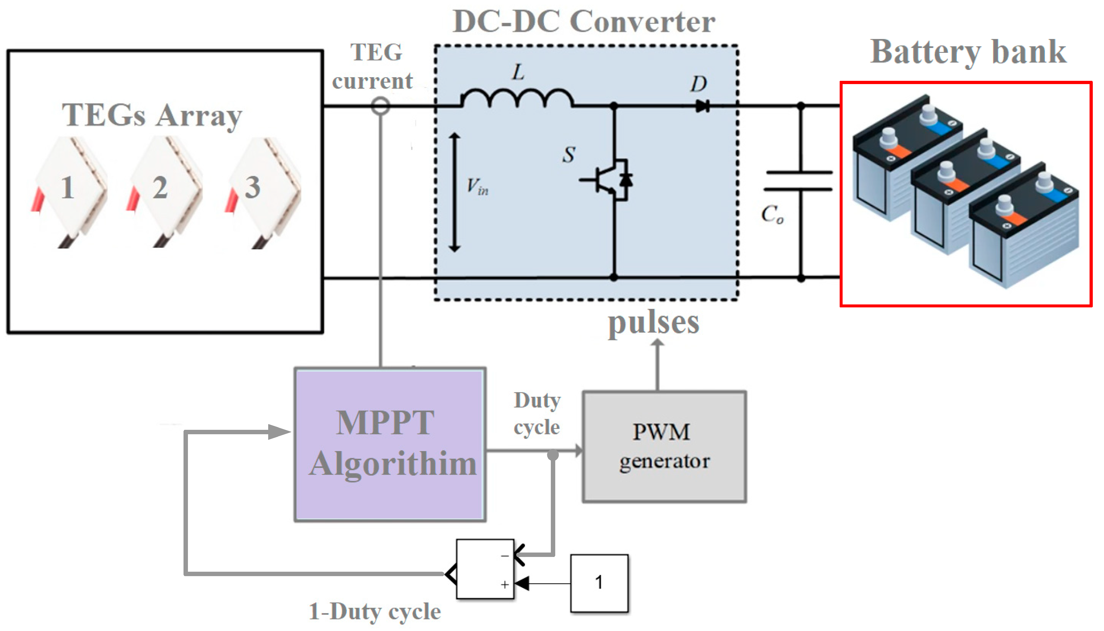
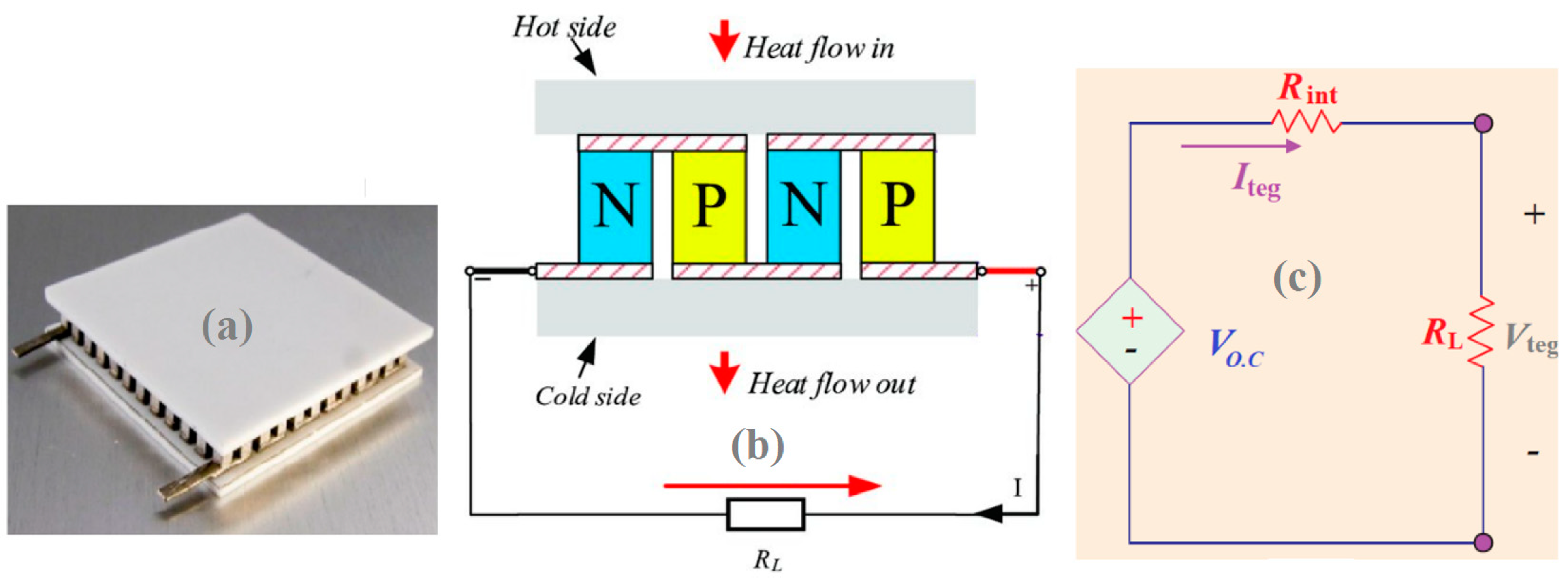
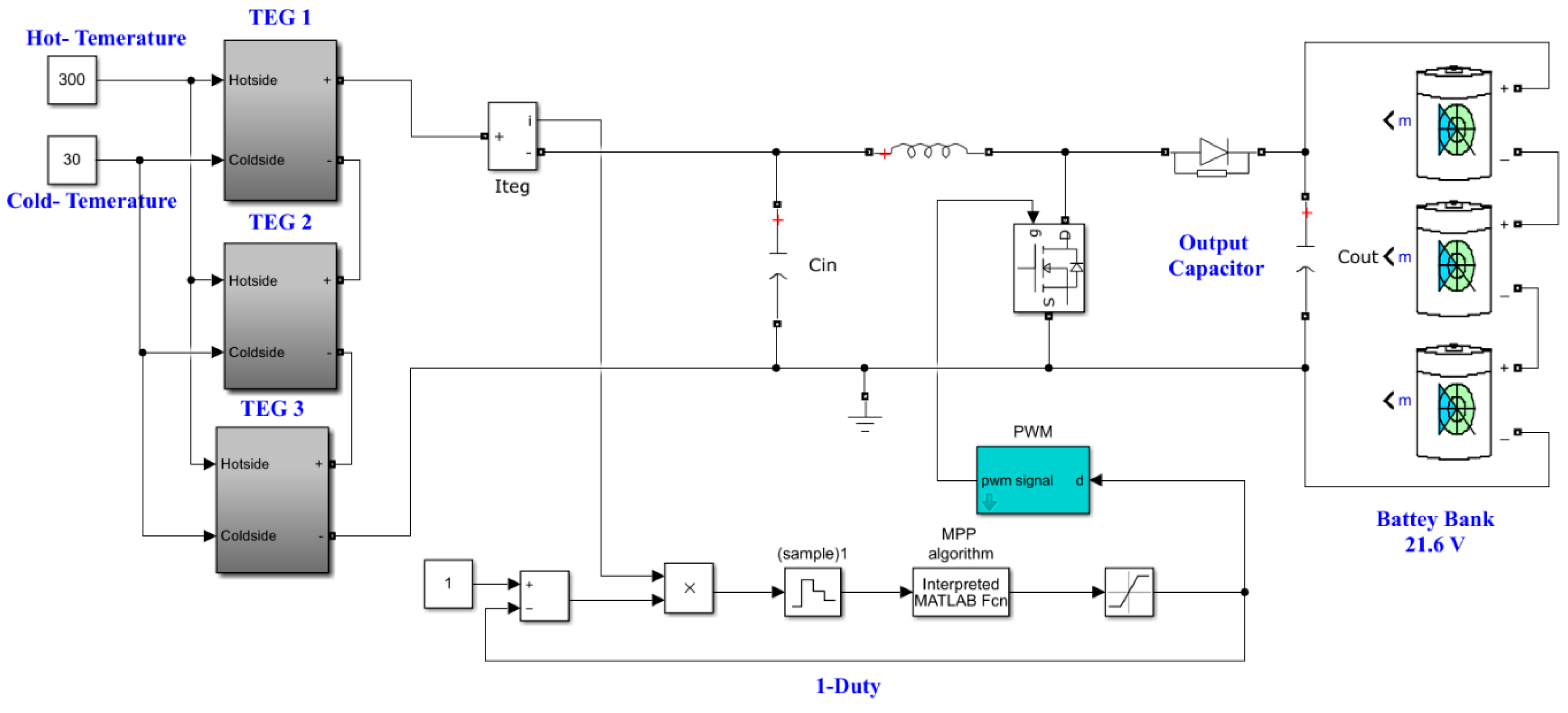
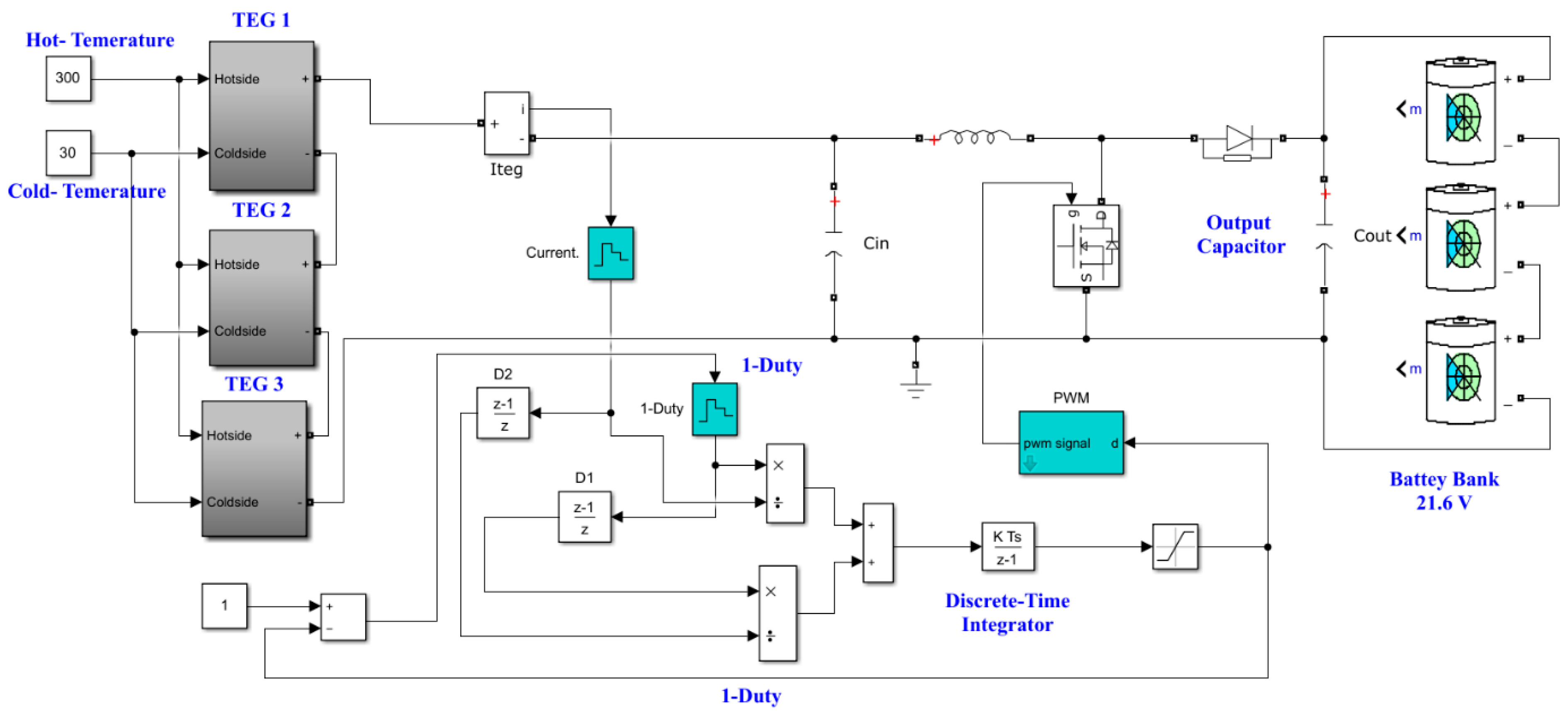
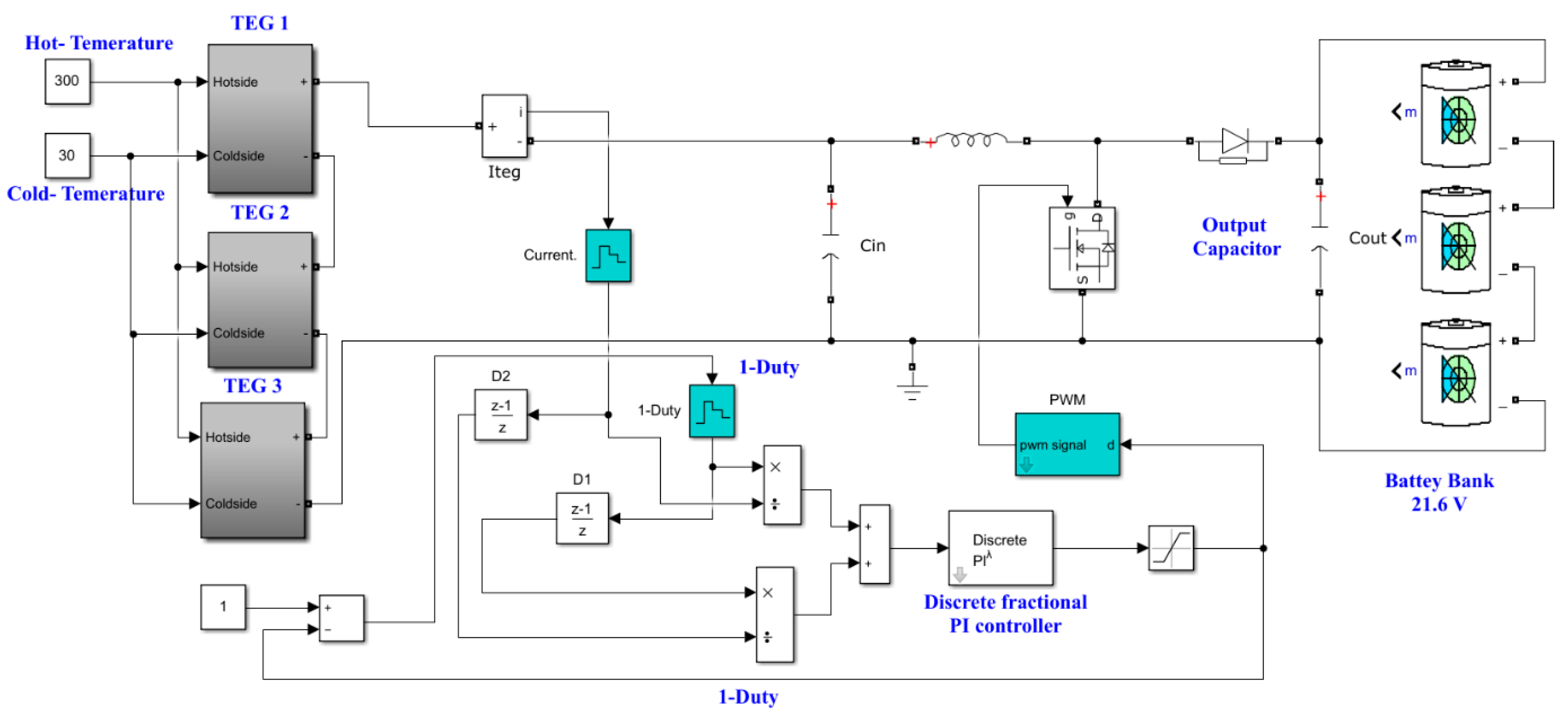
2. TEG’s Power Conversion System

The power conversion process for the TEG system is shown in Figure 1. It has a battery bank, a boost DC–DC converter, an MPPT controller, and a TEGs array. The boost DC–DC converter takes the low output voltage of the TEG array and raises it to an appropriate DC voltage level that can be used by the battery bank or the DC link. In addition to this, it is responsible for maximizing the energy that can be harvested from the TEG by using an MPPT algorithm to update the duty cycle (D) so that it corresponds to the MPP [21]. As shown in the following equation, the output voltage of the boost converter, which represents the voltage of the battery (Vb), is correlated to the input voltage, which represents the voltage of the TEG (Vteg).
V b = 1 1 D × V t e g
The TEG is a semiconductor device that generates a DC voltage via the Seebeck effect. Figure 2a depicts the common TEG view. As seen in Figure 2b, the TEG’s basic unit is a thermocouple made up of n-type and p-type semiconductors. The p-type and n-type units are coupled in series to increase the output voltage. To reduce thermal resistance, the p-type and n-type units are thermally coupled in parallel [28] and the units are sandwiched between two ceramic sheets to form hot and cold sides. To form cold and hot sides, the units are sandwiched among two ceramic sheets.
When a temperature variance appears between the two sides of the TEG, the Seebeck effect generates a DC voltage. Figure 2c depicts a simple equivalent-circuit of the TEG. The open-circuit voltage is primarily determined by the difference in temperature between the cold and hot parts, and this can be calculated as follows:
V O · C = α s b ( T h o t T c o l d ) = α s b · Δ T
where αsb is the Seebeck coefficient
  • Thot is the cold side temperature
  • Tcold is the hot side temperature
Heat flow from the high-temperature side (Qh) to the low-temperature side (Qc) can be estimated using the heat–energy equilibrium theory [27] in the following way:
Q h = α s b I t e g T h o t + K Δ T 0.5 I t e g 2 R int
Q c = α s b I t e g T c o l d + K Δ T + 0.5 I t e g 2 R int
where the thermal conductivity coefficient is K. To a large extent, the TEG output power, Pteg, is determined by the temperature difference between the two sides of the TEG. The following equation can be used to determine this value:
P t e g = Q h Q c = ( α s b · Δ T I t e g R int ) I t e g = V t e g I t e g
based on Figure 2, and using KVL, a formula for the voltage produced by the TEG, Vteg, could be written as follows:
V t e g = α s b · Δ T I t e g R int = V O · C I t e g R int = I t e g R L
To summarize, Pteg is expressed as follows:
P t e g = ( α s b · Δ T ) 2 R L ( R L + R int ) 2

3. Single-Sensor MPPTs

As previously stated, most MPPTs used to track the MPP of the TEG require at least two or three sensors: a current sensor, a voltage sensor, and possibly a temperature sensor. According to Equation (1), the TEG voltage is proportional to (1 − D) under constant battery voltage or DC-link voltage in DC grids. As a result, rather than using a voltage sensor, the value (1 − D) can be used to substitute the TEG voltage. As a result, this concept has been implemented in this work. Three MPPT strategies, including incremental resistance, hill climbing, and optimized fractional MPPT, are examined.

3.1. Hill Climbing MPPT

The main HC-MPPT’s benefit is that it is easy to implement. HC-MPPT has been used in a wide variety of contexts and is therefore very common. During the tracking process, HC adjusts the boost converter’s duty cycle [21]. The Matlab model of HC-MPPT combined with the TEG and boost converter is shown in Figure 3. TEG current is measured and multiplied with (1 − D) to obtain the objective function required to be maximum. Based on the change in the objective function, the duty cycle will be revised, raising the duty cycle with positive change in the objective function. On the other hand, by reducing the duty cycle with a negative change in the objective function, the main drawback of HC-MPPT is that it exhibits significant oscillations around the MPP in steady state conditions.

3.2. Incremental Resistance MPPT

The INR-MPPT is based on the fact that the derivative of the power over current (dP/dI) is zero at MPP. Further details regarding INR-MPPT can be found in [23]. Considering that the TEG voltage is proportional with (1 − D), the error signal e(t) could be estimated by the following relations.
d p d I @ M P P = d ( V × I ) d I = d ( [ 1 D ] × I ) d I = [ 1 D ] + I d [ 1 D ] d I = 0 ,
d [ 1 D ] d I + [ 1 D ] I = [ 1 D ] t [ 1 D ] ( t 1 ) I t I ( t 1 ) + [ 1 D ] ( t ) I ( t ) = 0 .
Moreover,
e t = [ 1 D ] t [ 1 D ] ( t 1 ) I t I ( t 1 ) + [ 1 D ] ( t ) I ( t ) .
Because e(t), or “the error signal”, is small in the vicinity of the MPP, the steady state oscillations can be reduced by adjusting the step size of the INR-MPPT. A discrete time integrator (DTI), as described in Figure 4, is used to accomplish this modeling of the INR-MPPT. The error signal is used as DTI’s input.

3.3. Optimized Fractional MPPT

Fractional order control (FOC) was used to overcome the slow dynamic of conventional INR-MPPT. As shown in Figure 5, the DTI is replaced by a discrete fraction PI controller to form the OFMPPT. The FOC “a non-integer order” offers high robustness and design flexibility.
The fractional PI transfer function can be expressed using the following equation [29]:
T c s = k p + k I s λ
where
  • Tc controller transfer function
  • k I  is integral gain
  • λ  denotes the fractional order
  • k p  is proportional gain

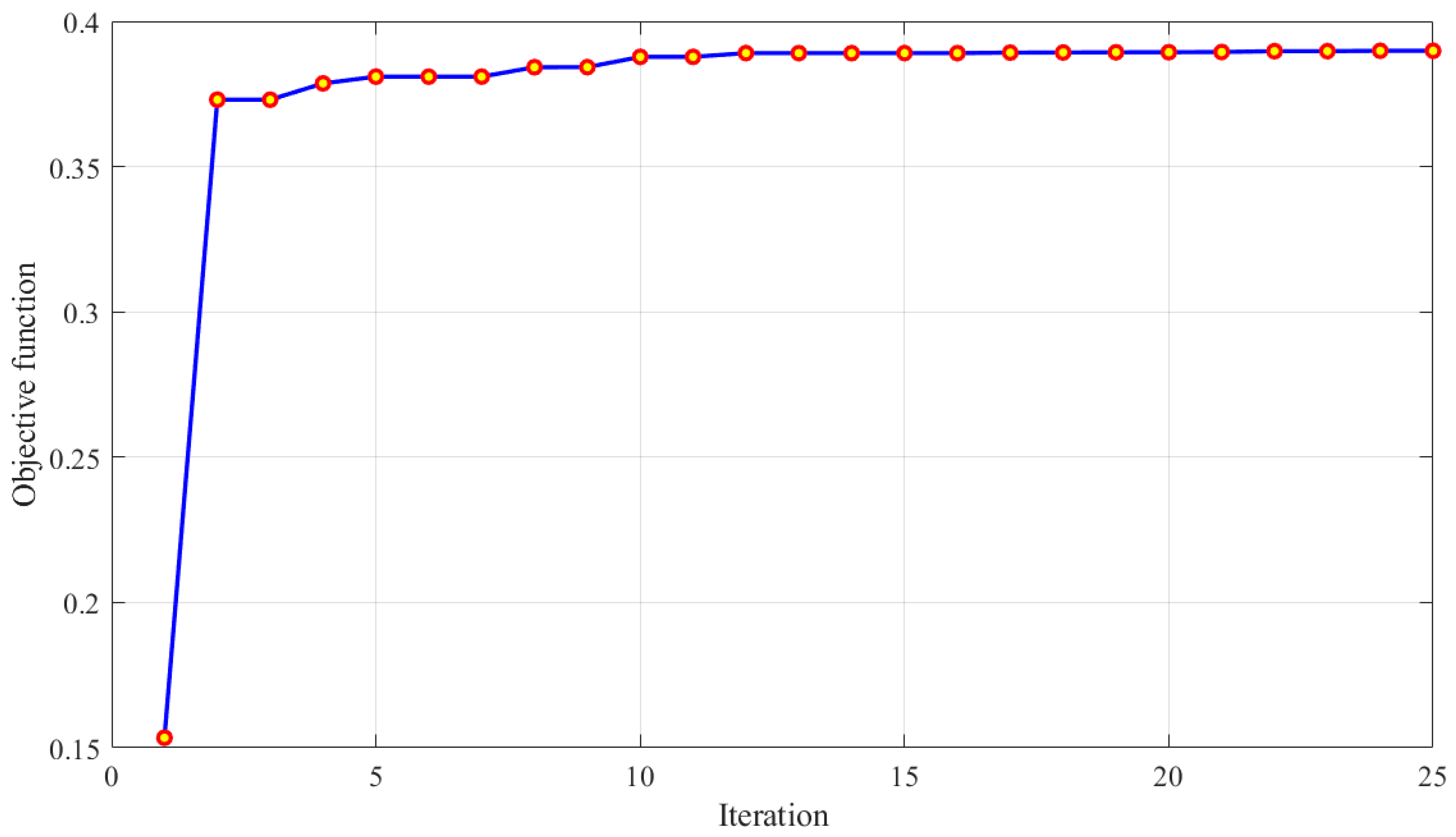
4. Parameters Identification Process of OFMPPT

4.1. Objective Function

The proportional and integration gains as well as the fraction order of single-sensor OFMPPT must all be correctly determined. The hunger games search optimization algorithm was used to accomplish this issue. The proportional and integration gains together with fraction order are utilized as decision variables through the optimization process, whereas the energy generated from the TEG is the objective function that needs to be maximized. The objective function problem argument is as follows:
f = arg x R m a x 0 t I t e g 1 D d t
where t is the simulation time and x is the set of input variables.

4.2. Hunger Games Search

To express the contraction mode’s approaching behavior mathematically, the following relations are suggested [30]:
X t + 1 = X t · 1 + r a n d n 1 , r 1 < l W 1 · X b + R · W 2 · X b X t , r 1 > l , r 2 > E W 1 · X b R · W 2 · X b X t , r 1 > l , r 2 < E
where  R  denotes a random value [−a, a].
  • r 1  and  r 2  are randoms in range between [0, 1].
  • randn(1) denotes a random number.
  • t denotes the current iteration.
  • W 1  and  W 2  are the hunger weights.
  • X t  is the portion of every particle.
The expression of E is presented as in Equation (14).
E = sech F i B F
where  i 1,2 , , n F ( i )  displays each individual’s fitness value;  B F  represents the best fitness
S e c h  denotes the hyperbolic function  sech x = 2 e x + e x .
The expression of  R  is defined in Equation (15)
R = 2 × a × r a n d a
a = 2 × ( 1 t M a x _ i t e r )
where  r a n d  denotes a random value
  • M a x _ i t e r  is the maximum number of iterations.
The expression of  W 1  and  W 2  are presented in Equations (17) and (18), respectively.
W 1 ( i ) = h u n g r y i · N S H u n g r y × r 4 , r 3 < l 1 r 3 > l
The formula of  W 2  in Equation (18) is shown as follows:
W 2 ( i ) = 1 e x p h u n g r y i S H u n g r y × r 5 × 2
where  h u n g r y  denotes the hunger of every particle
  • N  denotes the number of particles
  • S H u n g r y  is the sum of hungry feelings of all particles.
  • r 3 , r 4 , and  r 5  denote random values.
The expression of  h u n g r y i  is presented below:
h u n g r y i = 0 , A l l F i t n e s s ( i ) = = B F h u n g r y i + H , A l l F i t n e s s i ! = B F
where  A l l F i t n e s s i  is the fitness of each individual in the present iteration.
The expression for  H  is defined as in Equation (20).
T H = F i B F W F B F × r 6 × 2 × ( U B L B )
H = L H × 1 + r , T H < L H T H , T H L H
where  r 6  is a random number between  0 , 1 F ( i )  denotes the fitness value of every individual.  B F  denotes the best fitness.
The worst fitness is denoted by WF, and the maximum and minimum limits are denoted by UB and LB, respectively. The hunger sensation H has a lower bound, LH.

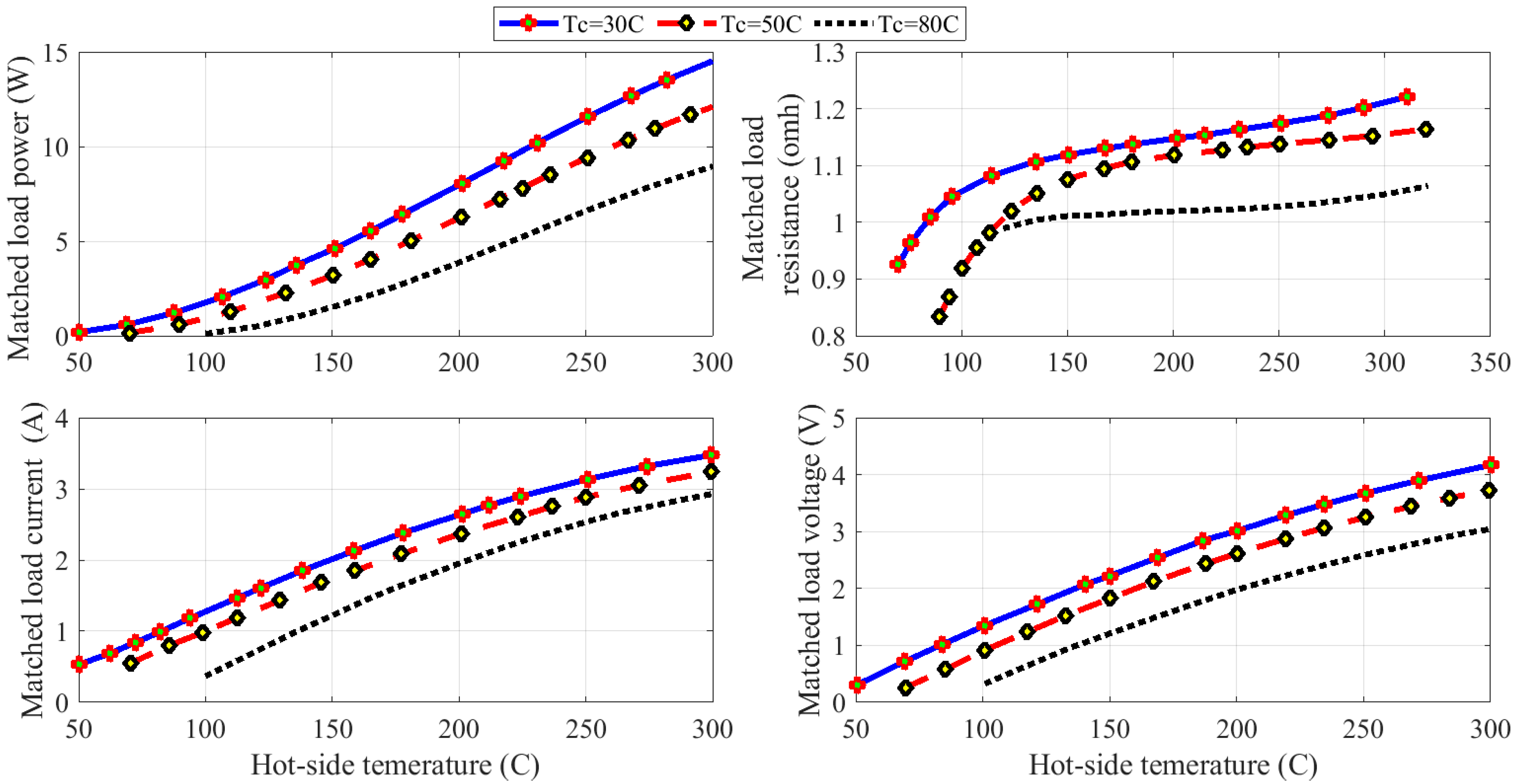
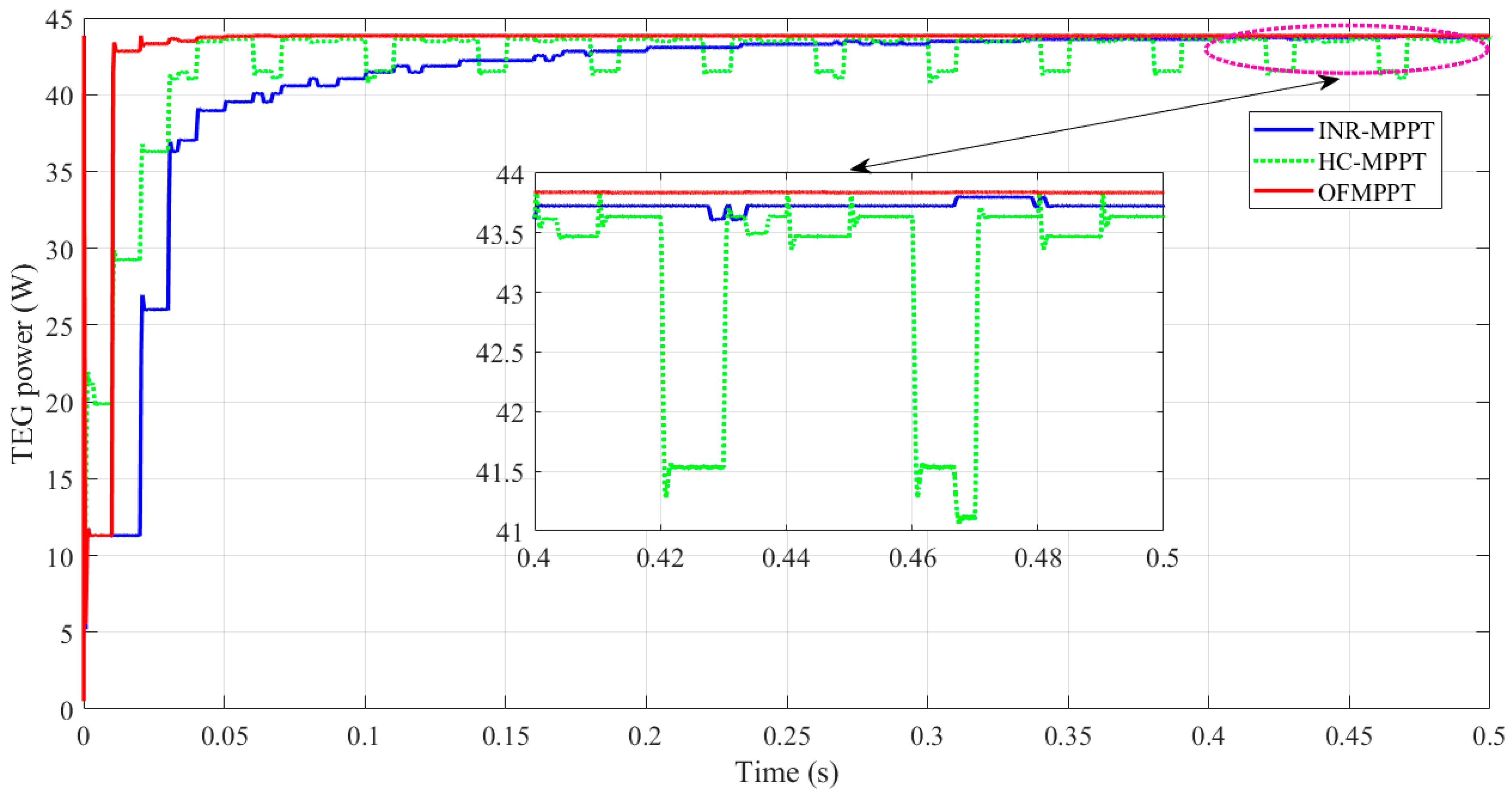
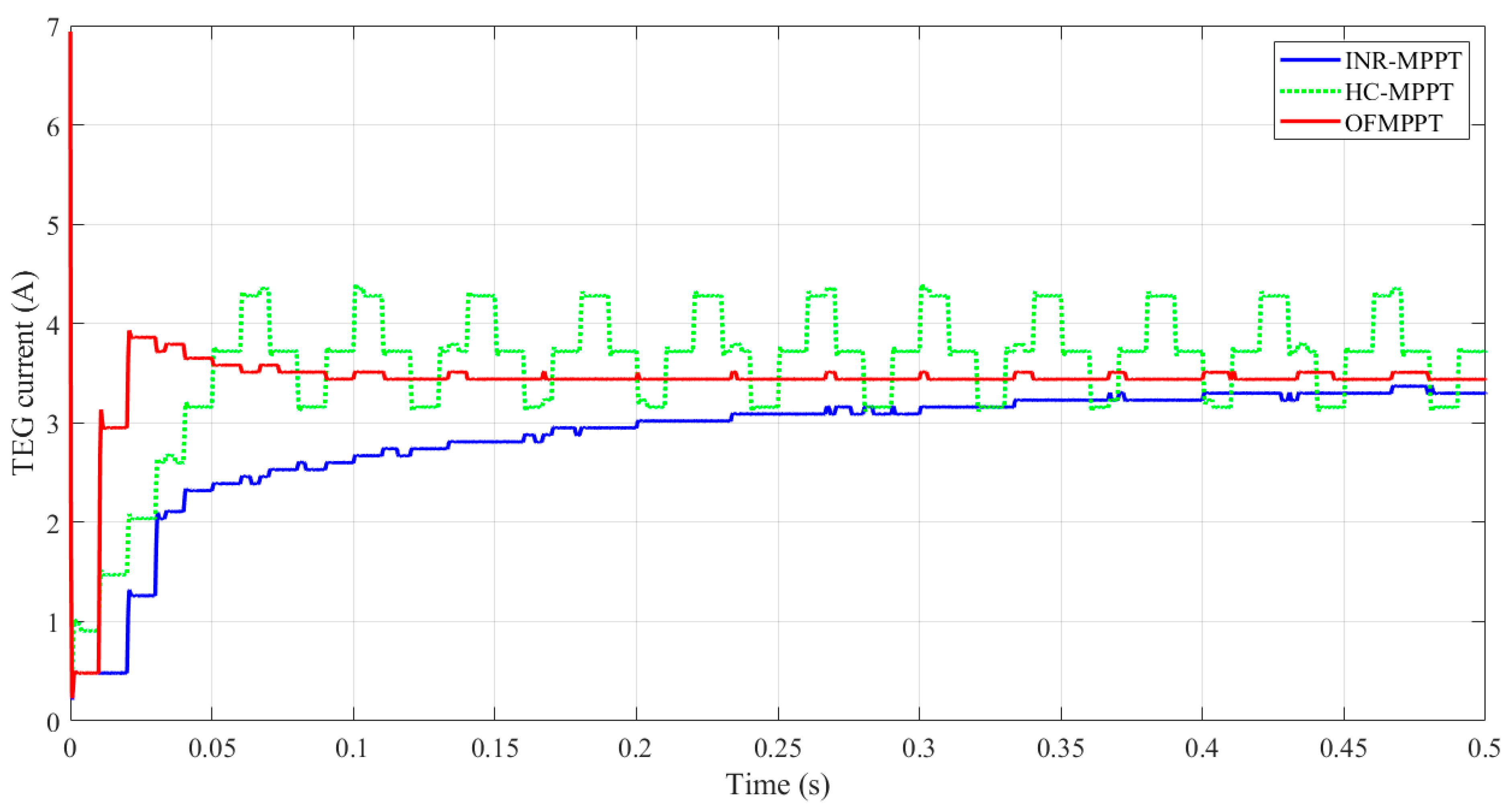
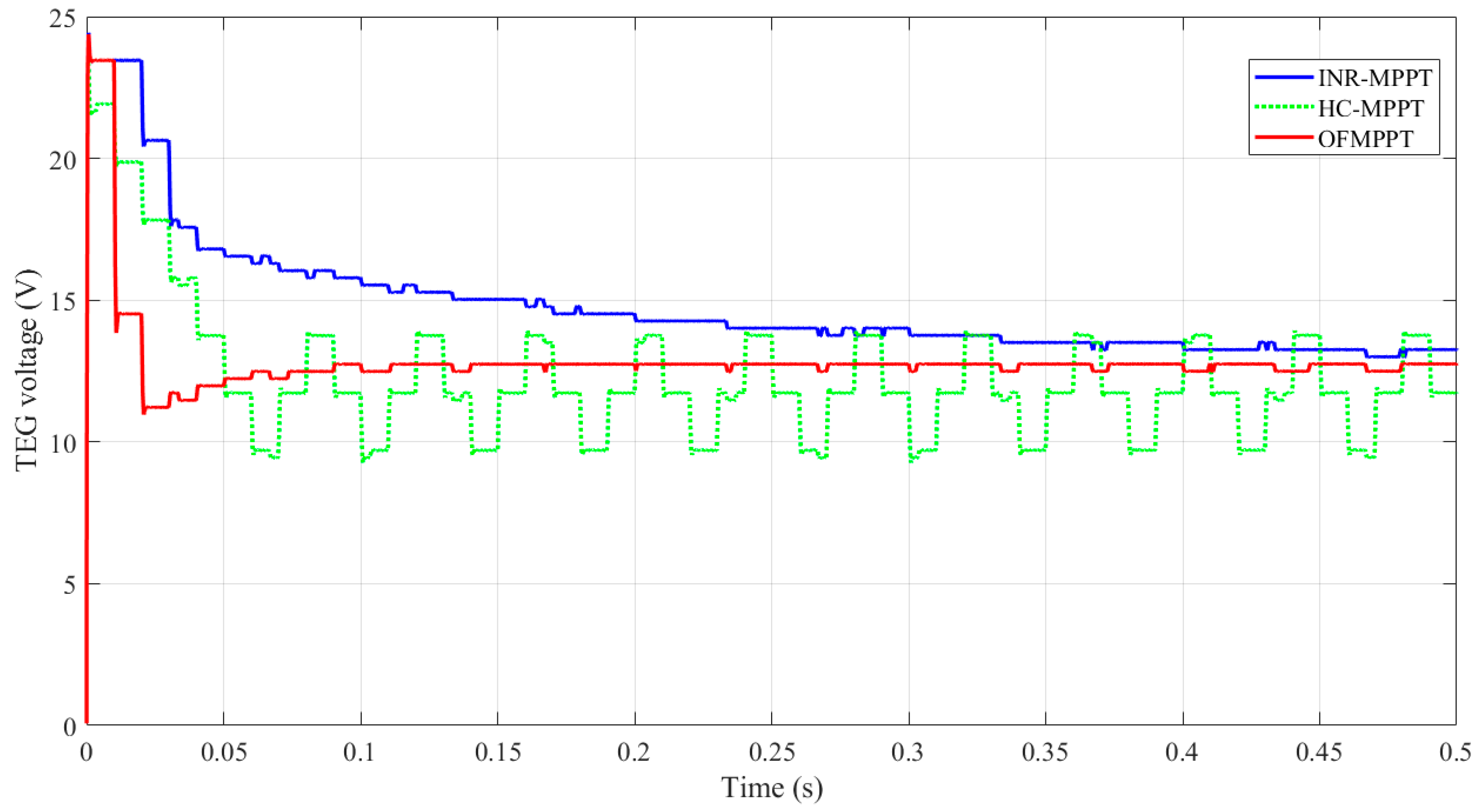
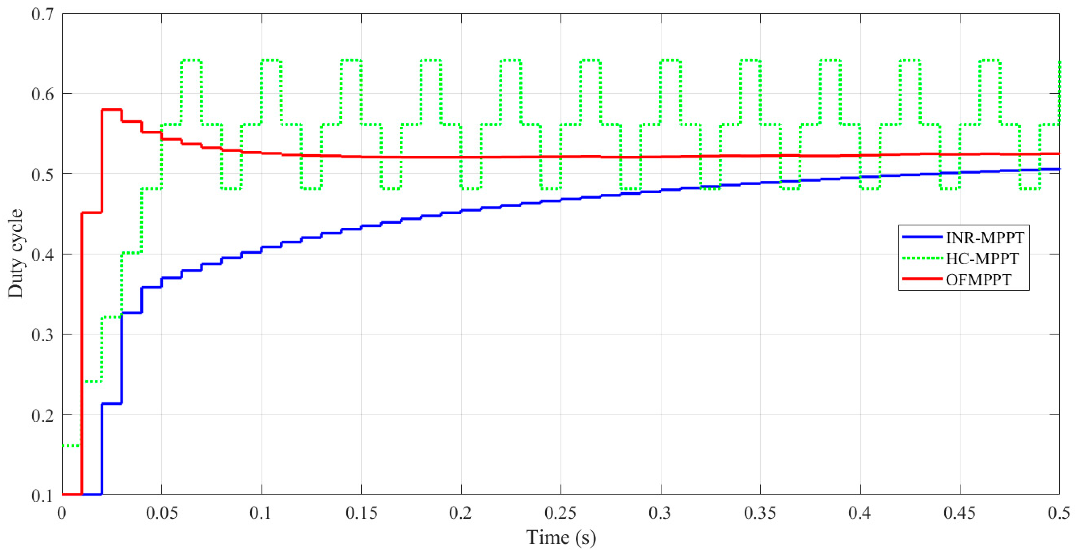
5. Results and Discussion

A Matlab code has been developed to investigate the TEG power as temperature differences change. In the simulations, the type of TEG (TEG1-12611-6.0) is used. The rated current, power, and voltage for a single TEG are 3.4 A, 4.2 V, and 14.6 W, respectively, with cold and hot-side temperatures of 30 and 300 °C, respectively. Figure 6a depicts the power against current of TEG as the hot-side temperature is varied while the cold temperature remains constant at 30 °C. In Figure 6a, Matlab’s model data are matched with datasets. Furthermore, the position of the MPP is primarily affected by temperature differences. Figure 6b indicates the power versus current of TEG while maintaining a hot temperature (300 °C) and altering the cold temperature. Every operation state has a unique MPP. To enhance the energy gained from the TEG, the MPPT must constantly follow the MPP, regardless of temperature and/or load demand. Figure 7 depicts the matched load parameters (voltage, power, resistance, and current) as the change in cold and hot temperatures.
To define the best paraments of OFMPPT, a hunger games search is used. The maximum number of iterations and the population size are set to 10 and 25, respectively. Throughout the parameter identification process, the objective function presented in (12) is maximized, whereas the unknown parameters of the OFMPPT are used as decision variables. The variation of the objective function during the optimization process is presented in Figure 8. The HGS optimizer needs around 15 iterations to reach the maximum objective function. The optimal values are 0.9, 0.0023, and 0.96, respectively, for the integration gain, proportional gain, and fractional order.
Once the best parameters for OFMPPT have been determined, the OFMPPT’s dynamic and steady state tracking performance is evaluated and compared to INR-MPPT and HC-MPPT. The Matlab TEG power systems for HC-MPPT, INR-MPPT, and OFMPPT are described in Figure 3, Figure 4 and Figure 5, respectively. The TEG power system consists of three TEG modules (total power 43.8 W), with cold and hot-side temperatures of 300 C and 30 C, respectively. The input inductance and output capacitor are 1 mH and 47 F, respectively, and there are three series batteries (total voltage is 21.6 V). The three MPPTs under consideration are used as a controller to provide a suitable duty cycle to the DC converter. The gain of the discrete integrator is set to 0.8 for the INR-MPPT. Moreover, the parameters of fractional PI for OFMPPT are 0.9, 0.0023, and 0.96 for the integration gain, proportional gain, and fractional order, as defined by HGS. The dynamic response of TEG power for HC-MPPT, INR-MPPT, and OFMPPT is shown in Figure 9. The proposed OFMPPT extracts the maximum power of 43.8 W in 0.07 s with no oscillations around the MPP. Moreover, the INR-MPPT takes approximately 0.33 s to catch the MPP. This means that using OFMPPT reduced tracking time by 78% when compared to INR-MPPT. On the other hand, HC-MPPT reaches the MPP in a short period of time; however, there are significant oscillations around the MPP. This demonstrated the OFMPPT’s superiority in tracking the MPP under both dynamic and steady state conditions. The resulting variations in TEG voltage, TEG current, and duty cycle are depicted in Figure 10, Figure 11 and Figure 12, respectively.
Considering Figure 10, at steady state, the TEG current value using OFMPPT is 3.4 A, which matched with datasheet of TEG1-12611-6.0, as shown in Figure 7.
Considering Figure 11, at steady state, the TEG voltage value using OFMPPT is 12.6 V (4.2 V for each TEG module), which matched with the datasheet of TEG1-12611-6.0, as shown in Figure 7.
Considering Figure 12, at steady state, the duty cycle value using OFMPPT is fixed at 0.52, whereas, using HC-MPPT, there are fluctuations around the MPP.

6. Conclusions

The best parameters for a single-sensor fractional maximum power point tracker for a thermoelectric generator have been identified. This paper accomplishes two major goals: reducing the number of sensors and improving tracking performance. The fractional control is used to improve the dynamic response of incremental resistance (INR-MPPT) and eliminate oscillations around the MPP when using the hill climbing (HC-MPPT) method. Three unknown parameters of optimized fractional (OFMPP); three parameters; proportional gain, integral gain, and fractional order must be correctly identified to ensure an improvement in tracking performance. The hunger games search is used to complete the parameter identification process. During the optimization process, the unknown parameters have been assigned as decision variables, whereas as the objective function is the harvested energy from the TEG. The results confirmed the superiority of OFMPPT in both transient and steady state compared to HC-MPPT and INR-MPPT. The proposed OFMPPT succeeded in extracting the maximum power of 43.8 W exactly and very quickly at 0.07 s and no oscillations were recorded around the MPP. Moreover, the INR-MPPT requires about 0.33 s to catch the MPP. This means that, when using OFMPPT, the tracking time decreased by 78% compared to INR-MPPT. On the other hand, HC-MPPT reached the MPP in a short amount time; however, there are high oscillations around the MPP. In future work, the OFMPPT will be used to extract the MPP of the hybrid photovoltaic/TEG system.

Author Contributions

Conceptualization, A.G.O., H.R. and M.A.A.; methodology H.R., E.T.S., T.A. and S.I.A.; formal analysis, E.T.S., T.A. and S.I.A.; investigation, S.I.A. and M.A.A.; resources, A.G.O. and S.I.A.; data curation, E.T.S. and T.A.; writing—original draft preparation, A.G.O., H.R., E.T.S., T.A., S.I.A. and M.A.A.; writing—review and editing, A.G.O., H.R., E.T.S., T.A., S.I.A. and M.A.A.; supervision, A.G.O. and M.A.A.; project administration, H.R. and E.T.S.; All authors have read and agreed to the published version of the manuscript.

Funding

This research was funded by Princess Nourah bint Abdulrahman University Researchers Supporting Project number (PNURSP2023R197), Princess Nourah bint Abdulrahman University, Riyadh, Saudi Arabia.

Institutional Review Board Statement

Not applicable.

Informed Consent Statement

Not applicable.

Data Availability Statement

Not applicable.

Acknowledgments

Princess Nourah bint Abdulrahman University Researchers Supporting Project number (PNURSP2023R197), Princess Nourah bint Abdulrahman University, Riyadh, Saudi Arabia.

Conflicts of Interest

The authors declare no conflict of interest.

References

  1. Olabi, A.G.; Wilberforce, T.; Elsaid, K.; Sayed, E.T.; Maghrabie, H.M.; Abdelkareem, M.A. Large scale application of carbon capture to process industries—A review. J. Clean. Prod. 2022, 362, 132300. [Google Scholar] [CrossRef]
  2. Olabi, A.G.; Wilberforce, T.; Sayed, E.T.; Shehata, N.; Alami, A.H.; Maghrabie, H.M.; Abdelkareem, M.A. Prospect of Post-Combustion Carbon Capture Technology and Its Impact on the Circular Economy. Energies 2022, 15, 8639. [Google Scholar] [CrossRef]
  3. Lyu, L.; Chen, W.; Kan, A.; Zhang, Y.; Xue, S.; Zeng, J. Investigation of a Dual-Loop ORC for the Waste Heat Recovery of a Marine Main Engine. Energies 2022, 15, 8365. [Google Scholar] [CrossRef]
  4. Olabi, A.G.; Al-Murisi, M.; Maghrabie, H.M.; Yousef, B.A.A.; Sayed, E.T.; Alami, A.H.; Abdelkareem, M.A. Potential applications of thermoelectric generators (TEGs) in various waste heat recovery systems. Int. J. Thermofluids 2022, 16, 100249. [Google Scholar] [CrossRef]
  5. Brough, D.; Jouhara, H. The aluminium industry: A review on state-of-the-art technologies, environmental impacts and possibilities for waste heat recovery. Int. J. Thermofluids 2020, 1–2, 100007. [Google Scholar] [CrossRef]
  6. Jouhara, H.; Żabnieńska-Góra, A.; Khordehgah, N.; Doraghi, Q.; Ahmad, L.; Norman, L.; Axcell, B.; Wrobel, L.; Dai, S. Thermoelectric generator (TEG) technologies and applications. Int. J. Thermofluids 2021, 9, 100063. [Google Scholar] [CrossRef]
  7. Sayed, E.T.; Abdelkareem, M.A.; Bahaa, A.; Eisa, T.; Alawadhi, H.; Al-Asheh, S.; Chae, K.-J.; Olabi, A.G. Synthesis and performance evaluation of various metal chalcogenides as active anodes for direct urea fuel cells. Renew. Sustain. Energy Rev. 2021, 150, 111470. [Google Scholar] [CrossRef]
  8. Sayed, E.T.; Abdelkareem, M.A.; Alawadhi, H.; Olabi, A.G. Enhancing the performance of direct urea fuel cells using Co dendrites. Appl. Surf. Sci. 2021, 555, 149698. [Google Scholar] [CrossRef]
  9. Salameh, T.; Sayed, E.T.; Abdelkareem, M.A.; Olabi, A.G.; Rezk, H. Optimal selection and management of hybrid renewable energy System: Neom city as a case study. Energy Convers. Manag. 2021, 244, 114434. [Google Scholar] [CrossRef]
  10. Olabi, A.G.; Wilberforce, T.; Elsaid, K.; Salameh, T.; Sayed, E.T.; Husain, K.S.; Abdelkareem, M.A. Selection Guidelines for Wind Energy Technologies. Energies 2021, 14, 3244. [Google Scholar] [CrossRef]
  11. Abdelkareem, M.A.; Maghrabie, H.M.; Sayed, E.T.; Kais, E.-C.A.; Abo-Khalil, A.G.; Radi, M.A.; Baroutaji, A.; Olabi, A.G. Heat pipe-based waste heat recovery systems: Background and applications. Therm. Sci. Eng. Prog. 2022, 29, 101221. [Google Scholar] [CrossRef]
  12. Wilberforce, T.; Olabi, A.; Muhammad, I.; Alaswad, A.; Sayed, E.T.; Abo-Khalil, A.G.; Maghrabie, H.M.; Elsaid, K.; Abdelkareem, M.A. Recovery of waste heat from proton exchange membrane fuel cells–A review. Int. J. Hydrogen Energy, 2022; in press. [Google Scholar] [CrossRef]
  13. He, W.; Zhang, G.; Zhang, X.; Ji, J.; Li, G.; Zhao, X. Recent development and application of thermoelectric generator and cooler. Appl. Energy 2015, 143, 1–25. [Google Scholar] [CrossRef]
  14. Jiang, B.; Wang, W.; Liu, S.; Wang, Y.; Wang, C.; Chen, Y.; Xie, L.; Huang, M.; He, J. High figure-of-merit and power generation in high-entropy GeTe-based thermoelectrics. Science 2022, 377, 208–213. [Google Scholar] [CrossRef] [PubMed]
  15. Zilber, T.; Cohen, S.; Fuks, D.; Gelbstein, Y. TiNiSn half-Heusler crystals grown from metallic flux for thermoelectric applications. J. Alloys Compd. 2019, 781, 1132–1138. [Google Scholar] [CrossRef]
  16. Meroz, O.; Gelbstein, Y. Thermoelectric Bi2Te3−xSex alloys for efficient thermal to electrical energy conversion. Phys. Chem. Chem. Phys. 2018, 20, 4092–4099. [Google Scholar] [CrossRef]
  17. Qiu, P.; Cheng, J.; Chai, J.; Du, X.; Xia, X.; Ming, C.; Zhu, C.; Yang, J.; Sun, Y.-Y.; Xu, F.; et al. Exceptionally Heavy Doping Boosts the Performance of Iron Silicide for Refractory Thermoelectrics. Adv. Energy Mater. 2022, 12, 2200247. [Google Scholar] [CrossRef]
  18. Coelho, R.; Casi, Á.; Araiz, M.; Astrain, D.; Branco Lopes, E.; Brito, F.P.; Gonçalves, A.P. Computer Simulations of Silicide-Tetrahedrite Thermoelectric Generators. Micromachines 2022, 13, 1915. [Google Scholar] [CrossRef]
  19. Wang, J.; Cao, P.; Li, X.; Song, X.; Zhao, C.; Zhu, L. Experimental study on the influence of Peltier effect on the output performance of thermoelectric generator and deviation of maximum power point. Energy Convers. Manag. 2019, 200, 112074. [Google Scholar] [CrossRef]
  20. Yang, B.; Zhang, M.; Zhang, X.; Wang, J.; Shu, H.; Li, S.; He, T.; Yang, L.; Yu, T. Fast atom search optimization based MPPT design of centralized thermoelectric generation system under heterogeneous temperature difference. J. Clean. Prod. 2020, 248, 119301. [Google Scholar] [CrossRef]
  21. Aly, M.; Rezk, H. A MPPT based on optimized FLC using manta ray foraging optimization algorithm for thermo-electric generation systems. Int. J. Energy Res. 2021, 45, 13897–13910. [Google Scholar] [CrossRef]
  22. Rezk, H.; Harrag, A. A robust type-2 fuzzy logic-based maximum power point tracking approach for thermoelectric generation systems. Int. J. Energy Res. 2021, 45, 18066–18080. [Google Scholar] [CrossRef]
  23. Ahmed, E.M.; Shoyama, M. Scaling factor design based variable step size incremental resistance maximum power point tracking for PV systems. J. Power Electron. 2012, 12, 164–171. [Google Scholar] [CrossRef] [Green Version]
  24. Kanagaraj, N. Design and performance evaluation of fuzzy variable fractional-order [PI] λDµ controller for a class of first-order delay-time systems. Stud. Inform. Control 2019, 28, 443–452. [Google Scholar] [CrossRef]
  25. Delavari, H.; Lanusse, P.; Sabatier, J. Fractional Order Controller Design for A Flexible Link Manipulator Robot. Asian J. Control. 2013, 15, 783–795. [Google Scholar] [CrossRef]
  26. Qasim, M.A.; Alwan, N.T.; Praveen Kumar, S.; Velkin, V.I.; Agyekum, E.B. A New Maximum Power Point Tracking Technique for Thermoelectric Generator Modules. Inventions 2021, 6, 88. [Google Scholar] [CrossRef]
  27. Bijukumar, B.; Raam, A.G.K.; Ilango Ganesan, S.; Nagamani, C.; Reddy, M.J.B. MPPT algorithm for thermoelectric generators based on parabolic extrapolation. IET Gener. Transm. Distrib. 2019, 13, 821–828. [Google Scholar] [CrossRef]
  28. Park, J.-D.; Lee, H.; Bond, M. Uninterrupted thermoelectric energy harvesting using temperature-sensor-based maximum power point tracking system. Energy Convers. Manag. 2014, 86, 233–240. [Google Scholar] [CrossRef]
  29. Cokmez, E.; Atiç, S.; Peker, F.; Kaya, I. Fractional-order PI Controller Design for Integrating Processes Based on Gain and Phase Margin Specifications. IFAC-PapersOnLine 2018, 51, 751–756. [Google Scholar] [CrossRef]
  30. Yang, Y.; Chen, H.; Heidari, A.A.; Gandomi, A.H. Hunger games search: Visions, conception, implementation, deep analysis, perspectives, and towards performance shifts. Expert Syst. Appl. 2021, 177, 114864. [Google Scholar] [CrossRef]
Figure 1. TEG system’s power stage with the suggested MPPT controller.
Sustainability 15 05054 g001
Figure 2. (a) General overview of TEG, (b) P-type and N-type groups, and (c) simple equivalent-circuit of the TEG.
Sustainability 15 05054 g002
Figure 3. Matlab model of single-sensor HC-MPPT.
Sustainability 15 05054 g003
Figure 4. Matlab model of single-sensor INR.
Sustainability 15 05054 g004
Figure 5. Matlab model of single-sensor OFMPPT.
Sustainability 15 05054 g005
Figure 6. TEG power against TEG current: (a) altering the hot temperature while maintaining cold temperature at 30 C and (b) altering cold temperature while maintaining hot temperature at 300 °C.
Sustainability 15 05054 g006
Figure 7. Matched load parameters.
Sustainability 15 05054 g007
Figure 8. Variation of the objective function.
Sustainability 15 05054 g008
Figure 9. TEG power response during tracking the MPP.
Sustainability 15 05054 g009
Figure 10. TEG current response while tracking the MPP.
Sustainability 15 05054 g010
Figure 11. TEG voltage response while tracking the MPP.
Sustainability 15 05054 g011
Figure 12. Duty cycle response while tracking the MPP.
Sustainability 15 05054 g012
Disclaimer/Publisher’s Note: The statements, opinions and data contained in all publications are solely those of the individual author(s) and contributor(s) and not of MDPI and/or the editor(s). MDPI and/or the editor(s) disclaim responsibility for any injury to people or property resulting from any ideas, methods, instructions or products referred to in the content.

