Article

Analysis of the Levelized Cost of Renewable Hydrogen in Austria

by
Leonhard Povacz
* and
Ramchandra Bhandari
*
Institute for Technology and Resources Management in the Tropics and Subtropics (ITT), Technische Hochschule Köln, University of Applied Sciences, Betzdorfer Strasse 2, 50679 Cologne, Germany
*
Authors to whom correspondence should be addressed.
Sustainability 2023, 15(5), 4575; https://doi.org/10.3390/su15054575
Submission received: 24 January 2023 / Revised: 27 February 2023 / Accepted: 1 March 2023 / Published: 3 March 2023
(This article belongs to the Section Energy Sustainability)

Abstract

:
Austria is committed to the net-zero climate goal along with the European Union. This requires all sectors to be decarbonized. Hereby, hydrogen plays a vital role as stated in the national hydrogen strategy. A report commissioned by the Austrian government predicts a minimum hydrogen demand of 16 TWh per year in Austria in 2040. Besides hydrogen imports, domestic production can ensure supply. Hence, this study analyses the levelized cost of hydrogen for an off-grid production plant including a proton exchange membrane electrolyzer, wind power and solar photovoltaics in Austria. In the first step, the capacity factors of the renewable electricity sources are determined by conducting a geographic information system analysis. Secondly, the levelized cost of electricity for wind power and solarphotovoltaics plants in Austria is calculated. Thirdly, the most cost-efficient portfolio of wind power and solar photovoltaics plants is determined using electricity generation profiles with a 10-min granularity. The modelled system variants differ among location, capacity factors of the renewable electricity sources and the full load hours of the electrolyzer. Finally, selected variables are tested for their sensitivities. With the applied model, the hydrogen production cost for decentralized production plants can be calculated for any specific location. The levelized cost of hydrogen estimates range from 3.08 EUR/kg to 13.12 EUR/kg of hydrogen, whereas it was found that the costs are most sensitive to the capacity factors of the renewable electricity sources and the full load hours of the electrolyzer. The novelty of the paper stems from the model applied that calculates the levelized cost of renewable hydrogen in an off-grid hydrogen production system. The model finds a cost-efficient portfolio of directly coupled wind power and solar photovoltaics systems for 80 different variants in an Austria-specific context.

1. Introduction

Austria aims to become climate-neutral by 2040. To reach this target, it is necessary to decarbonize all sectors. Hereby, the production of renewable hydrogen is considered to be essential as stated in the national hydrogen strategy along with the European Commission (EC) [1,2]. Therefore, the Austrian government has set an intermediate goal to replace 80% of the consumption of fossil-generated hydrogen in the energy-intensive industry (energy and non-energy use) with climate-neutral hydrogen by 2030. Theoretically, this can be accomplished using a total installed capacity of 1 GW electrolysis. Assuming an operation of around 5000 full-load hours per year, this electrolysis capacity can largely cover the current industrial demand for hydrogen in Austria [1]. Additionally, a report that has been commissioned by the Austrian government predicts a minimum hydrogen demand of 16 TWh per year in Austria in 2040, which emphasizes the need for future domestic hydrogen production [3].
In view of the statements above, this study analyses the levelized cost of renewable hydrogen produced in decentralized small-scale systems with directly coupled wind power (WP) and solar photovoltaics (PV). The results of this study serve as a prefeasibility analysis to support the investment decisions of public and private companies that demand renewable hydrogen now and in future scenarios. For investors, such systems pose advantages such as the flexibility in the choice of location and therefore the option to build the system close to where hydrogen is demanded in order to reduce transportation as well as storage costs [4]. Furthermore, island systems confront fewer obstacles in project realization in terms of regulation and the proposed system can be installed in areas where infrastructure and, hence, grid connection (electrical grid and/or gas grid) is not available [1].
In principle, the analysis includes four steps:
  • The determination of the capacity factors (Cf) of WP (Cf-WP) and Cf of PV (Cf-PV) in Austria by conducting a geographic information system (GIS) analysis;
  • The analysis of the levelized cost of electricity (LCOE) for these two renewable electricity (REL) sources;
  • The analysis of the levelized cost of hydrogen (LCOH) for the predefined system design using electrical feed-in profiles based on real weather data;
  • A sensitivity analysis of the techno-economic input parameters for the calculation of the LCOH.
The model is applied for 80 different system variants, which vary among capacity factors of the renewable electricity sources (REL-Cf), the full load hours (PEM-FLH) of the proton exchange membrane (PEM) electrolyzer as well as location and thus electricity generation profiles (EGP). The model finds the most cost-efficient addition of REL-plants based on the assumptions made. These three variables, as well as selected economic input parameters, are further analyzed in a sensitivity analysis that shows how a change in variables impacts the present cost as well as the potential future price of renewable hydrogen.
The results of this paper ought to be interpreted as one option to provide hydrogen to decarbonize processes and should therefore be compared to other options such as a change in production routes, hydrogen imports or alternative energy sources. Hence, this paper addresses the following questions:
  • What is the levelized cost of renewable hydrogen in Austria given the proposed system design?
  • What are the levelized costs of electricity for WP and PV in Austria and how are the qualities of sites distributed throughout the country?
  • How do changes in techno-economic input parameters affect the cost for renewable hydrogen?
The paper’s novelty lies in its use of a model that computes the LCOH in an off-grid hydrogen production system, which incorporates a cost-effective portfolio of WP and PV systems that are directly coupled to an electrolyzer. The REL-Cf are calculated by a thorough GIS analysis in an Austria-specific context. The model computes results for 80 system variants that vary in terms of their electricity generation profile, the capacity factors of the connected REL sources and the yearly output of hydrogen from the production facility.
This paper continues with the justification of the research gap and a literature review in the upcoming paragraphs/subsections. It includes an outlook for a hydrogen market in Austria and the European Union (EU) as well as a description of the renewable hydrogen production system modelled. Further on, findings of previous research in the field of renewable hydrogen are presented. In continuation, a study about the projected hydrogen demand up until 2040 is introduced. This is followed by the materials/method section. Afterward, the results and the sensitivity analysis are presented and discussed. The paper finishes with a conclusion and an outlook for future studies.

1.1. Hydrogen Prospects in Austria and the European Union

Globally, 90% of the hydrogen consumed is used as industrial feedstock. Hereby, the ammonia industry, the petrol industry (for the production of methanol and for the refining of crude oil) as well as new applications in the low-carbon steel industry make up the biggest share of hydrogen consumption [5]. In order to decarbonize these processes, the EC set the goal of 40 GW of electrolysis capacity by 2030 [2]; at the same time, some member states have stated national goals (Germany 5 GW [6], France 6.5 GW [7], Netherlands 3 to 4 GW [8], Italy 5 GW [9]). The production of hydrogen is closely related to the creation of a hydrogen market. Hereby, the EC plans as part of the Green Deal Industrial Plan to simplify the regulatory environment for permission for strategic projects, speed up access to funding, invest in relevant education and open the trade network for resilient supply chains [10]. Additionally, policymakers have set goals and a regulatory framework on a national level, as 17 member states of the EU have already introduced a national hydrogen strategy [11]. The strategic positioning of European countries in the context of a hydrogen market differs. Poland states in course of its national hydrogen strategy to integrate hydrogen technologies in the energy sector, use it as a viable alternative fuel in transportation and seeks to support the decarbonization of the industry. Other key initiatives include the establishment of new hydrogen production facilities, the development of efficient and safe transportation methods and the creation of a stable regulatory environment to facilitate market growth [12,13]. Germany secures bilateral partnerships for hydrogen imports as it does not hold the renewable resources to cover its domestic demand but wants to become an exporter of hydrogen technology. For use application, the emphasis is on chemical, petrochemical and steelmaking industries together with heavy transport [6,14]. The strategy of the UK focuses on increasing the production, distribution and use of low-carbon hydrogen across various sectors, including industry, transport and heating. The government is also investing in research and development, infrastructure and regulatory framework to support the deployment of hydrogen technology [15]. Italy identifies public transportation, chemical and refining as crucial sectors for the use and development of hydrogen. In addition, due to its strategic location in the Mediterranean, the country has the potential to serve as a pivotal point for the hydrogen market, positioned between potential major exporters in Africa and the Middle East and consumers in Northern Europe. Hence, Italy is fostering research and development in blending hydrogen into the existing natural gas pipeline network [9,16]. Ireland, on the other hand, is still in the process of publishing a hydrogen strategy. The application of hydrogen is primarily targeted toward hard-to-abate areas, which include electricity production, industry (including industrial heating) and transportation sectors (such as heavy-duty vehicles, maritime vessels and aviation) [17]. In terms of supply, stakeholders suggest supplying the electrolyzers with a mix of curtailed WP and power drawn from the grid [18]. On a business level, industries foster hydrogen projects individually and in economic compounds, in particular the European Hydrogen Backbone that involves Austrian companies and that invests in research and development of a hydrogen infrastructure throughout Europe [19]. Utility scale applications for renewable hydrogen hold potential for a market ramp-up [20], whereas Austria intends to focus on processes that go beyond the foreseeable economically and technically achievable capacities of battery systems and possibilities for direct electrification, such as energy-intensive industries that demand hydrogen as a chemical compound and energy carrier, injection in the existing natural gas grid as well as heavy transport [1,21]. Furthermore, according to the national hydrogen strategy, Austria wants to investigate the application of decentralized complete solutions for regions where alternatives are not available due to a lack of grid infrastructure [1]. However, these applications confront obstacles such as the still-high investment costs of system components, the technical implementation, the regulatory framework as well as the capacity of the electrical grid [1,20,21].
Today, the hydrogen supply in Austria is almost exclusively provided by fossil-based production [1]. In Ref. [3], the authors quantify the demand for natural gas and renewable gas, respectively, in Austria up until 2040. Hereby, the study distinguishes among methane demand that is not substitutable, gas demand that can be covered by hydrogen or methane and, finally, demand for hydrogen only. The “Infrastructure Utilization” scenario represents a continuation of current gas use to the greatest possible extent. Differently to that, the development of the industry in the “Exergy Efficiency” scenario can be described by ambitious technological progress and the consistent use of new exergy-efficient technologies that are optimally adapted to the required temperature and process parameters in the respective sectors [3]. As illustrated in Figure 1, the predicted hydrogen demand of 16 TWh to 25 TWh per year highlights the need to exploit the possibilities of domestic hydrogen production. The authors conclude that the sole supply of biogenic gases will not cover the demand for green gases in 2040 for the sectors examined (even without the building sector, without motorized private transport and without grid reserve). The further demand must therefore be met by domestically produced renewable hydrogen and synthetic methane based on it, as well as by imports [3].

1.2. Definition of Renewable Hydrogen and the Followed System Design

The EC has published a draft for a delegated regulation on the production of renewable transport fuels and the required share of renewable electricity [22]. In this draft, the EC distinguishes among ways to produce renewable hydrogen, whereas the present study analyzes a system according to the “Rules for counting electricity sourced from directly connected installations as fully renewable”. According to the EC [22], the following evidence must be provided by the producer:
  • Direct coupling: “the installations generating renewable electricity are connected to the installation producing renewable liquid and gaseous transport fuel of non-biological origin via a direct line, or the renewable electricity production and production of renewable liquid and gaseous transport fuel of non-biological origin take place within the same installation” [22];
  • Additionality: “the installations generating renewable electricity came into operation not earlier than 36 months before the installation producing renewable liquid and gaseous transport fuel of non-biological. Where additional production capacity is added to an existing installation producing renewable liquid and gaseous transport fuel of non-biological origin, the added capacity shall be considered to be part of the existing installation, provided that the capacity is added at the same site and the addition takes place no later than 24 months after the initial installation came into operation” [22];
  • No grid connection: “the installation producing electricity is not connected to the grid, or the installation producing electricity is connected to the grid but a smart metering system that measures all electricity flows from the grid shows that no electricity has been taken from the grid to produce renewable liquid and gaseous transport fuel of nonbiological origin” [22].
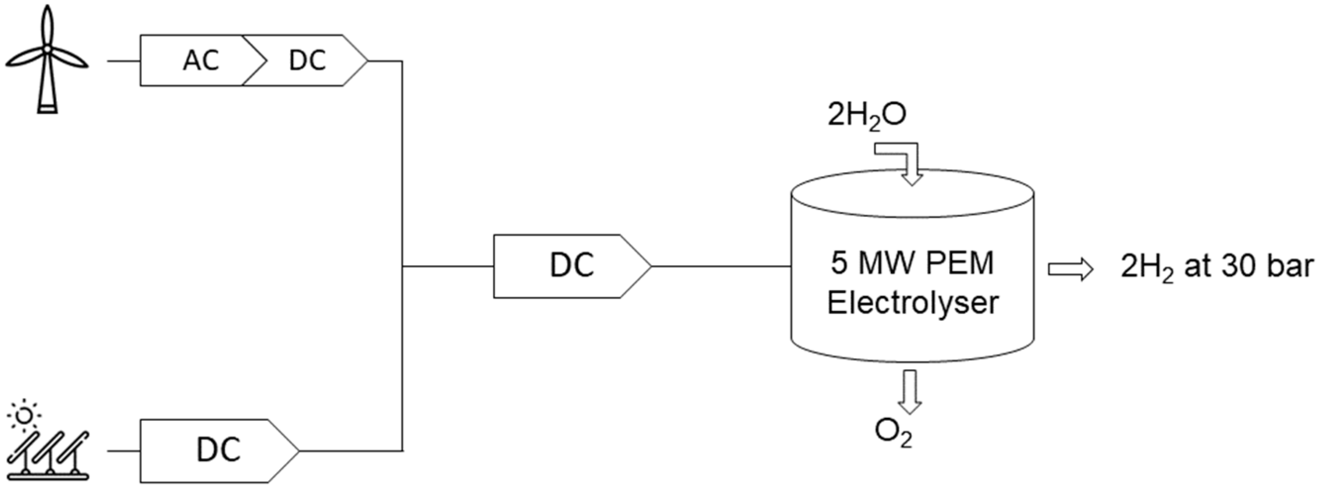
Therefore, this study models an off-grid system with the REL-sources directly coupled to the electrolyzer that meets all above-mentioned criteria. The modelled hydrogen production system is aligned with the EC criteria of declaring the hydrogen as renewable [22], it follows the goal of the Austrian hydrogen strategy in investigating the application of off-grid systems [1] and follows the targets of the Renewable Energy Expansion Act (EAG) [23]; as for the connected REL-sources, WP and PV are considered, which the Austrian government focuses on for future REL-capacities as part of the EAG. With this legislation, the country plans to cover 100% of the domestic electricity demand with REL-sources in 2030. This implies an additional production capacity of 27 TWh by 2030, whereas 11 TWh ought to be covered from PV, 10 TWh are planned for WP, 5 TWh will be covered by additional hydropower and the remaining 1 TWh from biomass [23]. As it is planned that WP and PV plants will cover 77.7% of the newly installed capacities by 2030, these two technologies are predestined to fulfill the additionality criteria for renewable hydrogen required by the EC [22], as it is assumed that WP and PV are more accessible for investors of small-scale off-grid hydrogen production systems than hydropower [24]. Furthermore, the analysis only considers a PEM electrolyzer, as it can be integrated into a system with volatile REL sources such as WP and PV due to its capability to operate under flexible load [25]. For the hydrogen production plant, the installed capacity of the PEM electrolyzer is fixed to an output capacity of 5 MW. The input capacity—which results from the division of the output capacity by the efficiency of the electrolyzer of 70%—is roughly 7.14 MW. The electrolyzer is directly coupled to WP and/or PV systems depending on the variant modelled. The cost for the produced hydrogen is calculated at the nozzle with a pressure of 30 bar. Figure 2 shows a scheme of the production plant.
For directly coupled systems, the operating mode is determined by the full load hours of the connected REL-plant and can therefore be defined as a supply-oriented operation [21]. The applied model is adding WP and PV capacities, respectively, to each system variant most cost-efficient to reach a predefined amount of PEM-FLH. A lack of electricity cannot be balanced by other sources of electricity (absorption of electricity from the public grid, participation in congestion management, participation in the balancing energy market) as the system is off-grid. The excess energy generated, i.e., electrical energy that exceeds the input capacity of the electrolyzer, is not used in this system [21].

1.3. Current Research Status

As the results of this study are compared to that of the current research in this field, there seem to be large differences in the LCOH. This is due to the differing assumptions authors take when calculating the LCOH. Table 1 lists selected recent literature, its fundamental assumptions and system design, the calculated LCOH as well as the geographic region and the year for which the respective LCOH is found. Hereby, as the current study analyses the LCOH for renewable hydrogen only, studies or results with a focus on fossil-based hydrogen are not considered in this literature research. The values found range from a minimum of 1.8 EUR/kg hydrogen to a maximum of 57.61 EUR/kg hydrogen.
While LCOH analysis for both off-grid systems [4,21,26,31,33,34] as well as grid-connected systems [4,21,27,28,29,30] has been conducted in other studies, little research is available for the optimal REL-portfolio in a hydrogen production system that includes PV and WP in Austria. Tang et al. [32] carried out a similar analysis for Sweden. However, the authors in [32] conducted the analysis with EGPs with a granularity of 1 h, as opposed to this study that includes a 10-min granularity. Further on, the current study determines the REL-Cf using climate data as part of a GIS-analysis, rather than using recent yearly averages and includes a range of REL-Cf and its effect on the REL-portfolio as well as the impact on the LCOH. Additionally, the GIS-analysis allows the detection of feasible sites within the study area. Finally, the present study compares various generation profiles and hence the compatibility of PV and WP in decentralized hydrogen production systems.

2. Materials and Methods

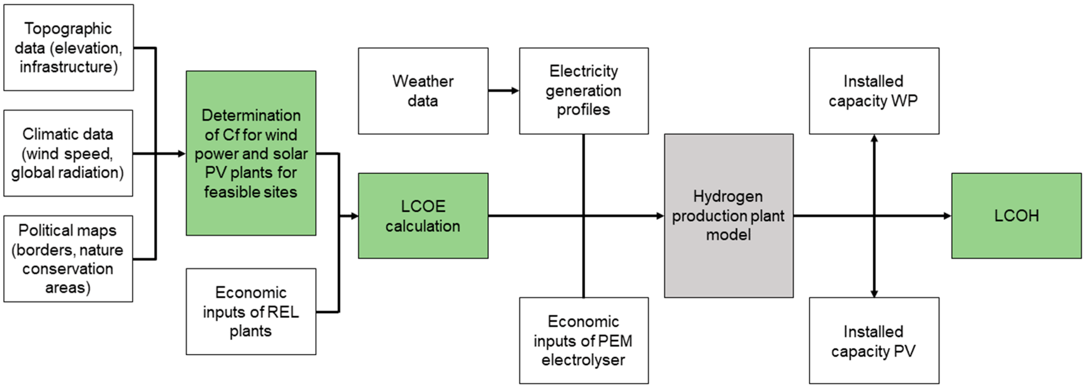
The main target of this work is the calculation of the LCOH of a proposed decentralized renewable hydrogen production plant. The conducted analysis includes three main steps. The results of these steps are highlighted in Figure 3 in green. This shows a scheme of the general approach for the calculation of the LCOH. The main data components, its usage in the analysis and the data sources are listed in Table 2.

2.1. Cf-WP for Selected Sites

The spatial planning in Austria lies within the sphere of competence of the nine federal states. This results in a heterogenous and highly complex regulatory framework for the realization WP projects [52]. As this study covers all of Austria and not one single state, a conservative approach has been chosen to determine feasible sites for WP. The applied restrictions as well as the respective sources for the GIS data are summarized in Table 3. The excluded areas are subtracted from the total area of Austria.
With the use of a power curve [53] and average wind speed distributions, the Cf-WP at hub heights of 50 m, 100 m and 150 m are determined for the remaining areas in Austria. For this calculation, the applied power curve is scaled according to the site and hub-height-specific air density following the IEC 61400-12-1:2017 standard [54].

2.2. Cf-PV for Selected Sites

In principle, the positioning of utility scale PV plants confronts fewer limitations than wind energy. PV is less visible, less noisy and does not create intermittent shades. Therefore, feasible sites for PV plants are detected in this study by setting parameters that represent a probable social acceptance rather than technical feasibility. High social acceptance for utility scale PV plants can be expected along roads, already sealed areas such as parking lots or industries, areas with soil of low agricultural quality or any other areas that do not conflict with other use [55]. Hence, the EU land use map [38] has been filtered by the criteria listed in Table 4 to detect suitable locations. This sample of locations has been further filtered to contiguous areas at or over 16,000 m2, as defined as the minimum area for an installed capacity of a 1 MW PV plant [55]. Category 1 areas represent areas that are expected to encounter fewer conflicts with alternative use. Category 2 areas, however, are of agricultural value. Therefore, Category 2 areas are only considered in this study if located along the infrastructural network, including main roads and railways, with a buffer of 500 m. These areas are expected to be available with probable social acceptance and lower costs [55].
For the Cf-PV, the Global Solar Atlas provides a detailed analysis for the entire world using standardized PV system installations [40]. For this study, the values with a resolution of yearly averages in kWh/kWp are used.

2.3. LCOE for WP and PV in Austria

The levelized cost of electricity is calculated by comparing all costs incurred over the lifetime of a power plant, including its CAPEX, its variable as well as its fixed OPEX, with the total amount of energy produced by the power plant throughout the operating time (Equation (1)) [44,56].
L C O E = I 0 + t = 1 n A t 1 + i t t = 1 n M t 1 + i t
where I0 is CAPEX; t is the targeted temporal interval; n is the number of temporal intervals; A is variable and fixed OPEX; M is the electrical energy produced and i is the discount factor.
The economic parameters, i.e., CAPEX, variable and fixed OPEX and the discount rate, have been determined by conducting a literature research. Table 5 and Table 6, respectively, show the values that are used to calculate the LCOE for WP and for PV, respectively.
The LCOE is determined for all relevant sites for both REL-technologies with the use of the respective Cf. The results are then further classified, whereas for each technology, classes with a step of 10 EUR are determined by the respective Cf-steps. Further on, the number of data points per class, technology and hub height are counted. Out of these results, an LCOE-range for the respective technology in Austria is determined.

2.4. Generation Profiles of WP and PV

The generation profiles for WP and PV, respectively, are based on real weather data from Ref. [51]. Both the wind speed data as well as the solar radiation data have a 10-min granularity and therefore 52,560 data points per year.
As a representative weather year, the year 2018 is chosen. For this study, the four locations listed in Table 7 are selected.
Figure 4 displays the wind speed distribution and the global radiation distribution, respectively, for Zwerndorf [51]. The PV distributions have a strong seasonal pattern, whereas the WP distributions show a more intermittent profile.
All distributions are plotted to their 10-min and monthly frequency, respectively, as shown in Figure 5. The four locations differ considerably in terms of wind speed distribution for both the daily and monthly values. In opposition to that, the comparison of PV patterns shows fewer differences among locations.
The wind speed frequencies of the Zwerndorf, Galtuer and Neumarkt locations are significantly elevated during daytime hours. This is particularly true for the Neumarkt location. Differently to that, Kremsmuenster shows the most uniform 10-min wind speed frequency. As PV produces the most electricity during the summer months, the pattern of Kremsmuenster is considered beneficial if coupling WP sources with PV sources directly to an electrolyzer [32].
In reference to the daily patterns above, a monthly wind speed frequency distribution is considered beneficial if wind occurs more often in the winter months (Figure 6), as PV produces a high share of electricity during the summer months [32]. Hereby, Zwerndorf shows the best monthly pattern, followed by Kremsmuenster. Compared to that, Galtuer and Neumarkt have higher shares of wind speed during the summer months and lower shares in the winter months, which is considered less complementary to the patterns of PV [32].
Both the WP and the PV generation profiles are scaled to the Cf of the respective system variant. The wind speed data and the global radiation data, respectively, of each weather station from Ref. [51] define the annual distribution. Hereby, each of the 52,560 data points are divided by the yearly accumulated wind speed and global radiation, respectively. In a subsequent step, the data points are scaled by means of the respective annual average. Hereby, the annual average is set to exactly the value that results in the targeted REL-Cf for the respective system variant. The result is a feed-in profile for each REL-source based on real weather data, scaled to a predefined REL-Cf.

2.5. Calculation of the LCOH

In principle, the calculation of the LCOH is carried out analogously to the calculation of the LCOE. In the following, the economic assumptions for the electrolyzer, the estimation of its Cf and the model constraints are introduced.
The produced electricity of WP and PV at each 10-min of the year average is accumulated. If the accumulated amount of the electricity from the REL-sources exceeds 7.14 MW, it is added to the excess electricity. Consequently, a ratio between the produced electricity and excess electricity is formed. This ratio serves as an indicator for the overbuilding of REL-capacities of the respective variant. A detailed list of the component’s cost is given in Table 8 [49]. Further economic parameters of the PEM electrolyzer are given in Table 9.
The main condition of the model is to minimize the LCOH. Hereby, the PEM-FLH are set from a range of 1000 h to 5000 h with 1000 h gaps. This range equals a hydrogen production of roughly 14,000 kg/a to 700,000 kg/a. The two changeable parameters for the model are the installed capacity of WP and PV. Hence, the model optimizes the installed REL-capacities of each system in order to minimize the cost of the produced hydrogen. Hereby, the model takes all the above-mentioned assumptions and equations into account.

3. Results & Discussion

3.1. Spatial Distribution of the REL-Cf

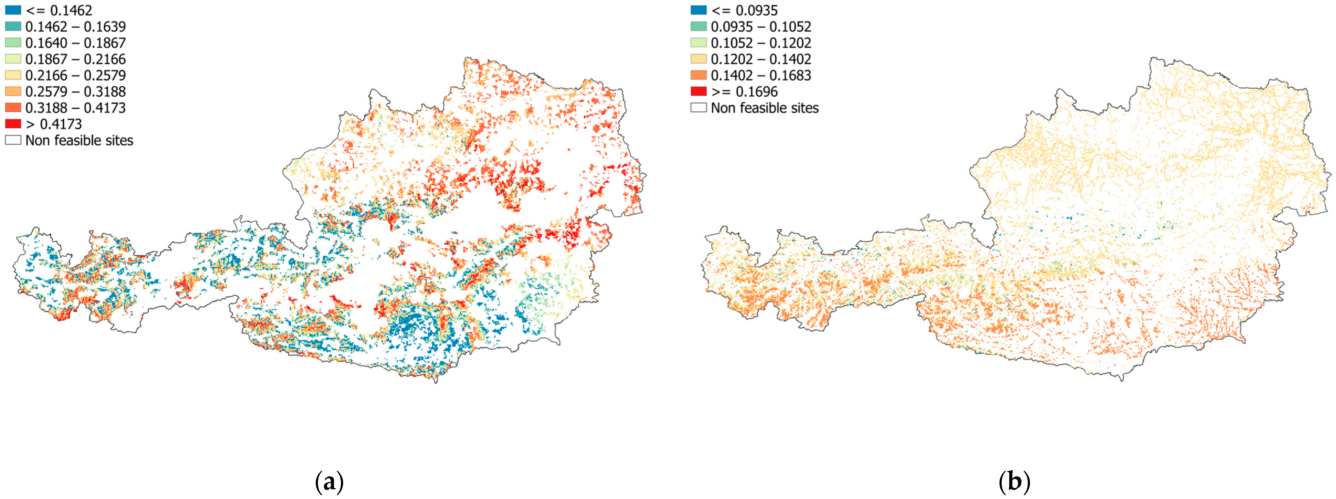
The spatial distribution of Cf-WP and the Cf-PV are shown in Figure 7. The results are, respectively, illustrated as:
  • White: non-feasible sites according to applied criteria
  • Colored (blue to red): lowest to highest Cf-estimates
Even if the maps partly permit the recognition of the main topographic structures, such as mountains, valleys and relatively flat areas, a quite heterogeneous picture of wind resources in Austria emerges. Areas with flatter surroundings benefit from high mean wind speeds. However, the highest Cf-WP according to the conducted analysis can be found in areas with very high elevation in mountainous regions [57]. As the mean wind speed increases with hub height, the availability of high Cf-WP increases [58].
The results of the Cf-analysis show, that the site quality for PV is relatively homogenously distributed throughout Austria. Highly elevated regions show a slightly better Cf due to the reduced impact of the atmosphere [55]. Some areas, especially in valleys, are highly impacted by shadowing due to the elevated surroundings and are therefore not suitable for PV.

3.2. Analysis of the LCOE for WP and PV in Austria

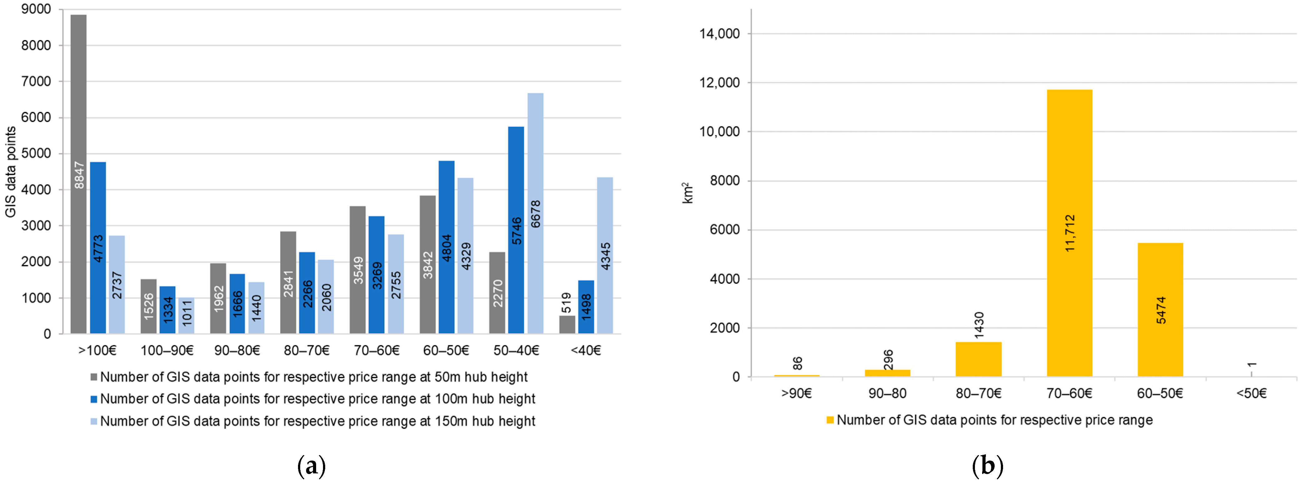
Based on the results of the GIS analysis, steps of the expected values for the REL-Cf are derived for the LCOH model, as listed in Table 10 and Table 11. Further on, each individual REL-Cf is assigned to the respective LCOE range and then the number of values per step is counted, as illustrated in Figure 8. The respective Cf step for each REL-technology is listed in Table 12 and Table 13, respectively.

3.2.1. LCOE for WP in Austria

The highest Cf-WP derived from the GIS analysis is roughly 62.19%, which results in LCOE of 29.35 EUR/MWh. However, this value represents an exception if compared to the average national Cf-WP of 25.5% [59].
The Cf step applied in the model for WP represents an LCOE step of 70 EUR/MWh to 40 EUR/MWh. This cost range is consistent with the cost ranges for WP of other studies [44,60]. Additionally, in Ref. [61], similar Cf ranges for WP in Austria are used. In their analysis, the authors assume 22% as an average Cf-value and 39% as the maximum Cf-value.

3.2.2. LCOE for PV in Austria

The highest Cf-PV found in the course of the GIS analysis is roughly 16.96%, which results in LCOE of 49.63 EUR/MWh. This value is close to the upper limit of the selected LCOE range used for the LCOH model. The lower Cf-PV step limit represents the average Cf-PV in Austria, which is roughly 12% [62].
The Cf step used for PV represents an LCOE step of 70 EUR/MWh to 50 EUR/MWh. This cost range is consistent with the cost ranges for PV of other studies [44,60]. Again, the authors of [61] find similar Cf ranges for PV in Austria. In the analysis, 12.66% as an average value and 15.85% as the maximum value are used.

3.3. Analysis of the LCOH

As two LCOH results are compared, the relative cost difference is calculated by dividing the higher LCOH value by the lower LCOH value and subtracting the result by one. Additionally, the relative values are calculated by using the sharp numbers, not the rounded values depicted in this paper. The cheapest system variant results in 3.08 EUR/kg of hydrogen, as opposed to the most expensive system with 13.12 EUR/kg of hydrogen.

3.3.1. Impact of the EGP, the REL-CF and the PEM-FLH on the LCOH

Firstly, the impact of the EGP and the REL-CF are shown and discussed. Figure 9 shows the significance of these two parameters for system variants with the same yearly hydrogen output. At low PEM-FLH (up to 2000 h), system variants with high Cf-WP do not have a PV capacity. Therefore, the change in Cf-PV has no influence on the LCOH. However, at low Cf-WP, the higher Cf-PV compensates some of the cost increase (cost increase of an average of 34.5% for variants with low Cf for both REL-technologies, opposed to a cost increase of an average of 15.2% for system variants with high Cf-PV). For system variants with high PEM-FLH (4000 h to 5000 h), high REL-Cf are even more essential to decrease the LCOH. The gap between the system variant located in Kremsmuenster with highest REL-Cf compared to the system at same location with lowest REL-Cf results in a relative cost increase of 101.13% (absolute values 3.17 EUR/kg of hydrogen and 6.38 EUR/kg of hydrogen, respectively).
The comparison of the four EGPs shows a smaller impact on the LCOH than the REL-Cf. This is especially true for system variants with low PEM-FLH (1000–2000 h). Nevertheless, for system variants with high PEM-FLH (4000–5000 h), the complementation of the wind profiles and the PV profiles of each location does have a relevant influence on the LCOH. Hereby, according to the modelled LCOH, the Neumarkt location holds the least complementary profiles; Kremsmuenster and Zwerndorf, on the other hand, hold the most complimentary. The most expensive system variant with PEM-FLH of 5000 h and lowest REL-Cf located in Neumarkt is modelled with LCOH of 13.12 EUR/kg of hydrogen. The variant with the same technical specifications but located in Kremsmuenster results in 6.38 EUR/kg of hydrogen. This is a relative cost difference of 105.54%.
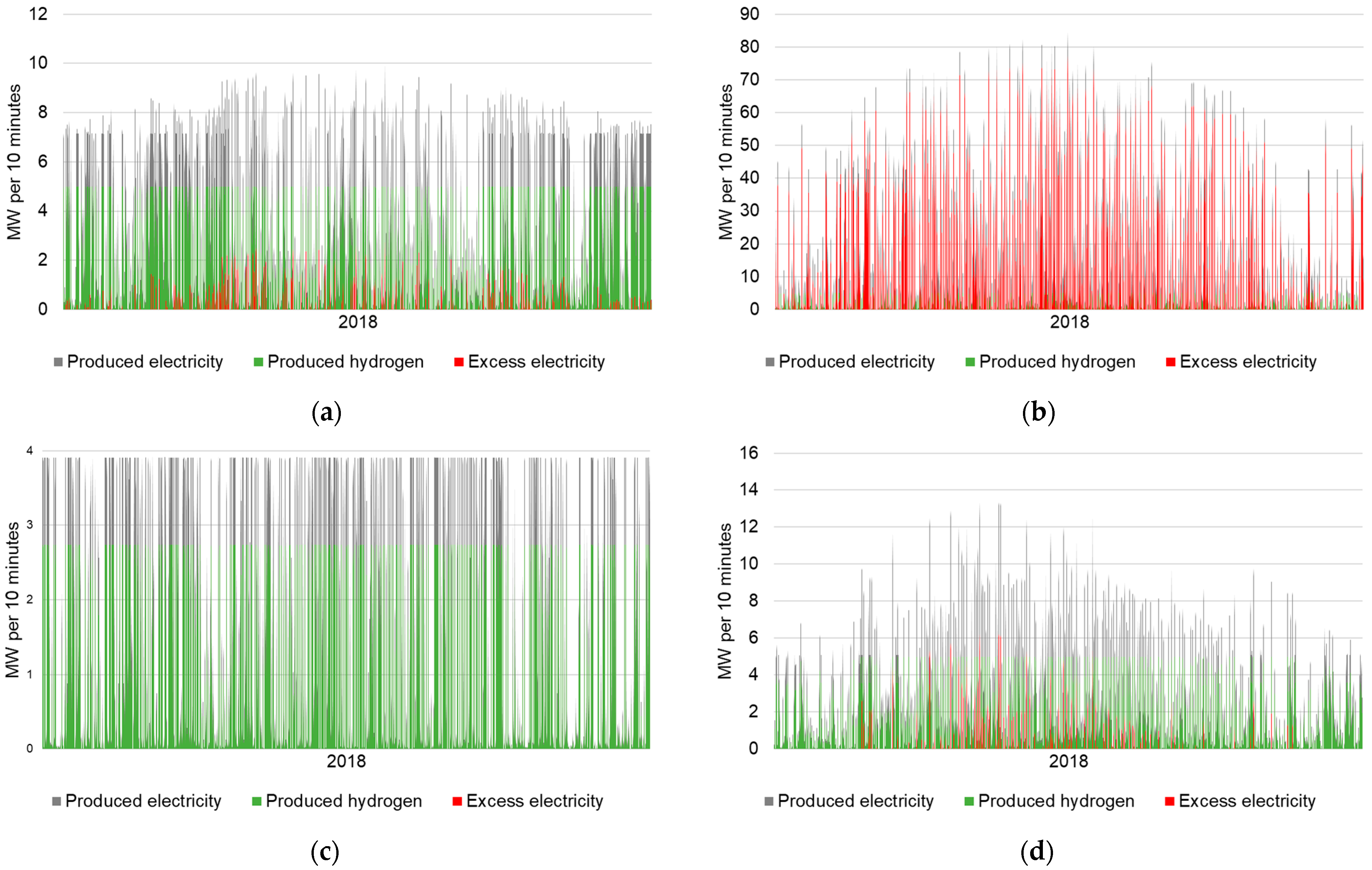
Secondly, the sensitivity of the PEM-FLH is presented. Figure 10a shows the feed-in profile of the cheapest variant modelled. The location is Zwerndorf, the PEM-FLH are set to 4000 h and REL-Cf are for both technologies at the upper step’s limits, with roughly 41.7% for WP and roughly 16.8% for PV, respectively. The installed capacity of WP is roughly 7.1 MW and 2.6 MW for PV. The cost for the produced hydrogen for this variant is 3.08 EUR/kg of hydrogen. The electricity produced in a year for this variant is roughly 29,878 MWh. The share of excess electricity is relatively small, with 4.37% or 1307 MWh in absolute numbers. The LCOH of the variant with the same location and same REL-Cf but with PEM-FLH of 1000 h is modelled with costs at 5.89 EUR/kg of hydrogen. Comparing it to the LCOH of the cheapest variant results in a relative cost increase of 91.38%. This example shows that for economically feasible hydrogen production, it is necessary to adjust the installed capacity of the of the REL-sources with their Cf and the aimed amount of hydrogen produced per year. However, an increase in installed REL-capacity requires space for the realization of REL-projects.
Figure 10b shows the feed-in profile of the most expensive variant modelled. The location is Neumarkt, the PEM-FLH are set to 5000 h and REL-Cf are for both technologies at the lower step’s limits. The installed capacity of WP is roughly 42.7 MW and 50.7 MW for PV. Due to the overbuilding of the electrolyzer’s capacity with RE capacity, the share of excess electricity in the electricity produced is 73.42%. The cost for the produced hydrogen for this variant is 13.12 EUR/kg of hydrogen. The variant with the same REL-Cf and same location but with PEM-FLH of 3000 h is modelled with costs of 5.33 EUR/kg of hydrogen, as for this variant the installed REL-capacity as well as the excess electricity are significantly reduced. The excess electricity to the produced electricity ratio for this variant is 18.21%. The relative cost difference between these two variants is 145.92%.
The next example shows a variant that only connects WP due to the combination of a high WP-Cf (41.7%) and low PEM-FLH (2000 h). Figure 10c shows its electricity feed-in profile. The location for this system is Galtuer. The installed capacity for WP is modelled at roughly 3.9 MW and 0 MW for PV. As the installed REL-capacity falls below the capacity of the PEM electrolyzer, this system produces no excess electricity. The cost for the produced hydrogen for this variant is 3.92 EUR/kg of hydrogen. The variant with the same specifications but PEM-FLH of 3000 h produces hydrogen at the cost of 3.27 EUR/kg of hydrogen, which results in a relative cost difference of 20.01%. The installed capacity for WP is for this system 5.9 MW, and for PV once again 0 MW. This example shows, along with the previous examples, that the LCOH can be reduced by adjusting the installed capacity of the REL-sources with the PEM-FLH.
The final example is a system where the REL-capacity is dominated by PV. Figure 10d shows the feed-in profile of a system variant with installed WP capacity of 5.1 MW and 8.9 MW for PV. The Cf-WP is at the lower step limit and for PV at the higher step limit, respectively. This results in produced electricity of 22,855 MWh, whereas a ratio of 8.96% is excess electricity, which is 1427 MWh in absolute numbers. The excess electricity occurs mainly in the summer months. This variant produces hydrogen at the cost of 4.26 EUR/kg of hydrogen. The variant with the same location and same REL-Cf but with 2000 PEM-FLH results only in a minor cost increase of roughly 5.83% at an LCOH of 4.51 EUR/kg of hydrogen. This system has only minor WP capacity with 0.7 MW and 9.3 MW for PV. It shows that, in locations with good conditions for PV, a REL-portfolio that is PV-dominant is considerable.
Among all locations and REL-Cf, systems with 3000 h or 4000 are the cheapest; in particular, those with high Cf-WP show the lowest costs. This is partly due to the relatively high upper step limit of the WP-Cf. Additionally, WP tends to lead to less excess energy compared to PV, with the same amount of energy produced.
A comparison of the results of the current study to the LCOH estimates listed in Chapter 1.4 shows that, depending on the assumptions, the results are coherent or significantly different. The first quartile and the third quartile of the researched LCOH values range from 5 EUR/kg of hydrogen to 11.04 EUR/kg of hydrogen. A total of 33 of the variants modelled from the current study result within this range. However, system variants with low REL-Cf and low or high PEM-FLH result in relatively high LCOH estimates in the current study. Two variants of the current study result in LCOH higher than 11.04 EUR/kg of hydrogen. However, 45 modelled variants show a cost for hydrogen below 5 EUR/kg. These are systems where all three variable parameters mentioned above are well balanced and the systems benefit from high REL-Cf. However, all modelled results of the current study fall within the full range of results from previous studies (1.8 EUR/kg of hydrogen to 57.61 EUR/kg of hydrogen).
A further detailed comparison to Ref. [32] explains some of the differences in LCOH estimates. In Ref. [32], Tang et al. follow a similar approach to the current study in calculating the LCOH. Four locations are chosen, with respective capacity factors for PV and WP and based on the EGP, the Cf of the electrolyzer is modelled. However, the results show higher values for the LCOH than this paper, ranging from 7 EUR/kg of hydrogen to roughly 15 EUR/kg of hydrogen. The difference in LCOH values can be attributed to the higher CAPEX of WP systems, the higher discount factor, the lower efficiency rate for the electrolyzer of roughly 68.16% (based on the assumption that the electrolyzer requires 48.9 kWh/kg hydrogen and that hydrogen contains 33.33 kWh/kg) as well as the fact that the compared study includes the cost for the hydrogen storage after its production in its analysis. Additionally, Cf-PV as well as Cf-WP are considerably below the upper range of this study for most locations.
In Ref. [33], Bhandari and Shah analyze various hydrogen production system designs for its LCOH. To make a comparison with the current study, the off-grid system with a PEM electrolyzer and an installed battery as one of the system variants of the study is considered. Hereby, the authors find that a battery connection increases the cost of the LCOH significantly, as found by another study [63]. Furthermore, the system design differs greatly from the design of the current study. The Cf of the electrolyzer is set to 100% and WP is not considered in the REL-portfolio. Besides the system design, differing economic input parameters compared to the present study cause parts of the difference in LCOH. Stack replacement is considered to be necessary every five years, with 42% of initial CAPEX for the electrolyzer compared to 35% in this study. Furthermore, the electrolyzer efficiency is assumed to be roughly 48.39% (based on the study’s assumption that the electrolyzer requires 6.2 kWh/Nm3 of hydrogen and that one Nm3 of hydrogen contains 3 kWh/kg).
In Ref. [4], Lundblad et al. investigate off-grid as well as grid-connected hydrogen production systems in a current and future scenario. The off-grid system is designed analogously to the design of the current study. However, it includes a storage tank. Comparing the LCOH of Ref. [4] to the current study, the price estimated for the off-grid system in southern Sweden with an LCOH of roughly 6.7 EUR/kg of hydrogen is more than double the cheapest variant in the current study. Roughly half of the price difference is explained as storage costs are included. Furthermore, the authors assume a less efficient electrolyzer (65%). CAPEX and OPEX for the system components in Ref. [4] are considerably lower than in the present study. However, the production system is modelled to meet a predefined demand of a hydrogen refueling station, which influences the sizing of system components. Further cost differences might be explained by differing assumptions for the REL-Cf. However, the authors do not state the REL-Cf assumed.
In Ref. [34], Janssen et al. calculate the LCOH in an off-grid system that couples REL-sources directly to the electrolyzer for 30 European countries for 2020 with an outlook until 2050. Compared to the current study, the findings in Ref. [34] for Austria in 2020 with roughly 3.01 EUR/kg of hydrogen are almost identical to the cheapest system variant modelled in the current study. The CAPEX of all system components is assumed to be significantly lower than in the present study. In addition, the system lifetime is assumed to be five years longer and the electrolyzer efficiency five percentage points higher. However, the REL-Cf assumed in Ref. [34], with 28% for WP and 13.04% for PV, are significantly lower than the upper threshold of the current study. Additionally, the authors apply a different approach in setting the installed capacity of the system components, as the electrolyzer’s capacity equals that of the peak output capacity of either WP or PV. Additionally, the REL-capacities are set equally, as feed-in profiles are not considered.

3.3.2. Sensitivities of the Economic Input Parameters

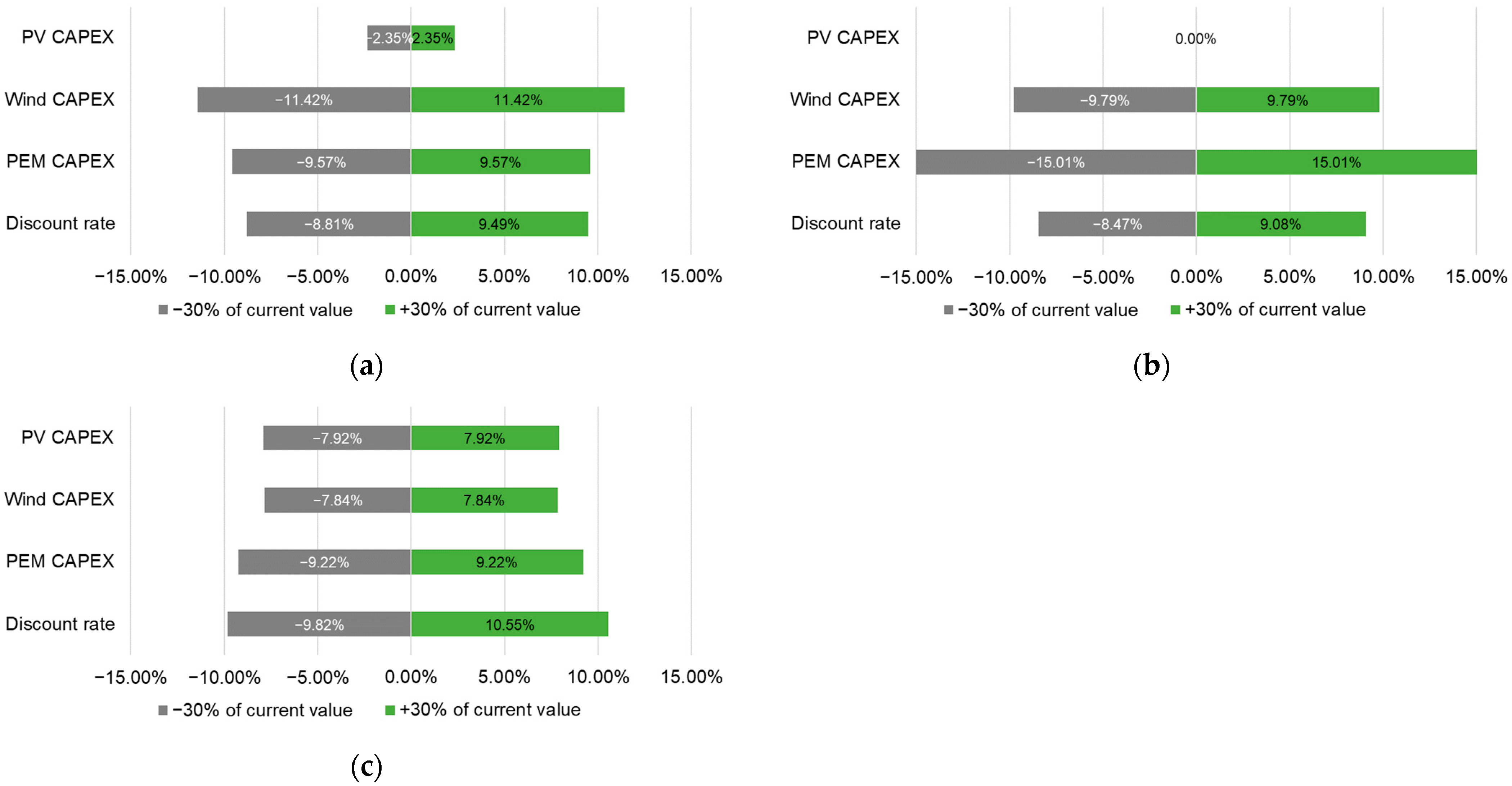
In this chapter, a sensitivity analysis for some selected economic input parameters is conducted. The four parameters are listed in Table 14. As part of the sensitivity analysis, each one of these parameters is reduced by 30% or increased by 30%, respectively.
Figure 11a illustrates the sensitivities of the selected economic input parameters for the cheapest variant. Particular potential hereby is in the reduction of the CAPEX for WP. Additionally, the discount rate as well as the CAPEX for the PEM electrolyzer hold potential for cost reduction. For this variant, the potential cost reduction through a reduction in CAPEX for PV is relatively low, as this variant holds little PV capacity. Figure 11b shows the impact of the selected economic input parameters on the LCOH for a system variant with high capacities in WP compared to its PV capacities. As the system variant has no PV capacities at all, a change in CAPEX in PV has no influence on the LCOH. Again, CAPEX of the PEM electrolyzer, CAPEX of WP as well as the discount rate hold significant potential for cost reduction. Figure 11c, as opposed to the previous figure, exemplifies the change in LCOH for a system variant with high capacities in PV compared to its WP capacities. However, both REL-technologies hold significant potential of reducing the cost of hydrogen for this variant. This shows that, as WP is more cost-intensive than PV, a change in CAPEX of WP has a relatively higher impact on the LCOH even though the installed capacities of WP are relatively low. However, similarly to the previous examples, all other economic input parameters hold a significant potential for the reduction of the LCOH. Comparing the results of the sensitivity analysis of the current study to the results of Ref. [26] shows that both studies depict great potential for cost reduction as well as great uncertainties for future investments. Depending on the system design, some parameters have a great impact, while others may have little influence. Hence, for future project development, it is vital to consider the individual circumstances and to conduct a thorough analysis to achieve an optimal system design.

4. Conclusions

This study investigates the opportunity to produce renewable hydrogen with electricity from WP and PV in Austria and represents a theoretical assessment of a decentralized hydrogen production system with directly coupled REL-sources. The LCOH model applied can be used anywhere in the world by changing the relevant input parameters. With weather data that has a 10-min granularity, the Cf of a PEM electrolyzer is modelled and hence the respective LCOH is estimated. Given the applied methodology and assumptions, the proposed system produces hydrogen at a minimum cost of 3.08 EUR/kg of hydrogen, whereas the maximum cost is estimated to be 13.12 EUR/kg of hydrogen. Feasible LCOE values range from 40 to 70 EUR/MWh and from 50 to 70 EUR/MWh for WP and PV, respectively. Hence, it can be concluded that Austria holds potential for domestic techno-economical-feasible hydrogen production in decentralized production systems. In the future, there are further opportunities for cost reduction, through economies of scale and learning effects of the system components. However, the use of different sensitivities demonstrates that the LCOH is subject to great uncertainties and spotlights the necessity of taking the individual circumstances of technologies, system design and environmental conditions into account. The analysis shows that the LCOH is most dependent on the REL-Cf of the connected electricity production systems as well as the predefined hydrogen output of the production plant. Additionally, with increasing PEM-FLH, the complementation of the EGP has a growing impact on the LCOH. Furthermore, depending on the system variant’s sizing of the system components, a reduction of CAPEX holds significant potential for lowering the LCOH. Therefore, as demonstrated, developers need to balance the REL-portfolio, with the aimed hydrogen output of the electrolyzer and the environmental conditions found in the chosen site.
The following conclusions are relevant for future investors and project developers. The results of the current study show that systems with high WP capacities and high Cf-WP have the lowest LCOH, even at relatively high hydrogen output. However, the lowest LCOH is modelled with a system that well complements the capacities and the feed-in profiles of both REL-technologies. Nevertheless, systems with low hydrogen output are feasible with PV only. Using the results of the current study, project developers have to take additional hydrogen storage and transportation costs into account, as this study does exclude these costs. Choosing a site of production that is close to the site of consumption can minimize these costs. The conducted GIS analysis of the current study gives guidance as to where sites with high REL-Cf can be expected in Austria.
Hydrogen production can be used for many applications. However, the Austrian government sets the focus on decarbonizing energy-intensive industries and on substituting fossil hydrogen as a chemical compound by 2030. Therefore, a policy framework that incentivizes this target group to invest in renewable electricity and hydrogen production plants ought to be part of the political agenda. Such policies can be incentive-based, such as an improvement and a deregulation of the REL-project realization. Furthermore, an increasing CO2 price would incentivize companies as well to foster the decarbonization of their processes. Policies that encourage the realization of renewable hydrogen in Austria can lay the basis for a hydrogen economy within the country. This holds great potential in lowering CO2 emissions as well as benefits for the overall economy.

5. Need for Future Studies

Regarding future research, it will be interesting to integrate other renewable sources of electricity into the REL-portfolio of the hydrogen production system, such as geothermal energy or hydropower, as these technologies are characterized by a less volatile generation profile if compared to WP or PV. In particular, hydropower is interesting when looking at the available resources in Austria. Furthermore, the inclusion of an electrical battery to balance the excess electricity is of interest for future studies as well as modelling the system with different installed capacities and types of electrolyzer. It is also crucial to investigate what intermittency of the fed-in electricity does to an electrolyzer. Finally, future studies should investigate the hydrogen market and estimate opportunity costs. The results of this and other studies should be compared to the alternative decarbonization routes for public and private institutions.

Author Contributions

Conceptualization, R.B. and L.P.; methodology, L.P and R.B.; software, L.P.; data curation, L.P.; writing—original draft preparation, L.P.; writing—review and editing, R.B.; supervision, R.B.; funding acquisition, R.B. All authors have read and agreed to the published version of the manuscript.

Funding

This research was funded by the German Federal Ministry of Education and Research (BMBF) through its Project Management Agency Jülich (PtJ) under the framework of the RETO-DOSSO Project with grant No 03SF0598A. The APC was funded by the same.

Institutional Review Board Statement

Not applicable.

Informed Consent Statement

Not applicable.

Data Availability Statement

The data presented in this study are available on request from the corresponding author. The data are not publicly available due to resource limitations.

Conflicts of Interest

The authors declare no conflict of interest.

Abbreviations

Cfcapacity factor
Cf-PVcapacity factor of solar photovoltaics
Cf-WPcapacity factor of wind power
EAGRenewable Energy Expansion Act of Austria
ECEuropean Commission
EGPelectricity generation profile
EUEuropean Union
GISgeographic information system
LCOElevelized cost of electricity
LCOHlevelized cost of hydrogen
PEMproton exchange membrane
PEM-FLHfull load hours of the proton exchange membrane electrolyzer
PVsolar photovoltaics
RELrenewable electricity
REL-Cfcapacity factors of the renewable electricity sources
WPwind power

References

  1. Bundesministerium für Klimaschutz, Umwelt, Energie, Mobilität, Innovation und Technologie. Wasserstoffstrategie für Österreich; Bundesministerium für Klimaschutz, Umwelt, Energie, Mobilität, Innovation und Technologie: Vienna, Austria, 2022; p. 60. [Google Scholar]
  2. European Commission. A Hydrogen Strategy for a Climate-Neutral Europe; European Commission: Brussels, Belgium, 2020.
  3. Baumann, M.; Fazeni-Fraisl, K.; Kienberger, T.; Nagovnak, P.; Pauritsch, G.; Rosenfeld, D.; Sejkora, C.; Tichler, R. Erneuerbares Gas in Österreich 2040; Bundesministerium für Klimaschutz, Umwelt, Energie, Mobilität, Innovation und Technologie: Vienna, Austria, 2021; p. 94. [Google Scholar]
  4. Lundblad, T.; Taljegard, M.; Johnsson, F. Centralized and decentralized electrolysis-based hydrogen supply systems for road transportation—A modeling study of current and future costs. Int. J. Hydrog. Energy 2023, 48, 4830–4844. [Google Scholar] [CrossRef]
  5. Hydrogen Council. Path to Hydrogen Competitiveness—A Cost Perspective; Hydrogen Council: Brussels, Belgium, 2020; p. 88. [Google Scholar]
  6. Bundesministerium für Wirtschaft und Energie (BMWi). Die Nationale Wasserstoffstrategie; Bundesministerium für Wirtschaft und Energie (BMWi): Berlin, Germany, 2020.
  7. Ministère de la Transition écologique. Stratégie Nationale Pour le Développement de l’hydrogène Décarboné en France; Ministère de la Transition écologique: Paris, France, 2020.
  8. Government of the Netherlands. Government Strategy on Hydrogen; Government of the Netherlands: Amsterdam, The Netherlands, 2020.
  9. Ministero dello sviluppo economico. Strategia Nazionale Idrogeno Linee Guida Preliminari; Ministero dello sviluppo economico: Rome, Italy, 2020. [Google Scholar]
  10. European Commission. Communication from the Commission to the European Parliament, the European Council, the Council, the European Economic and Social Committee and the Committee of the Regions—A Green Deal Industrial Plan for the Net-Zero Age; European Commission: Brussels, Belgium, 2023. [Google Scholar]
  11. Weltenergierat. International Hydrogen Strategies. Available online: https://www.weltenergierat.de/publikationen/studien/international-hydrogen-strategies/ (accessed on 7 September 2022).
  12. Ewa, M. Polish Hydrogen Strategy until 2030 with a Perspective until 2040—Project. 2021. Available online: https://www.gov.pl/web/klimat/rozpoczely-sie-konsultacje-publiczne-projektu-polskiej-strategiiwodorowej (accessed on 15 February 2021).
  13. Gawlik, L.; Mokrzycki, E. Analysis of the Polish Hydrogen Strategy in the Context of the EU’s Strategic Documents on Hydrogen. Energies 2021, 14, 6382. [Google Scholar] [CrossRef]
  14. Westphal, K.; Dröge, S.; Geden, O.; Stiftung Wissenschaft Und Politik. The International Dimensions of Germany’s Hydrogen Policy. SWP Comment. 2020. Available online: https://www.swp-berlin.org/10.18449/2020C32/ (accessed on 20 March 2022).
  15. Department for Business, Energy & Industrial Strategy. UK Hydrogen Strategy; Dandy Booksellers Ltd.: London, UK, 2021; ISBN 978-1-5286-2670-5. [Google Scholar]
  16. Pastore, L.M.; Lo Basso, G.; Sforzini, M.; de Santoli, L. Technical, economic and environmental issues related to electrolysers capacity targets according to the Italian Hydrogen Strategy: A critical analysis. Renew. Sustain. Energy Rev. 2022, 166, 112685. [Google Scholar] [CrossRef]
  17. Department of the Environment, Climate and Communications. Consultation on Developing a Hydrogen Strategy for Ireland; Department of the Environment, Climate and Communications: Cavan, UK, 2022.
  18. De Tommasi, L.; Lyons, P. Towards the Integration of Flexible Green Hydrogen Demand and Production in Ireland: Opportunities, Barriers, and Recommendations. Energies 2022, 16, 352. [Google Scholar] [CrossRef]
  19. van Rossum, R.; Jens, J.; La Guardia, G.; Wang, A.; Kühnen, L.; Overgaag, M. European Hydrogen Backbone—A European Hydrogen Infrastructure Vision Covering 28 Countries. Tech. Rep. 2022. Available online: https://gasforclimate2050.eu/wp-content/uploads/2022/04/EHB-A-European-hydrogen-infrastructure-vision-covering-28-countries.pdf (accessed on 20 March 2022).
  20. Hebling, C.; Ragwitz, M.; Fleiter, T.; Groos, U.; Härle, D.; Held, A.; Jahn, M.; Müller, N.; Pfeifer, T.; Plötz, P.; et al. Eine Wasserstoff-Roadmap für Deutschland; Fraunhofer-Institut für System-und Innovationsforschung ISI: Karlsruhe, Germany, 2019; p. 51. [Google Scholar]
  21. Frontier Economics. Grundlage für die Positionierung zu Wasserstoff—Bericht für OesterreichsEnergie; OesterreichsEnergie: Wien, Vienna, 2021. [Google Scholar]
  22. European Commission. Production of Renewable Transport Fuels—Share of Renewable Electricity (Requirements); European Commission: Brussels, Belgium, 2022. [Google Scholar]
  23. Bundesgesetz über den Ausbau von Energie aus Erneuerbaren Quellen (Erneuerbaren-Ausbau-Gesetz—EAG). 2022. Available online: https://www.ris.bka.gv.at/GeltendeFassung.wxe?Abfrage=Bundesnormen&Gesetzesnummer=20011619 (accessed on 4 September 2022).
  24. Fuchs, M. Wasserkraftpotenzialstudie Österreich Aktualisierung 2018; Pöyry: Helsinki, Finland, 2018. [Google Scholar]
  25. Tremel, A. Electricity-Based Fuels; SpringerBriefs in Applied Sciences and Technology; Springer International Publishing: Cham, Switzerland, 2018; ISBN 978-3-319-72458-4. [Google Scholar]
  26. Department for Business, Energy & Industrial Strategy. Hydrogen Production Costs 2021; GOV.UK: London, UK, 2021; p. 36.
  27. Zhou, Y.; Searle, S. Cost of Renewable Hydrogen Produced Onsite at Hydrogen Refueling Stations in Europe. 2022. Available online: https://theicct.org/wp-content/uploads/2022/02/fuels-eu-cost-renew-H-produced-onsite-H-refueling-stations-europe-feb22.pdf (accessed on 1 September 2022).
  28. Prognos; Öko-Institut; Wuppertal Institut. Klimaneutrales Deutschland 2045—Wie Deutschland seine Klimaziele schon vor 2050 erreichen kann—Langfassung im Auftrag von Stiftung Klimaneutralität, Agora Energiewende und Agora Verkehrswende. p. 120. Available online: https://www.agora-verkehrswende.de/veroeffentlichungen/klimaneutrales-deutschland-2045-langfassung/#:~:text=Ein%20klimaneutral-es%20Deutschland%20ist%20bereits,Leitmarkt%20und%20Leitanbieter%20f%C3%BCr%20Klimaschutztechnologien (accessed on 2 September 2022).
  29. Prognos, A.G. Kosten und Transformationspfade für strombasierte Energieträger; Bundesministeriums für Wirtschaft und Energie: Berlin, Germany, 2020; p. 107. [Google Scholar]
  30. IEA. The Future of Hydrogen—Seizing Today’s Opportunities. Rep. Prep. Int. Energy Agency G20 Jpn. 2019. Available online: https://www.iea.org/reports/the-future-of-hydrogen (accessed on 22 August 2022).
  31. Schoehuijs, T. Direct Coupling Feasibility Evaluation—Predicting the Price of Hydrogen Produced by Solar Energy; Delft University of Technology: Delft, The Netherlands, 2018. [Google Scholar]
  32. Tang, O.; Rehme, J.; Cerin, P. Levelized cost of hydrogen for refueling stations with solar PV and wind in Sweden: On-grid or off-grid? Energy 2022, 241, 122906. [Google Scholar] [CrossRef]
  33. Bhandari, R.; Shah, R.R. Hydrogen as energy carrier: Techno-economic assessment of decentralized hydrogen production in Germany. Renew. Energy 2021, 177, 915–931. [Google Scholar] [CrossRef]
  34. Janssen, J.L.L.C.C.; Weeda, M.; Detz, R.J.; van der Zwaan, B. Country-specific cost projections for renewable hydrogen production through off-grid electricity systems. Appl. Energy 2022, 309, 118398. [Google Scholar] [CrossRef]
  35. Bundesministerium für Finanzen. Digitales Geländemodell (DGM) Österreich. Available online: https://www.data.gv.at/katalog/dataset/dgm (accessed on 13 March 2022).
  36. European Environment Agency. Copernicus Land Monitoring Service—EU-DEM—European Environment Agency. Available online: https://www.eea.europa.eu/data-and-maps/data/copernicus-land-monitoring-service-eu-dem (accessed on 13 March 2022).
  37. Geofabrik GMBh. OpenStreetMap Data for Austria. Available online: https://download.geofabrik.de/europe/austria.html (accessed on 13 March 2022).
  38. Copernicus. CORINE Land Cover—Copernicus Land Monitoring Service. Available online: https://land.copernicus.eu/pan-european/corine-land-cover (accessed on 10 August 2022).
  39. Technical University of Denmark (DTU). Global Wind Atlas 3.0, a Free, Web-Based Application Developed, Owned and Operated by the Technical University of Denmark (DTU). The Global Wind Atlas 3.0 Is Released in Partnership with the World Bank Group, Utilizing Data Provided by Vortex, Using Funding Provided by the Energy Sector Management Assistance Program (ESMAP). Available online: https://globalwindatlas.info (accessed on 3 August 2021).
  40. Global Solar Atlas. Available online: https://globalsolaratlas.info (accessed on 20 March 2022).
  41. Copernicus. CLC 2018—Copernicus Land Monitoring Service. Available online: https://land.copernicus.eu/pan-european/corine-land-cover/clc2018 (accessed on 13 March 2022).
  42. European Environment Agency. Natura 2000 End 2020—Shapefile—European Environment Agency. Available online: https://www.eea.europa.eu/data-and-maps/data/natura-12/natura-2000-spatial-data/natura-2000-shapefile-1 (accessed on 13 March 2022).
  43. European Environment Agency. Nationally Designated Areas (CDDA)—European Environment Agency. Available online: https://www.eea.europa.eu/data-and-maps/data/nationally-designated-areas-national-cdda-16 (accessed on 13 March 2022).
  44. Kost, C.; Shammugam, S.; Fluri, V.; Peper, D.; Memar, A.D.; Schlegl, T. Stromgestehungskosten Erneuerbare Energien; Fraunhofer-Institute for Solar Energy Systems ISE: Freiburg, Germany, 2021; p. 49. [Google Scholar]
  45. Cost of Capital Study 2021—Sustainability vs. Return ESG as a Key Driver for Long-Term Performance? KPMG AG Wirtschaftsprüfungsgesellschaft: Amstelveen, The Netherlands, 2021; p. 56.
  46. IRENA. Renewable Power Generation Costs in 2020; International Renewable Energy Agency: Abu Dhabi, United Arab Emirates, 2021; p. 180. [Google Scholar]
  47. Chan, A.; Hart, D.; Lehner, F.; Madden, B.; Standen, E.; Bertuccioli, L. Development of Water Electrolysis in the European Union. 2014. Available online: https://www.h2knowledgecentre.com/content/researchpaper1120 (accessed on 13 July 2022).
  48. Glenk, G.; Reichelstein, S. Economics of converting renewable power to hydrogen. Nat. Energy 2019, 4, 216–222. [Google Scholar] [CrossRef] [Green Version]
  49. Smolinka, T.; Aschbrenner, S.; Marius, H.; Voglstätter, C.; Grimm, G. Cost Forecast for Low-Temperature Electrolysis—Technology Driven Bottom-Up Prognosis for PEM and Alkaline Water Electrolysis Systems. 2021. Available online: https://www.ise.fraunhofer.de/content/dam/ise/de/documents/publications/studies/cost-forecast-for-low-temperature-electrolysis.pdf (accessed on 28 June 2022).
  50. Bareiß, K.; de la Rua, C.; Möckl, M.; Hamacher, T. Life cycle assessment of hydrogen from proton exchange membrane water electrolysis in future energy systems. Appl. Energy 2019, 237, 862–872. [Google Scholar] [CrossRef]
  51. Zentralanstalt für Meteorologie und Geodynamik (ZAMG). ZAMG Data Hub. Available online: https://data.hub.zamg.ac.at/ (accessed on 21 July 2022).
  52. IG Windkraft—Austrian Wind Energy Association. Windfakten—Abstandsregelung. Available online: https://windfakten.at/?xmlval_ID_KEY[0]=1240 (accessed on 13 March 2022).
  53. ENERCON GmbH. ENERCON Product Overview. 2015. Available online: https://www.wind-turbine-models.com/turbines/832-enercon-e-115-3.000 (accessed on 13 March 2022).
  54. International Electrotechnical Commission. IEC 61400-12-1:2017—Wind Energy Generation Systems—Part 12-1: Power Performance Measurements of Electricity Producing Wind Turbines; International Electrotechnical Commission: Geneva, Switzerland, 2017. [Google Scholar]
  55. Fechner, H. Ermittlung des Flächenpotentials für den Photovoltaik-Ausbau in Österreich: Welche Flächenkategorien sind für die Erschließung von besonderer Bedeutung, um das Ökostromziel realisieren zu können. ÖsterreichsEnergie. 2020. Available online: https://oesterreichsenergie.at/fileadmin/user_upload/Oesterreichs_Energie/Publikationsdatenbank/Studien/2020/PV-Studie_2020.pdf (accessed on 20 March 2022).
  56. Konstantin, P. Praxisbuch Energiewirtschaft; Springer: Berlin/Heidelberg, Gernamy, 2017; ISBN 978-3-662-49822-4. [Google Scholar]
  57. Hau, E.; von Renouard, H. (Eds.) The Wind Resource. In Wind Turbines: Fundamentals, Technologies, Application, Economics; Springer: Berlin/Heidelberg, Gernamy, 2006; pp. 451–483. ISBN 978-3-540-29284-5. [Google Scholar]
  58. Hau, E.; von Renouard, H. (Eds.) Power Output and Energy Yield. In Wind Turbines: Fundamentals, Technologies, Application, Economics; Springer: Berlin/Heidelberg, Gernamy, 2006; pp. 485–532. ISBN 978-3-540-29284-5. [Google Scholar]
  59. Fuernsinn, B.; Wonisch, P.; Krenn, A. IEA Wind TCP 2020 Annual Report. 2022. Available online: https://www.seai.ie/publications/IEA_Wind_Annual_Report_2020.pdf (accessed on 30 August 2022).
  60. Sens, L.; Neuling, U.; Kaltschmitt, M. Capital expenditure and levelized cost of electricity of photovoltaic plants and wind turbines—Development by 2050. Renew. Energy 2022, 185, 525–537. [Google Scholar] [CrossRef]
  61. Fuel Cells and Hydrogen Observatory Levelised Cost of Hydrogen|FCHObservatory. Available online: https://www.fchobservatory.eu/observatory/technology-and-market/levelised-cost-of-hydrogen-green-hydrogen-costs (accessed on 1 September 2022).
  62. AIT Austrian Institute of Technology GmbH. Gutachten—Referenzkosten Photovoltaik—Gemäß Verordnung EU Nr. 651/2014; OeMAG Abwicklungsstelle für Ökostrom AG: Vienna, Austria, 2021; p. 12. [Google Scholar]
  63. Hinkley, J.; Hayward, J.; McNaughton, R.; Gillespie, R.; Matsumoto, A.; Watt, M.; Lovegrove, K. Cost Assessment of Hydrogen Production from PV and Electrolysis; CSIRO: Canberra, Australia, 2016; p. 44. [Google Scholar]
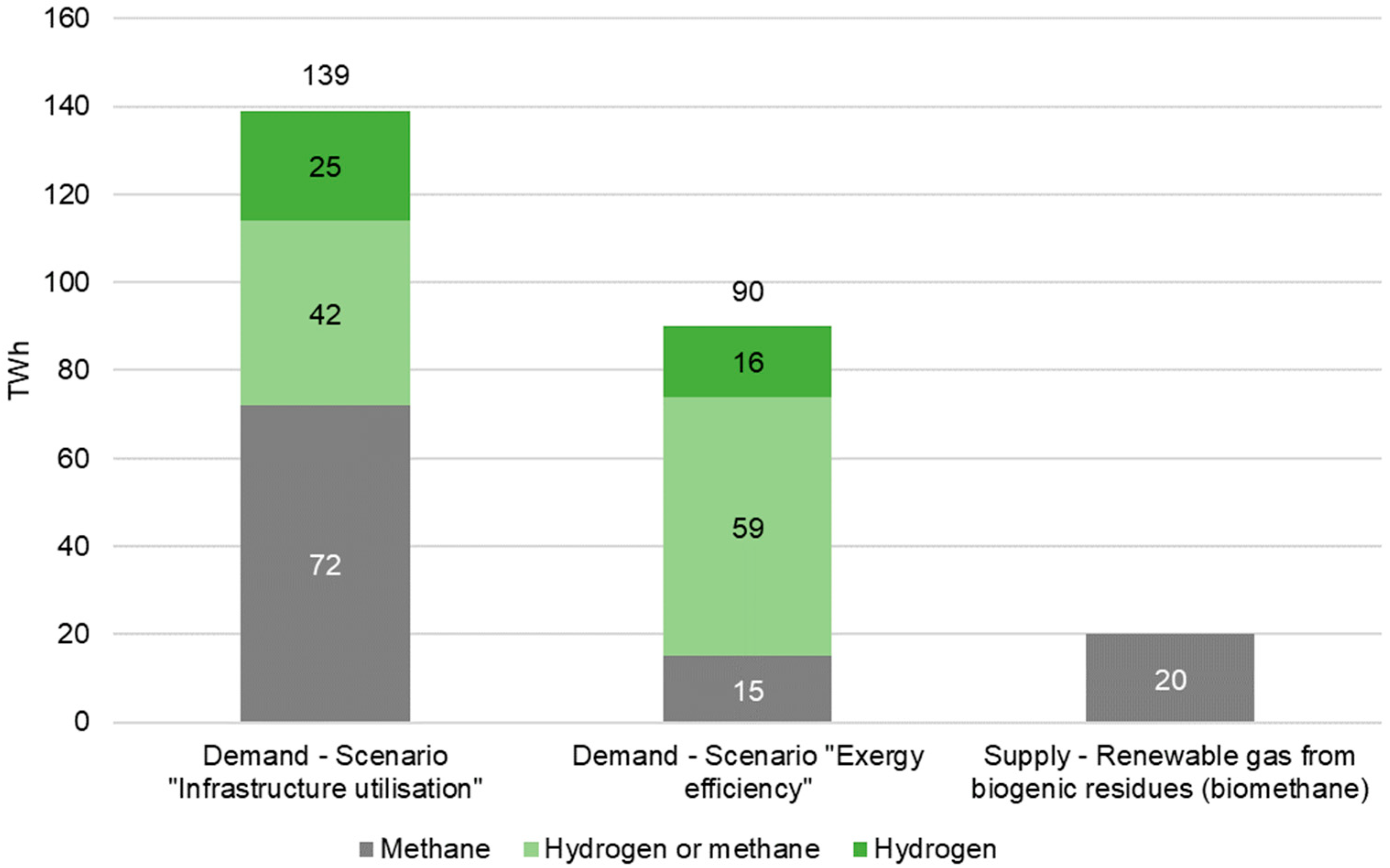
Figure 1. Gas demand in Austria in 2040.
Sustainability 15 04575 g001
Figure 2. Plant design, including REL-plants, electrolyzer and hydrogen output at nozzle.
Sustainability 15 04575 g002
Figure 3. Scheme of the conducted analysis.
Sustainability 15 04575 g003
Figure 4. Climate data for the Zwerndorf location: (a) Wind speed distribution; (b) Global radiation distribution.
Sustainability 15 04575 g004
Figure 5. Comparison of the 10-min frequency distribution: (a) Wind speed at all four selected locations; (b) Global radiation at all four selected locations.
Sustainability 15 04575 g005
Figure 6. Comparison of the monthly frequency distribution: (a) Wind speed at all four selected locations; (b) Global radiation at all four selected locations.
Sustainability 15 04575 g006
Figure 7. Geographic distribution of the REL-Cf in Austria: (a) Distribution of Cf-WP at 100 m hub height; (b) Distribution of Cf-PV in Austria.
Sustainability 15 04575 g007
Figure 8. Distribution of the results of the GIS-analysis: (a) LCOE ranges for WP at respective hub heights; (b) LCOE ranges for PV.
Sustainability 15 04575 g008
Figure 9. Sensitivity analysis of the variables EGP and REL-Cf (difference to lowest value signaled by color with white to red as low to high): (a) System variants with 1000 PEM-FLH; reference cost for the relative values is 5.89 EUR/kg of hydrogen; (b) System variants with 2000 PEM-FLH; reference cost for the relative values is 3.92 EUR/kg of hydrogen; (c) System variants with 4000 PEM-FLH; reference cost for the relative values is 3.08 EUR/kg of hydrogen; (d) System variants with 5000 PEM-FLH; reference cost for the relative values is 3.17 EUR/kg of hydrogen.
Sustainability 15 04575 g009
Figure 10. Feed-in profiles: (a) Cheapest system variant, located in Zwerndorf with 4000 PEM-FLH, Cf-WP of 41.7% and Cf-PV of 16.8%; (b) Most expensive system variant, located in Neumarkt with 5000 PEM-FLH, Cf-WP of 21.7% and Cf-PV of 12%; (c) System variant with installed capacity of WP only, located in Galtuer with 2000 PEM-FLH, Cf-WP of 41.7% and Cf-PV of 12%; (d) System variant with an REL-portfolio dominated by PV capacities located in Kremsmuenster, with 3000 PEM-FLH, Cf-WP of 21.7% and Cf-PV of 16.8%.
Sustainability 15 04575 g010
Figure 11. Sensitivity analysis of selected economic input parameters: (a) The cheapest system variant located in Zwerndorf with a modelled hydrogen price of 3.08 EUR/kg of hydrogen; (b) WP-dominant system variant located in Galtuer with a modelled hydrogen price of 3.92 EUR/kg of hydrogen; (c) PV-dominant system variant located in Kremsmuenster with a modelled hydrogen price of 4.26 EUR/kg of hydrogen.
Sustainability 15 04575 g011
Table 1. Comparison of previous research in the field of levelized cost of renewable hydrogen.
AuthorSystem Design/
Assumptions
Economic Input ParametersRegion/YearLCOH in EUR/kgSource
UK.GOV BEIS (2021)Lifetime 30 years; electrolyzer capacity 10 MW; off-grid; REL-source wind offshore with Cf of 51% 2025; compression and storage cost excludedCosts for electrolyzer for offshore system not specifiedUK/20255.13[26]
ICCT (2022)Lifetime 60,000 h; electrolyzer capacity 1 MW; grid-connected, Cf-PEM of 95%; 30 bar at nozzle; electrolyzer efficiency 56%Electricity cost country specific; electrolyzer CAPEX 1005 EUR/kW; WACC country specific; electrolyzer efficiency 56%EU average/20205–6[27]
Prognos et al. (2021)Lifetime 25 years; FLH electrolyzer 3500 h; grid-connected; electrolyzer efficiency 72%Electricity cost 62 EUR/MWh; electrolyzer CAPEX 500 EUR/kW; WACC 6%; stack replacement after 12.5 years with costs of 35% of CAPEXGermany/20205[28]
Frontier economics (2021)Lifetime 20 years; off-grid; Cf-W 26.25% and Cf-PV 10.73%; electrolyzer efficiency 70%Electrolyzer CAPEX 700 EUR/kW; electrolyzer OPEX fix 1.5% of CAPEX/year;Austria/20303.57–6.57[21]
Prognos (2019)FLH electrolyzer 5000 h; grid-connected; REL-source WP and PV 54 to 75 EUR/MWh; including transport and storageWACC 10%; 48% of LCOH is electricity, 27% of LCOH is CAPEX, 8% of LCOH is OPEX; minor share of LCOH are water costsGermany/20207[29]
IEA (2019) 1FLH electrolyzer 4000 h; grid-connectedElectricity cost 35.71 EUR/MWhEU average/20301.8–3.6[30]
Schoehuijs (2020)Lifetime 20 years; off-grid; REL-source PV with Cf of 26.26%; storage includedElectrolyzer CAPEX 700 EUR/kW, OPEX fix 4% of initial CAPEX/year; WACC 4%Netherlands/20183.35[31]
Tang et al.
(2022)
Lifetime 20 years; PEM electrolyzer with installed capacity 270 kW; off-grid REL-system with PV and WP each 250 kW directly coupled; Cf-PV 10.51% to 11.24%; Cf-WP 11.57% to 50.71%; hydrogen production is 47,000 kg/year; storage unit with 1900 kg H2 capacity; including storagePEM CAPEX 2518 EUR/kW, OPEX 1% of CAPEX/year; Compressor CAPEX 250,000 EUR; CAPEX PV 700 EUR/kW; CAPEX WP 2000 EUR/kW; Storage unit CAPEX 195,000 EUR; WACC 6%SWE/20207–15.08[32]
Bhandari and Shah (2021)Lifetime 20 years; PEM electrolyzer with capacity of 10 Nm3/h; off-grid PV system with 3.3 MW directly coupled including battery with a size of 9125 kWh; PEM-FLH 8760 h; surplus energy by the PV feeds the batteries; deficit of PV for PEM electrolyzer is supplied by batteryPEM CAPEX 1000 EUR/kW, OPEX 2% of CAPEX/year; stack replacement 420 EUR/kW; stack lifetime 5 years; water cost 3 EUR/m3; PV CAPEX 800 EUR/kWp; PV OPEX 1% of PV CAPEX/yearGermany/202057.61[33]
Lundblad et al.
(2023) 2
Lifetime 25 years; off-grid system directly coupled; FLH of the electrolyzer are set to roughly 4000; hydrogen production and storage modelled to meet demand of a hydrogen refueling station; including storage and/or transportationElectrolyzer efficiency of 65%, CAPEX 900,000 EUR/MW, annual O&M of $% of CAPEX of electrolyzer; CAPEX, annual fixed and variable OPEX of 1,120,000 EUR/MW, 14,000 EUR/MW and 1.5 EUR/MWh for WP; CAPEX and annual fixed O&M of 560,000 EUR/MW and 11,300 EUR/MW for PV; WACC 5%Sweden/20226.7[4]
Janssen et al.
(2022)
Lifetime 30 years; off-grid system directly coupled; electrolyzer capacity equals peak output capacity of either WP or PV; FLH of electrolyzer depend on REL-Cf; installed capacity of WP and PV are equal in hybrid system; Cf-WP 28%; Cf-PV 13.04%Electrolyzer efficiency of 70%, CAPEX 700,000 EUR/MW, OPEX 30,000 EUR/MW; loan depreciation of 10 years; WACC 5%; CAPEX WP 1,040,000 EUR/MW, OPEX 3%; CAPEX PV 690,000 EUR/MW, OPEX 2%Austria/20203.01[34]
1 Assuming an average exchange rate in 2019 of 1.12 USD = 1 EUR; 2 Numbers are taken from current scenario.
Table 2. Data components, data sources and data usage.
Data ComponentData UsageData Source
Topographic dataTopographic data is used in raster as well as shape format. With its use technically feasible, socially accepted sites for WP and PV, respectively, are determined. The spatial resolution is scaled to 1 km2. [35,36,37,38]
Climatic dataClimatic data is used in raster format. It forms the basis for the calculation of the REL-Cf. The spatial resolution is scaled to 1 km2.[39,40]
Political mapsPolitical maps are used in shape format. With its use technically feasible, socially accepted sites for WP and PV, respectively, are determined. The resolution is vectorized.[38,41,42,43]
Economic input dataEconomic input parameters are used to determine the CAPEX as well as variable and fixed OPEX of the hydrogen production system components. The selection followed by a thorough literature research focused on parameters specifically referring to Austria and, if not available, Western Europe.[28,44,45,46,47,48,49,50]
Weather dataThe weather data from real weather stations in Austria forms the basis for the EGP of WP and PV. It has a 10-min granularity. 2018 is chosen as a representative weather year.[51]
Table 3. Criteria for the excluded areas to determine potentially feasible WP sites in Austria.
CategoryDescriptionGIS Data Source
ElevationAreas with a sea level above 2000 m are excluded[35]
SlopeAreas with a slope exceeding 15° are excluded[36]
InfrastructureInfrastructural networks, including roads, railways and the electrical grid, with a buffer of 200 m along the lines are excluded[37]
RiversAreas covered by rivers including a buffer of 200 m are excluded[37]
Settlement areasSettlement areas with a buffer of 1200 m are excluded[41]
Nature conservation areasNature conservation areas, including Natura 2000 and nationally designated areas are excluded[42,43]
Table 4. Selected areas for PV plants in Austria according to categories of the EU land use map.
Category 1 AreasCategory 2 Areas
Industrial or commercial unitsNon-irrigated arable land
Dump sitesPastures
Natural grasslandsLand principally occupied by agriculture, with significant areas of natural vegetation
Table 5. Economic input parameters used to calculate the LCOE of WP.
ParameterValueUnitSource
Nominal investment1,400,000[EUR/MW][44]
Fixed O&M20,000[EUR/MW/a][44]
Variable O&M8[EUR/MWh][44]
Discount rate4.9[%][45]
Table 6. Economic input parameters used to calculate the LCOE of utility scale PV.
ParameterValueUnitSource
Nominal investment804,954[EUR/MW][46]
Fixed O&M13,300[EUR/MW/a][46]
Variable O&M0[EUR/MWh]
Discount rate4.9[%][45]
Degradation rate0.5[%/a][56]
Table 7. Austrian weather station locations used for load profile generation.
Name of Weather StationLongitude [°E]Latitude [°N]Weather Station’s Sea Level [m]Federal State
Zwerndorf16.8348.34144Lower Austria
Kremsmuenster14.1348.06382Upper Austria
Neumarkt14.4247.07869Styria
Galtuer10.1946.971587Tirol
Table 8. Economic input parameter of the 5 MW PEM electrolyzer.
Component2020 [EUR/kW]
Electrolysis stacks294
Power electronics195
BoP Cathode + H2 Purification76
BoP Anode26
H2O Purification9
System Cooling12
Compression0
Piping98
Instrumentation122
Housing19
Engineering128
Sum978
Table 9. Additional economic parameters of the PEM electrolyzer used for the LCOH calculation.
ParameterValueSource
OPEX fix2.2% of initial PEM CAPEX[47]
Costs for water0.09 EUR/kg of H2[48]
Discount rate4.9%[45]
Stack lifetime 18.3 years[50]
Stack replacement cost35% of initial PEM CAPEX[28]
1 Stack lifetime results in two stack replacements during the system lifetime of 25 years. First replacement occurs in the 8th year, second replacement in the 16th year.
Table 10. Cf classes for WP with 10 EUR steps.
Class [EUR/MWh]Cf-WP [%]
>100<14.62
100–9014.62–16.40
90–8016.40–18.67
80–7018.67–21.66
70–6021.66–25.79
60–5025.79–31.88
50–4031.88–41.73
<40>41.73
Table 11. Cf classes for PV with 10 EUR step.
Class [EUR/MWh]Cf-PV [%]
>90<9.35
90–809.35–10.52
80–7010.52–12.03
70–6012.03–14.03
60–5014.03–16.84
<50>16.84
Table 12. Cf-WP step used for the LCOH model.
REL-TechnologyCf—Lower Step LimitCf—Upper Step Limit
WP21.658%41.728%
Table 13. Cf-PV steps used for the LCOH model.
REL-TechnologyCf—Lower Step LimitCf—Upper Step Limit
PV12.025%16.835%
Table 14. Absolute values of the selected parameters for the sensitivity analysis of the economic input parameters.
ParameterLower Step LimitUpper Step LimitUnit
PV CAPEX563,4681,046,440[EUR/MW]
Wind CAPEX980,0001,820,000[EUR/MW]
PEM CAPEX 1684,6001,271,400[EUR/MW]
Discount rate3.436.37[%]
1 Changes in PEM CAPEX change the cost for stack replacement and fixed OPEX (stack replacement cost assumption is 35% of initial PEM CAPEX; fixed OPEX assumption is 2.2% of initial CAPEX).
Disclaimer/Publisher’s Note: The statements, opinions and data contained in all publications are solely those of the individual author(s) and contributor(s) and not of MDPI and/or the editor(s). MDPI and/or the editor(s) disclaim responsibility for any injury to people or property resulting from any ideas, methods, instructions or products referred to in the content.