Article

Alternating Iterative Power-Flow Algorithm for Hybrid AC–DC Power Grids Incorporating LCCs and VSCs

School of Electrical Engineering, Southeast University, Sipailou No. 2, Nanjing 211189, China
*
Author to whom correspondence should be addressed.
Sustainability 2023, 15(5), 4573; https://doi.org/10.3390/su15054573
Submission received: 8 February 2023 / Revised: 23 February 2023 / Accepted: 2 March 2023 / Published: 3 March 2023
(This article belongs to the Section Energy Sustainability)

Abstract

:
AC–DC power-flow calculation is the basis for studying HVDC systems. Since traditional iterative methods need many alternative iterations and have convergence problems, this paper proposes an alternating iterative power-flow algorithm for hybrid AC–DC power grids incorporating line-commutated converters (LCCs) and voltage source converters (VSCs). Firstly, the algorithm incorporates the converter interface model into the AC side, considering the influence of the DC side on the AC side, and establishes an AC-augmented Jacobian matrix model with LCC/VSC interface equation variables. Then, according to the type of converter, control mode, and DC grid control strategy, a DC grid power-flow calculation model under various control modes is established for realizing the power-flow decoupling calculation of AC–DC power grids incorporating LCCs and VSCs. The accuracy and effectiveness of the improved algorithm are evaluated using modified IEEE 57 bus AC–DC networks and the CIGRE B4 DC grid test system. The improved algorithm is applicable to various DC grid control modes and considers the reasonable adjustment of the DC grid variable constraints and operating modes.

1. Introduction

A hybrid AC–DC transmission system consisting of a line-commutated converter (LCC)/voltage source converter (VSC) and AC grid is likely to become an important transmission method in the future [1,2,3]. With the increasing scale of the DC grid, the non-linear discrete control process of the DC grid changes the dynamic characteristics of the AC grid, and the difficulty of operation control increases sharply [4,5]. At the same time, the vulnerability of the DC grid to faults has also changed the scope of fault impact and put forward new requirements for relevant stability and recovery-control technology [6,7]. In addition, power-flow analysis is an important premise and foundation when analyzing the steady and transient operation of AC–DC power grids, while designing the corresponding control modes [8,9,10]. To meet this need, in our paper, by incorporating the converter interface model into the AC side, we propose an alternating iterative power-flow algorithm for hybrid AC–DC power grids incorporating LCCs and VSCs, consider the interaction between the DC side and the AC side, and establish an augmented-exchange Jacobian matrix model with LCC/VSC interface equation variables.
In recent years, extensive research efforts have been carried out on AC–DC power-flow calculation methods to support the increasing scale of DC grids [11,12,13]. Hybrid AC–DC power-flow calculation methods can be divided into two categories: unified solution methods and alternating solution methods [14,15]. Unified solution methods have satisfactory convergence, and the number of iterations is small. However, the program inheritance is poor [16,17]. As the size of the DC grid increases, so does the computational complexity, resulting in a decrease in iteration speed [18]. The alternating iteration method has the advantages of fast calculation speed, strong program inheritance, and convenient control-mode switching [19,20,21]. However, it has high requirements for the initial value of the AC grid and poor convergence. In response to these problems, scholars have conducted research [22,23,24,25,26]. An alternative solution approach is proposed to solve the multi-terminal VSC-HVDC power-flow problem [22,23]. This is a full VSC-HVDC power-flow solution, but the strong convergence characteristics of the Newton–Raphson method are sacrificed due to the sequential iterative solution adopted. Authors of [24] present a new model of VSC-HVDC aimed at power-flow solutions using the Newton–Raphson method. Due to its pure AC–DC grid decomposition, the simplification of elements within the converter stations is not required. In [25], based on typical three- and five-terminal DC grids, the nodal admittance matrix-based Gauss–Seidel method and the nodal impedance matrix-based Gauss–Seidel method were investigated and compared for a DC grid power-flow calculation. Authors of [26] analyzed the reasons for repeated alternating and proposed an AC–DC decoupled hybrid power-flow algorithm for a hybrid power system with VSC.
The open-source program MatACDC is based on VSC-HVDC for a power-flow calculation of an AC–DC hybrid system [27]. This program is based on the Matpower program for AC power-flow calculation and is used to calculate the conventional power flow of the hybrid system. MatACDC uses a sequential AC–DC power-flow routine to solve the network. The traditional sequential methods need many alternative iterations and have convergence problems. In order to overcome the shortcomings of these two types of method, researchers have also achieved some results in this area. In [28], a general alternating iterative AC–DC power-flow method is proposed, which is based on the decoupled equivalence of different control methods of a VSC on the AC and the DC sides. It avoids the repeated alternation process and reduces the total calculation amount by adjusting the control parameter of a VSC and the dividing line between AC and DC subsystems. When the AC side is a radial distribution network, the convergence of the calculation becomes poor when using the forward backpropagation method for the AC-side power-flow calculation; this is the next problem to be investigated and solved by this AC–DC decoupling power-flow algorithm.
Table 1 includes the main features of the literature on AC–DC power-flow calculations. Nevertheless, the latest research still has limitations in two aspects: (1) In traditional alternating iterations, due to the poor coupling between AC and DC, multiple iterations are required to realize the convergence of the power-flow calculation results. With the increasing scale of the DC grid, this problem will be more prominent. (2) VSC and LCC differ significantly in terms of control modes. The two power-flow calculation models and their algorithms are not universal. In AC–DC power-flow calculations with a VSC, the characteristics of the loss of the VSC, various control strategies of the DC grid, and efficient calculation methods under various control modes must be considered. In addition, in the calculation of AC–DC power flow with an LCC, the coupling relationship between the DC state variable and the AC side must be considered. The main aims of this paper are follows: based on the traditional alternating iterative method, this paper incorporates the converter interface model into the AC side, considers the interaction between the DC side and AC side, and establishes an augmented-exchange Jacobian matrix model with LCC/VSC interface equation variables. According to the type of converter, the control mode, and the DC grid strategy, a DC grid power-flow calculation model under various control modes is established for realizing the AC–DC power-flow decoupling calculation with LCC/VSC. The improved algorithm is applicable to various types of converter, various converter control modes, various DC grid control modes, and reasonable adjustments of the DC grid variable constraints and operation modes. The algorithm reduces the calculational burden for the DC power flow, especially for the calculation of AC–DC power flow with many DC nodes, which can effectively reduce the number of iterations. Therefore, the main contributions of this work can be summarized as follows:
  • The proposed algorithm considers the characteristics of the loss of a VSC, various control strategies of a DC grid, efficient calculation methods under various control modes, and the coupling relationship between the DC state variable and the AC side.
  • The proposed power-flow calculation algorithm for AC and DC grids with LCC and VSC is applicable to various DC grid control modes and considers the reasonable adjustment of DC grid variable constraints and operating modes.
  • The proposed DC grid power-flow calculation model under various control modes is established to realize an AC/DC power-flow decoupling calculation with LCC/VSC.
  • The augmented Jacobian matrix model with LCC/VSC interface equation variables can reduce the dimension of the DC Jacobian matrix, and the number of iterations is significantly reduced.
Table 1. The main features of the literature on AC–DC power-flow calculation.
LiteratureMethodsInteraction EffectsConverter TypesControl ModesComputational Efficiency
Ref. [12]Holomorphic embeddingNot consideredVSC AC/DC systemsCan accommodate various control modesCan save both time and storage
Ref. [13]Alternating iterativeNot consideredVSC AC/DC systemsNot consideredEnsures the convergence of NR algorithm
Ref. [16]Unified iterativeNot consideredVSC AC/DC systemsDifferent control modes are set for the converterGreatly shortens the calculation time
Ref. [21]Alternating iterativeNot consideredVSC AC/DC systemsNot consideredImproves the power-flow calculation speed
Ref. [22]Alternating iterativeNot consideredLCC AC/DC systemsNot consideredIntegrates with existing AC power-flow algorithms
Ref. [23]Alternating iterativeNot consideredLCC AC/DC systemsNot consideredProvides accurate and reliable results for practical applications
Ref. [24]Alternating iterativeNot consideredVSC AC/DC systemsNot consideredCan reduce the number of iterations
Ref. [26]Alternating iterativeNot consideredVSC AC/DC systemsConsiders converter control methodsReduces the total calculation amount
Ref. [27]Alternating iterativeConsiders the constraints between the AC and DC gridVSC AC/DC systemsConsiders variety of converter control strategiesProvides a user flexibility to define the AC and HVDC
Ref. [28]Alternating iterativeNot consideredVSC AC/DC systemsThe control mode of VSC is analyzedAvoids the repeated alternation process and reduces the total calculation amount
This paperAlternating iterativeConsiders the interaction between the DC side and AC sideVSC-LCC AC/DC systemsThe DC power-flow calculation under various control modes is establishedEspecially with many DC nodes, which can effectively reduce the number of iterations
The remainder of this paper is organized as follows: Section 2.1 introduces the converter station model. Section 2.2 introduces the improvement of the alternating iteration method for AC–DC power-flow calculation. Section 3 provides the solution methodology of our model. In Section 4, a modified IEEE 57 bus system with six terminals of DC power grids and the CIGRE B4 bus system are simulated in MATLAB, and the numerical results are discussed. Section 5 concludes this study.

2. Proposed Method

2.1. Converter Station Model

2.1.1. Converter Station Model of a VSC

The simplified model of a VSC station is illustrated in Figure 1. The interface equation of the converter station is connected to the AC side. All the losses of the converter station are borne by the AC grid. The AC power grid is replaced by the voltage source at the common connection point of the AC bus, which is connected to the VSC through a transformer, filter, and commutation reactor.
In Figure 1, TV is the converter transformer ratio of the VSC; Bf is the converter station filter susceptance of the VSC; RVi is the converter station equivalent resistance of the VSC; XVi is the converter station equivalent reactance of the VSC, which satisfies ZVi = RVi + jXVi; Ssi = Psi + jQsi is the apparent power of the common connection point of the VSC; Sci = Pci + jQci is the apparent power of the AC side of the VSC; Uciδci is the voltage of the AC side of the VSC; UVsiδVsi is the common connection point node voltage of the VSC; and IVdci and UVdci are the DC current and the DC voltage, respectively, of the VSC. The following are derived:
P s i = U V s i 2 G i μ i M i 2 U V d c i U V s i [ G i cos ( δ V s i δ c i ) + B i sin ( δ V s i δ c i ) ]
Q s i = U V s i 2 B i + μ i M i 2 U V d c i U V s i [ B i cos ( δ V s i δ c i ) G i sin ( δ V s i δ c i ) ] + U V s i 2 B f
U c i = μ i M i 2 U V d c i
where Psi and Qsi are the active power and the reactive power, respectively, by the AC system; Gi and Bi are the conductance and susceptance, respectively, of the AC side of the VSC to the common node, including the converter station and converter transformer; μi is the DC voltage utilization rate; and Mi is the modulation ratio.

2.1.2. Converter Station Model of an LCC

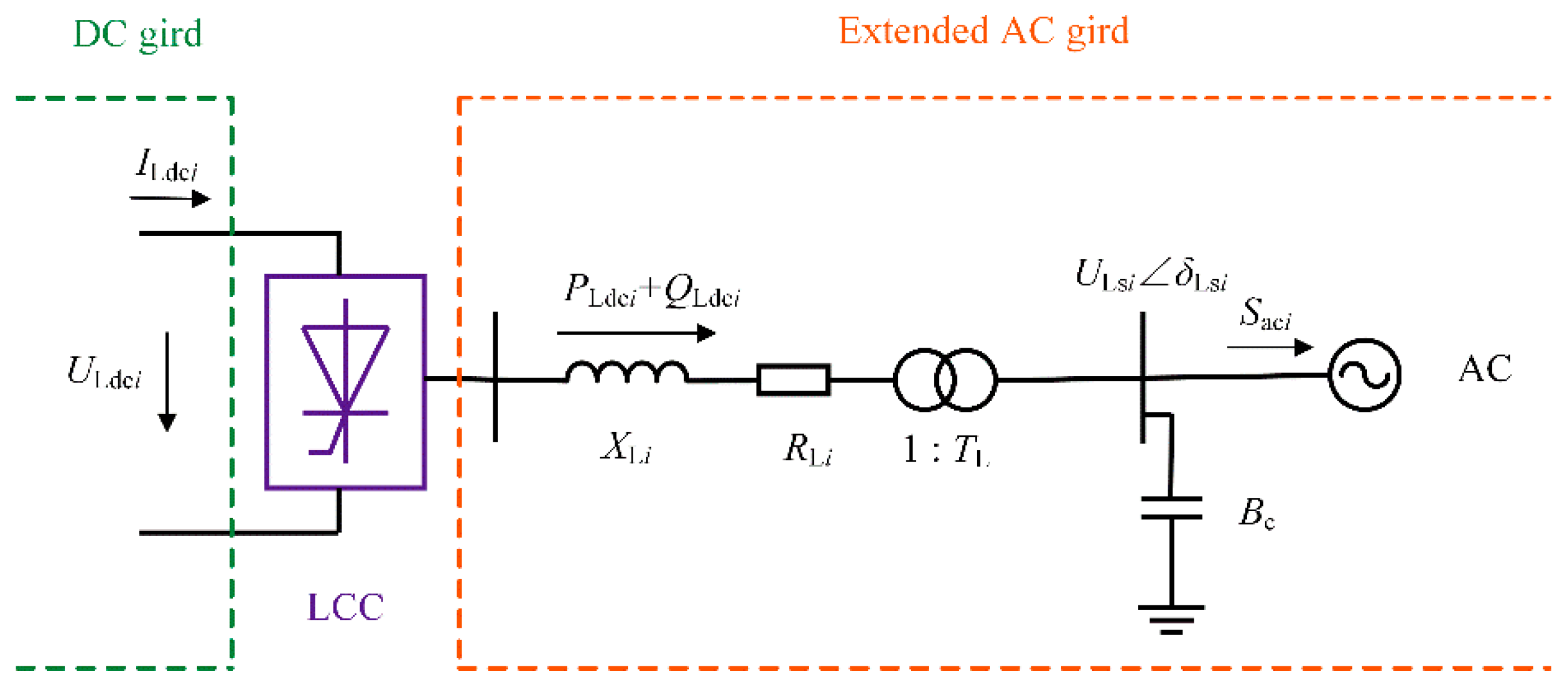
The basic unit of an LCC is a six-pulse converter, and the interface equation of the converter station is connected to the AC side. All the losses of converter station are borne by the AC grid. Figure 2 illustrates a simplified model of an LCC station.
In Figure 2, ILdci and ULdci are the DC current and the DC voltage of the LCC, respectively; XLi is the equivalent reactance of the LCC; RLi is the equivalent resistance of the LCC; TL is the transformer ratio of the LCC; ULsiδLsi is the AC bus voltage of the LCC; Bc is the filter susceptance of the LCC; and Saci = Paci + jQaci is the apparent power of the common connection point of the LCC. The converter station model of the LCC can be expressed as follows:
U L d c i = 3 2 T L U L s i n t π cos γ i 3 π X L i I L d c i n t
U L d c i = 3 2 T L U L s i n t k s π cos φ
I L s i = T L n t k s 6 π I L d c i
P L d c i = U L d c i I L d c i
Q L d c i = U L d c i I L d c i tan φ
P a c i = P L d c i + P Lloss i
Q a c i = Q L d c i + Q c
where γi is the control angle of the LCC; nt is the number of converter bridges; ks is a constant, which is typically equal to 0.995; φ is the power factor angle; ILsi is the current of the converter transformer; PLdci + jQLdci denotes power injections to inverter i; PLlossi is the converter loss, for which the calculation method will be specified below; Qc represents the generated reactive power of the filter susceptance Bc.

2.1.3. Converter Losses

The EC62751 standard recommends the use of electromagnetic transient simulation for calculation, followed by curve fitting to obtain an accurate model, which can be expressed as a quadratic function of the converter current. To explain the parameters of VSCs and LCCs in a unified way, if the subscript x in all equations in this paper is 0, the DC node is the converter-free access node; if x is L, the DC node is connected to an LCC; and if x is V, the DC node is connected to a VSC. The converter loss is expressed in the following equation.
P x loss i = = c i + b i I x i + a i I x i 2
In the equation, ai, bi, and ci are the loss characteristic coefficients. The converter that is connected to the DC node is an LCC, at this time Ixi = ILsi. The inverter that is connected to the DC node is a VSC, and Ixi = IVci, which can be calculated via the following equation:
I V c i = U V s i U c i Z V i

2.2. Improvement of the Alternating Iteration Method for AC–DC Power-Flow Calculation

2.2.1. Steady-State Model Adjustment of the DC Converter Station

In the iterative process, the traditional alternating iterative method solves the AC grid equation and the DC grid equation separately [29,30]. As the proportion of the DC load increases, the dimension of the DC grid equation increases, and the number of iterations increases.
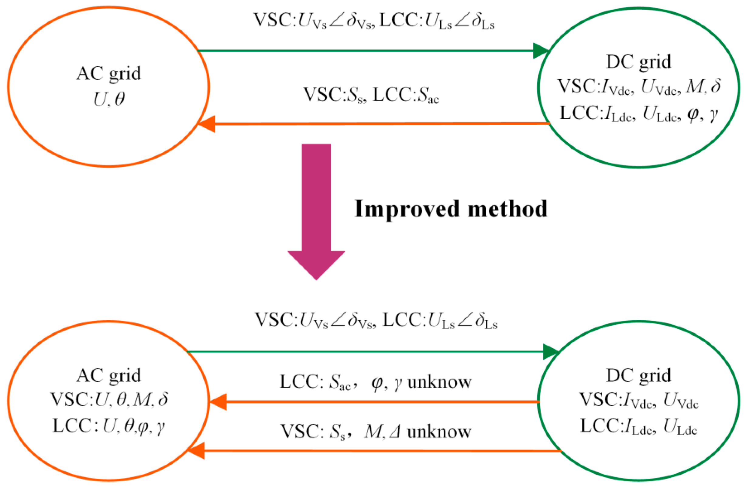
Based on the scenario that is described above, the traditional alternating iterative method model is modified as follows:
  • The interface equation of the converter is connected to the AC side, and all the losses of the converter stations will be on the AC grid.
  • The AC grid equation variables increase the interface equation variables of the converter. According to the converter type, for a VSC, the state variables δ and M of the DC system are merged into the AC flow equation for solving. For an LCC, the state variables φ and γ of the DC system are merged into the AC flow equation for solving.
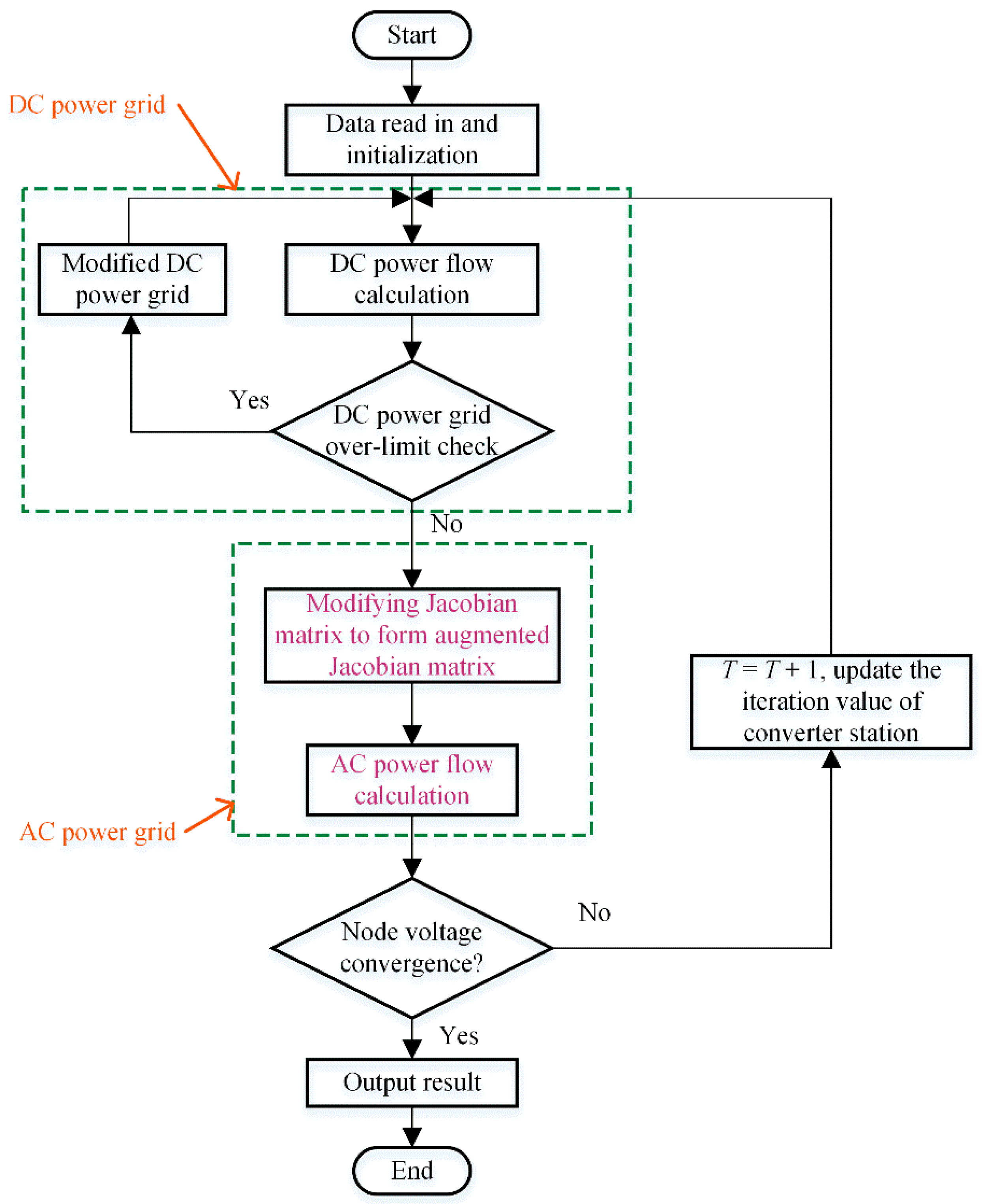
The modified alternating iteration method for AC–DC power-flow calculation considers the coupling relationship between the power flows, as illustrated in Figure 3. After modification, the control variables of the DC power grid are only related to DC parameters, which further enhances the flexibility of the DC control mode.

2.2.2. DC Grid Power-Flow Model

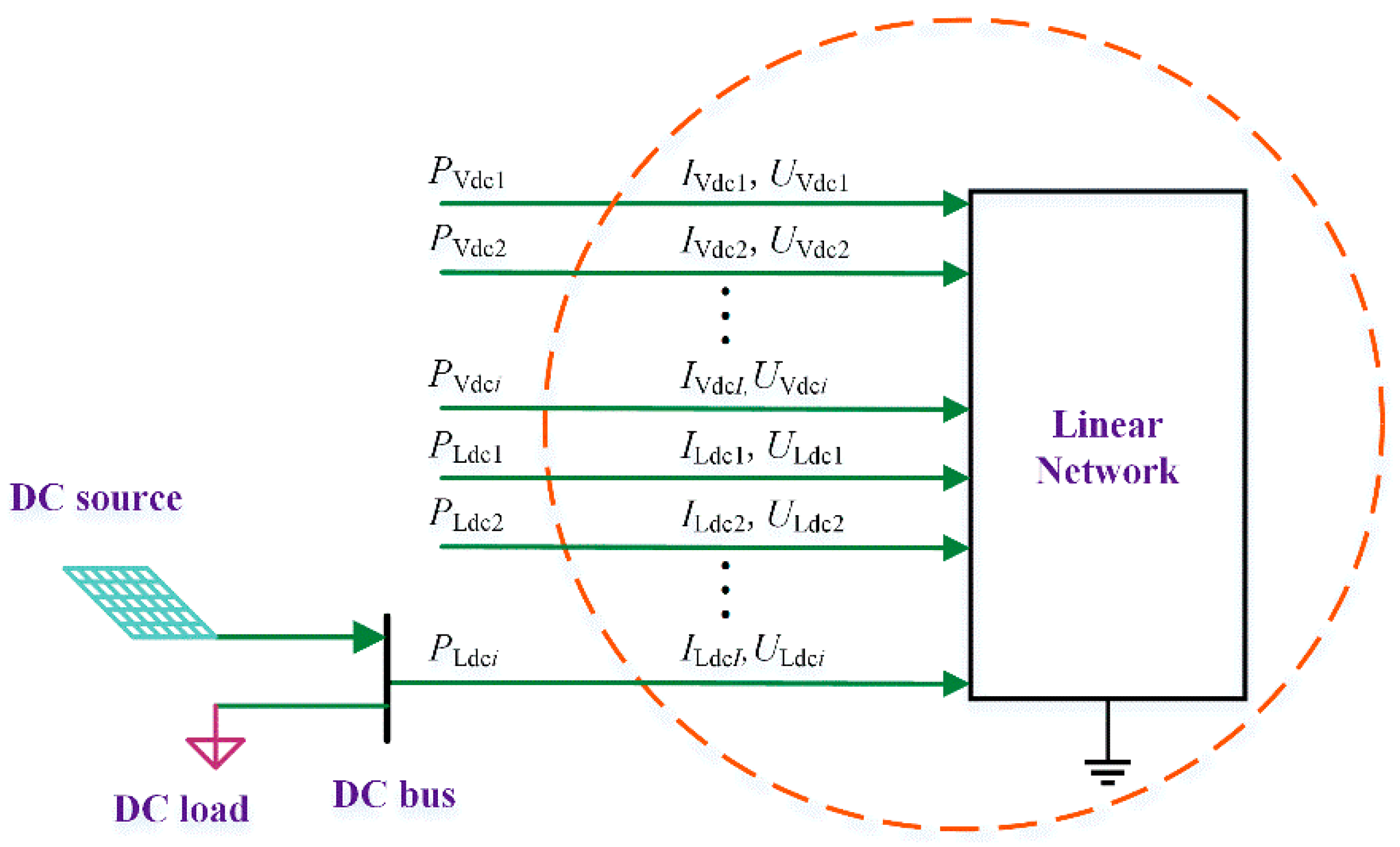
A DC power network is a pure resistance linear network, which can be described by the corresponding conductance matrix. In the above division of AC and DC systems, the DC power, DC loads, and LCC/VSC stations are treated as nonlinear components and are not included in the linear network, as illustrated in the following Figure 4.
For a DC grid with n DC nodes, the relationship between the node current and the node voltage can be expressed by the nodal equation:
I x d c i = Y dc U x d c i
In the equation, Ixdci = [Ixdc1, Ixdc2,…, Ixdcn]T is the node current vector; Uxdci = [Uxdc1, Uxdc2,…, Uxdcn]T is the node voltage vector; and Ydc is the DC network node conductance matrix.
In addition, the expressions of the injected power (Pxdci), current (Ixdci), and voltage (Uxdci) of the DC node are as follows:
P x d c i = I x d c i U x d c i
If the DC node contains DC power or a DC load, they must be added to perform the above calculation. Substituting Equation (13) into Equation (14):
P x d c i = j = 1 n Y i j U x d c j U x d c i
In the equation, Yij is an element of matrix Ydc.
Due to the use of self-commutated semiconductors and direct current vector control strategies, a VSC station has the flexibility to control the active and reactive variables. Active power control includes constant DC active power control, constant DC voltage control, constant DC current control, and droop control. Reactive power control includes constant AC reactive power control and constant AC voltage control [31,32].
The most common operation control method of an LCC is constant DC current control and extinction angle control [33]. In addition, constant DC active power control and constant DC voltage control can be applied, among other control modes [34].
From the above derivation, it is concluded that the converter imbalance equation that corresponds to the active power control is:
Δ P x d c i = P x d c i s j = 1 n Y i j U x d c j U x d c i
In the equation, Pxdcis is the specified active power.
In addition, the DC imbalance equations that correspond to the constant DC voltage control, constant DC current control, droop control, and extinction angle (trigger angle) control are:
Δ U x d c i = U x d c i s U x d c i
Δ I x d c i = I x d c i s j = 1 n Y i j U x d c j
Δ d 1 x i = U x d c i U x d c i s + k d r o o p x i ( j = 1 n Y i j U x d c j U x d c i P x d c i s )
Δ d L i = 2 T L U L s i X L i s i g n cos γ i s π 3 X L i n t s i g n U L d c i j = 1 n Y i j U L d c j
In the equations, Ixdcis and Uxdcis are the specified direct current and the specified direct voltage, and γ i s is the specified control angle for the LCC.
The above equations are developed based on the Taylor equation, and the matrix form of Newton’s power-flow correction equation is obtained by ignoring the high-order terms as follows:
Δ X = J D C Δ U
In the equation, ΔX = [⋯, ΔPxdc, ΔIxdc, Δd1x, ΔdLi, ⋯]T, ΔU is DC voltage vector for each node other than the constant DC voltage control, and JDC is the DC Jacobian matrix. If there is only one constant DC voltage control converter in the above equation, the matrix dimension is n−1, which is effectively reduced compared with the traditional alternating iterative matrix dimension.

2.2.3. AC Grid Power-Flow Model

For an AC node (without a converter), the power mismatch equation is:
Δ P a i = P a i U a i j i U j ( G i j cos θ i j + B i j sin θ i j ) Δ Q a i = Q a i U a i j i U j ( G i j sin θ i j B i j cos θ i j )
where subscript a denotes that the node is a pure AC node; Pai and Qai are the specified active power and reactive power for the node; j is connected to AC node i with a common connection node; Uai and Uj are the voltages of nodes i and j, respectively; Gij and Bij are the conductance and susceptance, respectively, of the AC node; and θij is the phase angle difference between nodes i and j, which is expressed as θij = θiθj.
For a node with the converter, according to the division of the AC system and the DC system that is specified above, the power mismatch equations are as follows:
Δ P t i = P t i U t i j i U j ( G i j cos θ i j + B i j sin θ i j ) P a c i Δ Q t i = Q t i U t i j i U j ( G i j sin θ i j B i j cos θ i j ) Q a c i
In the equations, subscript t denotes the DC node.
For VSCs:
P a c i = P s i ( δ c i , M i ) Q a c i = Q s i ( δ c i , M i )
The state variables δ and M of the DC system are merged into the AC flow equation for solving. Since there are two more variables to solve, new equations must be added. Assuming that the number of VSCs is nv, it is necessary to add 2nv equations. The original AC Jacobian matrix must be augmented to extend the 2nv dimensions. The supplementary equations are as follows:
Δ P V i = P V d c i P s i ( δ c i , M i ) + P V l o s s i
Δ Q V i = Q V r e f i Q s i ( δ c i , M i )
Combining the above four equations yields:
Δ P Δ Q Δ P V Δ Q V = H *   N * A P M A P δ J * L *     A Q M   A Q δ F P V δ s F P V U S P V M   S P V δ F Q V δ s F Q V U S Q V M S Q V δ Δ δ Δ U Δ M Δ δ c
where H*, N*, J*, and L* are the augmented Jacobian matrices after the addition of the state variables δ and M to the original AC Jacobian matrix; APM, APδ, AQM, A are the augmented Jacobian matrices of the AC active and reactive powers to state variables δ and M; F P V δ s , F P V U , F Q V δ s , F Q V U are the augmented Jacobian matrices of the active and reactive powers to the AC voltage phase angle and amplitude at common connection points of the VSC; and S P V M , S P V δ , S Q V M , S Q V δ are the augmented Jacobian matrices of the active and reactive powers to the state variables δ and M at common connection points of the VSC. The expression is as follows:
H *   = H + P s δ , N * = N + P s U J *   = J + Q s δ , L * = L + Q s U
A P M = U V s i μ i 2 U V d c i [ G cos ( δ V s i δ c i ) + B sin ( δ V s i δ c i ) ]
A P δ c = F P V δ = S P V δ = U V s i μ i M 2 U V d c i [ B cos ( δ V s i δ c i ) G sin ( δ V s i δ c i ) ]
A Q M = S Q V M = U V s i μ i 2 U V d c i [ B cos ( δ V s i δ c i ) G sin ( δ V s i δ c i ) ]
A Q δ c = F Q V δ s = S Q V δ = U V s i μ i M 2 U V d c i [ G cos ( δ V s i δ c i ) + B sin ( δ V s i δ c i ) ]
F P V U = 2 U V s G + 2 a ( U V s μ M 2 U V d c i ) Z 2 + b Z μ M 2 U V d c [ G cos ( δ V s δ c ) + B sin ( δ V s δ c ) ]
F Q V U = 2 U V s B μ M 2 U V d c [ B cos ( δ V s δ c ) G sin ( δ V s δ c ) ] 2 U V s B f
S P V M = U V s i μ i 2 U V d c i [ G cos ( δ V s i δ c i ) + B sin ( δ V s i δ c i ) ] 2 a ( U V s μ M 2 U V d c i ) Z 2 μ 2 U V d c i b Z μ 2 U V d c i
For LCCs:
P a c i = P a c i ( I L d c i , U L d c i ) Q a c i = Q a c i ( I L d c i , U L d c i , φ )
In the equations, the state variable φ of the DC grid is merged into the AC flow equation for solving. To make the equations solvable, a new equation must be added. The corresponding augmentation terms must be added to the original AC Jacobian matrix. In addition, to obtain the control variable γ, according to Equations (4) and (5), the supplementary equations are as follows:
Δ d 1 i = U L d c i 3 2 T L U L s i n t π cos γ i + 3 π X L i I L d c i n t
Δ d 2 i = U L d c i 3 2 T L U L s i n t k s π cos φ
If the tap of the converter transformer is determined, from Equations (36)–(38), the following can be obtained:
Δ P Δ Q Δ d 1 Δ d 2 = H L *   N L *   A P γ A P φ J L *   L L *       A Q γ   A Q φ F d 1 δ F d 1 U S d 1 γ   S d 1 φ F d 2 δ F d 2 U S d 2 γ S d 2 φ Δ δ Δ U Δ γ Δ φ
In the equations, A P γ , A P φ , A Q γ , A Q φ are the augmented Jacobian matrices of the AC active and reactive powers to state variables φ and γ; F d 1 δ , F d 1 U , F d 2 δ , F d 2 U are the augmented Jacobian matrices of the supplementary equation of an LCC to the AC voltage phase angle and amplitude; and S d 1 γ , S d 1 φ , S d 2 γ , S d 2 φ are the augmented Jacobian matrices of the supplementary equation of an LCC to state variables φ and γ. The expression is as follows:
A Q φ = U L d c i I L d c i sec 2 φ
F d 1 U = 3 2 T L n t π cos γ i
S d 1 γ = 3 2 T L U L s i n t π
F d 2 U = 3 2 T L n t k s π cos φ
S d 2 φ = Δ d 2 φ = 3 2 T L U L s i n t k s π sin φ
According to the above analysis, for LCCs, assuming that the number of LCCs is nl, it is necessary to increase the 2nl dimensions on the basis of the original AC Jacobian matrix. Although the Jacobian matrix dimensionality is increased, the corresponding extended Jacobian matrix is simple to calculate, easy to implement, and has fewer nonzero elements.

2.2.4. Dimensions of the Jacobian Matrix of the Improved Alternating Iteration Method

  • AC Jacobian Matrix
According to the above analysis, assuming that the number of VSCs is nv, the original AC Jacobian matrix must be augmented by 2nv dimensions. For LCCs, assuming that the number of LCCs is nl, it is necessary to increase the 2nl dimensions on the basis of the original AC Jacobian matrix.
2.
DC Jacobian Matrix
In the traditional alternating iteration method, for VSCs, the number of VSCs is assumed to be nv, and the DC grid contains four variables to solve, thereby requiring 4nv equations. Similarly, for LCCs, the number of LCCs is assumed to be nl, and the DC grid contains four variables to solve, thereby requiring 4nl equations. Assuming that single-point voltage control is adopted in the DC power grid, the dimension of the DC Jacobian matrix is 4(nv + nl) − 1 in the traditional alternating iteration method. In the improved method, the dimension of the DC Jacobian matrix is only (nv + nl) − 1, which is 3(nv + nl) less than the traditional method. The main reason is that in the process of solving for VSCs, the state variables δ and M of the DC system are merged into the AC power-flow equation for solution; and for LCCs, the state variables γ and φ of the DC power grid are merged into the AC power-flow equation for solution.

3. Algorithm Flow and Date

If the system does not contain an LCC of extinction angle (trigger angle) control, the DC state variables are not related to the AC side. In contrast, if an LCC contains extinction angle (trigger angle) control, the DC state variables are related to the AC bus voltage of the LCC of extinction angle (trigger angle) control, regardless of the other AC state quantities. When calculating the power flow of the DC subsystem, the AC bus voltage of the LCC is regarded as a constant value.

3.1. Iterative Initial Value of the DC Grid

In DC power-flow calculation, the parameters that characterize the operation status of each DC node are the DC voltage, DC current, DC power, and control angle (the converter is an LCC) [35,36,37]. Depending on whether the variables are known, the initial value of the DC node iteration is selected, as presented in Table 2.

3.2. Control Mode of the DC Power Grid

It is assumed that there are n DC nodes in the DC grid and that the control mode is single-point voltage control. Only one DC node uses constant DC voltage control to control the voltage, to ensure that the DC voltage tracks the reference value of the voltage [38].
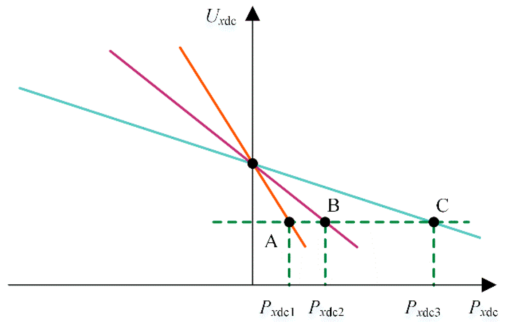
In an n-node network with multipoint voltage droop control, there are m DC nodes with DC voltage droop control. Their control characteristics are expressed as:
f i = U x d c i U x d c i s + k d r o o p x i ( P x d c i P x d c i s ) = 0
In the equation, i = 1, 3,…, m and kdroopxi is the droop coefficient.
If a power shortage in the network causes the DC voltage to droop, the m-voltage droop control stations increase the power that is injected into the network according to their own operating curves. The power unit operates on a drooping curve with various coefficient values, and the output power differs at the same DC bus voltage [39].
Suppose Figure 5 shows the drooping curves of three moments of the same unit in the system, which initially runs at point B. If the unit must output more power, the coefficient must be reduced; if the unit must reduce its power output, the coefficient must be increased. During the operation of the system, the transmission power of the unit can be adjusted by dynamically adjusting the coefficient of the drooping curve.

3.3. Operation Analysis of the DC Power Grid

For DC power-flow calculation, it is necessary to check whether the DC power grid variables exceed the limit. At the same time, during normal operation, in order to ensure the safe operation of a VSC converter station, the VSC converter station needs to adjust its control mode in time so that it can operate in a safe area [40].

3.3.1. Over-Limit Verification of the DC Power Grid

If the node voltage exceeds the limit, it is necessary to modify the voltages of all constant voltage control or droop control stations because the resistance of the DC network is low and the DC voltage of the whole network is approximately the same.
U x d c i s = U x d c i s α max ( Δ U d c lim j )
In the equation, α is the margin coefficient, which is greater than 1.0, and ∆Udclimj is the overlimit voltage of the jth node in the DC network.
If the node power of a droop control station exceeds the limit and multipoint voltage droop control is adopted, there are voltage station nodes whose node power does not exceed the limit. According to the following equations, the powers of overlimit and within-limit voltage stations are modified:
P x d c i s = P x d c i s α Δ P d c lim i i V 1
P x d c i s = P x d c i s α i V 1 Δ P d c lim i n V 2 j V 2
In the equations, iV1 is the droop control station node with a power that exceeds the limit, jV2 is the droop control station node with a power that does not exceed the limit, n V 2 is the number of elements in V2, and ∆Pdclimi denotes the DC power that exceeds the limit of the ith droop control station node.

3.3.2. Analysis of VSC Operation Characteristics

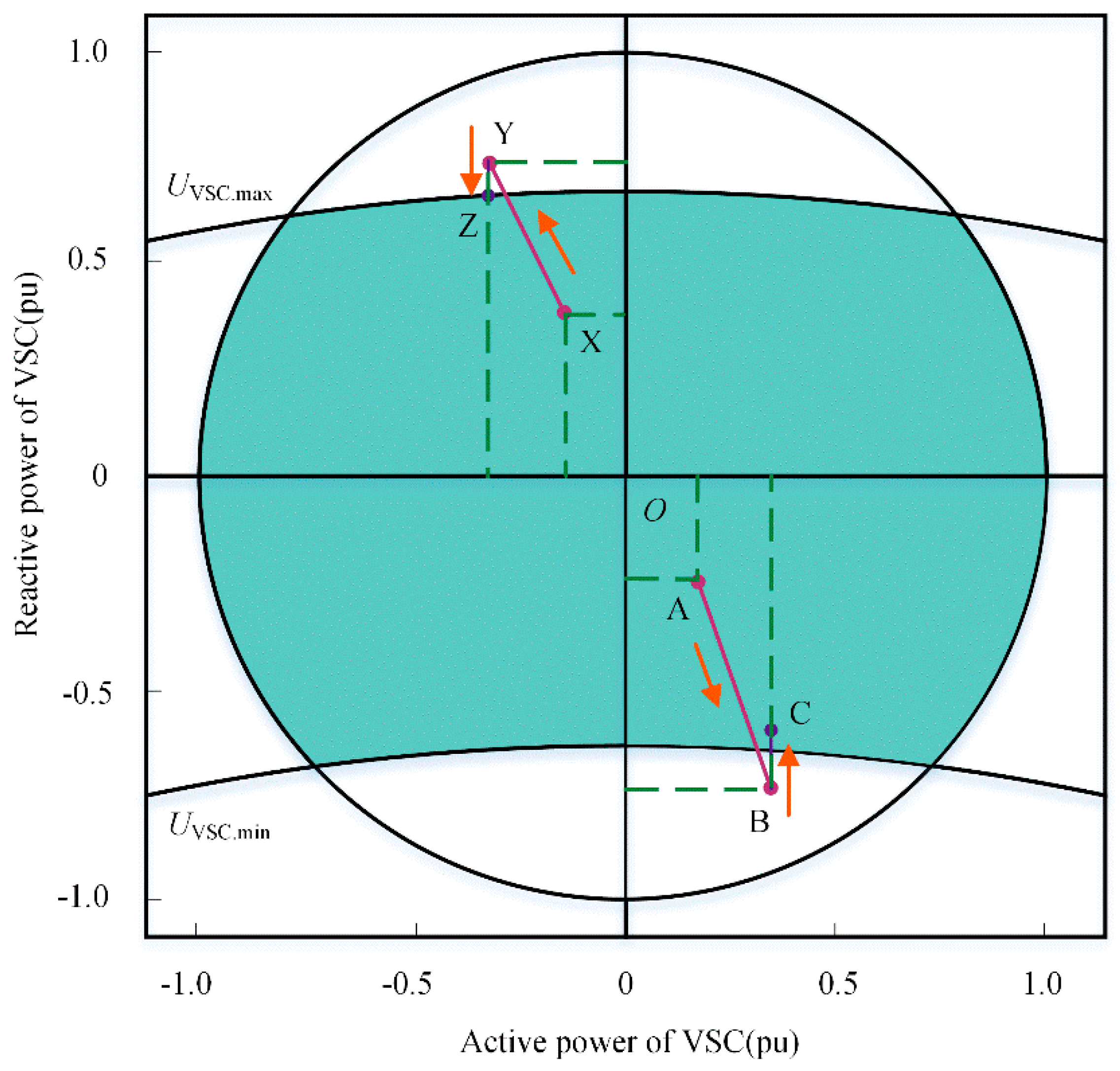
Figure 6 shows the safe operation area of an VSC converter station considering the voltage constraints and transmission capacity constraints of converter stations. The upper and lower arcs in the figure are the corresponding reactive power boundaries when the converter bus voltage operates at the upper and lower limits. The circular area is the transmission capacity constraint of the converter, the rectifier operation area is on the left, the inverter operation area is on the right, and the shaded part is the actual operation area of the VSC converter station.
As shown in Figure 6, if the reactive power control mode of the converter station is set to constant reactive power control, it is at point A in the figure during normal operation. If the load of the AC PCC node or adjacent nodes increases, the amplitude of the PCC voltage will be reduced due to insufficient reactive power, which will lead to the voltage of converter bus being lower than its lower limit, as shown at point B. At this time, it is necessary to change the constant reactive power control into constant AC voltage control to provide a reactive power support capacity for the system to improve the AC node voltage. The system operation point will be moved to point C to maintain the voltage of the VSC converter station within a reasonable range. If the reactive power control mode of the converter station is set to constant AC voltage control, it is at point X during normal operation. If the load of the PCC node continues to increase significantly, the reactive power injected into the AC system PCC by the VSC converter station will also increase, resulting in the converter bus voltage being higher than its upper limit, as shown at point Y. At this time, the control mode of the VSC converter station shall be changed from constant AC voltage control to constant reactive power control. The set value of reactive power is the maximum reactive power injection value under the constraint of converter transmission capacity. The system operates at point Z to avoid out-of-limit power flow.

3.4. Algorithm Flow

The key to solving an AC–DC power flow via alternating iteration is the coupling relationship between the AC and DC power flows. In the traditional alternating iteration method for AC–DC power-flow calculation, the influence of the AC system on the DC system is generated by the voltage of the AC bus. If the voltage is known, the power flow of the DC system can be solved independently. The influence of the DC system on the AC system is generated by the AC injection power of the converter station. If the power is known, the power flow of the AC system can also be solved independently. In this paper, the traditional alternating current and power-flow calculation alternating iterative method model is modified. After modification, the influence of the AC system on the DC system is still generated by the AC bus voltage, but the effect of the DC system on the AC system is generated by the DC injection power of the converter station. At this time, the state variables of the DC power grid only include the DC current and the DC voltage. The calculation process of the improved alternating iterative method is illustrated in Figure 7. First, the data are read for DC grid power-flow calculations, and if the DC grid does not exceed the limit, the AC-side augmented Jacobian matrix is subsequently obtained for AC-side power-flow calculations.

3.5. Test System

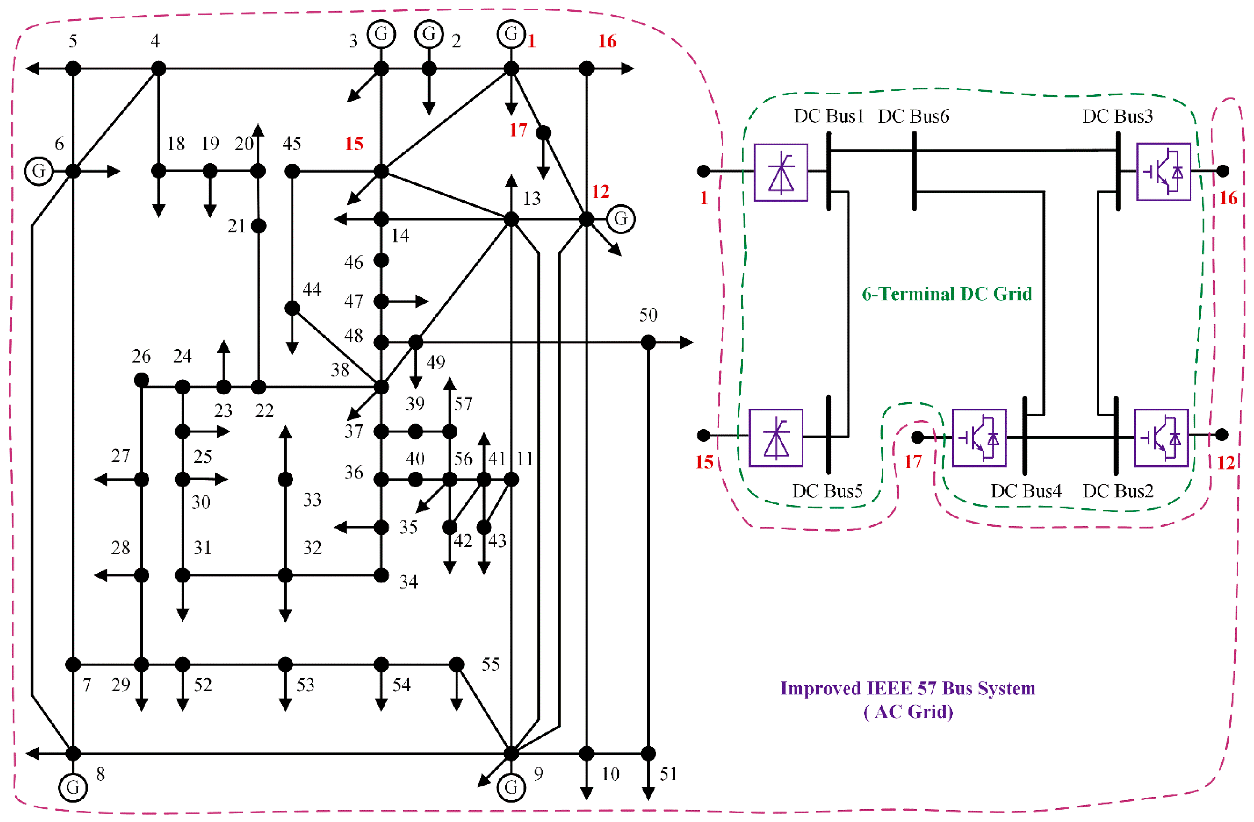
To evaluate the accuracy and effectiveness of the improved alternating iteration power-flow algorithm for AC–DC power grids, a modified IEEE 57 bus system with six terminals of DC power grids and a CIGRE B4 bus system are simulated in MATLAB. It is compared with the method proposed in the literature [28,41]. The case-study settings are listed in Table 3.

3.5.1. Case 1

In Case 1, a modified IEEE 57 bus system is considered. A six-terminal DC power grid with a voltage level of ±200 kV was added to the system. The topological structure is illustrated in Figure 8. The reference capacity of the AC–DC network is 100 MVA. The reference voltage of the DC power grid is 200 kV. Converter stations 1 and 5 are LCCs, DC bus 6 consists of pure DC nodes without a converter, and the remaining are VSCs. The AC-side parameters (which include the loss characteristics) and the DC-grid-line parameters of the five converter stations are listed in Table 4 and Table 5. The DC grid adopts a single-point voltage control. The control methods and reference values are specified in Table 6.

3.5.2. Case 2

In an AC–DC hybrid power grid, VSC control strategies are flexible and diverse, so the power-flow calculation of AC–DC hybrid power grids considering control strategies becomes an important problem that needs to be studied urgently. Reference [42] proposed a power-flow model of an AC–DC hybrid power grid considering VSC control strategy, and flexibly realized a power-flow calculation of the hybrid power grid under different control strategies. However, the unified iterative method was used to solve the model, and the program inheritance was poor. With the expansion of DC network nodes, the calculation amount will increase accordingly, resulting in a decrease in the iterative speed. In this paper, the improved alternating iteration method is used to establish the DC power-flow calculation model under various control modes, and an AC–DC power-flow decoupling calculation with LCC/VSC hybrid DC is realized. In case 2, the DC grid uses multipoint voltage droop control, in which converter stations 1 and 2 are voltage stations, to realize voltage droop control, as presented in Table 7. The remaining stations are power stations, and the control method is the same as in case 1.

3.5.3. Case 3

Case 3 uses the CIGRE B4 bus system [43], which was proposed by the B4 Working Group of the International Large Power Grid Conference. The parameters of the system are specified in the literature [44]. The system has 11 AC buses and 15 DC buses, as illustrated in Figure 9. To test the converter models and control methods that are proposed in this paper, the converter control methods in the original example are modified as follows: (1) Cm-A1 is set to an LCC using droop control; (2) Cm-B2 is set to an LCC with fixed angle control; (3) Cm-B3 is set to an LCC using droop control.
The converter drooping coefficient is assumed to be 0.1, and the converter loss parameters are assumed to be a = 0.01, b = 0.04, and c = 0. Partial results are listed in Table 8. The calculation results are approximately consistent with the results of the original example, and the accuracy of the method is demonstrated again.

4. Results and Discussion

The traditional alternating iteration method and the method in this paper are applied to case 1. The results of the two algorithms are compared in Table 9. The maximum error of all state variables in the AC–DC power grid is 7.9 × 10⁻⁵; the improved alternating iteration algorithm in this paper is accurate.
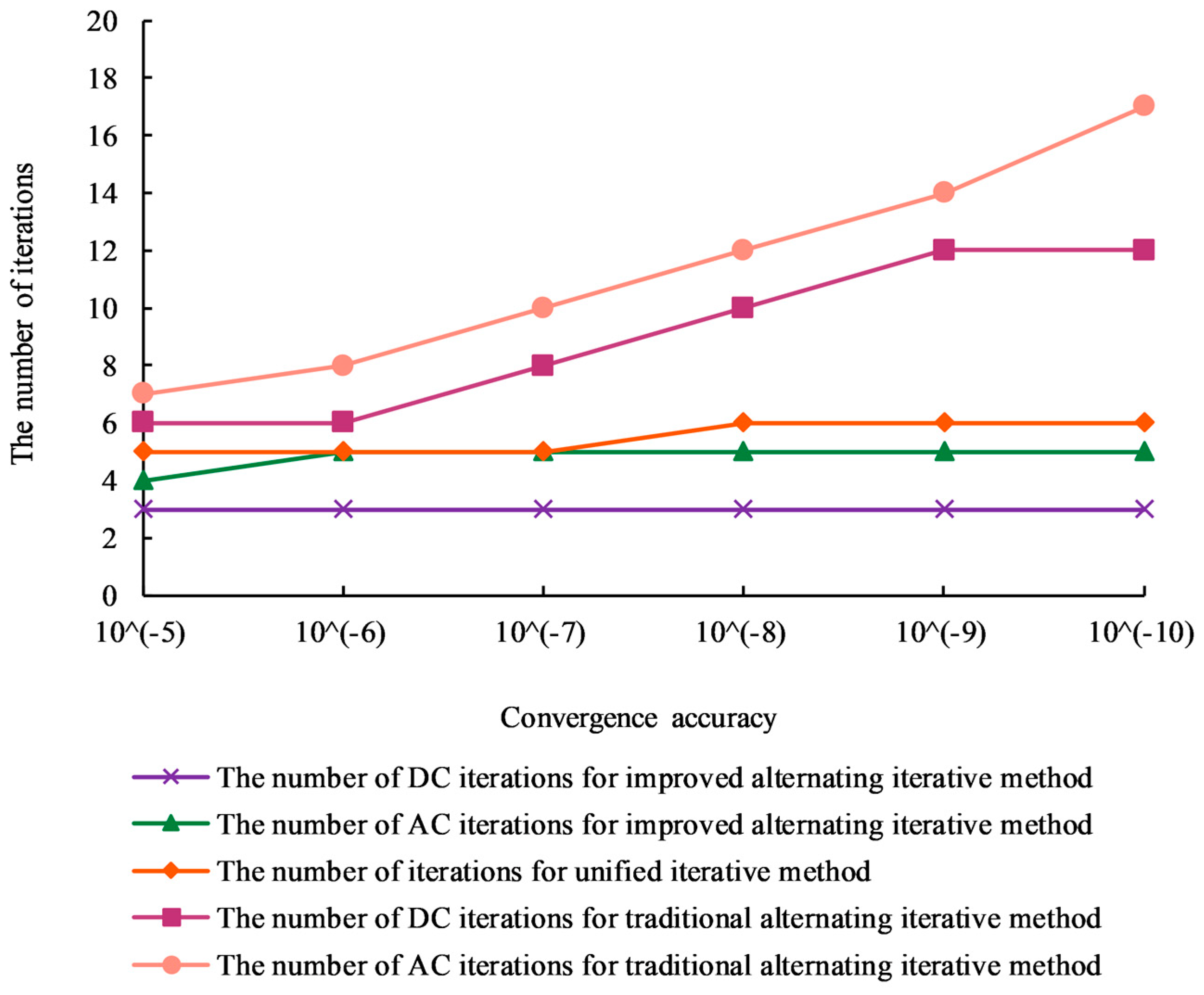
In reference [45], a hybrid AC–DC power-flow alternative iterative algorithm is proposed to solve the current difficulties in the power-flow calculation of LCC–VSC hybrid DC transmission systems. However, the initial value should be reasonably selected to ensure power-flow convergence and accurate results. Figure 10 compares three methods: the method that is proposed in this paper, the traditional alternating iteration method, and the unified iteration method. The number of DC power-flow iterations, the number of AC power-flow iterations, and number of iterations of the improved alternating iterative method are all less than those of the traditional alternating iterative method. Moreover, the improved method is not sensitive to an increase in the convergence precision: the number of iterations remains approximately unchanged. The number of iterations increases linearly with the convergence precision. Compared with the unified iterative method, the method has similar convergence, and the number of iterations does not increase linearly with the accuracy.
Considering the convergence accuracy of 10−7 as an example, the differences in the Jacobian matrix dimension, the number of iterations, and the calculation time between the traditional AC–DC power-flow algorithm and the proposed algorithm are examined. The results are presented in Table 10. According to the table, for case 1, the dimension of the DC Jacobian matrix is reduced by 18 compared with the traditional alternating iteration method. All three methods can converge. Under the same convergence accuracy, the difference in the number of iterations is substantial. The method that is proposed in this paper has the advantages of the unified iteration method in terms of the number of iterations and the convergence speed.
In the power-flow calculation results, the voltage, current, and power of the AC grid are within reasonable ranges. The power flow of the converter station accurately tracks the reference value. The power-flow calculation results of the DC power grid are presented in detail in Table 11, in which the DC voltage and the DC power of DC node 1 and DC node 2 satisfy the droop control characteristics.
If the DC power of DC bus 3 is increased to 0.7, the DC powers of DC bus 1 and DC bus 2 are 0.7013 and 0.9573, respectively, while the original drooping coefficient of the converter station is unchanged. At this time, the voltages of DC bus 1 and DC bus 2 are 0.9903 and 0.9933, respectively. By changing the drooping coefficient, the original drooping coefficients of DC bus 1 and DC bus 2 are reduced by 0.02 and increased by 0.02, respectively. The powers of the DC buses are 0.5027 and 1.0520, and the DC voltages are 0.9909 and 0.9989. The above conditions all satisfy the droop control requirements.
The calculation results demonstrate that the improved alternating iterative method is suitable for single-point voltage control and multipoint voltage droop control and can accurately calculate AC–DC power flow. For the control methods of multipoint voltage control and voltage droop control with a dead zone, the improved method of this paper is still suitable.
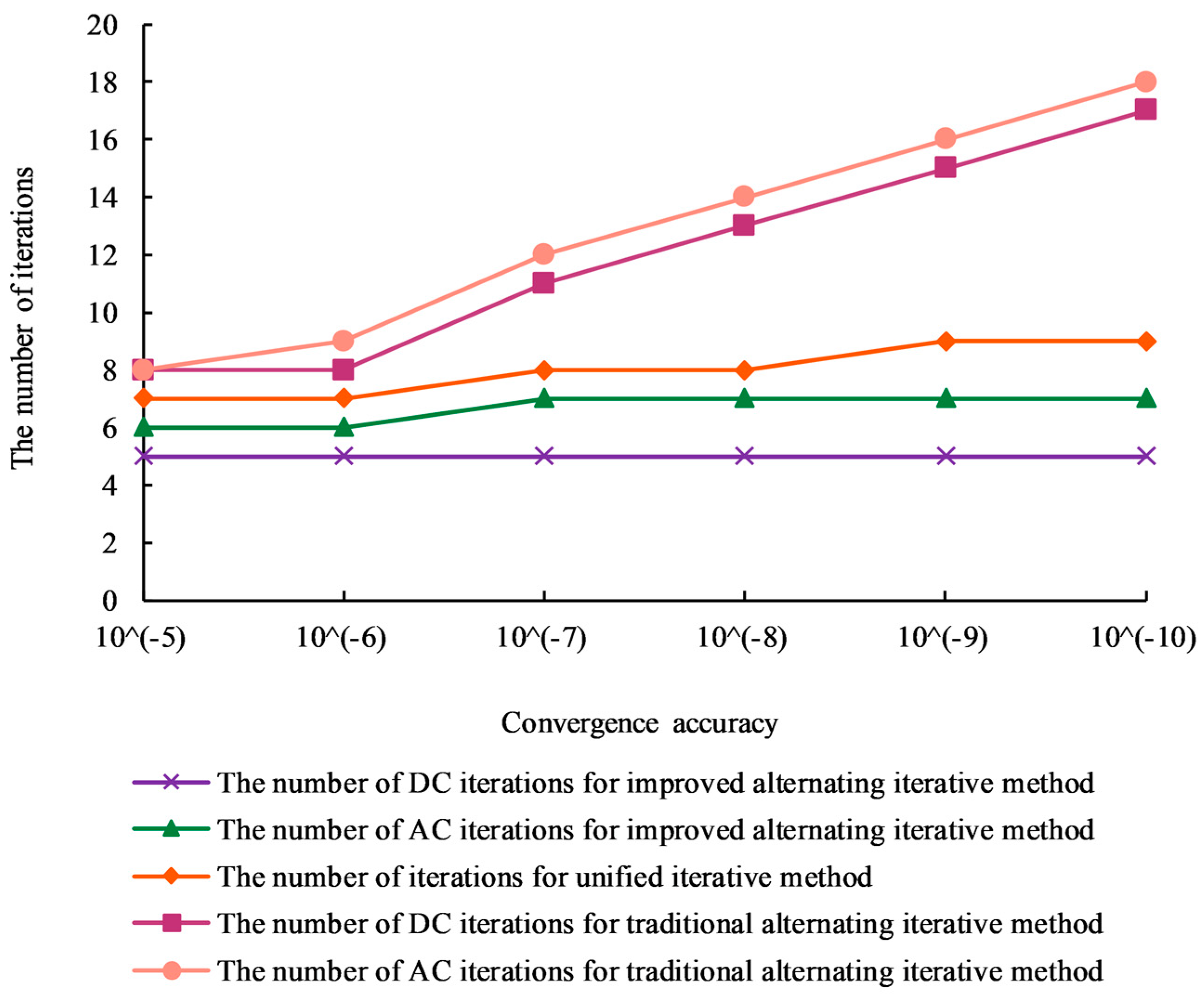
The CIGRE B4 node system has 11 AC buses and 14 DC buses. Compared with other DC bus systems, it has more DC buses; hence, it is more suitable for analyzing the improved AC–DC calculation method. Figure 11 compares the proposed method, the traditional alternating iteration method, and the unified iteration method in terms of the number of iterations. With an increase in the number of DC buses, the number of iterations of the improved alternating iterative method does not increase significantly. In contrast, the number of iterations of the traditional alternating iteration method and the unified iteration method increases substantially. Moreover, under the proposed method, with an increase in the convergence precision, the number of iterations remains approximately unchanged. Under the traditional iteration method, with an increase in convergence accuracy, the number of iterations increases more substantially.
Similarly, the convergence accuracy of 10−7 is considered as an example to illustrate the differences between the traditional AC–DC power-flow algorithm and the proposed algorithm in terms of the Jacobian matrix dimension, the number of iterations, and the calculation time. The results are presented in Table 12. Compared with the traditional alternating iteration method, the dimensions of the DC Jacobian matrix in case 3 are reduced by 45 and the number of iterations is significantly reduced.

5. Conclusions

In traditional alternating iterations, due to the poor coupling between AC and DC, multiple iterations are required to achieve convergence of the power-flow calculation results. With the increasing scale of the DC grid, this problem will become more critical. In light of this situation, based on the traditional alternating iterative method, this paper proposes an improved power-flow calculation algorithm for AC and DC grids with LCCs and VSCs. The main conclusions are as follows:
  • In the actual operation of the grid, the method is applicable to various types of converter, various converter control modes, various DC grid control methods, and reasonable adjustments of the DC grid variable constraints and operation modes.
  • The converter interface model is divided into the AC side and the DC side, the influence of the DC side on the AC side is considered, and an augmented Jacobian matrix model with LCC/VSC interface equation variables is established. According to the type of converter, control mode, and DC grid strategy, a DC grid power-flow calculation model under various control modes is established to realize an AC–DC power-flow decoupling calculation with LCC/VSC.
  • The computation burden of the power-flow calculation of the DC grid is reduced, especially for the calculation of the actual AC and DC power flow with many DC buses, which can reduce the number of iterations, improve the calculation speed, and realize the convergence of unified iteration.

Author Contributions

Conceptualization, D.Y. and S.G.; methodology, D.Y. and S.G.; software, D.Y. and X.Z.; validation, D.Y. and S.G.; formal analysis, D.Y. and Y.L.; investigation, X.Z.; data curation, S.G.; writing—original draft preparation, D.Y. and S.W.; writing—review and editing, T.E.S.; visualization, D.Y. and X.Z.; supervision, S.G.; project administration, X.Z. All authors have read and agreed to the published version of the manuscript.

Funding

This research was funded by the national key research and development program of China, grant number 2016YFB0900602 and the technology projects of state grid corporation of China, grant number 52094017000W.

Institutional Review Board Statement

Not applicable.

Informed Consent Statement

Not applicable.

Data Availability Statement

Data sharing not applicable.

Acknowledgments

This work is supported in part by the national key research and development program of China and in part by the technology projects of state grid corporation of China.

Conflicts of Interest

The authors declare no conflict of interest.

References

  1. Shu, D.; Yang, H.; He, G. A Harmonic Phasor Domain Cosimulation Method and New Insight for Harmonic Analysis of Large-Scale VSC-MMC Based AC/DC Grids. IEEE Trans. Power Electron. 2021, 36, 3909–3924. [Google Scholar] [CrossRef]
  2. Huang, M.; Wei, Z.; Lin, Y. Forecasting-aided state estimation based on deep learning for hybrid AC/DC distribution systems. Appl. Energy 2022, 306, 118119. [Google Scholar] [CrossRef]
  3. Liu, Y.; Song, Y.; Wang, Z.; Shen, C. Optimal Emergency Frequency Control Based on Coordinated Droop in Multi-Infeed Hybrid AC-DC System. IEEE Trans. Power Syst. 2021, 36, 3305–3316. [Google Scholar] [CrossRef]
  4. Heidari, S.; Hatami, A.; Eskandari, M. An intelligent capacity management system for interface converter in AC-DC hybrid microgrids. Appl. Energy 2022, 316, 119112. [Google Scholar] [CrossRef]
  5. Monteiro, V.; Martins, J.S.; Aparício Fernandes, J.C.; Afonso, J.L. Review of a Disruptive Vision of Future Power Grids: A New Path Based on Hybrid AC/DC Grids and Solid-State Transformers. Sustainability 2021, 13, 9423. [Google Scholar] [CrossRef]
  6. Bayati, N.; Balouji, E.; Baghaee, H.R.; Hajizadeh, A.; Soltani, M.; Lin, Z.; Savaghebi, M. Locating high-impedance faults in DC microgrid clusters using support vector machines. Appl. Energy 2022, 308, 118338. [Google Scholar] [CrossRef]
  7. Yu, X.; Xiao, L. A DC Fault Protection Scheme for MMC-HVDC Grids Using New Directional Criterion. IEEE Trans. Power Deliv. 2021, 36, 441–451. [Google Scholar] [CrossRef]
  8. Adinolfi, G.; Ciavarella, R.; Graditi, G.; Ricca, A.; Valenti, M. A Planning Tool for Reliability Assessment of Overhead Distribution Lines in Hybrid AC/DC Grids. Sustainability 2021, 13, 6099. [Google Scholar] [CrossRef]
  9. Yang, G.; Dong, P.; Liu, M.; Wu, H. Research on random fuzzy power flow calculation of AC/DC hybrid distribution network based on unified iterative method. IET Renew. Power Gener. 2021, 15, 731–745. [Google Scholar] [CrossRef]
  10. Zhu, Z.; Liu, D.; Liao, Q.; Tang, F.; Zhang, J.; Jiang, H. Optimal Power Scheduling for a Medium Voltage AC/DC Hybrid Distribution Network. Sustainability 2018, 10, 318. [Google Scholar] [CrossRef] [Green Version]
  11. Xiao, H.; Pei, W.; Deng, W.; Ma, T.; Zhang, S.; Kong, L. Enhancing risk control ability of distribution network for improved renewable energy integration through flexible DC interconnection. Appl. Energy 2021, 284, 116387. [Google Scholar] [CrossRef]
  12. Huang, Y.; Ai, X.; Fang, J.; Yao, W.; Wen, J. Holomorphic embedding approach for VSC-based AC/DC power flow. IET Gener. Transm. Distrib. 2020, 14, 6239–6249. [Google Scholar] [CrossRef]
  13. Anbuselvi, S.V.; Kumudini Devi, R.P.; Vallinayagam, A.S.; Vignesh, V.; Gomis-Bellmunt, O. A Generalized sequential AC/DC power flow algorithm for VSC MTDC system with series interline DC current flow controller. Electr. Power Syst. Res. 2022, 209, 107972. [Google Scholar] [CrossRef]
  14. Ali, M.A.; Kamel, S.; Hassan, M.H.; Ahmed, E.M.; Alanazi, M. Optimal Power Flow Solution of Power Systems with Renewable Energy Sources Using White Sharks Algorithm. Sustainability 2022, 14, 6049. [Google Scholar] [CrossRef]
  15. Zhang, T.; Mu, Y.; Wang, X.; Deng, Y.; Song, Y.; Yuan, K.; Jia, H. Convex Approximation Algorithm for AC/DC Distribution Network with Energy Router. Front. Energy Res. 2021, 9, 731944. [Google Scholar] [CrossRef]
  16. Sun, Y.; Xia, D.; Gao, Z.; Wang, Z.; Li, G.; Lu, W.; Wu, X.; Li, Y. Probabilistic load flow calculation of AC/DC hybrid system based on cumulant method. Int. J. Electr. Power Energy Syst. 2022, 139, 107998. [Google Scholar] [CrossRef]
  17. Munisamy, V.; Sundarajan, R.S. Hybrid technique for load frequency control of renewable energy sources with unified power flow controller and energy storage integration. Int. J. Energy Res. 2021, 45, 17834–17857. [Google Scholar] [CrossRef]
  18. Silva, D.N.d.; Pereira Júnior, B.R.; Costa, G.R.M.d. A novel MILP-Newton approach for power flow analysis. IET Gener. Transm. Distrib. 2020, 15, 518–532. [Google Scholar] [CrossRef]
  19. Foti, M.; Mavromatis, C.; Vavalis, M. Decentralized blockchain-based consensus for Optimal Power Flow solutions. Appl. Energy 2021, 283, 116100. [Google Scholar] [CrossRef]
  20. Grangereau, M.; van Ackooij, W.; Gaubert, S. Multi-stage Stochastic Alternating Current Optimal Power Flow with Storage: Bounding the Relaxation Gap. Electr. Power Syst. Res. 2022, 206, 107774. [Google Scholar] [CrossRef]
  21. Zhang, Y.; Meng, X.; Malik, A.; Wang, L. The use of analytical converter loss formula to eliminate DC slack/droop bus iteration in sequential AC-DC power flow algorithm. Int. J. Electr. Power Energy Syst. 2022, 137, 107596. [Google Scholar] [CrossRef]
  22. Rehman, B.; Liu, C. AC/DC multi-infeed power flow solution. IET Gener. Transm. Distrib. 2019, 13, 1838–1844. [Google Scholar] [CrossRef]
  23. Yalcin, F.; Arifoglu, U. A new sequential AC-DC power flow algorithm for multi-terminal HVDC systems. IEEJ Trans. Electr. Electron. Eng. 2017, 12, S65–S71. [Google Scholar] [CrossRef]
  24. Fernandez-Perez, J.-C.; Echavarren Cerezo, F.M.; Rodriguez, L.R. On the Convergence of the Sequential Power Flow for Multiterminal VSC AC/DC Systems. IEEE Trans. Power Syst. 2018, 33, 1768–1776. [Google Scholar] [CrossRef]
  25. Sun, Y.; Wu, X.; Tang, G.; Li, G. A Nodal Impedance Matrix Based Gauss-Seidel Method on Steady State Power Flow Calculation of DC Power Grid. Proc. CSEE 2015, 35, 1882–1892. [Google Scholar] [CrossRef]
  26. Wu, Z.; Yin, Z.; Tang, X. An AC/DC Decoupled Hybrid Power Flow Algorithm for Hybrid Power System. Proc. CSEE 2016, 36, 937–944. [Google Scholar] [CrossRef]
  27. Beerten, J.; Belmans, R. Development of an open source power flow software for high voltage direct current grids and hybrid AC/DC systems: MATACDC. IET Gener. Transm. Distrib. 2015, 9, 966–974. [Google Scholar] [CrossRef]
  28. Chai, R.; Zhang, B.; Bo, Z. Alternating Iterative Power Flow Algorithm for Hybrid AC/DC Networks Containing DC Grid Based on Voltage Source Converter. Autom. Electr. Power Syst. 2015, 39, 7–13. [Google Scholar] [CrossRef]
  29. Renedo, J.; Ibrahim, A.A.; Kazemtabrizi, B.; García-Cerrada, A.; Rouco, L.; Zhao, Q.; García-González, J. A simplified algorithm to solve optimal power flows in hybrid VSC-based AC/DC systems. Int. J. Electr. Power Energy Syst. 2019, 110, 781–794. [Google Scholar] [CrossRef] [Green Version]
  30. Rosales-Muñoz, A.A.; Montano, J.; Grisales-Noreña, L.F.; Montoya, O.D.; Andrade, F. Optimal Power Dispatch of DGs in Radial and Mesh AC Grids: A Hybrid Solution Methodology between the Salps Swarm Algorithm and Successive Approximation Power Flow Method. Sustainability 2022, 14, 3408. [Google Scholar] [CrossRef]
  31. Wang, P.; Wu, Q.; Huang, S.; Zhou, B.; Li, C. Distributed optimal voltage control strategy for AC grid with DC connection and offshore wind farms based on ADMM. Int. J. Electr. Power Energy Syst. 2022, 137, 107802. [Google Scholar] [CrossRef]
  32. Wei, Z.; Peng, K.; Xiao, C.; Li, Y.; Zhao, X.; Yao, G. Coordinated hierarchical voltage control for flexible DC distribution systems. Electr. Power Syst. Res. 2022, 202, 107572. [Google Scholar] [CrossRef]
  33. Hao, L.; Liu, C.; Zhan, Q.; Chen, Z.; Wang, X. Fault ride-through control for the sending-end AC system based on reactive power auxiliary in LCC-MMC hybrid HVDC system. Energy Rep. 2021, 7, 118–133. [Google Scholar] [CrossRef]
  34. Xiao, H.; Li, Y.; Duan, X. Enhanced Commutation Failure Predictive Detection Method and Control Strategy in Multi-Infeed LCC-HVDC Systems Considering Voltage Harmonics. IEEE Trans. Power Syst. 2021, 36, 81–96. [Google Scholar] [CrossRef]
  35. Pena-Ordieres, A.; Molzahn, D.K.; Roald, L.A.; Wachter, A. DC Optimal Power Flow with Joint Chance Constraints. IEEE Trans. Power Syst. 2021, 36, 147–158. [Google Scholar] [CrossRef]
  36. Shravan, R.V.S.E.; Vyjayanthi, C. Coordinated power control without AC voltage sensing and active power filtering using interlinking converter with reduced interlinking power flow in a droop controlled islanded hybrid AC-DC microgrid. Int. Trans. Electr. Energy Syst. 2021, 31, 107989. [Google Scholar] [CrossRef]
  37. Zhang, H.; Zhang, Y. Research on interval multi-objective optimal power flow in AC-DC systems considering wind power fluctuation. Wind Eng. 2021, 45, 1587–1600. [Google Scholar] [CrossRef]
  38. Wu, G.; Du, Z.; Zhao, Y.; Li, G. Flexible controls to reduce DC voltage deviations in multi-terminal DC grids. IET Gener. Transm. Distrib. 2021, 15, 1830–1840. [Google Scholar] [CrossRef]
  39. Habibullah, A.F.; Padhilah, F.A.; Kim, K.-H. Decentralized Control of DC Microgrid Based on Droop and Voltage Controls with Electricity Price Consideration. Sustainability 2021, 13, 11398. [Google Scholar] [CrossRef]
  40. Alam, M.; Abido, M.; Hussein, A.; El-Amin, I. Fault Ride through Capability Augmentation of a DFIG-Based Wind Integrated VSC-HVDC System with Non-Superconducting Fault Current Limiter. Sustainability 2019, 11, 1232. [Google Scholar] [CrossRef] [Green Version]
  41. Baradar, M.; Ghandhari, M. A Multi-Option Unified Power Flow Approach for Hybrid AC/DC Grids Incorporating Multi-Terminal VSC-HVDC. IEEE Trans. Power Syst. 2013, 28, 2376–2383. [Google Scholar] [CrossRef]
  42. Wang, X.; Peng, C.; Sun, H. Power Flow Calculation of AC/DC Hybrid Power Grid Considering VSC Control Strategy. Proc. CSEE. 2022. Available online: https://kns.cnki.net/kcms/detail/11.2107.TM.20220322.1738.011.html (accessed on 7 February 2023).
  43. Mojallal, A.; Lotfifard, S.; Azimi, S.M. Fault resilient multi-terminal high voltage direct current systems using distributed corrective power dispatch. IET Gener. Transm. Distrib. 2019, 13, 4391–4399. [Google Scholar] [CrossRef]
  44. Yuan, Z.; Wang, Y.; Yi, Y.; Wang, C.; Zhao, Y.; Wen, W. Fast Linear Power Flow Algorithm for the Study of Steady-State Performance of DC Grid. IEEE Trans. Power Syst. 2019, 34, 4240–4248. [Google Scholar] [CrossRef]
  45. Song, Z.; Huang, Y.; Zhao, H.; Xu, J.; Zhao, C.; Jia, X. Power Flow Calculation Method of AC/DC System with LCC-MMC Series/Parallel Hybrid HVDC. Power Syst. Technol. 2022. Available online: https://kns.cnki.net/kcms/detail/11.2410.TM.20220831.0910.002.html (accessed on 7 February 2023).
Figure 1. VSC station simplified model.
Sustainability 15 04573 g001
Figure 2. Simplified model of an LCC station.
Sustainability 15 04573 g002
Figure 3. Modified alternating iteration method for AC–DC power-flow calculation that considers the coupling relationship between the power flows.
Sustainability 15 04573 g003
Figure 4. Linear network structure in a DC grid.
Sustainability 15 04573 g004
Figure 5. Principle of droop control.
Sustainability 15 04573 g005
Figure 6. Operating range of VSC under voltage and transmission power constraints.
Sustainability 15 04573 g006
Figure 7. Improved alternating iterative process.
Sustainability 15 04573 g007
Figure 8. IEEE 57-bus network with a six-terminal DC grid.
Sustainability 15 04573 g008
Figure 9. Improved CIGRE B4 bus test system.
Sustainability 15 04573 g009
Figure 10. Comparison of the improved, traditional, and unified methods.
Sustainability 15 04573 g010
Figure 11. Comparison of the number of iterations between the improved method and other methods in the CIGRE B4 bus test system.
Sustainability 15 04573 g011
Table 2. Variables and initial iteration values of DC nodes with various control modes.
Converter Station Control ModeKnown VariableUnknown VariableIterative Initial Value
Constant DC power controlPxdcisUxdciUxdci(0) = 1.0
Constant DC current controlIxdcisUxdciUxdci(0) = 1.0
Constant DC voltage controlUxdcisPxdciPxdci(0) = −ΣPxdcj
Voltage droop control-Uxdci,
Pxdci
Uxdci(0) = Uxdcis,
Pxdci(0) = Pxdcis
Extinction angle (trigger angle) controlcos γ i s UxdciUxdci(0) = 1.0
Table 3. Case-study settings.
CaseStudy SettingStudy Objective
Case 1Single-point voltage control (improved 57-bus, 6-terminal DC grid)Evaluate the accuracy of the improved algorithm and compare it with the original algorithm in terms of the number of iterations
Case 2Voltage droop control (improved 57-bus, 6-terminal DC grid)Evaluate the performance of the improved algorithm in the droop control mode
Case 3Voltage droop control (improved CIGRE B4 bus, with 14 DC grid nodes and 11 AC grid nodes)Evaluate the performance of the improved algorithm in terms of the number of iterations with an increase in the number of DC converter stations
Table 4. AC-side parameters and loss characteristics of VSCs in a six-terminal DC grid.
Converter StationTransformerFilterLoss Characteristic
10.001 + j0.0830.20.5, 2, 8
20.0015 + j0.201, 4, 8
30.003 + j0.250.16, 12, 12
40.003 + j0.2502, 4, 4
50.003 + j0.1750.20.5, 2, 8
Table 5. DC branch parameters in a six-terminal DC grid.
Numbering123456
Scheme 1112234
Termination bus573477
Line resistance0.0250.0050.0150.0150.010.015
Table 6. Control methods and reference values of the converter stations in case 1.
Converter StationActive ControlReactive Power Control
1ULdcis= 0.97-
2PVdcis = 0.5QVref = 0
3PVdcis = 0.4QVref = 0.1
4PVdcis = 0.6QVref = 0
5PLdcis = 0.5-
Table 7. Parameters of the converter stations with droop control in case 2.
Converter StationUdcsPdcsQsDroop Coefficient
10.9950.30-0.04
21.0050.9500.04
Table 8. Partial results of the power-flow calculation.
DC BusInverter TypePdcUdc
Cm-A1LCC−0.38781.0142
Cm-B3LCC−0.73370.9318
Cb-A1VSC1.59021.0019
Cm-E1VSC−0.10000.9714
Table 9. Comparison of the improved algorithm and the traditional algorithm.
VariableNumber of NodesTraditional Method ResultsImproved Method ResultsError
ULdc1 (LCC1)1.040411.040382.7 × 10−5
UVdc12 (VSC2)0.951230.951184.8 × 10−5
UVdc16 (VSC3)0.957120.957121.3 × 10−6
ULdc17 (LCC4)1.058721.058693.1 × 10−5
UVdc15 (VSC5)0.981240.981213.5 × 10−5
U0dcDC Bus 60.965430.965357.9 × 10−5
Table 10. Comparison results with the conventional algorithms for case 2.
ItemUnified Iteration MethodAlternating Iteration MethodProposed Algorithm
Convergence accuracy10−710−710−7
DC Jacobian Matrix dimension-235
Number of iterationsAC5105
DC83
Calculation time1.57 s2.16 s1.02 s
Table 11. Power-flow calculation results of the DC power grid (droop control).
SituationDC Node12
Before the power of DC bus 3 is increasedUxdc0.98930.9984
Pxdc0.44161.1142
After the power of DC bus 3 is increasedUxdc0.99030.9933
Pxdc0.70130.9573
After changing the droop coefficientUxdc0.99090.9989
Pxdc0.50271.0520
Table 12. Comparison results with conventional algorithms for case 3.
ItemsUnified Iteration MethodAlternating Iteration MethodProposed Algorithm
Convergence accuracy10−710−710−7
DC Jacobian matrix dimension-5914
Number of iterationsAC8127
DC115
Disclaimer/Publisher’s Note: The statements, opinions and data contained in all publications are solely those of the individual author(s) and contributor(s) and not of MDPI and/or the editor(s). MDPI and/or the editor(s) disclaim responsibility for any injury to people or property resulting from any ideas, methods, instructions or products referred to in the content.