Article

A Novel Integrated Design Methodology for Nature-Based Solutions and Soil and Water Bioengineering Interventions: The Tardio&Mickovski Methodology

by
Guillermo Tardio
1,* and
Slobodan B. Mickovski
2
1
Spanish Association of Soil Bioengineering (AEIP), 28905 Getafe, Spain
2
Department of Civil Engineering and Environmental Management, Glasgow Caledonian University (GCU), Glasgow G4 OBA, UK
*
Author to whom correspondence should be addressed.
Sustainability 2023, 15(4), 3044; https://doi.org/10.3390/su15043044
Submission received: 10 January 2023 / Revised: 2 February 2023 / Accepted: 5 February 2023 / Published: 7 February 2023
(This article belongs to the Special Issue Assessment and Sustainable Management of Riparian Ecosystems)

Abstract

:
A methodology for designing nature-based solutions (NBS) and soil and water bioengineering (SWB) works is proposed which includes the main particularities of this type of intervention. The dynamic nature of NBS/SWB works, their most important changes and possible critical scenarios are reflected in the proposed methodology. A clear and practical time framework for design checks is also defined. Existing structural design routines and plant root reinforcement models are integrated into the proposed time staged scheme. Likewise, the connections with the monitoring stage and the possibilities of continuous improvement are incorporated as an essential characteristic of the approach of this type of intervention. The proposed methodology is validated by means of a practical case study example embracing the whole service life of an SWB/NBS intervention. The obtained results are in good agreement with both the accumulated experience within the European SWB sector and the existing data collected in SWB monitoring works. The proposed methodology can be readily implemented in a wide range of nature restoration projects and works.

1. Introduction

Soil and water bioengineering (SWB) is generally considered as a discipline in which plants are used to stabilize hillslopes, riverbanks, and earth embankments, eventually in combination with inert materials [1,2]. SWB is a sustainable tool to improve resilience against soil loss and degradation [3].
Nature-based solutions (NBS) imply solutions to societal challenges that involve working with nature as an integrated approach that could address the twin crises of climate change and biodiversity loss [4]. Furthermore, NBS and SWB approaches comply with public policies, such as EU strategies concerning the green infrastructures [5], the circular economy and the green deal, as well as the global framework defined by the United Nations’ Sustainable Development Goals (UN SDGs).
As has been shown in Preti et al. [6], SWB is an instrument of NBS. Both disciplines share approaches and complement one another. Results from the comparisons made in the latter work confirm that NBS is a unifying concept to prioritize nature to integrate climate change adaptation, mitigation, and disaster reduction efforts, also embracing many aspects of SWB criteria and applications [6,7].
According to the strategy and philosophy of the SWB works, the materials that initially provide rigidity and stability to a slope will gradually transfer their stabilizing functions to the developing vegetation and, hence, ensure sustainability of the solution [8]. On the other hand, the use of plants as a building material transfers and transcends the plant multifunctionality to engineering structures. Indeed, the ultimate SWB objective pursued is having vegetation as the main agent responsible for the stability and reinforcement, in the long term, of the intervention area. The utilized biodegradable materials in the last stage of the SWB work service life will mainly perform a nutrient supply function.
With SWB works, the nature of the materials used generates a natural evolving dynamic into the design life of the works. One of the most important changes in the soil conditions takes place when plants, the live components, begin to grow and propagate new roots [9]. Furthermore, the wood, one of the inert components used in SWB techniques, is generally not treated and, as a consequence of this, its mechanical properties deteriorate as time progresses [10]. Therefore, for SWB work design, the time and material durability must be considered more explicitly throughout the design life of the intervention.
The proposed Tardio&Mickovski methodology allows for inclusion of the following topics and processes in the SWB work design process:
(a)
Definition of a temporal framework of milestone stability checks for both short- and long-term analysis.
(b)
Effects of inert material (wood) deterioration processes on stability checks.
(c)
Assessment of reinforcing and stabilizing effects of the root systems of developing vegetation. Incorporation of this reinforcement in the long-term stability checks of SWB works.
(d)
Integration of the preceding processes throughout the service life of SWB works.
There are general decision frameworks aiding the decision-making process regarding quantitative and temporal aspects of the SWB approach [8,11,12,13], as well as protocols for sampling, testing, and monitoring of SWB interventions [14,15], although an experience-based and detailed design protocol is still lacking [16]. In this study, our objectives are to integrate the stress transfer process between the inert elements and the vegetation, as well to incorporate both the typical dynamic nature and the evolution of an SWB work into an integrated eco-engineering design methodology. This methodology is demonstrated on a real-life case study and the obtained results are compared with collected data coming from SWB monitoring works.
This paper utilizes the basis, design routines, and approaches included in previous work by the authors [17]. In this study, a new time milestone framework, new SWB service life stages definition, and new stability check organization have been defined. The following sections show and describe the design stages and elements included in the proposed methodology.

2. Theoretical Background

To cover the apparent gap in the design with vegetation for stability [11,18], there is a need for a clear methodology, based on existing structural/geotechnical design procedures, to put the SWB solution design into practice and justify its application, not only from a stability, but also from a sustainability and resilience point of view [19].
In designing and constructing new earthwork slopes, it is important to attempt to anticipate the relevant changes in material properties and geo-eco-structural conditions that may affect them during the design, ensuring that the stability is not compromised by any foreseeable change [20,21]. The two main elements expected to experience changes in an SWB technique stability checks during the design life of the works are the inert (wooden) elements and the plants. While the wooden elements will degrade with time, the plant roots will develop, grow and, at the end of life, will die [17].
In the following sub-sections, methodological proposals for assessing the magnitude of the above changes are introduced. The proposed methodology focuses on the definition of a temporal design framework for incorporating and organizing the effects of the above factors throughout the service life of the works. Therefore, the methodology does not include prescriptions (e.g., regarding the use of one or another method for assessing wood deterioration processes or root reinforcement effects) but remains flexible to allow for the incorporation of verified state-of-the-art approaches at any time, following the spirit of the Eurocodes.
A time milestone framework is also introduced and defined for both integrating the above issues and embracing all the particularities stemming from the dynamic nature of SWB works. This framework is the main skeleton of the proposed methodology which allows for the temporary organization of SWB stability checks and ensures an adequate stabilizing function transfer process between the inert materials and the evolving vegetation. Therefore, the methodology milestones scheme allows for the definition of a safe and effective long-term design of SWB works.

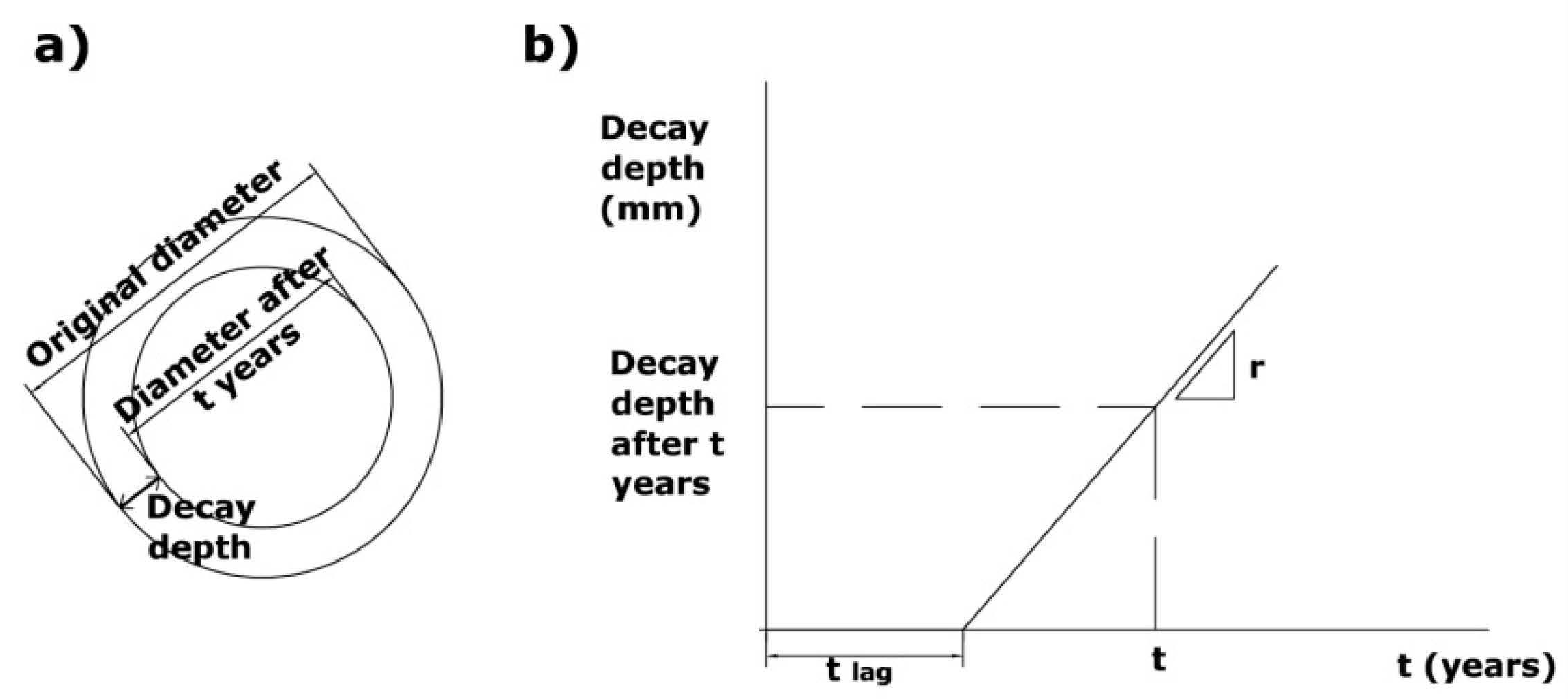
2.1. Wood Deterioration Processes

The inherent ability of wood species to resist biological deterioration is referred to as natural durability or decay resistance [22,23]. Natural durability varies between wood species [24] and is explained mainly by the composition and amount of wood extractives [22,25].
In the absence of experimental data or information from public or private institutions or organizations, a viable method to characterize the evolution of wood deterioration processes is the model of Leicester et al. [10]. Due to accumulated experience, this method yields conservative results which allow designs on the side of safety [11,17].
The Leicester et al. approach models the wood deterioration process as bi-linear [10] (Figure 1), where the untreated wood in the ground would steadily decay along the perimeter after a time lag of decay. The rate of decay (mm/year) can be calculated as:
r = k w o o d k c l i m a t e
While kclimate depends on the values of average precipitation, average annual temperature and the number of dry months on the site [10]; kwood depends on the type of wood [10]. A detailed explanation of both these coefficients and their calculation can be found in [10].
It should be noted that sapwood deteriorates more quickly than heartwood due to its higher moisture content [26]. Given the range of diameters used in SWB works (between 100 and 300 mm; [3]), the presence of juvenile wood (corewood) will be important, which also implies a greater presence of sapwood. Due to this situation, generally, the used value of the rate of decay r (mm/year) must correspond to corewood (in this way, the results will additionally err on the side of safety).
The lag time (years) (Figure 1) can be estimated in terms of the corewood decay rate (rcorewood) as shown in Equation (2) [27]:
t l a g _ c o r e w o o d = 5.5 r c o r e w o o d 0.95
According to the above model, the decay progresses inwards while the remaining wood retains the initial mechanical properties. Therefore, if at a time t the decay depth is dt (mm) (Figure 1), the bending strength can be calculated as [27]:
R = π 32 ( D 2 d t ) 3 f d
where D is the initial diameter (mm) and fd is the design strength value which is calculated by using both characteristic strength values and structural design standards [28]. Characteristic strength values of undecayed wood can be found in the literature or measured in the laboratory [29,30].
The loss of section, from the mechanical point of view, can be calculated from the estimation of the part of the radius affected by the deterioration processes.
d t = r ( t t 0 )
where: dt = depth (part of the radius) affected by deterioration processes (mm) after t years of the completion of the SWB work. The part of the diameter affected will be equal to 2dt.
A detailed explanation of the Leicester et al. [10] model parameterization process can be found in [10,27].
In the Tardio&Mickovski methodology, internal stability checks (bending and shear) take into account the diameter loss of wooden elements due to wood deterioration processes.

2.2. Reinforcement Effect Due to Root Systems

The development and use of plant root reinforcement models to assess the effects of vegetation in slope stability analysis has become a prominent research area all over the world in the last 15 years, with research developments in root anchorage models [31,32,33,34,35,36,37,38,39] and their application in practical stability problems such as shallow landslides or soil erosion [35,40,41,42,43,44].
From a mechanical point, rooted soil behavior can be simulated by using different root reinforcement models. Some of them are based on traditional limit equilibrium (LE) approaches [45]; other are based on more advanced numerical analysis [37,46]. The most common mechanical root reinforcement models are the perpendicular and inclined root reinforcement model [47,48], the fiber bundle model [31,35], the energy approach model [49], and a number of LE, finite element (FE), and finite difference (FD) numerical methods integrating the above models [37,50,51,52,53].
Plants have both beneficial and adverse effects on slope stability and are the most variable element in an SWB intervention. The way in which vegetation mechanically enhances soil mass stability is via root reinforcement. The mechanical effects of vegetation on slope stability have been extensively documented overtime [18,32,39,47]. Among the main adverse effects of vegetation are the windthrow, i.e., the loss of structural reinforcement of the slope by the roots, and the surcharge because of the vegetation weight. Models related to either plant growth or root distribution with depth are very useful for incorporating new effects in SWB techniques design because roots take the loads and distribute into soil. Small vegetation roots reinforce the soil providing and add cohesion value [54], which can be included in the Mohr–Coulomb constitutive equation [47,55,56] for soil strength.
For preliminary assessment of vegetation reinforcement, a simple breakage model (perpendicular reinforcement model; [47]) can be used assuming all roots break in tension under load. This should be used with caution because of its simplicity, reduced amount of input parameters (root area ratio at depth zRAR(z) and root tensile strength Tr; Equation (5)) and applicability [57]. It must be borne in mind that only small roots (diameter <10 mm) are considered in this model to compute the added cohesion value (cr), since big roots only contribute to slope stability as structural anchorage [58].
c r = 1.2 R A R ( z ) T r
Root system morphology and properties can be studied by field techniques [59,60,61,62] or indirectly estimated from theoretical root distribution models [6,63,64]. Published literature [65,66,67,68] includes data of root systems of the most common living material used in SWB solutions.
The distribution of roots decreases with depth under the soil surface. This distribution, expressed as root area ratio (RAR; ratio of cross section of roots and the soil cross section at depth z below ground) can be modelled using existing methods [63,64] as an exponentially decreasing function of soil depth ([64]; Equation (7), Table 1).
The mean rooting depth value (bm) predicted by the existing models [63,64], which is a third of the total depth value [63,69], is valid both at the plant community level and for water controlled ecosystems and flat areas. In this approach, the volume occupied by the roots is assumed to follow a conical distribution [64,69].
Root depths for the utilized plant species in SWB works can be determined by using allometric relations and synthetic parameters [70].
The preceding approach can be used for generating an idealized and theoretical distribution of roots with depth. This information will allow the depiction of root reinforcement magnitude variation with depth which, in turn, will be used in bioengineered slope stability analysis.
Field work campaigns for studying real root distribution should be carried out using the existing field protocols [14] to validate the assumptions and models. The thus gathered information will serve to improve the theoretical model outcomes as well for analyzing real root system typologies and depths.

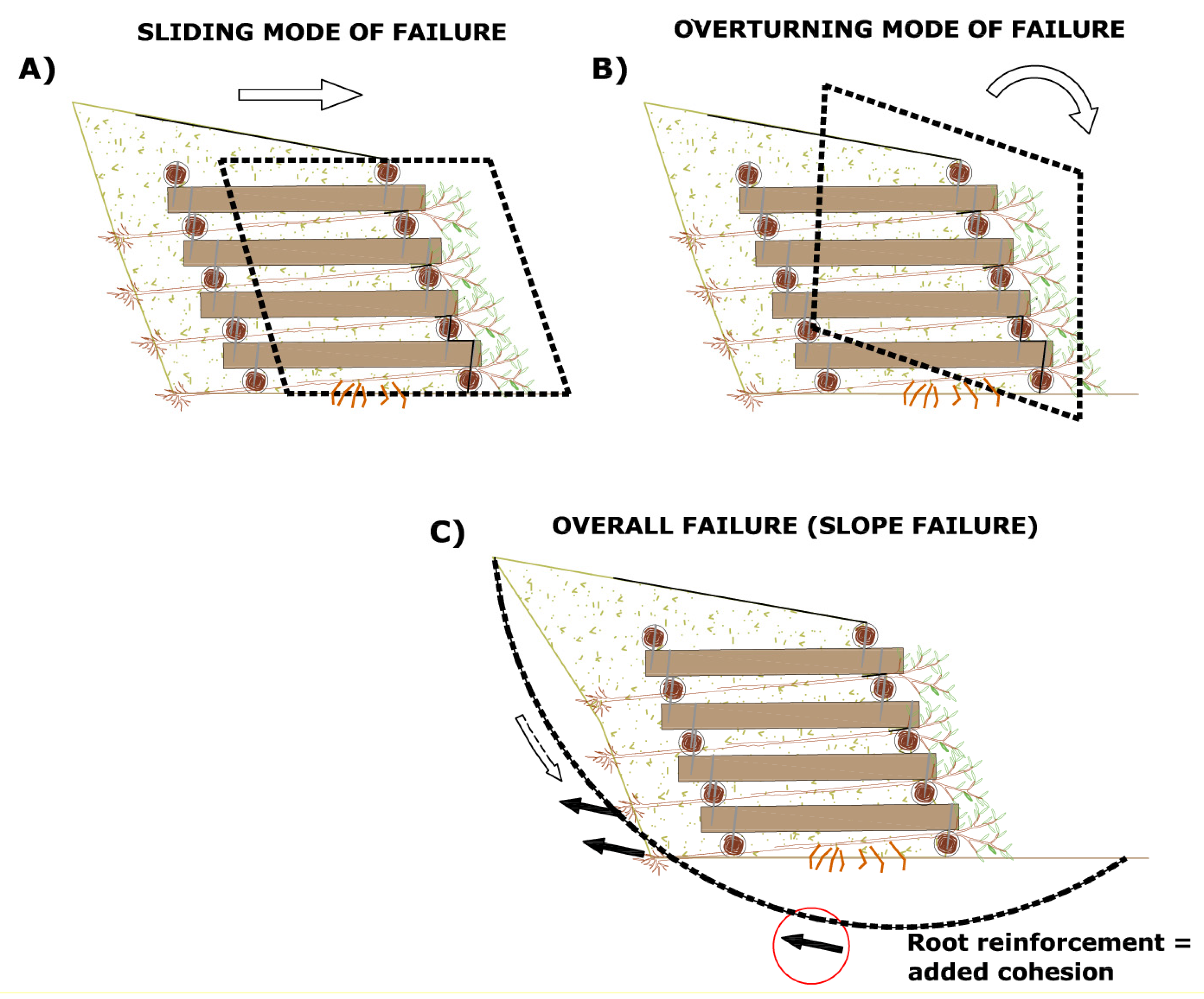
2.3. External and Internal Stability

As with any stabilization structure, SWB solutions must be checked from a structural point of view to ensure that the external (resistance to sliding and overturning, bearing capacity and slope failure; Figure 2), and internal (resistance to bending, shear, compression, tension) stability are satisfactory, and these checks must include both decay and plant effects in order to reflect the changes during the lifetime of the SWB solution. In the case of wooden elements, the internal stability calculation is based on the governing timber structural design [28]. On the other hand, the external stability checks are usually performed in line with existing geotechnical engineering design standards and the stability is expressed in terms of a Factor of Safety (FoS; [17,39]). Approaches for the estimation of the safety factors in bioengineering measures can be found in Pisano et al. [71] and Giadrossich et al. [62]. In this study, we have adopted lumped global FoS expressions for the sliding and overturning checks [50] since the purpose on this paper is to show how the different stability checks vary with time. The global stability of bioengineered slope can be assessed using existing slope stability analysis methods [20], taking into account both long-term (drained) and short-term (undrained) scenarios.

2.4. Stages and Time Milestones of the Tardio&Mickovski Methodology

A realistic methodology for designing and calculating a SWB intervention must be able to include the processes of change of the materials used (living and inert) throughout the SWB work service life [11,72]. There are three distinct stages in the overall design life of a SWB work [11,17,72]:
STAGE 1: during which the reinforcing and stabilizing functions are carried out by the inert materials (natural and/or manufactured) used in the SWB work.
STAGE 2: in which both the vegetation has already reached a good degree of development and coverage and the inert materials are still able to ensure the external and internal stability of the SWB system. There is, therefore, collaboration in the stabilizing functions between inert materials and the developing vegetation.
STAGE 3: during which vegetation is already the main stabilizing agent of the intervention area. Inert materials may continue to perform some residual reinforcing function even if they are no longer needed at this stage. The decaying wooden elements now function as a slow-release fertilizer that nourishes the developing vegetation (Figure 3).
Given the characteristics of SWB works, long-term stability can be viewed as the condition at which relatively stable plant communities are established [73], and the stabilizing contribution of the root system is well developed.
Given that the main objective of the Tardio&Mickovski methodology is ensuring the mechanical stability over the SWB service life, both the previous SWB service life stage scheme and the main elements to be taken into account at each stage can be set as follows (adapted from [17]):
STAGE 1: Time 0, just after the completion of SWB intervention. The structures of the SWB work are checked without including any reinforcing or stabilizing effect coming from the vegetation.
STAGE 2: In which a minimum time interval within which the stability of the SWB system must be ensured by the inert structures is set. The stability checks of this stage serve to ensure, in the long-term, an adequate development of the vegetation and, therefore, to give viability to the progressive transfer process of the stabilizing functions between the structures and the vegetation. At this stage, external and internal stability checks do not include any reinforcing or stabilizing effect coming from the vegetation.
The variation of the strength of wooden elements sections should be carried out according to Leicester et al. [10] and Tardio&Mickovski [17] approaches. The time milestone to be checked at this stage will be between 15 and 25 years after the SWB work completion. According to the SWB sector accumulated experience and data obtained in SWB monitoring works [14], a minimum period of 15 years is necessary for allowing an adequate vegetation development. This 15-year time milestone is based on the following works:
(a)
Sorolla et al. [74], where 23 log crib walls were analyzed. Information regarding vegetation and log crib wall deterioration processes was collected.
(b)
Castillo-Serrabasa [75], where 12 log crib walls were analyzed. Information regarding vegetation and logs deterioration processes was collected.
(c)
Case studies analyzed during the Ecomed project [14].
(d)
Bioengineering works analyzed in Wolff Kettenhuber et al. [76].
(e)
Time framework included in Fernandes and Guiomar [77].
In the abovementioned works, both the vegetation and the related ecological dynamics could be developed within a 15-year time interval (indeed this time threshold errs on the side of safety in all the preceding cases). This concrete time milestone coincides with the long-term concept defined in Walker et al. [73].
STAGE 3: This stage corresponds to the moment at which the vegetation is the main reinforcing and stabilizing element in the intervention area. In this stage, a global stability check of the SWB work is carried out at the same time milestone as STAGE 2 (at least 15 years of service life of the work), with the difference that plant roots’ reinforcing and stabilizing effects are included in the global stability check. On the other hand, no stabilizing effect coming from the inert structures is taken into account.
Figure 4 shows both the temporal structure and the stability checks to be carried out at each stage according to the Tardio&Mickovski methodology.
The above stability checks and timeline structure ensure the following:
(a)
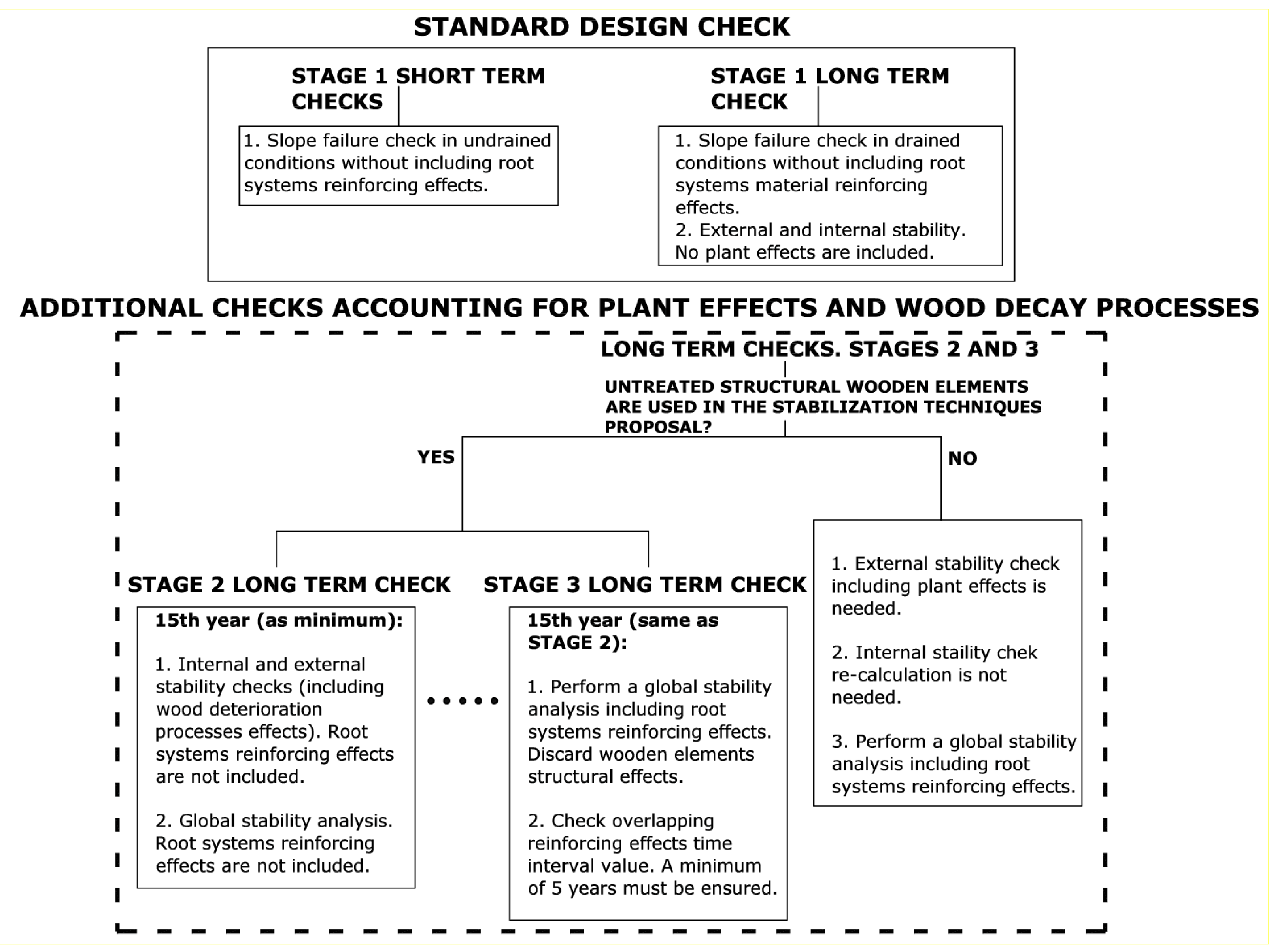
In STAGE 2, an adequate mechanical behavior is ensured for, at least, the first 15 years of the SWB work service life. This implies that the residual mechanical resistance of the bioengineered structures will always be achieved between 15 and 50 years of service life of the SWB work (depending on the species of wood used and the conditions of the intervention area). This time milestone, at which the structure will perform a residual mechanical reinforcing effect, can be calculated by using the Leicester et al. model [10].
(b)
In STAGE 3, the overall stability check is performed at the same time milestone as in STAGE 2. This ensures an overlap of time in which there is collaboration between the wooden structure (still mechanically stable in STAGE 2) and the vegetation reinforcing effects (even if this overlap of effects is not taken into account so that the design errs on the side of safety). From the STAGE 3 time milestone until the moment at which (theoretically and without taking into account plant reinforcing effects) the structure will reach its residual strength and eventually fail, there will be a time interval during which both reinforcing effects, those coming from the structure and those coming from the vegetation, will continue to overlap. A minimum value of 5 years is proposed for this extra time interval (after STAGE 3 time milestone) in which an overlapping reinforcing effect between the structures and vegetation takes place. Therefore, according to the preceding time framework, the structure’s residual strength must be reached at t = 20 years as minimum. In this way, the residual risk is minimized when adopting the SWB approach.
Therefore, the above approach ensures both the stability and collaboration between the system elements and an adequate time interval for vegetation to develop and evolve. That is, with the previous scheme of stages, time milestones and stability checks, compliance with the main objective of SWB works is ensured: in the long term, the main stabilizing and reinforcing functions are performed by vegetation.
The information needed to perform the stability checks of the SWB system at each of the before mentioned stages is shown in Table 2.
It is necessary to ensure that the inert materials (vegetal and manufactured) keep the system stable at least until STAGE 3. An extra time interval for ensuring plants and structure reinforcing effect overlap must be also ensured (a minimum value of 5 years is proposed).
To the preceding design scheme we must add maintenance and monitoring tasks accompanying and collecting information throughout the SWB service life [78]. The information collected (Figure 5) will not only serve to calibrate or correct some design aspects but will also allow better designs in future works (it will allow permanent improvement processes and adaptive information management; [78,79]).
Examples of SWB work monitoring protocols can be found and downloaded at http://ecomedbio.eu/protocols (accessed on 9 January 2023) [80].

3. Methodology Validation—Case Study

3.1. Site and SWB Work Information

An existing log crib wall in Sant Hilari Sacalm (Gerona, Spain) is analyzed. The region has a mean annual temperature of 15.5 °C, a mean annual rainfall of 749 mm and no (rainfall < 5 mm) dry months per year. This yields a kCLIMATE = 1.75 (Equation (1); [10]).
The soil strength properties include an effective cohesion of 5kPa, and effective angle of internal friction of 30°. The soil unit weight was 20.10 kN/m3 [75].
The inert wood for the SWB structure was obtained from nearby chestnut (Castanea sativa. Mill.) stands, with logs of approx. 200 mm diameter. The wood mechanical properties are the following:
Bending strength: 18 N/mm2
Shear strength: 3.4 N/mm2
The chestnut heartwood is resistant (durability class 2; AS 5604-2005). According to Leicester et al. [10], Kcorewood is twice the value of Kheartwood of the selected tree species which yields a kwood equal to 0.96 (Equation (1); [10]). For a Service Class 3 and permanent loads, the modification factor kmod = 0.5 [28]. The material coefficient γm = 1.3 and, thus, the design bending and shear strength calculated using Equations (1) and (2) will be equal to 10.77 N/mm2 and 1.38 N/mm2, respectively.
The utilized living material consists of 2.0 m length bitter willow (Salix eleagnos, Scop.) living branches (approx. diameter 10 mm) harvested from the site. Root characterization and distribution with depth was performed using theoretical models [64], plant species allometry, and synthetic parameters [70]. An average root tensile strength of 15 MPa was adopted based on published literature [81]. For the bitter willow, the allometric ratio between the plant height and the root depth was taken as 1.5 [68].
The geometry and details of the SWB structures in Sant Hilari Sacalm are shown in Figure 6 .
The log crib wall is 2.2 m high and 2.0 m wide. Given the length of the available chestnut tree logs, a bending span length of 2.0 m was adopted.
Given the terrain slope angle above the crib wall, the crib wall inclination and the preceding data, the active thrust coefficient (ka; Coulomb theory) equals to 0.335.
In this case study example, the log crib wall design both in the short and long term using the Tardio&Mickovski methodology was checked and justified. This included performing the stability checks of the methodology work service life stages as shown in Table 2.
Castillo-Serrabasa [75] analyzed the log crib wall in Sant Hilari Sacalm and carried out different monitoring tasks. Therefore, existing information regarding the wood deterioration processes and the vegetation dynamics in the case study area was used. The Tardio&Mickovski methodology implementation and outcomes were then compared with the collected information in the preceding SWB monitoring tasks.

3.2. STAGE 1: Stability Checks

The internal stability check was performed for the ‘in-ground condition’-critical situation where the wooden elements (logs) are buried (Figure 7). For the internal stability check, the bending and shear strength analyses were performed according to Eurocode 5 [28]. The outer log row is considered as the most critical from both durability and bending stress aspects [82] because of its exposure to the climate and loading. The inner row of logs will be subjected to both a lower temperature and moisture variation throughout the year and, at that depth, the level of oxygen will be lower and, therefore, the biotic activity will be lower [76]. Finally, from a bending analysis point of view, the outer row does not have soil in front counteracting the soil thrust, unlike the inner row.
In STAGE 1 wood deterioration processes are not active and vegetation reinforcement effects are not taken into account.
The results obtained are presented in Table 3:
Therefore, in STAGE 1, the crib wall is mechanically stable.

3.3. STAGE 2: Analysis of Wood Deterioration Processes

For the stability checks included in the Tardio&Mickovski methodology STAGE 2, it is necessary to estimate the progress of wood deterioration processes. According to the case study information, a decay rate (r) of 1.68 mm/year is obtained (Equation (1); [10]).
As stated before, a time milestone equal to 15 years (after the work completion) is analyzed.
On the other hand, the lag time (tL; number of years until wood deterioration processes are activated) is 3.36 years (Equation (2); [10]). Therefore, the part of the radius affected by the deterioration processes after 15 years of service life was calculated as dt = 19.53 mm (Equation (4); [10]). The effective diameter (diameter not affected by deterioration processes) after 15 years was calculated to be 16 cm.
According to Leicester et al. [10] model and the log crib wall internal stability analysis, the number of years for reaching the log crib wall residual mechanical resistance is 28. For this, the minimum diameter necessary to withstand existing loads and forces is calculated. After that, the number of years for reaching that diameter value (by including the deterioration processes effects) is determined.

3.4. STAGE 2: Stability Checks

Using the above data and according to the Tardio&Mickovski methodology, in STAGE 2, the log crib wall internal stability check is carried out, taking into account wood deterioration effects. In this stage, the reinforcing effects of vegetation are not included. As stated before, the objective is ensuring a minimum time interval of 15 years for allowing an adequate development of vegetation.
In the new situation, the results obtained are as follows (Table 4):
Therefore, in STAGE2, the crib wall is mechanically stable. The log crib wall is able to stabilize the intervention area, allowing vegetation to develop and fulfill its reinforcing functions.

3.5. STAGE 3: Stability Checks

The vegetation characterization included in Castillo-Serrabasa (2022) [75] offers the following information:
(a)
Mean vegetation height = 3.5 m
(b)
Mean vegetation diameter = 0.12 m
According to the preceding information, and taking into account the bitter willow allometry, a total root system depth of 2.3 m is estimated. According to Preti et al. [64] and Gonzalez-Ollauri and Mickovski [69], a mean rooting depth (bm) of 0.78 m is obtained. Following Preti et al. [58], a RAR value of 0.0008 is obtained at z = 2.0 m. This depth has been chosen for defining the root reinforced area within the log crib wall geometry.
According to Wu’s [47] model (Equation (5)), the additional cohesion due to roots equals to 7.83 kPa. This value has been added to the bare soil cohesion value for performing an overall stability analysis of the bioengineered slope. The mechanical reinforcing effects of the log crib wall are discarded in this stage of the methodology.
A global stability factor of 1.7 is obtained for the slope supported by the vegetated log crib wall. Therefore, the global stability is now ensured by the vegetation. Furthermore, given that the log crib wall is stable up to the 28th year of the SWB service life, there is an extra time interval of 13 years where the reinforcing and stabilizing effects of both the SWB structures and the vegetation are overlapping.

4. Discussion

In the SWB approach, the use of materials which change their properties with time (plants and wood) is very common, and a design methodology which makes an allowance for the deterioration and change of the work will be a very useful tool for eco-engineers. Indeed, the proposed methodology allows the interconnection between the SWB work evolution and the engineering work design stage.
From the comparison of STAGE 1 and STAGE 2 safety factors values, it can be noted that STAGE 2 sliding and overturning safety factors are slightly lower compared to the results obtained in STAGE 1. This is mainly due to log crib wall loss of weight because of the wood deterioration processes and the log diameter losses. In fact, this situation is counter balanced by the developing vegetation weight (which could be included as an overburden load over the SBW structure) [81] but, as stated before, all the effects coming from the vegetation are not taken into account in STAGE 2 of the methodology.
On the other hand, the methodology proposed here has proven that, for the case study conditions, the selected log crib wall minimum diameter (0.2 m) allows for an adequate performance of the SWB work throughout its entire service life. With the selected log crib wall structure, the viability of the stress transfer processes between the SWB structure and the vegetation is ensured (as was confirmed in the SBW monitoring works in Sant Hilari Sacalm). Indeed, as proved in STAGE 3 stability checks, the long-term slope global stability is ensured by the vegetation.
For parametrization purposes, the methodology has been applied to the same crib wall but changing the wood type of the logs. In this new exercise, a wood type with lower natural durability has been chosen. Particularly, the crib wall will have logs of 0.2 m diameter of Pinus uncinate Mill. The results obtained are shown in Table 5.
Therefore, the log crib wall made of pine wood is shown to be mechanically unstable in the long-term. According to Table 5, design decisions must be taken in order to ensure the SWB long term stability. In this case, both a reduction of the bending span length and an increase of log diameters are adopted. In particular, the bending span length is reduced by up to 1.5 m and the diameters are increased up to 0.25 m. With these new values, STAGE 2 stability checks are positively verified. Furthermore, the residual strength resistance of the new crib wall will be reached at t = 26 years. Therefore, the overlapping effects between the SBW structure and the vegetation are developed during an extra time interval of 11 years (after the STAGE 3 time milestone).
Thus, the proposed methodology is able to detect design scenarios where the structure would be unstable without giving enough time to the vegetation to properly settle down and reinforce the slope. Traditional design would not have detected this situation and therefore an improvement within the design stage of SWB works has been proven.
Comparisons with existing SWB monitoring outcomes:
In Castillo-Serrabasa [75], the state of deterioration of the crib walls was classified according to five different levels:
LEVEL 1: Intact structure
LEVEL 2: The onset of deterioration processes is detected. Structural integrity remains intact.
LEVEL 3: Sapwood already deteriorated. The onset of corewood and heartwood deterioration processes is detected.
LEVEL 4: The structure shows zones with an overall and clear deformation. Structural mechanical integrity is clearly reduced. Corewood deterioration processes are clear.
LEVEL 5: The structure fulfills only a residual mechanical function. Some parts of the crib wall logs are totally deteriorated. Roots and soil occupy parts of the original structure.
According to the 12 log crib walls analyzed in Castillo-Serrabasa [69], a mean value of 7 years is necessary to pass from one level of deterioration to the next one. The regression line obtained in that study is the following:
y = 0.1234 x + 1.4091
where y is the deterioration level and x is the number of years.
Therefore, according to Equation (8), a total of 28 years is necessary for going through all the deterioration levels defined in Castillo-Serrabasa [75]. This outcome coincides with that obtained in the Tardio&Mickovski methodology, in which it was concluded that the log crib wall would reach its residual strength after 28 years of work service life. This result is also in good agreement with existing research papers regarding SWB structure evolution [72,84]. Furthermore, the structure stability was verified at t = 15 years and this is in good agreement with field work observations. Therefore, the outcomes of the proposed methodology are in good agreement with the field work data collected in SWB monitoring works.
All the obtained results err on the safe side when compared with existing SWB field work monitoring outcomes and existing research papers [72,84].

5. Conclusions

The dynamic nature of bioengineering works must be reflected and incorporated into the design methodologies of this type of intervention because of the potential instability of either the structure or the slope that is being stabilized. Factors such as the deterioration processes of the biodegradable materials used and the evolution of the vegetation reinforcement effects should be integrated into the calculation of this type of work. This approach is aligned with the “quantitative soil bioengineering” concept [85].
Although there are protocols and methods for both assessing SWB structure stability and plant root reinforcement effects, they have not been utilized for either organizing or structuring an overall design framework reflecting the SWB service life dynamic and performance. The existing methods have been utilized for assessing a concrete moment of a SWB work but a time staged scheme and approach for SWB work design was lacking.
The proposed methodology covers an existing gap in the SWB works design. It not only complements existing support decision frameworks for SWB technique selection [11] but also contributes to the SWB technique calculation all over the SWB service life stages in a comprehensive fashion. Existing SWB design protocols [83] only cover the end of construction stability checks, giving place to an unrealistic design framework for this type of intervention.
The proposed methodology (Tardio&Mickovski methodology) collects the SWB structure critical points from the lifetime of the structure and ensures an effective development and transfer of the stabilizing functions between the inert elements and the utilized living material in the long-term. This methodology also reflects the evolution of the stabilizing role of vegetation and the stress transfer phenomena involved in a typical SWB intervention. The Tardio&Mickovski methodology allows for the detection, anticipation, and solving of critical issues during the service life of the bioengineering work as well as supporting the SWB design decision making process. This capacity is especially relevant in this type of works since the main objective is to ensure the correct development of the living plants used as well as their reinforcement and stabilization functions [18]. Ensuring stability over the SWB service life creates the possibility of ecological dynamics development and ecological succession phenomena [73,86,87].
It is worth mentioning that, to the above purely mechanical objective, we must add all the ecological and ecosystem benefits obtained in parallel. Indeed, a comprehensive and fair assessment of nature-based solutions (NBS) and SWB techniques must include all benefits and effects achieved throughout the service life of the intervention [8]. Parameters such as biodiversity increase check, resilience evolution check, sustainability check, etc. could be included in a future expanded version of the proposed methodology, together with an opportunity to map the spatio-temporal development of the solution [88].
The proposed methodology enables the generation of continuous improvement processes (adaptive management of information), the calibration of the method, and the use of the information generated during the monitoring stage of SWB works.
The proposed methodology has been successfully utilized in nature restoration projects for local, regional, and national public administrations in Spain (e.g., projects for the Hydrological Confederation of the Tajo river, projects for Naturalea, Ltd., Castellar del Vallès, Spain). It is also being included in technical manuals and tutorials for regional public Spanish administrations (e.g., Diputación Foral de Bizkaia).
The accumulation of SWB monitoring data, together with the data surveyed on sites [89], will be a remarkable source of useful information both to calibrate the proposed methodology and to gather data regarding wood decay, root morphology, and plant evolution.

Author Contributions

Both authors (G.T. and S.B.M.) have equally contributed to the writing of this study. All authors have read and agreed to the published version of the manuscript.

Funding

This research received no external funding.

Institutional Review Board Statement

Not applicable.

Informed Consent Statement

Not applicable.

Data Availability Statement

Restrictions apply to the availability of these data. Data were obtained from Naturalea Ltd. and are available from the authors with the permission of Naturalea Ltd.

Acknowledgments

The authors would like to thank Naturalea Ltd. for providing field work data of their SWB monitoring works.

Conflicts of Interest

The authors declare that they have no known competing financial interests or personal relationships that could have appeared to influence the work reported in this paper.

References

  1. Schiechtl, H.M. Bioengineering for Land Reclamation and Conservation; Univ. of Alberta Press: Edmonton, AB, Canada, 1980. [Google Scholar]
  2. EFIB. European Guidelines for Soil and Water Bioengineering. European Federation for Soil and Water Bioengineering, 2015. Available online: https://boku.ac.at/baunat/iblb/efib-european-federation-of-soil-bioengineering (accessed on 4 February 2020).
  3. Schiechtl, H.M.; Stern, R. Ground Bioengineering Techniques: For Slope Protection and Erosion Control; Wiley-Blackwell: Hoboken, NJ, USA, 1996; ISBN 10: 0632040610/13: 9780632040612. [Google Scholar]
  4. Seddon, N.; Smith, A.; Smith, P.; Key, I.; Chausson, A.; Girardin, C.; Turner, B. Getting the message right on nature-based solutions to climate change. Glob. Change Biol. 2021, 27, 1518–1546. [Google Scholar] [CrossRef] [PubMed]
  5. EU. Communication from the Commission to the European Parliament, the Council, the European Economic and Social Committee and the Committee of the Regions Green Infrastructure (GI)—Enhancing Europe’s Natural Capital, /* COM/ 2013/0249 final */. 2013. Available online: https://eur-lex.europa.eu/legal-content/EN/TXT/?uri=CELEX:52013DC0249 (accessed on 9 January 2023).
  6. Preti, F.; Dani, A.; Noto, L.V.; Arnone, E. On the Leonardo’s rule for the assessment of root profile. Ecol. Eng. 2022, 179, 106620. [Google Scholar] [CrossRef]
  7. Debele, S.E.; Kumar, P.; Sahani, J.; Marti-Cardona, B.; Mickovski, S.B.; Leo, L.S.; Porcù, F.; Bertini, F.; Montesi, D.; Vojinovic, Z.; et al. Nature-based solutions for hydro-meteorological hazards: Revised concepts, classification schemes and databases. Environ. Res. 2019, 179 Pt B, 108799. [Google Scholar] [CrossRef]
  8. Mickovski, S.B.; Gonzalez-Ollauri, A.; Thomson, C.S.; Gallagher, C.E.; Tardio, G. Assessment of the Sustainability Performance of Eco-Engineering Measures in the Mediterranean Region. Land 2022, 11, 533. [Google Scholar] [CrossRef]
  9. Bischetti, G.B.; Chiaradia, E.A.; D’Agostino, V.; Simonato, T. Quantifying the effect of brush layering on slope stability. Ecol. Eng. 2009, 36, 258–264. [Google Scholar] [CrossRef]
  10. Leicester, R.H.; Wang, C.-H.; Ngyen, M.N.; Thornton, J.D.; Johnson, G.; Gardner, D.; Foliente, G.C.; Mackenzie, C. An Engineering Model for the Decay in Wood in Ground Contact; Document No IRGWP 03-20260; International Research Group on Wood Protection: Stockholm, Sweden, 2003. [Google Scholar]
  11. Bischetti, G.B.; De Cesare, G.; Mickovski, S.B.; Rauch, H.P.; Schwarz, M.; Stangl, R. Design and temporal issues in Soil Bioengineering structures for the stabilisation of shallow soil movements. Ecol. Eng. 2021, 169, 106309. [Google Scholar] [CrossRef]
  12. Gonzalez Ollauri, A.; Mickovski, S.B.; Anderson, C.; Debele, S.; Emmanuel, R.; Kumar, P.; Loupis, M.; Ommer, J.; Pfeiffer, J.; Panga, D.; et al. A Nature-based solution selection framework: Criteria and processes for addressing hydro-meteorological hazards at open-air laboratories across Europe. J. Environ. Manag. 2023, 331, 117183. [Google Scholar] [CrossRef]
  13. Kumar, P.; Debele, S.E.; Sahani, J.; Rawat, N.; Marti-Cardona, B.; Alfieri, S.M.; Basu, B.; Basu, A.S.; Bowyer, P.; Charizopoulos, N.; et al. Nature-based solutions efficiency evaluation against natural hazards: Modelling methods, advantages and limitations. Sci. Total Environ. 2021, 784, 147058. [Google Scholar] [CrossRef]
  14. García-Rodríguez, J.L.; Sangalli, P.; Tardio, G.; Mickovski, S.; Fernandes, J.; Gimenez, M. (Eds.) Specialization Process for the Bioengineering Sector in the Mediterranean Environment. ECOMED Project; Part II. Protocols and Case Studies; Fundación Conde del Valle de Salazar: Madrid, Spain, 2019; ISBN 978-84-96442-89-4. [Google Scholar]
  15. Kumar, P.; Debele, S.E.; Sahani, J.; Rawat, N.; Marti-Cardona, B.; Alfieri, S.M.; Basu, B.; Basu, A.S.; Bowyer, P.; Charizopoulos, N.; et al. An overview of monitoring methods for assessing the performance of nature-based solutions against natural hazards. Earth Sci. Rev. 2021, 217, 103603. [Google Scholar] [CrossRef]
  16. Rey, F.; Bifulco, C.; Bischetti, G.B.; Bourrier, F.; De Cesare, G.; Florineth, F.; Graf, F.; Marden, M.; Mickovski, S.B.; Phillips, C.; et al. Soil and water bioengineering: Practice and research needs for reconciling natural hazard control and ecological restoration. Sci. Total Environ. 2019, 648, 1210–1218. [Google Scholar] [CrossRef]
  17. Tardio, G.; Mickovski, S.B. Implementation of eco-engineering design into existing slope stability design practices. J. Ecol. Eng. 2016, 92, 138–147. [Google Scholar] [CrossRef]
  18. Stokes, A.; Douglas, G.B.; Fourcaud, T.; Giadrossich, F.; Gillies, C.; Hubble, T.; Kim, J.H.; Loades, K.W.; Mao, Z.; McIvor, I.R.; et al. Ecological mitigation of hillslope instability: Ten key issues facing researchers and practitioners. Plant Soil 2014, 377, 1–23. [Google Scholar] [CrossRef]
  19. Mickovski, S. Resilient design of landslip prevention measures: A case study. Proc. ICE—Forensic Eng. 2015, 168, 96–106. [Google Scholar] [CrossRef]
  20. Duncan, J.M.; Wright, S.G. Soil Strength and Slope Stability; John Wiley and Sons, Inc.: Hoboken, NJ, USA, 2005. [Google Scholar]
  21. Roque, A.J.; Paleologos, E.K.; O’Kelly, B.C.; Tang, A.M.; Reddy, K.R.; Vitone, C.; Mohamed, A.M.O.; Koda, E.; Goli, V.S.N.S.; Vieira, C.S.; et al. Sustainable environmental geotechnics practices for a green econom. Environ. Geotech. 2022, 9, 68–84. [Google Scholar] [CrossRef]
  22. Eaton, R.A.; Hale, M.D.C. Natural durability. In Wood Decay, Pests and Protection, 1st ed.; Chapman & Hall: London, UK, 1993; pp. 311–318. [Google Scholar]
  23. Johnson, G.C.; Thornton, J.D.; Trajstman, A.C.; Cookson, L.J. Comparative in-ground natural durability of white and black cypress pines (Callitris glaucophylla and C. endlicheri). Aust. For. 2006, 69, 243–247. [Google Scholar] [CrossRef]
  24. UNE-EN 350; Durability of Wood and Wood-Based Products—Testing and Classification of the Durability to Biological Agents of Wood and Wood-Based Materials. European Committee for Standardisation (CEN): Brussels, Belgium, 2016.
  25. Niklewski, J.; van Niekerk, P.B.; Brischke, C.; Frühwald Hansson, E. Evaluation of Moisture and Decay Models for a New Design Framework for Decay Prediction of Wood. Forests 2021, 12, 721. [Google Scholar] [CrossRef]
  26. Boddy, L.; Rayner, A.D.M. Origins of decay in living deciduous trees: The role of the moisture content and re-appraisal of the expanded concept of tree decay. New Phytol. 1983, 94, 623–641. [Google Scholar] [CrossRef]
  27. Wang, C.H.; Leicester, R.H.; Foliente, G.C.; Nguyen, M.N. Wood Service Life Design Guide; Forest and Wood Products Australia Limited: Melbourne, Australia, 2007; 115p. [Google Scholar]
  28. EN 1995-1-1:2004/A1:2008; Eurocode 5: Design of Timber Structures—Part 1-1: General—Common Rules and Rules for Buildings/Incl Amendment A1. European Committee for Standardization: Brussels, Belgium, 2008.
  29. De Vries, P.A. Quality and Strength Characterisation of Small Diameter Larch (Larix kaempferi (LMAB.) CARRR.); Report C4-98-01; Delft University: Delft, The Netherlands, 1998. [Google Scholar]
  30. Ranta-Maunus, A.; Saarelainen, U.; Boren, H. Strength of small-diameter round wood. In Proceedings of the CIB W18 Meeting in Savonlinna, Savonlinna, Finland, 12–14 August 1998. Paper 31-6-3, 10p. [Google Scholar]
  31. Pollen, N.; Simon, A. Estimating the mechanical effects of riparian vegetation on stream bank stability using a fiber bundle model. Water Resour. Res. 2005, 41, W07025. [Google Scholar] [CrossRef]
  32. Norris, J.E.; Stokes, A.; Mickovski, S.B.; Cammeraat, E.; Van Beek, R.; Nicoll, B.C.; Achim, A. (Eds.) Slope Stability and Erosion Control: Ecotechnological Solutions; Springer: Berlin/Heidelberg, Germany, 2008; Volume VI, 290p. [Google Scholar]
  33. Stokes, A.; Atger, C.; Bengough, A.; Fourcaud, T.; Sidle, R. Desirable plant root traits for protecting natural and engineered slopes against landslides. Plant Soil. 2009, 324, 1–30. [Google Scholar] [CrossRef]
  34. Preti, F.; Giadrossich, F. Root reinforcement and bioengineering stabilisation by Spanish broom. Hydrol. Earth Syst. Sci. 2009, 13, 1713–1726. [Google Scholar] [CrossRef]
  35. Schwarz, M.; Cohen, D.; Or, D. Root–soil mechanical interactions during pullout and failure of root bundles. J. Geophys. Res. Atmos. 2010, 115. [Google Scholar] [CrossRef]
  36. Fan, C.C. A displacement-based model for estimating the shear resistance of root-permeated soils. Plant Soil 2012, 355, 103–119. [Google Scholar] [CrossRef]
  37. Bourrier, F.; Kneib, F.; Chareyre, B.; Fourcaud, T. Discrete modelling of granular soils reinforcement by plant roots. Ecol. Eng. 2013, 61 Pt C, 646–657. [Google Scholar] [CrossRef]
  38. Schwarz, M.; Cohen, D.; Giadrossich, F. Quantification of Compressed rooted soil. JGR Earth Surf. 2015, 120, 2103–2120. [Google Scholar] [CrossRef]
  39. Tardio, G.; Mickovski, S.B. Method for synchronisation of soil and root behaviour for assessment of stability of vegetated slopes. J. Ecol. Eng. 2015, 82, 222–230. [Google Scholar] [CrossRef]
  40. Coppin, N.J.; Richards, I.G. Use of Vegetation in Civil Engineering; CIRIA Butterworths Construction Industry Research and Information Association: London, UK, 2007. [Google Scholar]
  41. Danjon, F.; Barker, D.H.; Drexhage, M.; Stokes, A. Using three dimensional plant root architecture in models of shallow-slope stability. Ann. Bot. 2007, 101, 1281–1293. [Google Scholar] [CrossRef] [PubMed]
  42. Mickovski, S.B.; van Beek, L.P.H.; Salin, F. Uprooting resistance of vetiver grass (Vetiveria zizanioides). Plant Soil 2005, 278, 33–41. [Google Scholar] [CrossRef]
  43. Thomas, R.E.; Pollen-Bankhead, N. Modelling root reinforcement with a fibre-bundle model and Monte Carlo simulation. Ecol. Eng. 2010, 36, 47–61. [Google Scholar] [CrossRef]
  44. Gonzalez-Ollauri, A.; Mickovski, S.B. The effect of willow (Salix sp.) on soil moisture and matric suction at a slope scale. Sustainability 2020, 12, 9789. [Google Scholar] [CrossRef]
  45. Greenwood, J.R. SLIP4EX—A program for routine slope stability analysis to include the effects of vegetation, reinforcement and hydrological changes. J. Geotech. Geol. Eng. 2006, 24, 449–465. [Google Scholar] [CrossRef]
  46. Dupuy, L.; Fourcaud, T.; Lac, P.; Stokes, A. A generic 3d finite element model of tree anchorage integrating soil mechanics and real root system architecture. Am. J. Bot. 2007, 94, 1506–1514. [Google Scholar] [CrossRef] [PubMed]
  47. Wu, T.H. Investigation of landslides on Prince of Wales Island. Geotechnical Engineering Report 5; Civil Engineering Department, Ohio State University: Columbus, OH, USA, 1976. [Google Scholar]
  48. Gray, D.H.; Leiser, A.T. Biotechnical Slope Protection and Erosion Control; Van Nostrand Reinhold: New York, NY, USA, 1982. [Google Scholar]
  49. Ekanayake, J.C.; Marden, M.; Watson, A.J.; Rowa, D. Tree roots and slope stability: A comparison between Pinus radiata and kanuka. N. Z. J. For. Sci. 1997, 27, 216–233. [Google Scholar]
  50. Gray, D.H.; Sotir, R.B. Biotechnical and Eco-Engineering Slope Stabilization; Wiley: New York, NY, USA, 1996; p. 276. [Google Scholar]
  51. Chok, Y.H.; Kaggwa, W.S.; Jaksa, M.B.; Griffiths, D.V. Modelling the effects of vegetation on the stability of slopes. In Proceedings of the 9th Australia New Zealand Conference on Geomechanics, Auckland, New Zealand, 8–11 February 2004. [Google Scholar]
  52. Fourcaud, T.; Ji, J.N.; Zhang, Z.Q.; Stokes, A. Understanding the impact of root morphology on overturning mechanisms: A modelling approach. Ann. Bot. 2007, 101, 1267–1280. [Google Scholar] [CrossRef]
  53. Mickovski, S.B.; Stokes, A.; van Beek, L.P.H.; Ghestem, M.; Fourcaud, T. Simulation of direct shear tests on rooted and non-rooted soil using Finite Element analysis. Ecol. Eng. 2011, 37, 1523–1532. [Google Scholar] [CrossRef]
  54. Waldron, L.J. Shear resistance of root-permeated homogenous and stratified soil. Soil Sci. Soc. Am. J. 1977, 41, 843–849. [Google Scholar] [CrossRef]
  55. Ekanayake, J.; Phillips, C. Slope stability thresholds for vegetated hillslopes: A composite model. Can. Geotech. J. 2002, 39, 849–862. [Google Scholar] [CrossRef]
  56. Stokes, A.; Norris, J.E.; Van Beek, L.P.H.; Bogaard, T.; Cammeraat, E.; Mickovski, S.B.; Jenner, A.; Di Iorio, A.; Fourcaud, T. How vegetation reinforces soil on slopes. In Slope Stability and Erosion Control: Ecotechnological Solutions; Norris, J., Stokes, A., Mickovski, S., Cammeraat, E., Van Beek, R., Nicoll, B., Achim, A., Eds.; Springer: Dordrecht, The Netherlands, 2008; pp. 65–116. [Google Scholar]
  57. Mickovski, S.B.; Hallett, P.D.; Bengough, A.G.; Bransby, M.F.; Davies, M.C.R.; Sonnenberg, R. The effect of willow roots on the shear strength of soil. In Advances in GeoEcology 39: The Soils of Tomorrow, Proceedings of the 5th International Congress of the European Society for Soil Conservation, Palermo, Italy, 25–30 June 2007; Dazzi, C., Constantini, E., Eds.; Catena Verlag Gmbh: Reiskirchen, Germany, 2008; pp. 247–262. [Google Scholar]
  58. Mickovski, S.; Hallet, P.; Bransby, M.; Davis, M.; Sonnenberg, R.; Bengough, A. Mechanical reinforcement of soil by willow roots: Impacts of root properties and root failure mechanism. Soil Sci. Am. Soc. Agron. 2009, 73, 1276–1285. [Google Scholar] [CrossRef]
  59. Böhm, W. Methods of Studying Root Systems; Springer: Berlin/Heidelberg, Germany, 1979; p. 275. [Google Scholar]
  60. Van Noordwijk, M.; Brouwer, G.; Meijbroom, F.; Oliveira, M.R.G.; Bengough, A.G. Trench profile techniques and core break methods. In Root Methods: A Handbook; Smit, A.L., Ed.; Springer: Berlin/Heidelberg, Germany, 2000; pp. 211–233. [Google Scholar]
  61. Tardio, G.; González-Ollauri, A.; Mickovski, S.B. A non-invasive preferential root distribution analysis methodology from a slope stability approach. J. Ecol. Eng. 2016, 97, 46–57. [Google Scholar] [CrossRef]
  62. Giadrossich, F.; Schwarz, M.; Marden, M.; Marrosu, R.; Phillips, C. Bio-engineering traits of Pinus radiata D.Don: A case study in New Zealand. N. Z. J. For. Sci. 2020, 50, 17854. [Google Scholar] [CrossRef]
  63. Laio, F.; D’odorico, P.; Ridolfi, L. An analytical model to relate the vertical root distribution to climate and soil properties. Geophys. Res. Lett. 2006, 33, L18401. [Google Scholar] [CrossRef]
  64. Preti, F.; Dani, A.; Laio, F. Root profile assessment by means of hydrological, pedological and above-ground vegetation information for bio-engineering purposes. Ecol. Eng. 2010, 36, 305–316. [Google Scholar] [CrossRef]
  65. Francis, R.A.; Gurnell, A.M.; Petts, G.E.; Edwards, P.J. Survival and growth responses of Populus nigra, Salix elaeagnos and Alnus icana cuttings to varying levels of hydric stress. For. Ecol. Manag. 2005, 210, 291–301. [Google Scholar] [CrossRef]
  66. Schenk, H.J.; Jackson, R.B. Rooting depths, lateral root spreads and below-ground/above-ground allometries of plants in water-limited ecosystems. J. Ecol. 2002, 90, 480–494. [Google Scholar] [CrossRef]
  67. Waisel, Y.; Eshel, A.; Kafkafy, U. Plant Roots: The Hidden Half, 3rd ed.; Mercel Dekker Inc.: New York, NY, USA, 2002. [Google Scholar]
  68. Kutschera, L.; Lichtenegger, E. Wurzelatlas Mitteleuropäischer Waldbäume und Sträucher; Leopold Stocker Verlag: Graz, Austria; Stuttgart, Germany, 2002; 604p. [Google Scholar]
  69. Gonzalez-Ollauri, A.; Mickovski, S.B. Using the root spread information of pioneer plants to quantify their mitigation potential against shallow landslides and erosion intemperate humid climates. Ecol. Eng. 2016, 95, 302–315. [Google Scholar] [CrossRef]
  70. Cornelini, P.; Federico, C.; Pirrera, G. Arbusti Autoctoni Mediterranei per L’ingegneria Naturalistica. Primo Contributo Alla Morfometria Degli Apparati Radicali; n. 48; Azienda Regionale Foreste Demaniali Regione Siciliana, Collana Sicilia Foreste: Palermo, Italy, 2008. [Google Scholar]
  71. Pisano, M.; Cardile, G.; Ricciardi, A. Deterministic and probabilistic analyses of slopes reinforced with vegetation. In Geotechnical Research for Land Protection and Development; Lecture Notes in Civil Engineering, 40, Calvetti, F., Cotecchia, F., Galli, A., Jommi, C., Eds.; CNRIG, 2019; Springer: Cham, Switzerland, 2020. [Google Scholar]
  72. Schwarz, M. Wirkung der Vegetation in Biologischen Maßnahmen. In Stabilisierung Rutschender Hänge. FOBATEC Tagungsskript; Krättli, W., Schwarz, M., Eds.; Fachstelle Für Forstliche Bautechnik: Maienfeld, Switzerland, 2015; Available online: http://www.fobatec.ch/fileadmin/user_upload/customers/fobatec/09Unterlagen/Tagungsunterlagen/TagungsskriptRutschung151021.pdf (accessed on 9 January 2023).
  73. Walker, L.R.; Velázquez, E.; Shiels, A.B. Applying lessons from ecological succession to the restoration of landslides. Plant Soil 2009, 324, 157–161. [Google Scholar] [CrossRef]
  74. Sorolla, A.; Piera, E.; Mota- Freixas, B.; Sorolla Salvans, G.; Rueda, I.; Lochner Prats, A.; Unzeta, C. Improvement of the Plantation Success in a Crib Wall in a Mediterranean Hydro-Meteorological Risks Scenario—Practical Results. Sustainability 2021, 13, 11785. [Google Scholar] [CrossRef]
  75. Castillo-Serrabasa, J. Avaluació Funcional i Estructural Dels Entramats en AmbientsFluvials. Treball de Final de Máster. Master D’ecologia, Gestió i Restauració del Medi Natural; Facultat de Biologia, Universitat de Barcelona: Barcelona, Spain, 2022. [Google Scholar]
  76. Wolff Kettenhuber, P.L.W.; dos Santos Sousa RJoel Dewes, J.; Rauch, H.P.; Sutili, F.J.; Hörbinger, S. Performance assessment of a soil and water bioengineering work on the basis of the flora development and its associated ecosystem processes. Ecol. Eng. 2023, 186, 106840. [Google Scholar] [CrossRef]
  77. Fernandes, J.P.; Guiomar, N. Simulating the stabilization effect of soil bioengineering interventionsin Mediterranean environments using limit equilibrium stability models and combinations of plant species. Ecol. Eng. 2016, 88, 122–142. [Google Scholar] [CrossRef]
  78. Tardio, G.; Mickovski, S.B.; Sangalli, P. Incorporating the particularities of soil and water bioengineering works into a design methodology with monitoring feedback loops. In Proceedings of the Seventh International Conference on Structural Engineering, Mechanics and Computation (SMEC), Cape Town, South Africa, 2–4 September 2019. [Google Scholar]
  79. Mickovski, S.B. Re-Thinking Soil Bioengineering to Address Climate Change Challenges. Sustainability 2021, 13, 3338. [Google Scholar] [CrossRef]
  80. Zaimes, G.N.; Tardio, G.; Iakovoglou, V.; Gimenez, M.; Garcia-Rodriguez, J.L. New tools and approaches to promote soil and water bioengineering in the Mediterranean. Sci. Total Environ. 2019, 693, 133677. [Google Scholar] [CrossRef]
  81. Sauli, G.; Cornelini, P.; Preti, F. Manuale di Ingegneria Naturalistica; Sistemazione dei Versanti; Regione Lazio: Rome, Italy, 2005; Volume 3. [Google Scholar]
  82. Stangl, R.; Tesarz, M. Wirksamkeit von Bepflanzten Holzkrainerwänden als Ingenieurbiologische Hangsicherungsmassnahmen; Universität für Bodenkultur: Wien, Austria, 2003. [Google Scholar]
  83. Menegazzi, G.; Palmeri, F. Il Dimensionamento Delle Opere di Ingegneria Naturalistica; Direzione Infrastrutture, Ambiente e Politiche Abitative: Regione Lazio, Italy, 2013. [Google Scholar]
  84. Böll, A.; Burri, K.; Gerber, W.; Graf, F. Long-term studies of joint technical and biological measures. For. Snow Landsc. Res. 2009, 82, 9–32. [Google Scholar]
  85. Schwarz, M. Wurzelverst¨arkung und Hangstabilit¨atsberechnungen: Eine Übersicht. Schweiz. Z. Fur Forstwes. 2019, 170, 292–302. [Google Scholar] [CrossRef]
  86. Gonzalez-Ollauri, A.; Mickovski, S.B. Shallow landslides as drivers for slope ecosystems evolution and biophysical diversity. Landslides 2017, 14, 1699–1714. [Google Scholar] [CrossRef]
  87. Preti, F.; Capobianco, V.; Sangalli, P. Soil and Water Bioengineering (SWB) is and has always been a nature-based solution (NBS): A reasoned comparison of terms and definitions. Ecol. Eng. 2022, 181, 106687. [Google Scholar] [CrossRef]
  88. Bezerra, L.; Neto, O.F.; Santos, O., Jr.; Mickovski, S. Landslide Risk Mapping in an Urban Area of the City of Natal, Brazil. Sustainability 2020, 12, 9601. [Google Scholar] [CrossRef]
  89. Lovreglio, R.; Giadrossich, F.; Scotti, R.; Murgia, I.; Tardio, G.; Mickovski, S.; Garcia-Rodriguez, J.L. Observations on different post-fire bio-engineering interventions and vegetation response in a Pinus canariensis C. Sm. Forest. Ann. Sylvic. Res. 2020, 45, 83–91. [Google Scholar] [CrossRef]
Figure 1. Leicester et al. [10] model parameters. (a) Diameter variation and decay depth (dt) and (b) bi-linear modeled progress of decay depth with time (adapted from [10]).
Sustainability 15 03044 g001
Figure 2. Log crib wall external stability checks. (A) Sliding check, (B) overturning check, (C) slope failure check. Adapted from Tardio&Mickovski [17].
Sustainability 15 03044 g002
Figure 3. Crib wall logs in an advanced deterioration state (Artía river, Irún, Spain). Plant roots are occupying the space previously filled by tree logs while adsorbing nutrients coming from the decomposed wood. Source: Guillermo Tardio.
Sustainability 15 03044 g003
Figure 4. Methodology Tardio&Mickovski. Design methodology of SWB works including wood deterioration processes and vegetation reinforcing effects. In the figure, STAGE 2time milestone has been defined at t = 15 years (as a minimum value). In STAGES 2 and 3, the stability of the system must be ensured for a minimum period of 15 years. Adapted from Tardio&Mickovski [17].
Sustainability 15 03044 g004
Figure 5. Analysis, by means of a resistograph, of wood deterioration processes in a log crib wall (Artia river, Irún, Guipúzcoa, Spain). Source: Guillermo Tardio.
Sustainability 15 03044 g005
Figure 6. Log crib wall geometry: (a) cross-section (B = log crib wall width) and (b) front-view.
Sustainability 15 03044 g006
Figure 7. Log crib wall showing natural durability critical situation; in-ground condition (highlighted in red color).
Sustainability 15 03044 g007
Table 1. Equations and parameters for the root reinforcement calculation [63,64].
EquationsTerms
R A R ( z ) = A r ( z ) A r s (6)RAR(z) = root area ratio at the depth z
Ar(z) = roots cross sectional area with depth (m2)
Ars = rooted soil area (m2)
A r ( z ) = A r 0 e z b m (7)z = soil depth (m)
Ar0 = roots cross sectional area at z = 0 (m2)
bm = mean rooting depth (m)
Table 2. SWB work service life stages and parameters to be taken into account in each of them according to the Tardio&Mickovski methodology.
Service Life Stage of the SWB WorkInformation Needed to Assess System Stability
STAGE 1Initial geometry and mechanical properties of the utilized inert materials (natural and manufactured)
STAGE 2
(a)
Determination of cross sectional losses of wooden elements. Wood deterioration processes assessment.
(b)
Determination of mechanical strength losses of the inert materials used.
(c)
Perform stability checks including the preceding information.
(d)
The wooden elements must ensure a minimum period of 15 years of structural stability for the development of vegetation.
STAGE 3
(a)
Plant roots depth and distribution analysis.
(b)
Mechanical properties of the plant roots and the plant-soil continuum
(c)
Plant roots reinforcement determination. Perform global stability including root reinforcement.
(d)
Discard wooden elements structural stabilizing effects.
Table 3. STAGE 1 external and internal stability checks. Sliding and overturning safety factor formula adapted from Gray and Sotir [50]. Internal stability is calculated according to Menegazzi and Palmeri [83]. Slope stability checked using LE method (Morgenstern–Price method). In STAGE 1, neither wood deterioration processes nor reinforcing plant effects are included.
METHODOLOGY STAGEFoS Sliding CheckFoS Overturning CheckFos Global (Slope Failure Check)Internal Stability
BendingShear
Maximum Allowable Stress (N/mm2)Calculated Stress (N/mm2)Maximum Allowable Stress (N/mm2)Calculated Stress (N/mm2)
STAGE 12.856.751.8210.773.841.380.53
VerifiedVerified
Table 4. STAGE 2 external and internal stability checks. Sliding and overturning safety factor formula adapted from Gray and Sotir [50]. Internal stability is calculated according to Menegazzi and Palmeri [83]. Slope stability checked using LE method (Morgenstern–Price method). In STAGE 2, reinforcing plant effects are not included.
METHODOLOGY STAGEFoS Sliding CheckFoS Overturning CheckFos Global (Slope Failure Check)Internal Stability
BendingShear
Maximum Allowable Stress (N/mm2)Calculated Stress (N/mm2)Maximum Allowable Stress (N/mm2)Calculated Stress (N/mm2)
STAGE 22.746.471.8210.776.011.380.66
VerifiedVerified
Table 5. Implementation of the TardioandMickosvki methodology in the case of a log crib wall made of Pinus uncinata Mill. wood.
METHODOLOGY STAGEFoS Sliding CheckFoS Overturning CheckFos Global (Slope Failure Check)Internal Stability
BendingShear
Maximum Allowable Stress (N/mm2)Calculated Stress (N/mm2)Maximum Allowable Stress (N/mm2)Calculated Stress (N/mm2)
STAGE 12.806.631.87.693.84 1.15 0.53
VerifiedVerified
STAGE 22.666.311.87.699.101.150.82
Not verifiedVerified
Disclaimer/Publisher’s Note: The statements, opinions and data contained in all publications are solely those of the individual author(s) and contributor(s) and not of MDPI and/or the editor(s). MDPI and/or the editor(s) disclaim responsibility for any injury to people or property resulting from any ideas, methods, instructions or products referred to in the content.

