Article

The Partially Drained Behaviour of Dense Fibre-Reinforced Sands

by
Emad Maleki Tabrizi
1,
Amir Abbas Dibazar
1,
Masoud Hajialilue-Bonab
1,
Arash Esmatkhah Irani
2 and
Arya Assadi-Langroudi
2,*
1
Department of Civil Engineering, University of Tabriz, Tabriz 5166616471, Iran
2
Emerging Geohazards Laboratory, University of East London, London E16 2RD, UK
*
Author to whom correspondence should be addressed.
Sustainability 2023, 15(23), 16286; https://doi.org/10.3390/su152316286
Submission received: 15 October 2023 / Revised: 14 November 2023 / Accepted: 21 November 2023 / Published: 24 November 2023
(This article belongs to the Section Sustainable Engineering and Science)

Abstract

:
Strain paths allowing both volumetric changes and excess pore water pressure generation could be more critical than conventional drained or undrained paths as limiting boundaries. Due to the potential of fibre reinforcement to improve the mechanical behaviour of sands, this study investigated the influence of different strain paths, ranging from contractive to expansive partially drained, on the primary strength properties of fibre-reinforced sands. Triaxial tests were conducted to examine the effect of strain paths on the ultimate stress ratio, peak stress ratio, and the generation of excess pore water pressure in reinforced sands. The results indicate that the induced strain path significantly influences the behaviour of fibre-reinforced sands. The fibre reinforcement was able to significantly impact the tolerable peak deviatoric stresses and the induced ultimate stress ratio. It was also demonstrated that fibre reinforcement not only enhances the shear strength of sands but also increases their resistance to anisotropy induced by different experienced drainage conditions. Additionally, direct simple shear tests were conducted to evaluate the effects of shear modes, and the results were compared with triaxial tests.

1. Introduction

Saturated sands pose a range of geotechnical problems. These include static liquefaction and softening [1], earthquake-induced liquefaction [2], and liquefaction upon lateral vibration of tall, flexible, and top-heavy structures due to wind and wave yielding a loading frequency of f ~ 0.1   Hz , due to rotor dynamics yielding f ~ 0.15 to 0.5   Hz , and due to out-of-balance masses yielding f ~ 0.5 to 1.5   Hz [3,4]. Liquefaction becomes complex in granular matter with high inherent anisotropy [5,6], under induced anisotropy and noncoaxiality [7], evolving particle size and shape [8], and evolving fines fraction [9].
The majority of studies constitute axisymmetric undrained shearing of very loose and loose sands or drained shearing of dense sands [10]. To this end, undrained shearing typically leads to steady flow or strain softening in very loose sands and partial flow in medium loose sands. Flow under undrained conditions in dense sands is generally constrained to very high confining and shear stresses. Seminal contributions include the identification of collapse surfaces by Sladen et al. [11] and then Lade [12].
Liquefaction occurs through pore volume compaction and fluid flow [13]. Conventional laboratory testing is, however, incapable of capturing the latter. Flow is not entirely constrained to undrained conditions. Early shaking table experiments on saturated sands reported in Seed [14] proved the evolution of volumetric strains during and after dynamic excitation. Experiments proved the concept of movement of pore fluid within the pore network for re-balancing spatially unequal pore pressures. Movement can appear in the form of influx [15], causing an increment in pore water pressure along an expansive partially drained path. It can appear in the form of efflux [16] upon shear stress reversals, causing a reduction in pore water pressure along a contractive partially drained path. Vaid and Eliadorani [17]—among others—showed how very small expansive volumetric strains can trigger instability under constant shear stress, transform undrained partial flow into the flow, and an initially stable undrained condition into an unstable condition. Such consequences can often become more damaging than undrained conditions (see, for example, coal flowslides in 1973–1974, Hay Point, Central Queensland, Australia [18]). To this end, whilst earth structures are designed as responsive and adaptive systems (to various loading conditions), they may not necessarily be sustainable in overlooking certain transitional strain conditions. This can impact their service life span, with implications extending to the wider ecosystem, economy, and environmental spheres. In the laboratory, flow under non-undrained conditions can be simulated via strain path testing and putting a control on the strain increment ratio, d ε v / d ε a , under axisymmetric conditions [19]. Note that d ε v represents volumetric strain variation and d ε a or d ε l (concurrently used) represent axial strain variation. d ε v / d ε a = 0 represents undrained conditions, d ε v / d ε a > 0 refers to an expansive strain path, and d ε v / d ε a < 0 infers a contractive strain path. Strain path testing allows the soil to experience variation in both pore water pressure and volume change, hence conditions that are neither fully drained nor fully undrained. Chu et al. [20] conducted one of the earliest strain path tests on loose sands to study the transition from drained to undrained conditions. In this, they extended the phenomena of collapse surface under undrained conditions to transitional conditions via adopting a constant strain increment ratio path. Recent attempts at the physical modelling of sands under partially drained conditions include centrifuge modelling [21], Direct Simple Shear (DSS) [22], and modified Hollow Cylinder Triaxial shear (HCT) [23].
The reinforcement of sand with randomly distributed fibres is an established approach for enhancing strength and ductility within shear strains ranging from 0.1 to 20%. Gray and Ohashi [24] presented one of the first experimental attempts in understanding the effects of the orientation of fibres. They subjected sands mixed with natural and synthetic fibres to a direct simple test. The stress transfer mechanisms and fibre–grain interactions were studied as a function of the geometrical characteristics of fibres and grains by Diambra and Ibraim [25]. Consoli et al. [26] presented findings from one of the first, and yet rare, field-scale testing of fibre-reinforced sands. The interaction of cementing fines, sand, and fibre under static and dynamic loading conditions was discussed in Pincus et al. [27]. Laminated shear stack, which was used in the present study, is a less common experimental method in the study of sand fibre. A recent important study is that of Zhang et al. [28]. The results reported from the shaking table (semi-full scale) are particularly interesting and can be studied in conjunction with cyclic triaxial test results; for example, the study of Noorany and Uzdavines [29]. Consoli et al. [30] examined the effect of fibre length and modulus of elasticity. They showed that drained shear strength and fibre length are, generally, directly associated. Fibres that are too short lose grip and contact with sand, and slide through the particles during shearing. Fibres experience elongation before rupture. The ratio of final to initial length appears to be greater in shorter fibres compared to longer fibres. Diambra et al. [31] built on these findings and tested the effects of fibre type, volume fraction, aspect ratio, and orientation. Fibres brace macro-pores, enhance the coordination number, and relax sand-to-sand contact modification. This appears in rapid sawtooth-shaped variations in the pore pressure ratio (hence rapid contract reorientations) and causes an overall reduction in liquefaction potential and tendency of fluid flow. The latter appears in the form of efflux under undrained conditions and is a combination of extension and torsion.
To this end, non-undrained (partial drain) conditions can, potentially, become more critical. Changes in the stress state of soil are controlled by boundary conditions and time-dependent changes in excess pore water pressure, thereby resulting in a transient flow over the entire loading domain. Such conditions are termed partially drained, and, rather than the exception, are proved to be the norm in most earth structures. This can have some serious implications, including the transition of an undrained strain-hardening response into a strain-softening in the presence of very small expansive volumetric strains. Such partially drained conditions have received some interest, almost none, however, in the case of fibre-reinforced sands. The present paper aims to examine the mechanical behaviour of fibre-reinforced sands under partially drained strain paths. This study employs a range of conventional Consolidated Undrained (CU) and Consolidated Drained (CD) Triaxial tests (TX) alongside partially drained tests, and also direct simple shear under consolidated constant volume and constant pressure conditions.

2. Materials and Methods

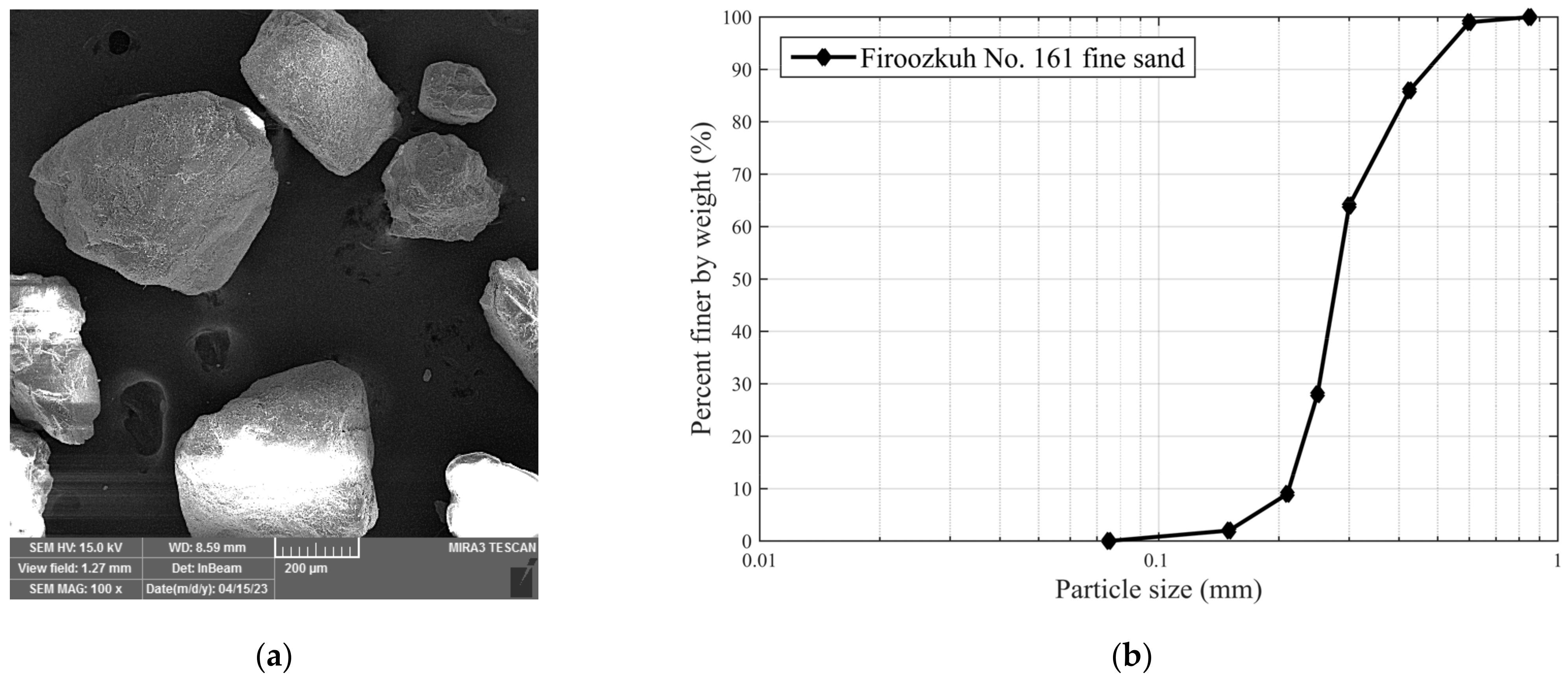
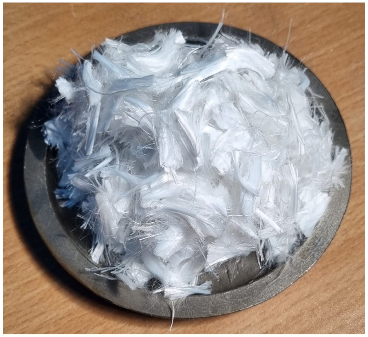
2.1. Sand and Employed Polypropylene Fibres

This experimental study utilized Firoozkuh No. 161 Sand (FRS), a standard building sand derived from crushed parent rocks sourced from the Firoozkuh area in northern Iran. The mechanical behaviour of FRS has been subjected to testing by multiple researchers in recent years [22,32]. The sand particles are angular to sub-angular in shape, as demonstrated in Figure 1a, a Scanning Electron Microscope (SEM) image. The particle size distribution was derived in compliance with the methods in ASTM [33] and is presented in Figure 1b. Physical characteristics are summarized in Table 1.
The polypropylene fibres utilized in the study are illustrated in Figure 2. Mechanical and physical properties are listed in Table 2. Flexible fibres, such as polypropylene-type fibres, can abstract and reproduce certain traits of plant roots. However, significant disparities exist between mechanical properties of fibres and natural roots, such as tensile strength and flexibility. Nevertheless, studying the behaviour of sands mixed with flexible fibres can inform the design of earth structures reinforced with natural roots.

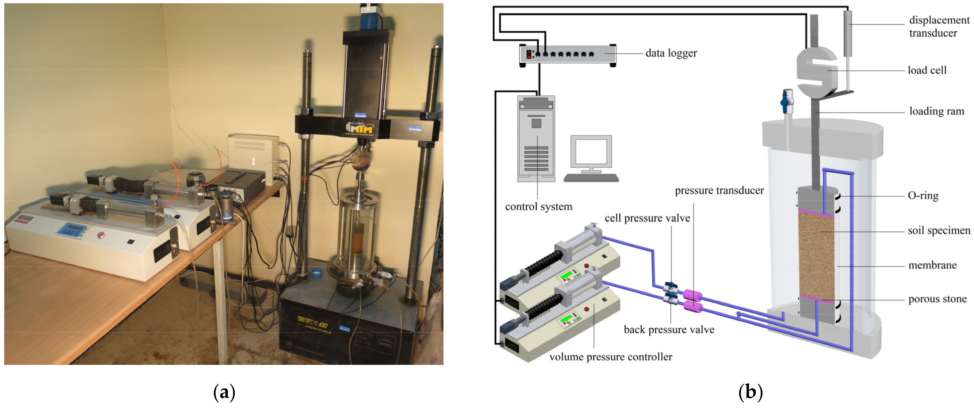
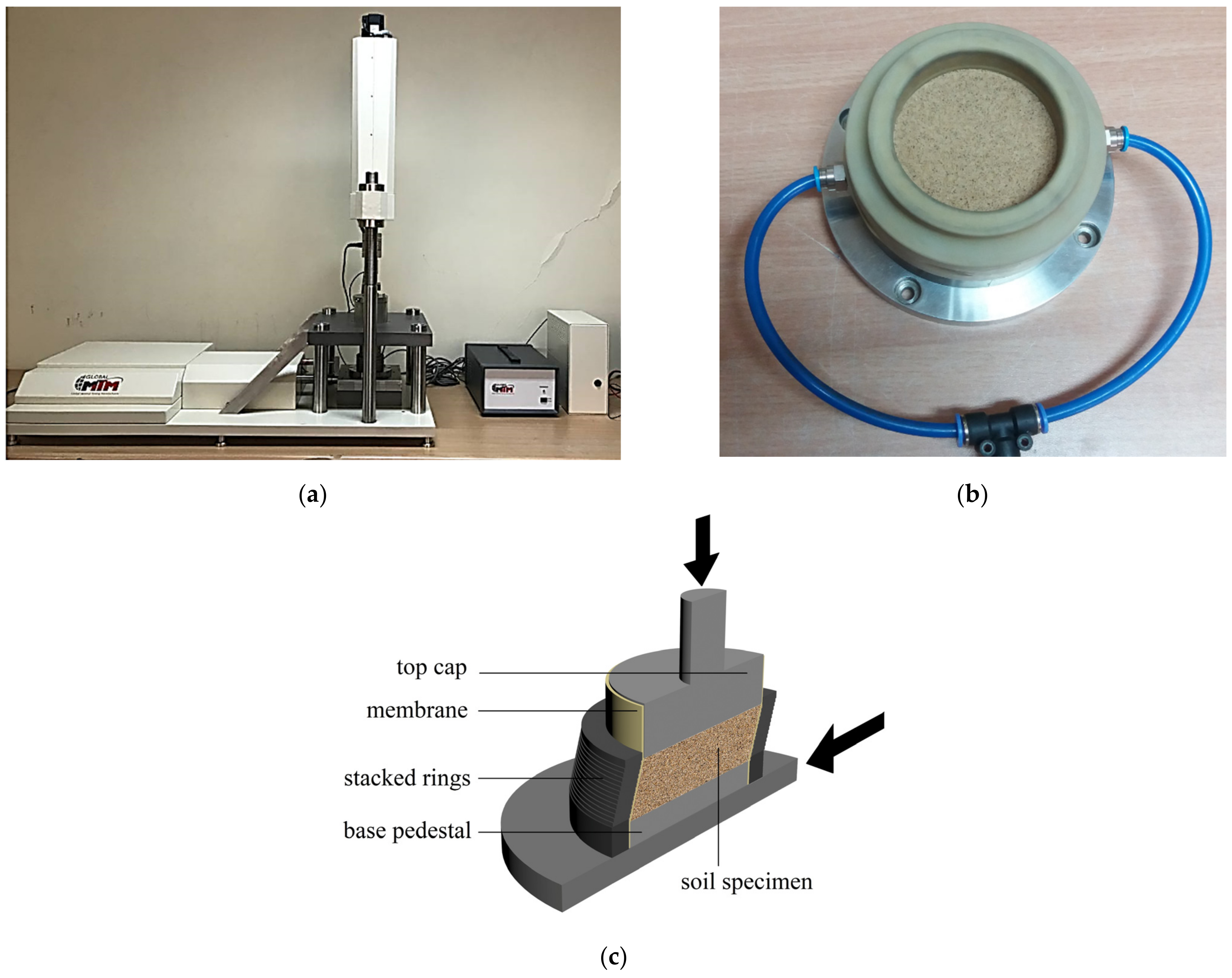
2.2. The Triaxial Shear Test Apparatus and Applied Paths

The Triaxial shear (TX) test setup employed in the current study is presented in Figure 3a. A schematic diagram of the triaxial device and test specimen is shown in Figure 3b. Specimens were remoulded to 50 mm in diameter and 100 mm in height through wet tamping at 7% water content. Tamping took place in five layers (each 20 mm thick) within the split mould while the specimen rested on the pedestal. To facilitate the removal of the split mould and minimise disruptions to the shape and fabric of the remoulded specimen, a small 14 to 15 kPa vacuum pressure was applied to the back pressure. The pressure chamber was assembled and filled with water. A modest cell pressure was then applied, and the vacuum was simultaneously released. The saturation process constituted passing CO2 through the specimen from the lower drain point, upwards, for 30 min. This was followed by passing distilled and deaired water, three times the specimen volume, through the test specimen. Pore water pressure and cell pressure were always kept balanced. A B-Skempton value of 0.95 was taken as manifestation of the completion of the saturation process. Two Digital Volume Pressure Controllers (DVPCs) were employed to regulate cell pressure, inject water into specimens during the tests, and measure the resulting volume changes. The partially drained tests encompassed both the water efflux and influx during the shear phase, enabling contractive and expansive partially drained strain paths. The findings from the partially drained tests were then compared with those of conventional consolidated drained (CD) and consolidated undrained (CU) paths. The partially drained tests (including the consolidated undrained experiments, representing a special case of strain paths) were conducted under strain-controlled conditions. The consolidated drained experiments, however, could not be considered fully strain-controlled due to the governing constant cell pressure during these tests.
Details of the conducted triaxial tests are presented in Table 3. In Table 3, ‘CU’ denotes conventional Consolidated Undrained tests, ‘CD’ represents conventional Consolidated Drained tests, and ‘PD’ indicates consolidated Partially Drained.
The CU tests were performed at a strain rate of 0.5 mm/min, while the CD tests were conducted at a strain rate of 0.05 mm/min. Partially drained tests were conducted using the pre-determined values of the v/a (volumetric strain per axial strain) ratio during tests, allowing for the control of the volumetric strains during shearing. Volumetric strains were applied bi-linearlybilinearly, as shown in Figure 4; hence, the soil’s ultimate state can be regarded as being equivalent to the steady state (because of the constant volumetric strains at the ultimate state of the shearing). In this paper, the term ‘steady state’ is used for the ultimate behaviour of testing materials, where constant stress ratios and volumetric strains are attained.

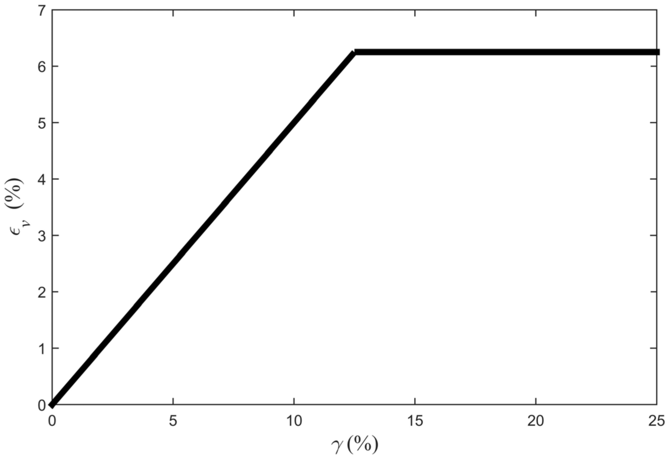
2.3. The Direct Simple Shear Test Apparatus and Applied Paths

In addition to triaxial shear tests, the behaviour of sand fibre composites under various strain paths was also examined using the Direct Simple Shear (DSS) apparatus. The DSS equipment utilized, as illustrated in Figure 5a, is a completely automated stack-ring-type simple shear device. Figure 5b depicts a prepared specimen positioned within the DSS cell. Figure 5c illustrates a schematic cross-section of the DSS device. Strain paths were applied to samples through a fixed volumetric to shear strain rate ( d ε v / d γ ). Bilinear strain paths were utilized in a manner comparable to triaxial shear tests, allowing the specimens to attain their steady state at ultimate pressures. Figure 6 presents a selection of the strain paths that were examined during this study.
The test programme for the DSS tests is presented in Table 4. In Table 4, ‘PD’ denotes partially drained, and ‘CV’ refers to consolidated constant volume. In the context of the DSS test, consolidated Constant Volume (CV) and consolidated Constant Pressure (CP) strain–stress paths are analogous to the consolidated undrained and consolidated drained paths in triaxial tests. Test specimens were subjected to bilinear strain paths, where the volumetric and shear strains were predetermined (as illustrated in Figure 6). Emphasis was put on evaluating the combined effect of varying strain paths and fibre concentrations on the strength characteristics of the base FRS sand. The partially drained scenario considered the associated volumetric and shear strains, as discussed in earlier studies conducted by Tohidvand et al. [22].

3. Results and Discussion

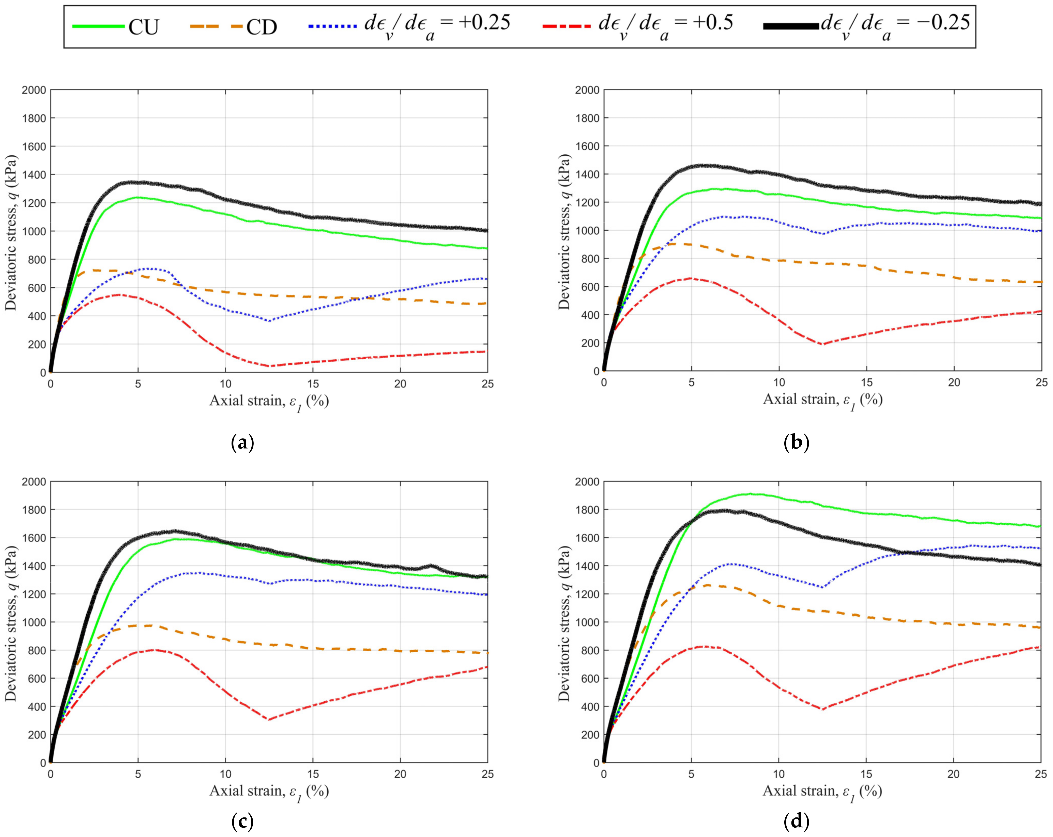
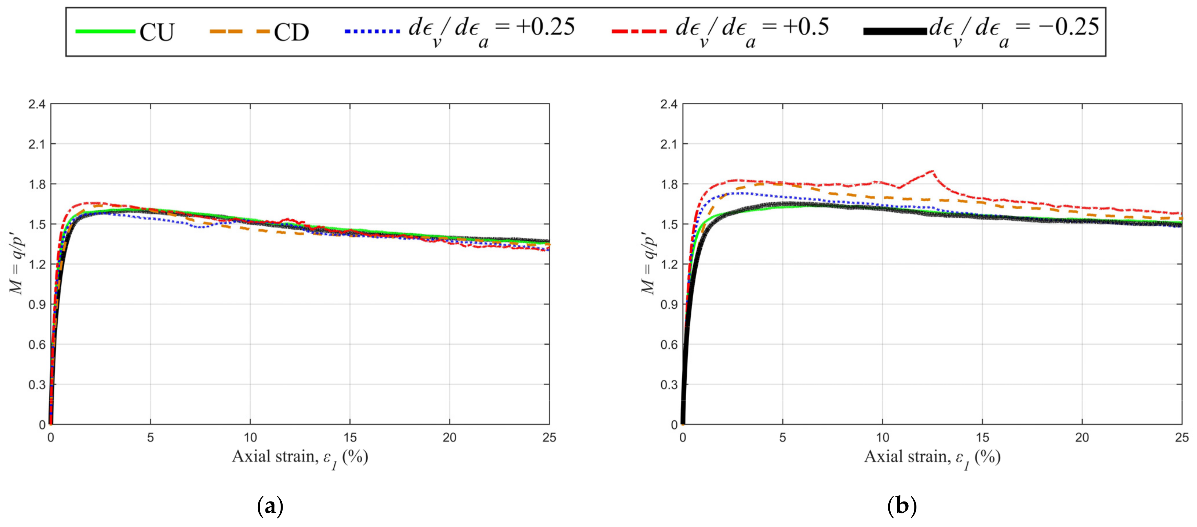
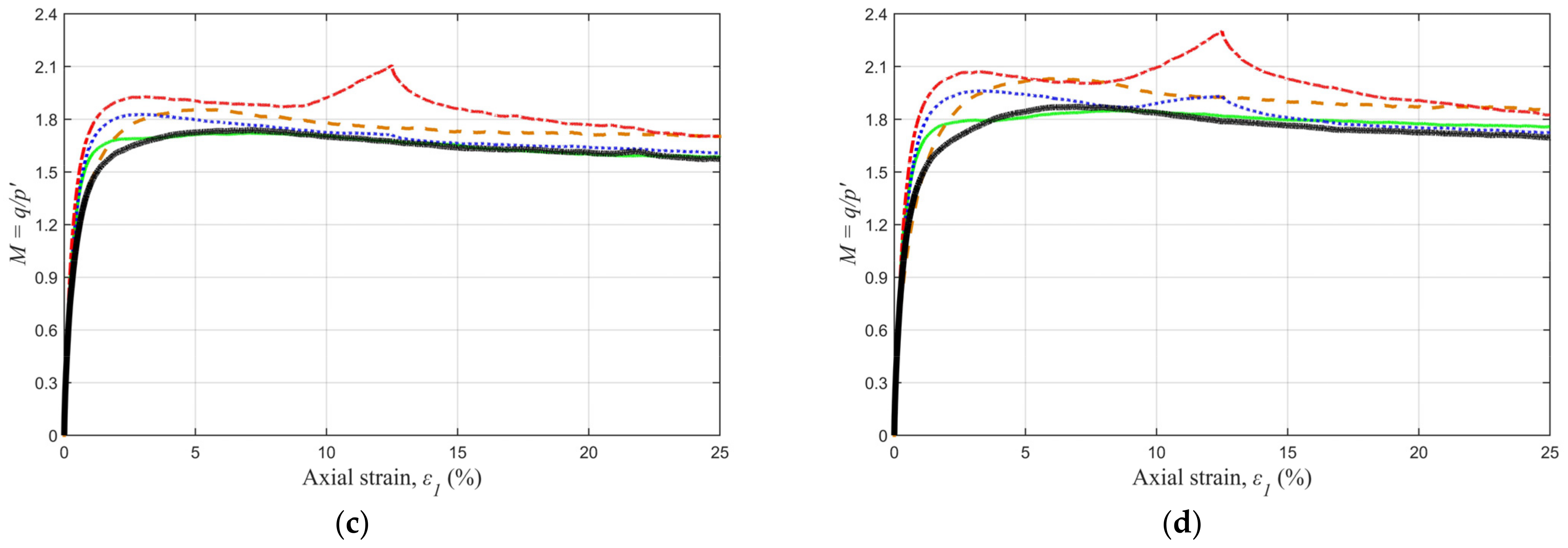
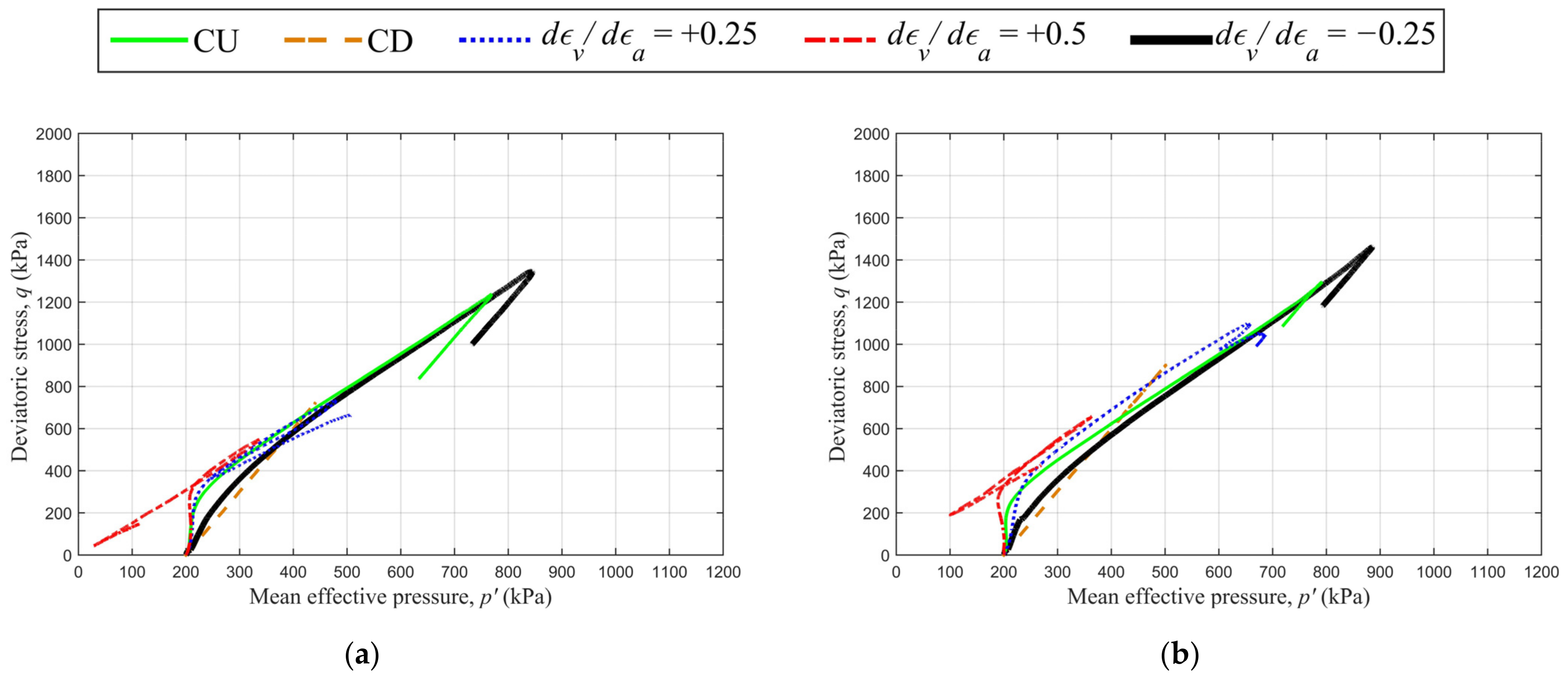
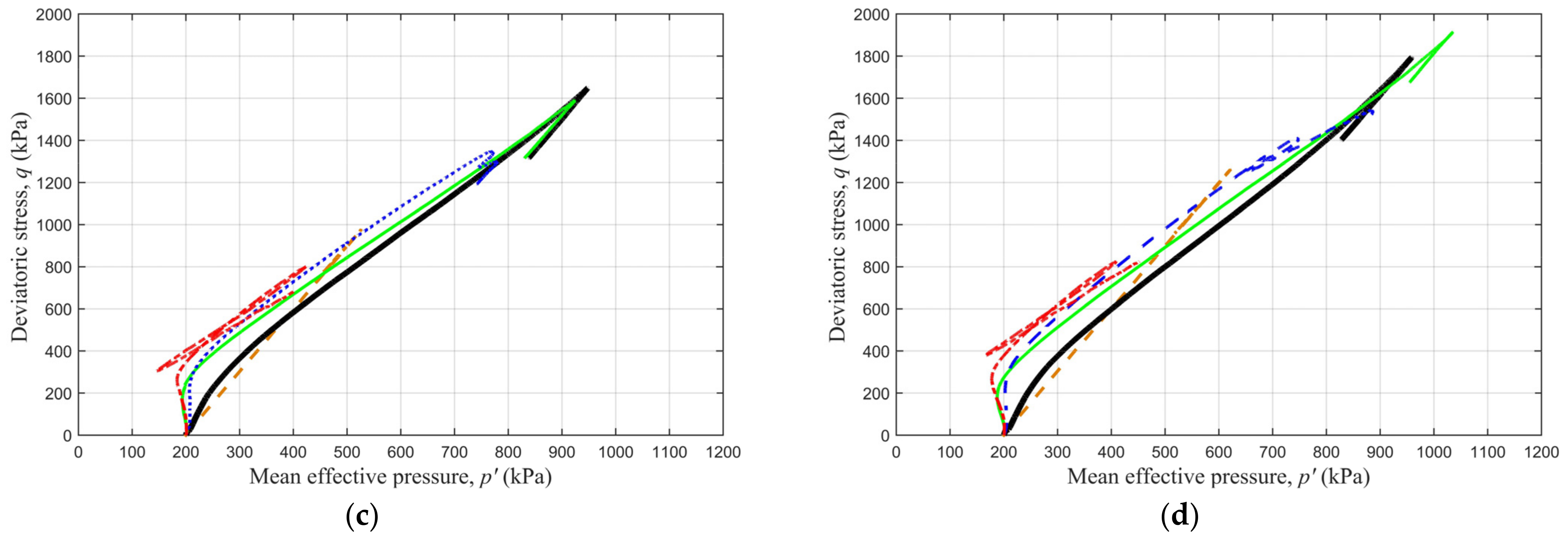
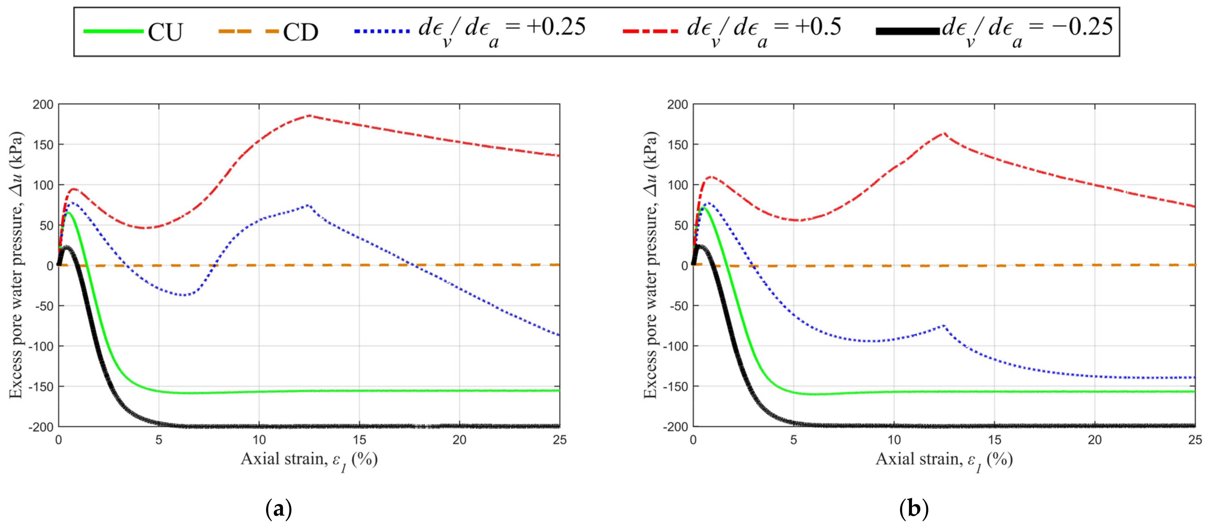
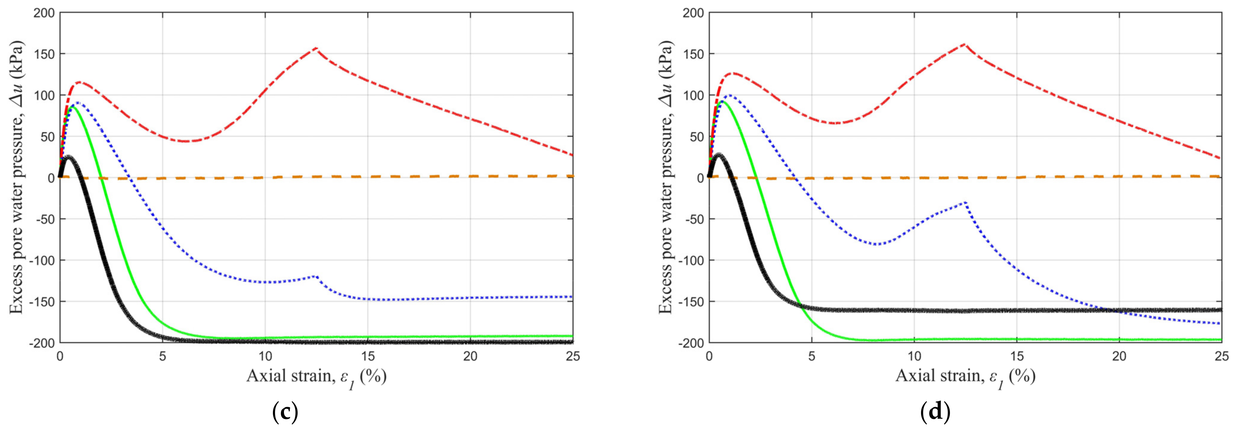
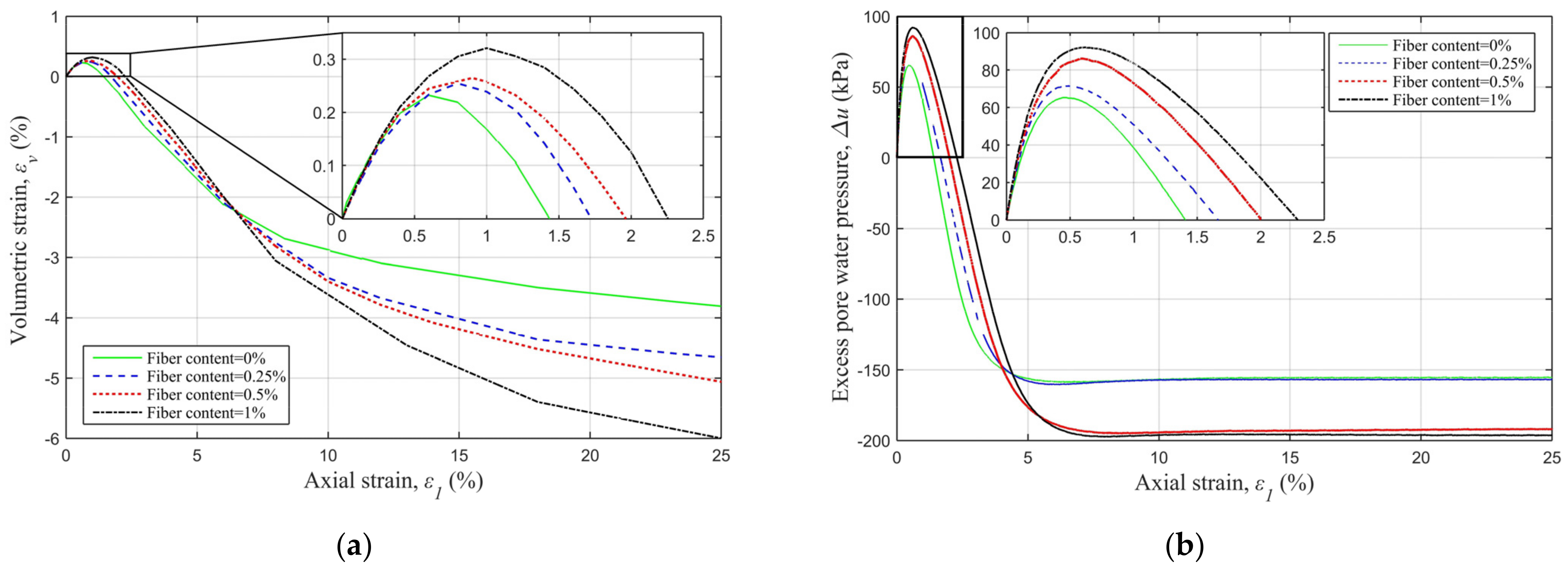
3.1. Findings from the Triaxial Shear (TX) Tests

The effect of the polypropylene fibres on deviatoric stress is evident in Figure 7. Fibres in sand yields an increase in peak deviatoric stress, regardless of drainage conditions.
A rapid inspection of the diagrams suggests that contractive partially drained paths yield deviatoric stresses remarkably higher than those attained under either undrained or drained stress–strain paths. For example, for clean sand, the path associated to fixed d ε v / d ε a = 0.25 % led to 13.6% higher peak deviatoric stress compared to the conventional consolidated undrained path. In contrast to the contractive strain path, the expansive strain paths (with positive values of v/a) yielded significantly lower deviatoric stresses compared to the consolidated undrained path (82.7% lower in the case of d ε v / d ε a = + 0.25 % ). In Figure 7a–c, at d ε v / d ε a = + 0.25 % and as the fibre content incremented from 0% to 0.5%, the peak deviatoric stress increased and exceeded the levels attained through the CD path. However, at the same d ε v / d ε a = + 0.25 % , a further increase in fibre content from 0.5% to 1% led to a reduction in the observed differences between peak values attained in CD and PD tests (Figure 7d).
In Figure 7, both CD and CU paths in clean sand exhibited a post-peak strain-softening behaviour; the post-peak response of fibre-reinforced sands, however, appeared to be strictly strain-path-dependent. For expansive paths, after reaching the target volumetric strain (at 12.5% axial strain), the deviatoric stress began to increase (except for sand with 0.25% fibre under d ε v / d ε a = + 0.25 % ). For contractive strain paths, the post-peak behaviour appeared to be somewhat similar to that of the conventional CU tests.
Clean sands, and sands with fibre content below a threshold, exhibited lower peak deviatoric stresses under CU conditions compared to contractive PD conditions. Sands with fibre content above the threshold developed higher peak deviatoric stresses under conventional CU conditions compared to the PD condition.
In Figure 8, the applied strain paths appear to have almost no significant effect on the ultimate stress ratios ( P 0 = 200 kPa), both in clean and in fibre-reinforced sands. In clean sand, the stress ratios are consistent across all strain paths throughout the test. However, as the fibre content increases, the disparity in stress ratios in the initial strains becomes more pronounced. Nevertheless, with an increase in axial strain, the difference in stress ratios in the strain paths gradually diminishes. Although the impact of strain paths on ultimate stress ratios appears to be minimal, the influence of fibre contents is significant. As evident in Figure 8, the ultimate stress ratio is directly associated with fibre content. For example, clean sands exhibit an average stress ratio of 1.33. In contrast, when sands are blended with 0.25%, 0.5%, and 1% fibres, the stress ratios rise to 1.53, 1.64, and 1.75, respectively. As the fibre content increases, the stress ratio reaches its maximum at a higher axial strain. In expansive paths, the stress ratio reaches its peak at a smaller strain when compared to the conventional CD path. Conversely, in contractive strain paths ( d ε v / d ε a = 0.25 % ), the stress ratio reaches its maximum value at a higher axial strain.
Strain paths applied to the dense FRS specimens are illustrated in Figure 9. The entire specimen population (under CU and PD paths) exhibits a low level of contractive behaviour followed by dilation until reaching the targeted volumetric strain. After reaching the constant volumetric strain state, specimens approached their ultimate stress states. For tests in which water influx was allowed (i.e., expansive paths with d ε v / d ε a = + 0.5 % ), a reduction in mean effective stress values was evident (Figure 9). For example, the clean sand specimen with d ε v / d ε a = + 0.5 % is almost close to the liquid state. By increasing the fibre content from 0% to 1%, the reduction seen in the mean effective stresses ( d ε v / d ε a = + 0.5 % ) began to fade.
Figure 10 illustrates the evaluation of induced pore water pressures. In Figure 10, the fibre content appears to have a significant effect on excess pore water pressure distribution. Although the pore water pressure distribution is mainly influenced by fibre content and the induced strain paths, the maximum and minimum pore water pressures appear to be almost constant (+185 kPa and −200 kPa). Initially, all specimens exhibit a contractive behaviour (equivalent to the negative pore water pressures), followed by a phase transition that shifts the behaviour towards dilative (equivalent to the positive pore water pressures). In the case of expansive paths (with d ε v / d ε a = + 0.5 % and d ε v / d ε a = + 0.25 % ), the behaviour reverts to a contractive state. This reversion can be attributed to the higher rate of water influx compared to the dilation rate. The findings suggest that fibre content is directly associated with the extent of dilative and contractive behaviour in the initial stage. In addition, an increased fibre content relaxes the effects of the strain paths on the excess pore water pressure. As shown in Figure 10d, for sand mixed with 1% of fibre, the EPWP under d ε v / d ε a = 0.25 % approached the CD test results, and the tests with strain paths d ε v / d ε a = + 0.5 % and + 0.25 % approached the EPWP results of the CU tests.
Figure 11a illustrates the impact of increasing fibre content on the variations in volumetric strain during drained tests. Figure 11b shows the variations in excess pore water pressure during undrained tests. It is evident that elevating the fibre content results in an enhancement of both initial contractive behaviour and subsequent dilative behaviour. Notably, in Figure 11a, the test with 1% fibre content exhibits maximum expansion at low strains and maximum contraction at larger strains. Similarly, in Figure 11b, specimens with 1% fibre content mark the largest positive excess pore water pressure (about Δ u = + 92 kPa) at low strains, as well as the largest negative pore water pressure (about Δ u = 197 kPa) at larger strains. Furthermore, as the fibre content increases, the phase transition, observed in both drained and undrained tests, occurs at a greater axial strain, as elucidated in the enlarged figures.

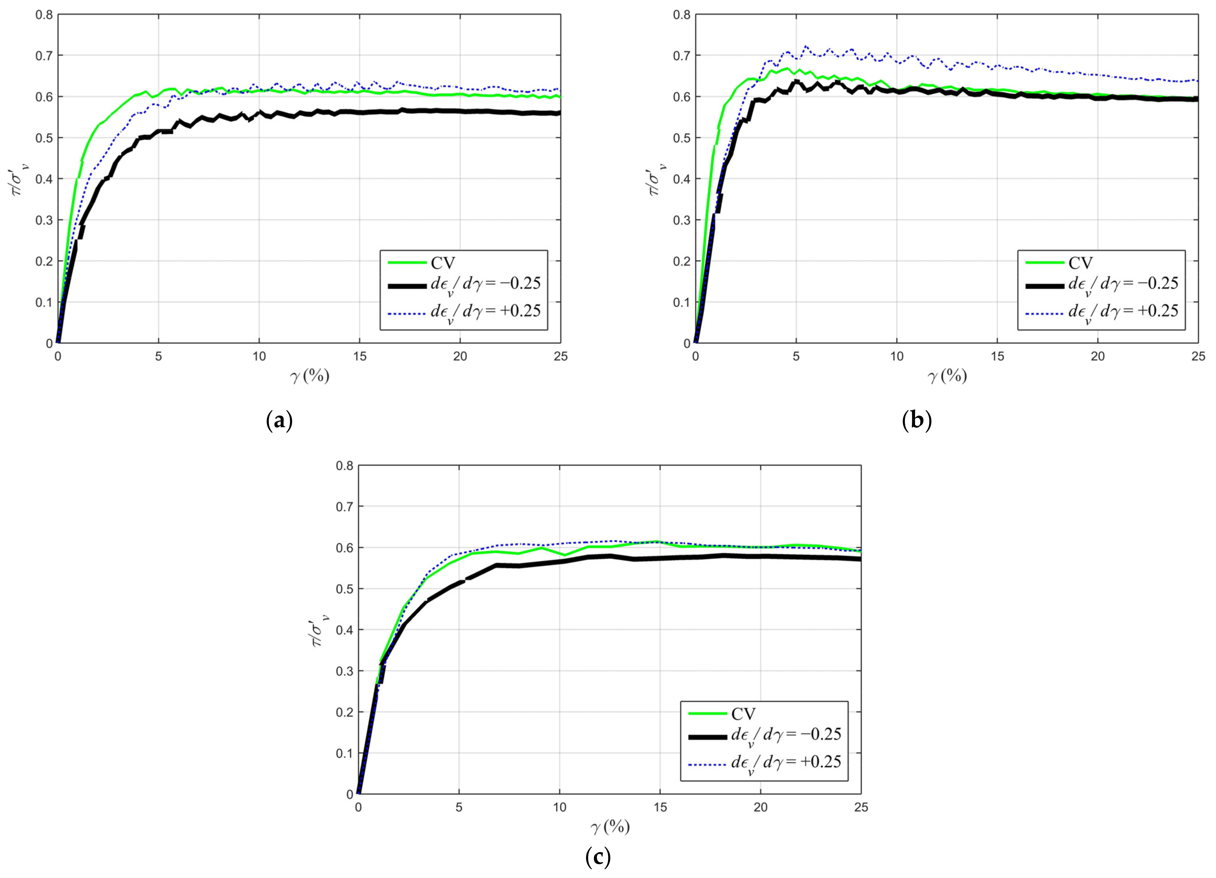
3.2. Findings from the Direct Simple Shear Tests (DSS)

To compare the effects of the shear mode on the ultimate stress ratios of the fibre-reinforced sands, nine DSS tests were carried out. To this end, the results of the partially drained tests on the polypropylene-reinforced sands (Firoozkuh sand) were employed. These DSS tests were applied on sand, with the same relative density as used in the current research (70%). The achieved results for the stress ratios are shown in Figure 12. As this figure demonstrates, under the direct simple shear mode of loading, the experienced ultimate stress ratio changes depending on the fibre content. By increasing the fibre content from zero (clean sand) to 0.5%, the effects of the strain paths on the experienced ultimate stress ratios were decreased. For FC = 0.5%, all three applied strain paths show almost the same ultimate stress ratios.
By comparing the ultimate stress ratios of specimens subjected to direct simple and triaxial shear tests, the effects of the shear mode were evaluated. Similar strain paths were selected for comparison. In Figure 13, the ultimate stress ratio varies with the strain path. The variation is dependent on both applied shearing mode and fibre content.
Under the triaxial shear mode, an increase in fibre content led to a steady increase in ultimate stress ratios, that is, +14% (from levels seen in clean sand) for specimens containing 0.25%, and +23% (from levels seen in clean sand) for specimens with 0.5% fibre content. Notably, for the higher 0.5% fibre content, greater ultimate stress ratios were achieved under both expansive and contractive strain paths as compared to undrained conditions.
Under the simple shear mode, the influence of strain path on the ultimate stress ratios is more pronounced than that under the triaxial shear mode. This can be attributed to the stress rotation capability in the DSS tests. While the direction of principle stresses is constant under triaxial shear conditions, these directions continuously vary in the direct simple shear tests. Therefore, the evolution of shear bands in soils subjected to simple shear can be more significantly influenced by the applied strain path, resulting in induced anisotropies. As the direction of principle stresses changes, the effects of the randomly distributed fibres on the developed shear bands are magnified. In other words, under a simple shear mode strain path, induced anisotropy can have a greater impact on both the soil skeleton and fibre inclusions compared to the triaxial shear mode. Such anisotropy-induced effects on the particle-to-particle and particle-to-fibre-to-particle force distribution patterns result in a notable difference in the ultimate stress ratio changes in DSS and TX shear modes.

4. Conclusions

This research presents findings from strain-controlled direct simple and triaxial shear tests on sands reinforced with flexible fibres. The key findings are as follows:
  • The experienced strain path significantly influences the ultimate and peak stress states of both clean and fibre-reinforced sands. Contractive strain paths result in higher peak deviatoric stress (v/a = −0.25% strain path led to 13.6% larger peak deviatoric stress in clean sand), while expansive strain paths yield lower peak deviatoric stress (v/a = +0.25% led to 82.72% lower peak deviatoric stress) compared to conventional CD tests.
  • In clean sand, experienced strain paths have no impact on the ultimate stress ratio. However, an increase in fibre content in samples undergoing expansive strain paths leads to an elevated ultimate stress ratio. Clean sand exhibits an average ultimate stress ratio of 1.33, but as the fibre content increases to 0.25%, 0.5%, and 1%, the average ultimate stress ratio also rises to 1.53, 1.64, and 1.75, respectively.
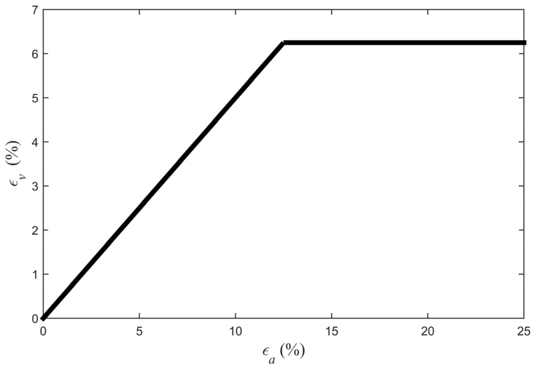
  • With an elevated fibre content, samples display a more pronounced volume reduction at initial axial strains and a more significant increase in volume at larger strains. Moreover, the increased fibre content results in a phase transition occurring at a greater axial strain.
  • In dense sands, the ultimate stress ratios under the TX shear mode exhibit limited sensitivity to the applied strain path. However, under the DSS path, greater sensitivity becomes apparent. Under the TX shear mode, the stress paths, pore water pressure generation pattern, peak shear strength, and hardening or softening behaviour of dense FRS samples are sensitive to the experienced strain paths.

Author Contributions

Conceptualization, M.H.-B.; Methodology, E.M.T. and A.A.D.; Formal analysis, E.M.T.; Investigation, E.M.T., A.A.D. and A.E.I.; Resources, A.E.I.; Writing—original draft, E.M.T.; Writing—review & editing, A.A.-L.; Supervision, M.H.-B.; Project administration, A.E.I. and A.A.-L. All authors have read and agreed to the published version of the manuscript.

Funding

This research received no external funding.

Institutional Review Board Statement

Not applicable.

Informed Consent Statement

Not applicable.

Data Availability Statement

No new data were created or analyzed in this study. Data are contained within the article.

Conflicts of Interest

The authors declare no conflict of interest.

References

  1. Macedo, J.; Vergaray, L. Properties of mine tailings for static liquefaction assessment. Can. Geotech. J. 2022, 59, 667–687. [Google Scholar] [CrossRef]
  2. Wang, R.; Fu, P.; Zhang, J.-M.; Dafalias, Y.F. Fabric characteristics and processes influencing the liquefaction and re-liquefaction of sand. Soil Dyn. Earthq. Eng. 2019, 125, 105720. [Google Scholar] [CrossRef]
  3. Adhikari, S.; Bhattacharya, S. Vibrations of wind-turbines considering soil-structure interaction. Wind. Struct. 2011, 14, 85–112. [Google Scholar] [CrossRef]
  4. Amini, P.F.; Wang, G. Integrated effects of inherent and induced anisotropy on reliquefaction resistance of Toyoura sand with different strain histories. Géotechnique 2023, 1–15. [Google Scholar] [CrossRef]
  5. Oda, M.; Koishikawa, I.; Higuchi, T. Experimental Study of Anisotropic Shear Strength of Sand by Plane Strain Test. Soils Found. 1978, 18, 25–38. [Google Scholar] [CrossRef]
  6. Arthur, J.R.F.; Chua, K.S.; Dunstan, T. Principal Stress Rotation: A Missing Parameter. J. Geotech. Eng. Div. 1980, 106, 419–433. [Google Scholar] [CrossRef]
  7. Triantafyllos, P.K.; Georgiannou, V.N.; Dafalias, Y.F.; Georgopoulos, I.-O. Novel findings on the dilatancy and non-coaxiality of sand under generalised loading. Acta Geotech. 2021, 16, 1699–1734. [Google Scholar] [CrossRef]
  8. Cho, G.-C.; Dodds, J.; Santamarina, J.C. Particle Shape Effects on Packing Density, Stiffness, and Strength: Natural and Crushed Sands. J. Geotech. Geoenviron. Eng. 2006, 132, 591–602. [Google Scholar] [CrossRef]
  9. Yamamuro, J.A.; Covert, K.M. Monotonic and Cyclic Liquefaction of Very Loose Sands with High Silt Content. J. Geotech. Geoenviron. Eng. 2001, 127, 314–324. [Google Scholar] [CrossRef]
  10. Alarcon-Guzman, A.; Leonards, G.A.; Chameau, J.L. Undrained Monotonic and Cyclic Strength of Sands. J. Geotech. Eng. 1988, 114, 1089–1109. [Google Scholar] [CrossRef]
  11. Sladen, J.A.; D’Hollander, R.D.; Krahn, J. The liquefaction of sands, a collapse surface approach. Can. Geotech. J. 1985, 22, 564–578. [Google Scholar] [CrossRef]
  12. Lade, P.V. Static Instability and Liquefaction of Loose Fine Sandy Slopes. J. Geotech. Eng. 1992, 118, 51–71. [Google Scholar] [CrossRef]
  13. Goren, L.; Aharonov, E.; Sparks, D.; Toussaint, R. Pore pressure evolution in deforming granular material: A general formulation and the infinitely stiff approximation. J. Geophys. Res. Solid Earth 2010, 115. [Google Scholar] [CrossRef]
  14. Seed, H.B. Design Problems in Soil Liquefaction. J. Geotech. Eng. 1987, 113, 827–845. [Google Scholar] [CrossRef]
  15. Boulanger, R.W.; Truman, S.P. Void redistribution in sand under post-earthquake loading. Can. Geotech. J. 1996, 33, 829–834. [Google Scholar] [CrossRef]
  16. Umehara, Y.; Zen, K.; Hamada, K. Evaluation of Soil Liquefaction Potentials in Partially Drained Conditions. Soils Found. 1985, 25, 57–72. [Google Scholar] [CrossRef]
  17. Vaid, Y.P.; Eliadorani, A. Instability and liquefaction of granular soils under undrained and partially drained states. Can. Geotech. J. 1998, 35, 1053–1062. [Google Scholar] [CrossRef]
  18. Eckersley, J. Flowslides in stockpiled coal. Eng. Geol. 1985, 22, 13–22. [Google Scholar] [CrossRef]
  19. Wanatowski, D.; Chu, J.; Lo, R.S.-C. Strain-softening behaviour of sand in strain path testing under plane-strain conditions. Acta Geotech. 2008, 3, 99–114. [Google Scholar] [CrossRef]
  20. Chu, J.; Lo, S.C.R.; Lee, I.K. Instability of Granular Soils under Strain Path Testing. J. Geotech. Eng. 1993, 119, 874–892. [Google Scholar] [CrossRef]
  21. Adamidis, O.; Madabhushi, S.P.G. Experimental investigation of drainage during earthquake-induced liquefaction. Géotechnique 2018, 68, 655–665. [Google Scholar] [CrossRef]
  22. Tohidvand, H.R.; Hajialilue-Bonab, M.; Katebi, H.; Nikvand, V.; Ebrahimi-Asl, M. Monotonic and post cyclic behavior of sands under different strain paths in direct simple shear tests. Eng. Geol. 2022, 302, 106639. [Google Scholar] [CrossRef]
  23. Logeswaran, P.; Sivathayalan, S. A New Hollow Cylinder Torsional Shear Device for Stress/Strain Path Controlled Loading. Geotech. Test. J. 2014, 37. [Google Scholar] [CrossRef]
  24. Gray, D.H.; Ohashi, H. Mechanics of Fiber Reinforcement in Sand. J. Geotech. Eng. 1983, 109, 335–353. [Google Scholar] [CrossRef]
  25. Diambra, A.; Ibraim, E. Fibre-reinforced sand: Interaction at the fibre and grain scale. Géotechnique 2015, 65, 296–308. [Google Scholar] [CrossRef]
  26. Consoli, N.C.; Casagrande, M.D.T.; Prietto, P.D.M.; Thomé, A. Plate Load Test on Fiber-Reinforced Soil. J. Geotech. Geoenviron. Eng. 2003, 129, 951–955. [Google Scholar] [CrossRef]
  27. Pincus, H.; Maher, M.; Ho, Y. Behavior of Fiber-Reinforced Cemented Sand Under Static and Cyclic Loads. Geotech. Test. J. 1993, 16, 330. [Google Scholar] [CrossRef]
  28. Zhang, X.; Russell, A.R.; Dong, X. Liquefaction responses of fibre reinforced sand in shaking table tests with a laminated shear stack. Soil Dyn. Earthq. Eng. 2022, 162, 107466. [Google Scholar] [CrossRef]
  29. Noorany, I.; Uzdavines, M. Dynamic behavior of saturated sand reinforced with geosynthetic fabrics. Geosynthetics 1989, 2, 385–396. [Google Scholar]
  30. Consoli, N.C.; Casagrande, M.D.T.; Coop, M.R. Performance of a fibre-reinforced sand at large shear strains. Géotechnique 2007, 57, 751–756. [Google Scholar] [CrossRef]
  31. Diambra, A.; Ibraim, E.; Russell, A.R.; Wood, D.M. Fibre reinforced sands: From experiments to modelling and beyond. Int. J. Numer. Anal. Methods Géoméch. 2013, 37, 2427–2455. [Google Scholar] [CrossRef]
  32. Tohidvand, H.R.; Tabrizi, E.M.; Irani, A.E.; Hajialilue-Bonab, M.; Farrin, M. Effects of the Fiber Reinforcement on the Monotonic Behavior of Sands Considering Coupled Volumetric–Shear Strain Paths. Int. J. Geosynth. Ground Eng. 2023, 9, 1–15. [Google Scholar] [CrossRef]
  33. ASTM D 6913-04(2009)e1; Standard Test Methods for Particle-Size Distribution (Gradation) of Soils Using Sieve Analysis. ASTM Standards: West Conshohocken, PA, USA, 2014. [CrossRef]
  34. ASTM D5550-14; Standard Test Method for Specific Gravity of Soil Solids by Gas Pycnometer. ASTM Standards: West Conshohocken, PA, USA, 2023. [CrossRef]
  35. ASTM D4253-16e1; Standard Test Methods for Maximum Index Density and Unit Weight of Soils Using a Vibratory Table. ASTM Standards: West Conshohocken, PA, USA, 2019. [CrossRef]
  36. ASTM D4254-16; Standard Test Methods for Minimum Index Density and Unit Weight of Soils and Calculation of Relative Density. ASTM Standards: West Conshohocken, PA, USA, 2016. [CrossRef]
Figure 1. Firoozkuh No. 161 sand: (a) particle shape in SEM image; (b) particle size distribution.
Sustainability 15 16286 g001
Figure 2. Polypropylene fibres.
Sustainability 15 16286 g002
Figure 3. The apparatus used for triaxial tests: (a) overall setup; (b) schematic image of the used device.
Sustainability 15 16286 g003
Figure 4. A sample bilinear strain path adopted for partially drained triaxial tests.
Sustainability 15 16286 g004
Figure 5. Direct simple shear test: (a) overall setup; (b) prepared specimen; (c) schematic cross-section of DSS encompassing a specimen.
Sustainability 15 16286 g005
Figure 6. A sample bilinear strain path adopted for DSS tests.
Sustainability 15 16286 g006
Figure 7. The influence of varying fibre percentages on deviatoric stress over different strain paths: (a) clean sand; (b) FRS with 0.25% fibre; (c) FRS with 0.5% fibre; (d) FRS with 1% fibre. Note: ε a and ε l concurrently represent axial strain.
Sustainability 15 16286 g007
Figure 8. The influence of varying fibre percentages on the stress ratios over different strain paths: (a) clean sand; (b) FRS with 0.25% fibre; (c) FRS with 0.5% fibre; (d) FRS with 1% fibre.
Sustainability 15 16286 g008aSustainability 15 16286 g008b
Figure 9. The influence of varying fibre percentages on the experienced stress paths over different strain paths: (a) clean sand; (b) FRS with 0.25% fibre; (c) FRS with 0.5% fibre; (d) FRS with 1% fibre.
Sustainability 15 16286 g009aSustainability 15 16286 g009b
Figure 10. The influence of varying fibre percentages on the excess pore water pressure distribution over different strain paths: (a) clean sand; (b) FRS with 0.25% fibre; (c) FRS with 0.5% fibre; (d) FRS with 1% fibre.
Sustainability 15 16286 g010aSustainability 15 16286 g010b
Figure 11. The influence of varying fibre percentages on (a) the volumetric strain and (b) the generation of excess pore water pressure.
Sustainability 15 16286 g011
Figure 12. Effects of the fibre content on the stress ratios under different strain paths using DSS tests: (a) clean sand; (b) FRS with 0.25% fibre; (c) FRS with 0.5% fibre.
Sustainability 15 16286 g012
Figure 13. Comparison between ultimate stress ratios achieved under triaxial shear and direct simple shear modes, considering effects of fibre content and strain paths.
Sustainability 15 16286 g013
Table 1. Physical properties of Firoozkuh No. 161 sand.
Specific   Gravity ,   G s [34] Median   Diameter ,   D 50 (mm) [33] Maximum   Void   Ratio ,   e m a x [35] Minimum   Void   Ratio ,   e m i n [36]
2.650.270.950.55
Table 2. Mechanical and physical properties of polypropylene fibres (provided by the manufacturer).
Particle   Density ,   ρ s   ( g · c m 3 )Tension Strength,
( N · m m 2 )
Mean
Thickness, ( m m )
Elastic
Modulus ( M P a )
Mean
Length
( m m )
913500.02562005
Table 3. Programme of triaxial shear tests (TX).
Consolidation
Stress (kPa)
Initial Relative Density (%)Type of the Test d ε v / d ε a (%)Fibre Content, FC (%)
20072.59CU00
20070.79CD-0
20072.73PD−0.250
20071.86PD0.250
20072.2PD0.50
20072.22CU00.25
20072.78CD-0.25
20070.69PD−0.250.25
20071.69PD0.250.25
20072.63PD0.50.25
20072.84CU00.5
20073.59CD-0.5
20072.8PD−0.250.5
20072.45PD0.250.5
20071.07PD0.50.5
20070.36CU01
20071.31CD-1
20072.43PD−0.251
20071.46PD0.251
20072.74PD0.51
Table 4. Programme of direct simple shear tests (DSS).
Consolidation
Stress (kPa)
Initial Relative Density (%)Type of the Test d ε v / d γ  (%)Fibre Content, FC (%)
20071.2CV00
20070.6PD−0.250
20071.5PD0.250
20071.3CV00.25
20072.1PD−0.250.25
20072.3PD0.250.25
20072.5CV00.5
20072.8PD−0.250.5
20072.1PD0.250.5
Disclaimer/Publisher’s Note: The statements, opinions and data contained in all publications are solely those of the individual author(s) and contributor(s) and not of MDPI and/or the editor(s). MDPI and/or the editor(s) disclaim responsibility for any injury to people or property resulting from any ideas, methods, instructions or products referred to in the content.

