Abstract
The need to increase the level of beneficial recycling of municipal solid waste (MSW) and the focus on low-carbon energy are increasing interest in the production of hydrogen from MSW. The presence of free space and excess capacity makes thermal power plants (TPPs) the most rational objects for the integration of units that produce hydrogen from MSW. The use of heat pumps (HP) will make it possible to use waste heat, increase heat output, and optimize the TPPs’ operating modes. The purpose of the study is to analyze the effectiveness of using HPs in the scheme for producing hydrogen from MSW at TPPs. The integration of a hydrogen-generating unit into the thermal circuit of a TPP will provide the necessary amount of vapor for the production of hydrogen but will lead to a decrease in the thermal efficiency of the plant. The use of HP will partially compensate for this decrease. For plants with a turbine of type T-100/120-130, when using HPs to heat network water, the reduction in electricity generation will be 1.9–32.0%, and the increase in heat supply will be 1.7–14.2%. The reduction in specific fuel consumption for an electricity supply will be 0–1.2%, an increase in marginal profit of 0.1–6.4%, with the MSW disposal of 10–90 t/h, and the hydrogen generation of 0.8–18.9 t/h.
1. Introduction
A significant factor negatively affecting the environmental safety of the Russian Federation is a steady increase in the volume waste generation, with a low level of its disposal [1]. So, between 2019 and 2022 the total increase in the volume of waste generation was 16.3%, whereas the average level of utilization did not exceed 46–50% (at the same time, only 18–30% was sent for reuse (recycling), and the volume of waste disposal was continuously increasing (Table 1)) [2,3]. Despite the emerging in the period 2019–2022 trend towards a decrease in the volume of formation of municipal solid waste (MSW) in the territory of the Russian Federation, its share sent for disposal did not exceed 4–7%, whereas the share of burial was 72–92% (Figure 1).

Table 1.
Dynamics of generation, disposal of production and consumption waste in the Russian Federation, million tons.
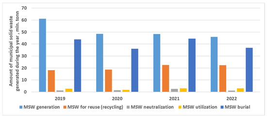
Figure 1.
Comparative information on municipal solid waste in the Russian Federation for 2019–2022. Note: Prepared according to the Federal Service for Supervision of Natural Resources.
The leaders in the field of MSW recycling are Japan, where 75% of MSW is recycled, the USA—46%; Switzerland—53% [1]; Denmark—46.3%; The Netherlands—51.7%; Germany—66.1%; Sweden—48%; France—39.5% [4].
A fundamental change at the state level in the approach to waste management based on a large-scale transition from a significant share of waste storage to an efficient waste disposal with a high component of recycling would not only increase the level of efficiency in the use of natural resources but would also reduce the environmental load due to economic and other activities. This is especially relevant in the context of global climate change, as well as growing economic activity both in Russia and in the world.
Nowadays, the main options for MSW disposal are recycling, storage at landfills, thermal disposal of waste (including direct combustion, pyrolysis, gasification, etc.), and composting. Utilization of MSW with the by-product production of electrical energy and heat would, in addition to partially solving the problem of waste disposal, also reduce the share of organic fuel in the Russian fuel and energy balance (FEB). Unfortunately, the volumes of MSW used in this way in the Russian Federation amounted to 24.1 and 19.9 thousand tons/year, respectively, in 2020 and 2021, with a total volume of waste production at the level of 48.5 and 48.4 million tons/year [2].
Direct combustion is the most common method of using MSW for energy supply needs. However, its application depends on the waste calorific value, which is affected by the waste morphological composition, which may have seasonal fluctuations and differ by region. In addition, the implementation of the technological process of MSW combustion involves the use of specialized devices, as well as equipment to suppress emissions of harmful substances contained in flue gases and utilize the non-combustible part of the waste [5].
Technologies that involve the conversion of the organic part of MSW into a mixture of combustible gases, with their subsequent use in power plants of various types, are quite promising [5]. As the synthesis gas obtained from waste as a result of thermochemical conversion (gasification and pyrolysis) is a mixture of carbon monoxide and hydrogen, additional opportunities open up for the disposal of MSW with the production of an environmentally friendly type of fuel. This may be of particular importance in the context of the focus on low-carbon economic development, fixed at the level of official documents of state strategic planning, including through the formation of Russian hydrogen energy sector [6].
It is predicted that hydrogen, used in the Russian Federation mainly in the chemical and petrochemical industries, can over time become a new energy carrier, partially replacing hydrocarbons in fuel and energy balance [6]. This will be facilitated by the implementation at the state level of a whole range of activities, including support for the development and implementation of new and expansion of the practice of using existing low-carbon technologies for hydrogen production, as well as the creation of infrastructure for its transportation and consumption [6].
Nowadays, serious scientific work is being carried out all over the world aimed at developing and justifying technical solutions that help reduce the negative impact on the environment through the production of carbon-free fuel and effective waste disposal. Research is being conducted on various technologies for hydrogen production (for example, electrolysis [7], steam methane reforming [8], method of methane pyrolysis [9], coal gasification [10], gasification of woody biomass [11], and their comparative analysis (for example, [12,13,14])) and also evaluates the economic efficiency of individual methods in different energy systems (for example, Croatia [9], Sweden [15], Germany [16], Poland [10,17], Great Britain [14], and Slovenia [18]). The technical and economic aspects of hydrogen production at existing power plants are considered (for example, thermal power plants [9], hydroelectric power plants [18,19], and nuclear power plants [20]).
There are scientific publications devoted to the analysis of the prospects for the production of biofuel and bioenergy from waste (for example, [21,22]). Studies are conducted to analyze the impact of changes in the morphological composition of waste on the efficiency of the MSW gasification process [23].
Serious scientific studies in this area are also carried out in Russia. The analysis of the possibility of implementing individual stages of the technological chains of hydrogen energy is carried out [24,25,26]. A few scientific articles develop the technical and economic basis to produce hydrogen by various methods (for example, electrolysis [27], methane pyrolysis [28], and steam reforming of methane [29]). Technical solutions are proposed for the implementation of units to produce hydrogen at existing energy facilities in the conditions of various energy systems (for example, thermal power plants with CCGT units in Tatarstan [27], hydroelectric power plant in the Magadan region [30], and nuclear power plants [20]).
The world and Russian experience of recycling waste for the needs of energy supply is studied [31], methodological issues of energy use of MSW and their gasification products are developed [4,32], and operating parameters of MSW gasification units are analyzed [33].
Despite the theoretical foundations of hydrogen production by various methods at thermal power plants that have been worked out in sufficient detail, several issues related to its generation from MSW are still not fully investigated. In particular, the issue of utilization of waste heat removed from synthesis gas in the production of hydrogen by the method of pressure swing adsorption (PSA) remains unresolved.
The use of waste low-potential heat in heat pumps (HPs) is one of the promising areas for energy saving at thermal power plants [34]. Abroad, HPs have long established themselves as an efficient and environmentally friendly technology that can significantly increase the degree of involvement of low-temperature energy resources in the country’s FEB [35,36,37]. Therefore, the creation on the basis of Russian thermal power plants of units for the production of hydrogen from MSW with the utilization of waste heat with the help of heat pumps will contribute to the solution of a number of global environmental problems, including:
- partial solution of the problem of MSW disposal;
- development of hydrogen production and consumption infrastructure;
- diversification of fuel and energy balance;
- increase in the efficiency of existing heat and power equipment;
- reduction in greenhouse gas emissions;
- increase in the level of waste heat use;
- reduction in water consumption of TPPs’ cooling systems.
The purpose of this study is to analyze the efficiency of using heat pumps for the utilization of low-potential heat in a hydrogen production unit at steam-powered thermal power plants.
To achieve this goal the following tasks should be solved:
- Assessment of the relationship between the performance of the unit for generating hydrogen from MSW and the amount of waste heat that can be utilized with the help of HPs.
- Determination of the most promising directions for the use of heat from HPs and the circuit solutions design.
- Analysis of the parameters of HPs’ influence on the technical and economic indicators of TPPs (illustrated by real equipment widely used at operating TPPs of the Russian Federation).
The theoretical and practical value of the conducted research lies in the development and analysis of circuit solutions that contribute to improving the efficiency and ecologization of TPPs individually and the fuel and energy complex as in general.
2. Materials and Methods
An analysis of various methods of solid waste utilization shows that the least profitable is the combustion technology, which creates a large amount of secondary waste and emissions of toxic substances that require additional processing or disposal. The technology requires preliminary sorting of waste and reducing its moisture content. These disadvantages are a consequence of the low combustion temperature. The implementation of this method will be characterized by high investments in dust and gas cleaning to reduce emissions of harmful substances into the atmosphere.
Pyrolysis and conventional gasification have approximately the same efficiency indicators, which are a consequence of the similar temperatures of these processes. They have higher efficiency indicators compared to combustion. However, as in the case of simple combustion, the disadvantage is sensitivity to the raw materials’ moisture content and the need for pre-sorting.
The best performance is achieved by plasma arc gasification and waste processing in molten slag furnaces. They are characterized by high (more than 1300 °C) processing temperatures. However, there is difficulty in the selection and operation of main and auxiliary equipment, high capital costs, and the use of oxygen in the case of using molten slag furnaces [38,39,40,41,42].
As a solution, it is possible to use the most promising method of thermal utilization—gasification of solid waste with the production of synthesis gas during the process of gasification. The use of this technology eliminates the direct combustion of waste, and the caloric content of the synthesis gas is constant. At the same time, purification of synthesis gas is much easier than with direct combustion of solid waste [43,44,45].
In addition, gasification technology is more economically accessible than plasma arc gasification technology, widespread and tested in the world. This gasification technology was implemented in the city of Lahti (Finland). The local thermal power plant is the world’s largest power plant with waste gasification and is taken as an analogue in the study. The thermal power plant utilizes 250 thousand tons of sorted solid waste per year [5].
The process of producing synthesis gas from Refuse-Derived Fuel (RDF) occurs in a gasifier with a circulating fluidized bed (CFB). The gasifier includes a reactor, a cyclone, and a synthesis gas cooler.
Air is supplied to the fluidized bed of the reactor, consisting of fuel ash and limestone with sand, through air nozzles in a grid at the bottom of the reactor. Fuel is supplied to the layer above the grate. In the reactor, the fuel is partially oxidized by air, which releases the heat necessary for gasification. The result of these reactions is a mixture of product gas, residual carbon, and ash.
The gasification process occurs at a temperature of 800–850 °C. The temperature in the reactor is regulated by the ratio of air and supplied fuel, and the power is controlled by the fuel consumption [5].
The use of reserve fuel is provided in cases of emergency shutdown of the gasifier, as well as for heating the reactor to 400 °C and maintaining the gasification process, as well as in case of deterioration in the quality of RDF.
Most of the solid fraction of ash and slag of low hazard classes is separated from the gas in the gasifier cyclone. Next, the gas is directed from the cyclone to the gas cooler, and the solid particles return to the bottom of the reactor.
The slag in the lower part of the reactor is removed by water-cooled ash augers and fed into removable containers, which can be transported to the ash and slag storage site. Part of the slag from the bottom part of the reactor is sifted and fed back into the gasifier.
The synthesis gas is cooled in the gas cooler. Reducing the temperature of the synthesis gas is necessary for technological purposes and to prevent the extremely undesirable formation of nitrogen dioxides and oxides—NOX. The target temperature after cooling is 450 °C. At this temperature, most of the gaseous alkalis and heavy metals in the synthesis gas are converted into solid form. A water–glycol mixture is used as a coolant in the cooling system [5].
After the gas cooler, the synthesis gas enters the gas filters. Syngas filters remove solid particles (including solidified corrosive components and gasifier fly ash). Solid particles are removed from the filter surfaces by pulses of nitrogen supplied from the nitrogen system.
To produce hydrogen from MSW by gasification, alternative fuels—RDF—obtained from waste with a sufficiently high calorific value (paper, wood, textiles, plastic, etc.) can be used. The process of preparing RDF, which includes separation, grinding, drying, and briquetting, can be carried out directly at thermal power plants, or preformed fuel can be supplied.
As already mentioned, during the gasification process, syngas and ash are formed from RDF. The mass content of ash is assumed to be 10% [46]. In accordance with the law of conservation of mass, we can obtain a formula for determining the mass flow rate of the generated synthesis gas:
where —mass flow rate of produced synthesis gas, kg/s; —mass flow rate of produced RDF fuel, kg/s; and —mass flow rate of the ash produced during the gasification process, kg/s.
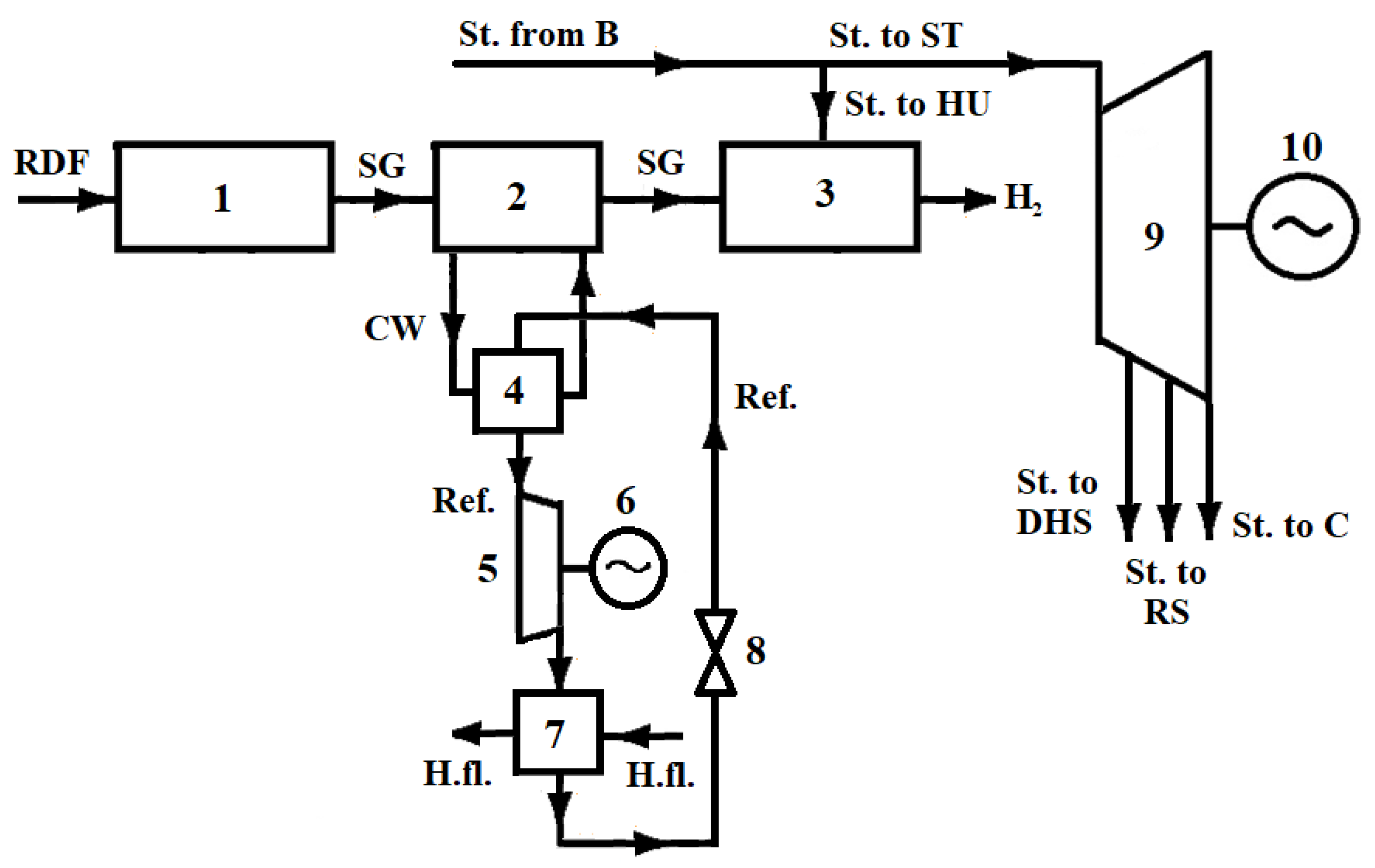
The synthesis gas generated during the gasification of RDF is cooled in a gas cooler, and then it is sent to a post-oxidation unit, in which the reaction of post-oxidation of CO to CO2 and the production of additional hydrogen due to the supply of steam are carried out. After that, hydrogen is extracted from H2 and CO2 mixture using the PSA method (Figure 2). To carry out this technological process, a cooling fluid for synthesis gas is required (water from the technical water supply system can be used) with steam for the additional oxidation of CO (steam from boiler units can be used). The heat released when cooling the synthesis gas can be removed to the environment or used by heat pumps.
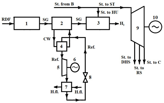
Figure 2.
Scheme of waste heat recovery in a hydrogen production unit. 1—gasifier; 2—gas cooler; 3—synthesis gas post-oxidation unit; 4—heat pump evaporator; 5—heat pump compressor; 6—electric drive; 7—heat pump condenser; 8—throttle; 9—steam turbine; 10—electric generator; St. from B—steam from the boiler unit; St. to ST—steam for the steam turbine; St. to HU—steam for the hydrogen production unit; St. to DHS—steam to the district heating system; St. to RS—steam for the steam turbine regenerative system; St. to C—steam to the condenser; SG—synthesis gas; H2—hydrogen; CW—cooling water; Ref.—coolant in the heat pump; and H.fl.—fluid heated in the heat pump.
The potential of waste heat that can be utilized in a hydrogen production unit is determined by the gas cooler heat balance:
where —the potential of waste heat, kW; —the average heat capacity of synthesis gas, kJ/(kg⸱°C); —the gasification process temperature, °C; —the cooled synthesis gas temperature, °C; —the cooling water mass flow rate, kg/s; —the cooling water heat capacity, kJ/(kg⸱°C); —the cooling water temperature at the gas cooler inlet, °C; and —the cooling water temperature at the gas cooler outlet, °C.
In Formula (2), the mass flow rate of synthesis gas produced in the gasifier is determined by the consumption of RDF and the mass content of ash formed during its thermal utilization. The average heat capacity of synthesis gas depends on the ratio of individual components and may vary due to the different morphological composition of the waste received for processing.
The generated hydrogen total mass flow rate is determined by the formula:
where —the generated hydrogen total mass flow rate, kg/s; —mass fraction of hydrogen extraction from the mixture using PSA; —mass flow rate of hydrogen in the synthesis gas, kg/s; and —mass flow rate of hydrogen formed during the oxidation of CO, kg/s.
The water vapor mass flow rate for the post-oxidation unit is determined by the formula:
where —the water vapor mass flow rate, kg/s; —the mass fraction of carbon monoxide in the synthesis gas.
In Formula (4), the coefficient of 0.642 is obtained based on the material balance of the chemical reaction of carbon dioxide oxidation, considering the molar masses of individual components [46].
Waste heat from a hydrogen generation unit can be used in technological processes of thermal power plants. Also, it can be used for heat supply to facilities, located on thermal power plants’ territory and external consumers. The choice of the optimal heat consumer from a heat pump depends on the parameters of the low-potential heat source, the type, design and working fluid (refrigerant) of the heat pump, the parameters and distance of the heat consumer, and the influence on the operating mode of thermal power plant equipment. This article discusses three possible directions for using heat from HP:
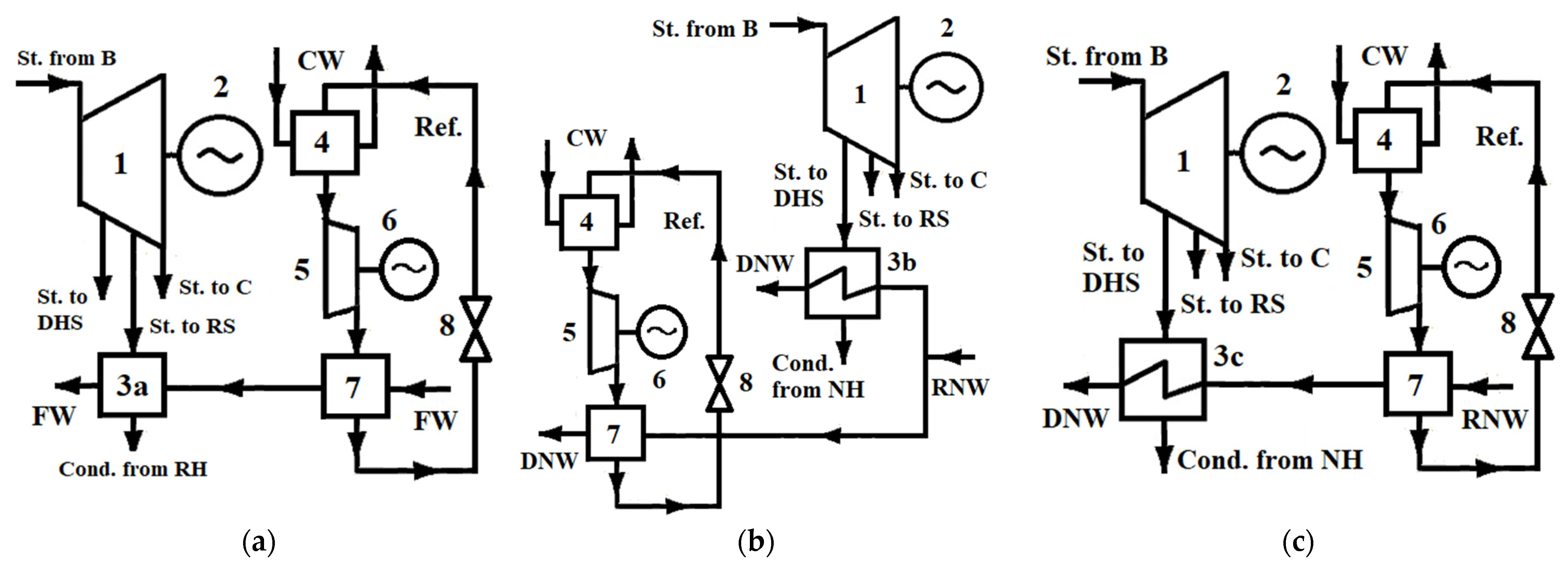
- for regenerative heating of feed water, with the installation of HPs in the fronts of low-pressure heaters and partial replacement of their loads (Figure 3a);
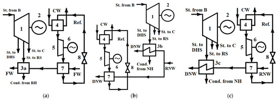 Figure 3. Schemes for using heat from a heat pump: (a) regenerative heating of feed water, (b) heating of network water in a parallel circuit, and (c) heating of network water in a sequential circuit. 1—steam turbine; 2—electric generator; 3a—regenerative feed water heater; 3b and 3c—network water heaters; 4—heat pump evaporator; 5—heat pump compressor; 6—electric drive; 7—heat pump condenser; 8—throttle; FW—feed water; Cond. from RH—condensate on discharge from the regenerative heater; RNW—return network water; DNW—direct network water; and Cond. from NH—condensate on the drain from the network heater.
 - for external or internal heat supplies, with the installation of HP-bypassing network heaters (parallel circuit) with an increase in heat supply (Figure 3b);
- for heat supplies to external or internal consumers, with the installation of HPs in the fronts of network heaters (sequential circuit) with an increase in heat supply (Figure 3c).
One of the main indicators used to assess the economic efficiency of a technical solution is net present value, determined by the formula:
where —the cash flow of the relevant year t, EUR; —the HP life cycle; —the discount rate; —the cash proceeds by the sale of thermal energy in the relevant year t, EUR; —capital investments in the relevant year t, EUR; and —the expenditures in the relevant year t, EUR.
From Formula (5), it follows that if the full volume of capital investments in HP is carried out within one calendar year, the annual money flows from the implementation of the circuit solution will be positive if the following condition is met:
Then, in the most general case, to analyze the annual cash flows from the HP used in a hydrogen production unit at a thermal power plant, the following expression can be used:
where —the change in electricity supply from thermal power plants when using HP, MWh; —electricity price, EUR/MWh; —change in the thermal plants heat supply when using HP, MWh; —price of thermal energy, EUR/MWh; —change in the consumption of reference fuel at thermal power plants when using HP, t ref.f.; and —price of the reference fuel, EUR/t ref.f.
The use of heat from the HP for regenerative heating of feed water makes it possible to increase the electrical power of the steam turbine (by reducing the steam consumption in the regenerative extraction) while maintaining constant fuel consumption and heat output. However, this circuit solution will provide positive cash flows only if the increase in turbine power compensates for the energy costs of driving the HP compressor (8).
where —the change in the electrical power of the turbine with a decrease in steam flow into the regenerative extraction, MW; and —electric power consumed by the HP compressor, MW.
The use of heat from the heat pump to supply heat to an external or internal consumer makes it possible to increase both the electrical power of the steam turbine (by reducing the steam consumption in the heating system) and the thermal power of the thermal power plant (by releasing additional heat from the heat pump), with constant fuel consumption. The efficiency of this circuit solution will be influenced not only by changes in the volumes of electricity and heat produced by thermal power plants but also by the ratio of regional tariffs for energy resources (8).
The potential additional economic benefit from recycling the waste heat of a hydrogen production plant into a heat pump is a reduction in water-use costs. When cooling the synthesis gas before the post-oxidation unit, water can be used from the technical water supply system (WSS) of the thermal power plant, which will then be discharged either into the environment (direct-flow WSS) or into a cooling device—a cooling tower or cooling pond (reverse-flow WSS). The amount of reduction in costs for water use at thermal power plants when using heat pumps can be determined taking into account Formula (2):
where —the share of water discharged from the WSS; and —tariff for water use for thermal power plants, EUR/m3.
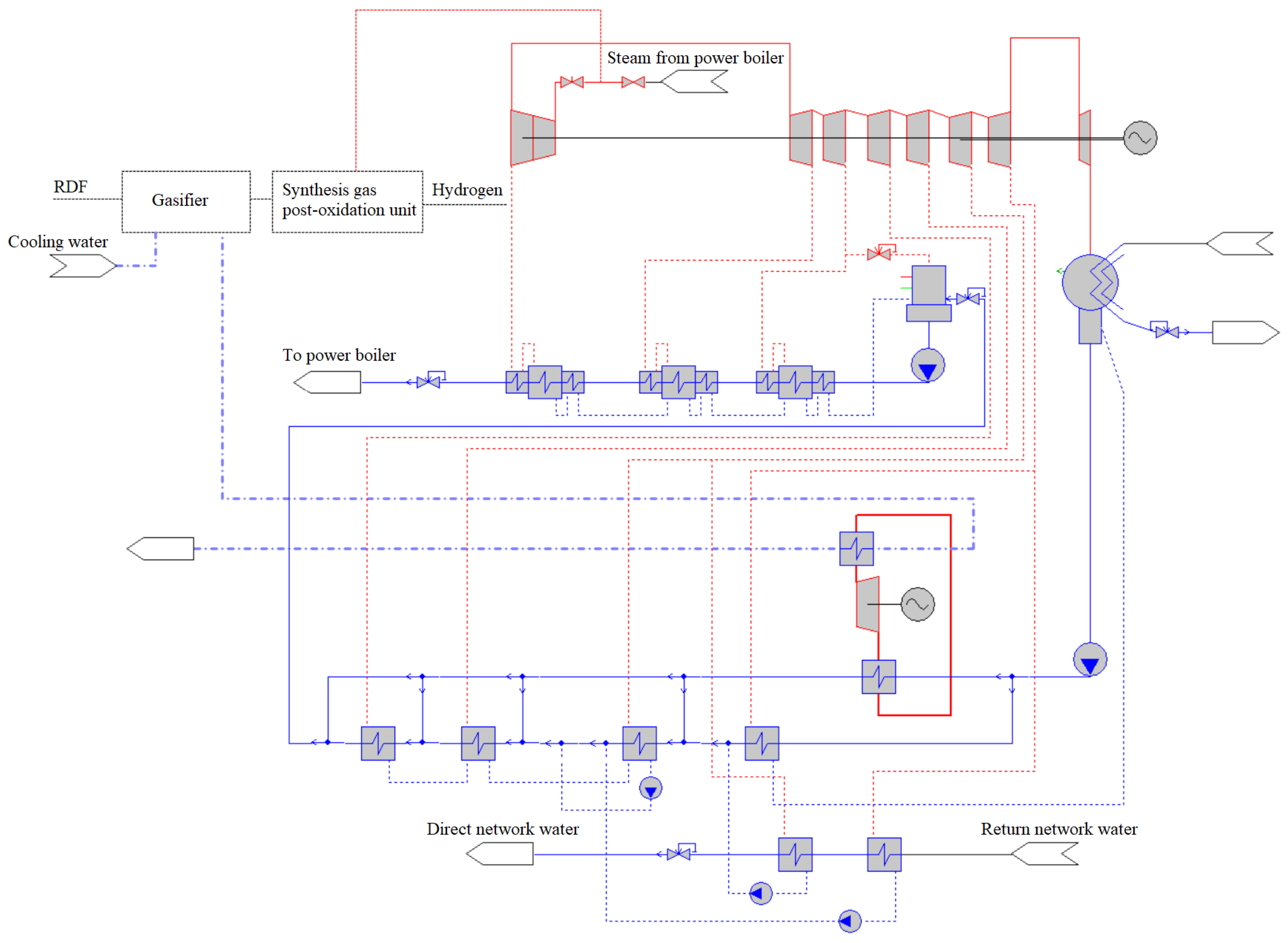
To analyze the influence of a heat pump that utilizes waste heat during hydrogen production on the technical–economic indicators of thermal power plants, the thermal diagram of a combined heat and power plant (CHPP) based on a steam power unit with a steam turbine of the T-100/120-130-3 type, and a boiler unit of the TGM-96B type was considered for the conditions of St. Petersburg. When conducting the study, methods of mathematical modeling of thermal power plant operating modes were used in the CAD system “United Cycle” (“M Systems” company, Saint Petersburg, Russia). The characteristics and indicators of the vapor compression HP was made in the open-accessprogram “CoolPack” (Department of Mechanical Engineering, Kongens Lyngby, Denmark). The calculation diagram of the mathematical model of the T-100/120-130-3 turbine with the integration of a HP for heating feed and network water is shown in Figure 4.

Figure 4.
Calculation diagram of the mathematical model of the T-100/120-130-3 turbine with a unit for the production of hydrogen from MSW and a heat pump.
Initial data accepted for calculating the main parameters of the unit for the production of hydrogen from MSW at thermal power plants:
- The amount of waste sent for processing is determined, taking into account the data of the territorial scheme for the management of production and consumption waste [47]—for the conditions of St. Petersburg, it is 2.4 million tons of MSW per year;
- The percentage of extraction from MSW of suitable fractions for gasification (for the conditions of St. Petersburg, it is accepted at the level of 30%);
- RDF consumption is assumed to be in the range of 10–100 t/h;
- Mass content of ash in the composition of gasification products (accepted at 10%);
- The volumetric hydrogen content in the synthesis gas is assumed to be 25, 50, and 75% due to the different morphological composition of MSW supplied for processing;
- Temperature of the gasification process ( = 850 °C);
- Cooled synthesis gas temperature ( = 450 °C);
- The composition and characteristics of the synthesis gas components are presented in Table 2 [46];
Table 2. Composition and characteristics of the components of synthesis gas obtained from MSW.
- Heat capacity of cooling water ( = 4.19 kJ/kg °C);
- Temperature of cooling water entering the gas cooler ( = 20 °C);
- Temperature of cooling water at the outlet of the gas cooler in a circuit without a heat pump ( = 30 °C);
- Fraction of hydrogen extraction from a mixture using PSA ( = 0.99).
Initial data accepted for calculating the main parameters of the unit for the production of hydrogen from MSW at thermal power plants (common for circuits a–c, Figure 3):
- Temperature of cooling water at the outlet of the HP ( = 20 °C);
- Temperature of cooling water at the inlet of the HP ( = 30 °C);
- Temperature difference in the evaporator and condenser of HP ( = 5 °C).
Initial data accepted for calculating the efficiency of using HP for waste heat recovery in the unit to produce hydrogen from MSW at thermal power plants (common for circuits a–c, Figure 3):
- Operating mode of the main power equipment: boiler thermal power—nominal; fuel consumption is constant; diaphragm is closed—maximum heat output; and pressure in the condenser—constant 0.04 kgf/cm2;
- Weighted average price on the day-ahead market of the wholesale electricity market of the Russian Federation for the Organization for Economic Cooperation of the North-West at the beginning of 2021—12.68 EUR/MWh [48];
- Average price of heat producers (CHP) in the Russian Federation at the beginning of 2021 is 9.55 EUR/MWh [49];
- Average price for fuel equivalent in the Russian Federation at the beginning of 2022 at thermal power plants is 39.58 EUR/t ref.f. [49];
- The rate of payment for the withdrawal of water resources in 2022 for thermal power plants with direct-flow water supply systems is 774 rubles/thous. m3 for thermal power plants with reverse-flow water supply systems 6.06 EUR/thous. m3 [50].
3. Results
3.1. Calculation of the Main Parameters of the Unit for the Hydrogen Production from MSW at Thermal Power Plants
The most important factors that can radically affect the payback of the unit for the hydrogen production from MSW at thermal power plants include:
- The amount of hydrogen generated by the unit;
- Maximum amount of MSW processed by the unit;
- Degree of influence on key TPPs’ technical–economic indicators.
It should be taken into account that the synthesis gas obtained from MSW, due to the heterogeneity of the morphological composition of the waste supplied for processing, is characterized by a fairly wide range of the ratio of H2 and CO. On average, the concentration of hydrogen in the volume of synthesis gas can vary from 25 to 75%, which will have a significant impact on the main characteristics of the unit for the hydrogen production from MSW. Figure 5 and in Table 3 presents the results of calculating the main indicators of the unit, depending on the consumption of RDF and the H2 content in the synthesis gas. Figure 5 shows the increasing influence of the morphological composition of waste on the consumption of generated hydrogen as the consumption of processed MSW increases.
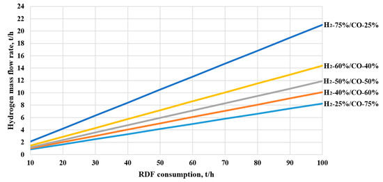
Figure 5.
Mass flow rate of generated hydrogen depending on RDF fuel consumption and ratio of H2 and CO extraction.
Table 3.
Main indicators of the unit for converting MSW into hydrogen.
The main limitation on the amount of waste processed in a hydrogen production plant at a thermal power plant can be the performance of steam-generating equipment. Calculations have shown that when the RDF consumption changes from 10 t/h to 100 t/h, the need for a hydrogen production in water vapor to carry out the carbon monoxide oxidation reaction will be from 5.64 to 56.4 t/h. Taking into account the fact that the nominal steam consumption from a TGM-96 type steam boiler is 480 t/h, for a power unit with a T-100/120-130-3 turbine, there are no direct restrictions on the productivity of steam generating equipment.
However, the steam boiler must provide the flow of working fluid to the turbine in the amount necessary to maintain operation within the control range. At a maximum load of 100–110 MW, the steam consumption for a turbine of this type is 480–485 t/h, accordingly, the extraction of steam for a hydrogen production plant will entail a decrease in the electrical and thermal power of the equipment (Table 4). Calculations have shown that the most significant factor influencing the undersupply of electrical and thermal energy from thermal power plants, as a result of the operation of the installation for converting MSW into hydrogen, is the processed amount of MSW (1.0–12.0 MW and from 3.5–31.4 MW), whereas the morphological composition of the waste does not have such a significant effect (0.2–1.0 MW and 0.6–2.3 MW).
Table 4.
Main indicators of the unit for converting MSW into hydrogen.
Based on the foregoing, we can conclude that the determination of the MSW consumption sent for processing in a hydrogen production unit located at a thermal power plant should be carried out on the basis of optimization, taking into account the expected morphological composition of the waste, the economically justified volume of hydrogen production, the permissible level of reduction in electrical and thermal energyof a turbine.
3.2. Calculation of the Main Parameters of a Heat Pump That Utilizes Waste Heat from the Unit for the Hydrogen Production from MSW at Thermal Power Plants
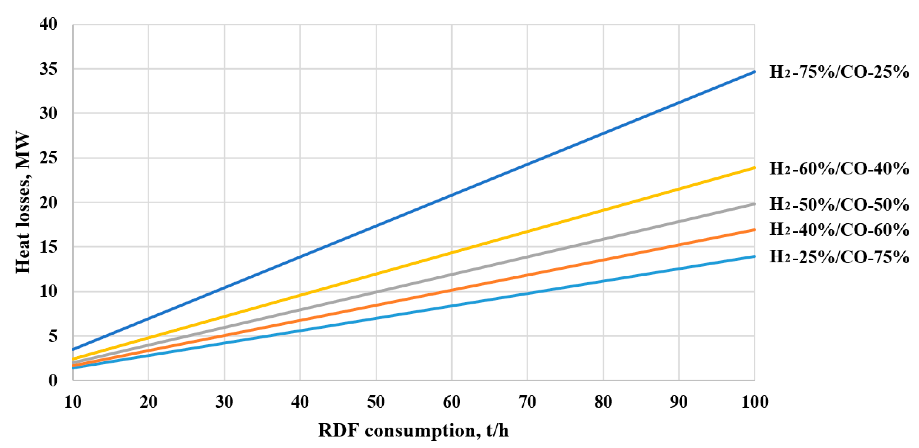
The gasification process of MSW is carried out at a temperature of about 850 °C, and the target temperature of the synthesis gas before the post-oxidation unit (Figure 2) is 450 °C. The heat removed in the synthesis gas cooler can be used in the heat pump to increase the efficiency of the unit. Figure 6 presents the results of an estimated calculation of heat losses during cooling of synthesis gas. Figure 6 shows that when processing a large amount of MSW into hydrogen, a lot of heat can be obtained to supply heat to the consumer. For example, with an RDF consumption of 100 t/h and HP energy conversion coefficient equal to 3, the heat output from the HP will be 52.5 MW (of which 35 MW is due to the utilization of low-potential heat in the HP evaporator (Figure 6), and 17.5 MW due to increased pressure of a refrigerant in the HP compressor).
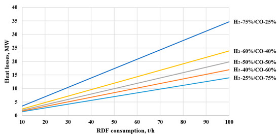
Figure 6.
Heat losses in the unit for converting MSW into hydrogen.
The direction of use of heat from the heat pump has a significant impact on the efficiency indicators of the heat pump, as well as on the degree of its influence on the key technical–economic indicators of the thermal power plant. Table 5 presents the results of calculating technical–economic indicators of the heat pump that utilizes waste heat in a unit for the production of hydrogen from MSW (RDF fuel consumption is 90 t/h). Regenerative heating of feed water and heat supply to external consumers were considered as the main areas for using heat from HP. The calculations showed that, from the point of view of energy efficiency, the most promising is the heating of network water according to the scheme of sequential connections of HPs and network heaters. Also, from the key performance indicators’ point of view, the use of HPs for heating feed water before low-pressure heaters has acceptable efficiency. However, this circuit solution is characterized by the impossibility of fully using the potential of waste heat (about 2–7% of the total amount released during cooling of synthesis gas).
Table 5.
Main indicators of a heat pump in the unit for the hydrogen production from MSW.
When heating network water in a heating element both in series and in parallel, it becomes possible to completely involve low-potential heat in the energy balance of the thermal power plant. It should also be noted that the morphological composition of the waste has virtually no effect on the efficiency of the HP used in the MSW processing unit but significantly affects its thermal power and energy consumption.
Reducing the amount of waste processed in a hydrogen production unit leads to a decrease in the thermal power of the HP, as well as its energy consumption. For circuit solutions that involve heating feed water and network water (parallel connection of network heaters and HP), the efficiency of the HP is also reduced. However, when heating network water according to a scheme with a sequential connection of network heaters and HP, the efficiency of the HP increases, with a decrease in the consumption of RDF fuel, due to a decrease in the temperature at its outlet (a decrease in the difference between the temperature of evaporation and condensation of the refrigerant).
3.3. Analysis of the Influence of a Heat Pump That Utilizes Waste Heat in the Unit for the Hydrogen Production from MSW on the Technical and Economic Indicators of Thermal Power Plants
The integration of the hydrogen production unit will have a significant impact on key technical–economic indicators of thermal power plants, primarily due to the need to take steam to the post-oxidation unit (up to 12% of the boiler’s nominal steam output). Table 6 presents the results of calculating the main parameters of a thermal power plant, with the unit for converting MSW into hydrogen integrated into the thermal circuit. The calculation was carried out under the condition of constant steam flow from the boiler plant, and the extraction of part of it for the needs of the post-oxidation unit in front of the turbine.
Table 6.
Indicators of TPP with the hydrogen production from MSW.
From Table 6, it can be seen that, as the amount of processed waste increases, not only the volume of supply of electrical and thermal energy from the turbine power unit decreases but also the efficiency of fuel use of thermal power plants. However, it should be taken into account that the calculations performed were aimed at assessing thermal power plants as a cogeneration facility. When moving to the analysis of thermal power plants with an installation for converting MSW into hydrogen, as an object of trigeneration, i.e., when hydrogen is given, the status of an equivalent product, along with electricity and heat, and the approach to calculating the efficiency of fuel use should change.
The integration of a system for recycling waste heat from synthesis gas using HP should help partially compensate for the deterioration of the thermal power plant’s technical–economic indicators and increase its thermal efficiency. Table 7 presents the results of calculating the influence of key technical–economic indicators of the thermal power plant on the utilization of waste low-potential heat using heat pumps. The calculation was carried out under the condition of constant steam mass flow rate from the power boiler for the unit processing 90 t/h of RDF.
Table 7.
TPP technical–economic indicators with the unit for producing hydrogen from MSW and recycling waste heat.
Calculations showed that the nature of the influence of HP on the key technical-economic indicaors of TPP is determined by the choice of a circuit design. Thus, when using HP to heat network water, the volume of electricity generation will be further reduced relative to schemes without HP (due to additional costs for driving the HP compressor), with an increase in the total volume of heat supplied to the consumer. At the same time, a parallel circuit for connecting HP and network heaters is characterized by higher thermal efficiency and an increase in heat output, whereas a sequential circuit allows for a higher level of electricity generation. It should be considered that the parallel scheme will be effective in the case of an increase in the mass flow rate of network water through the district heating system, and the results obtained are valid for a given mass flow rate of network water through the HP and network heaters. In addition, when implementing a sequential circuit with a high-power HP, which provides significant heating of the network water in front of the network heaters, the coefficient of underproduction of electricity will increase.
The final decision on the optimal circuit design should be made based on technical and economic calculations, taking into account regional prices for energy resources and operating modes of thermal power plants.
3.4. Analysis of the Influence of a Heat Pump That Utilizes Waste Heat in a Unit for the Hydrogen Production from MSW on the Marginal Profit of a Thermal Power Plant
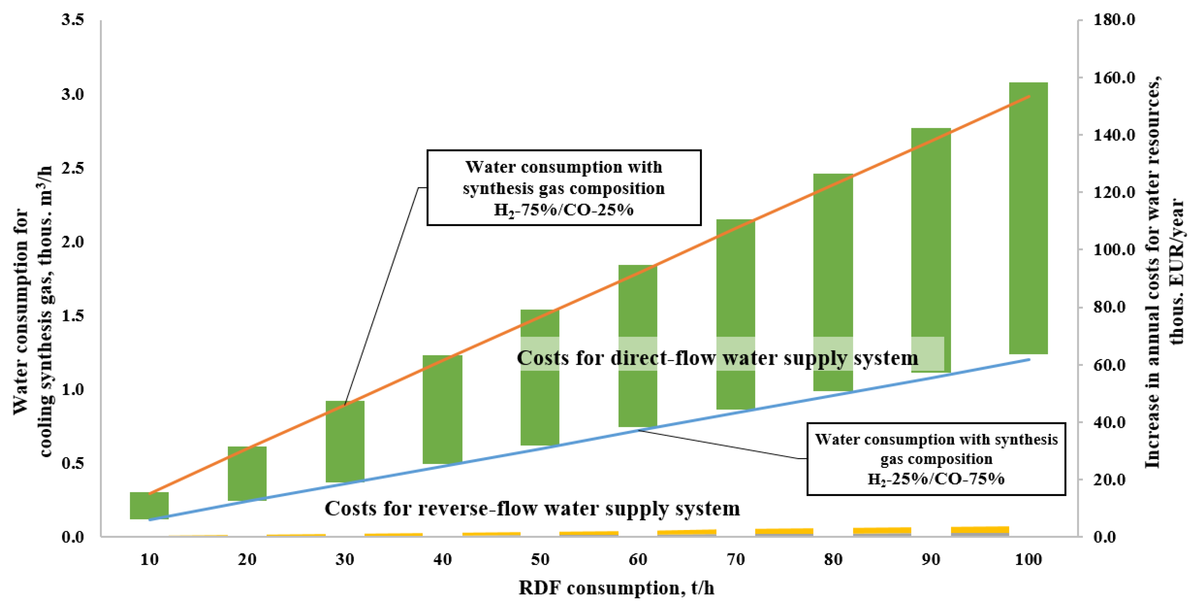
The integration of a unit for the production of hydrogen from MSW into the thermal circuit of thermal power plants leads to an increase in the cost of purchasing water for the needs of cooling equipment and mechanisms. In this case, the type of a water supply system will have a significant impact. Figure 7 presents the results of an estimated calculation of the dynamics of the increase in average hourly volumes of water resource consumption and the amount of annual fees due to the processing of waste into hydrogen at thermal power plants, with various water supply systems located in St. Petersburg.
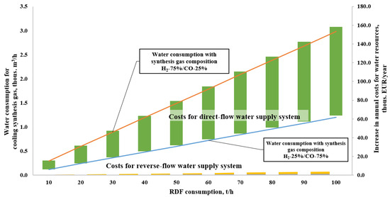
Figure 7.
Dynamics of the increase in cooling water consumption and water intake cost for thermal power plants with the unit for converting MSW into hydrogen.
For thermal power plants with a reverse-flow WSS, an increase in water consumption for cooling synthesis gas will not have a noticeable impact on total costs and, consequently, on the key performance indicators of their activities. Accordingly, in calculating the economic effect of integrating a plant for the hydrogen production from MSW, this factor may not be taken into account. However, for TPPs with direct-flow WSS, the increment in annual costs associated with the consumption of water resources from surface sources can reach 17 million rubles/year (for the conditions of St. Petersburg). In this case, the effect of changes in the volume of water use of TPPs must be considered. In addition, the price of water use varies significantly by region and exceeds the price of water use from the river Neva by 2 times for a few surface sources (for example, for some rivers of the North Caucasus economic region of the Russian Federation), which will lead to a proportional increase in water use costs for thermal power plants with a similar composition of equipment but located in a different region.
Table 8 presents the results of calculating the marginal profit for thermal power plants with and without a MSW processing unit, as well as several options for circuit solutions for recycling waste heat using HP, taking into account the morphological composition of the waste and the capacity of the hydrogen production plant.
Table 8.
Impact of a thermal power plant design with a hydrogen production unit on marginal profit.
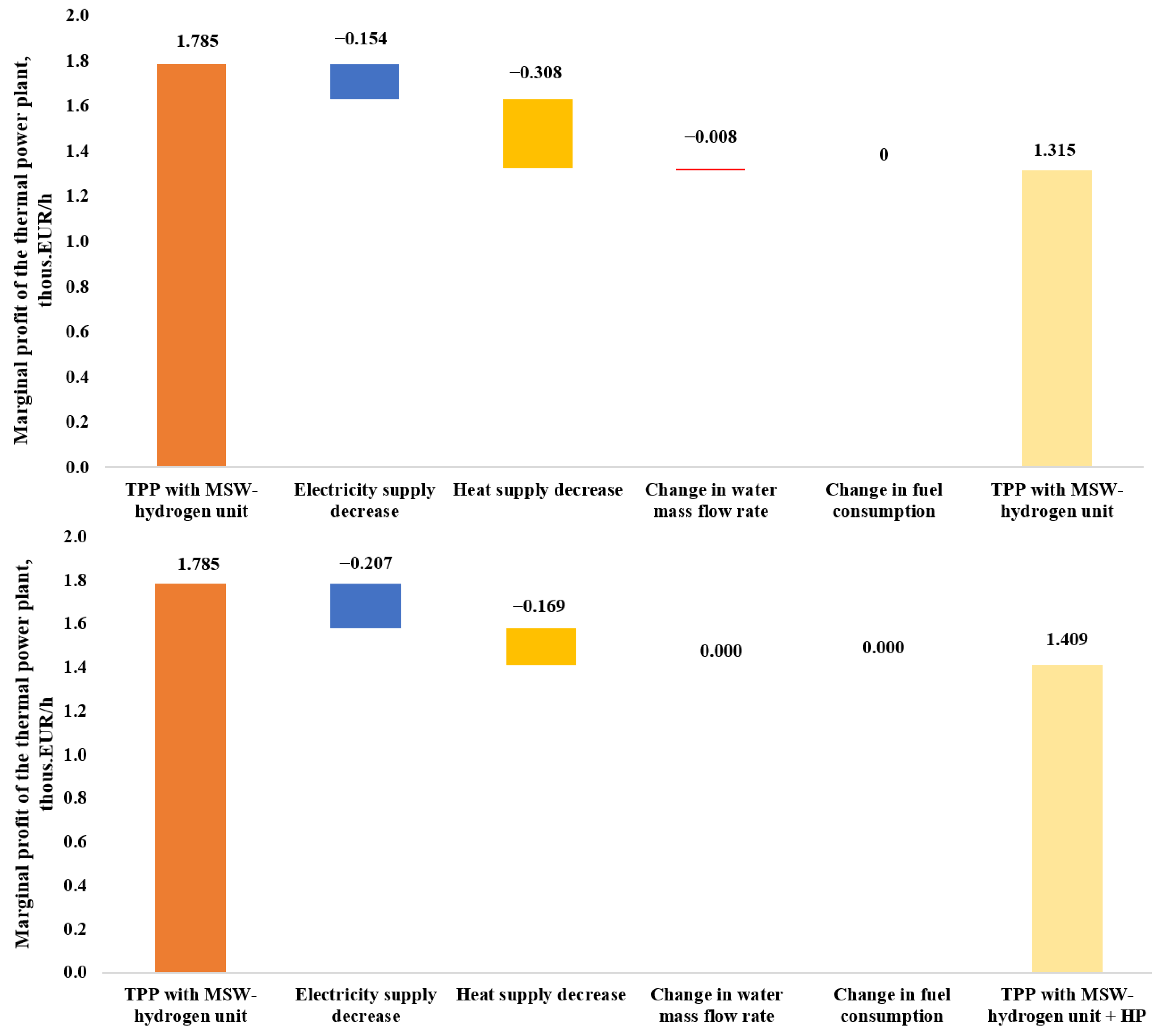
Calculations showed that the organization of processing waste into hydrogen at TPPs, in any case, will lead to a decrease in the marginal profit from sales of electricity and heat (up to 26%), due to a decrease in supply volumes, due to the need to organize steam extraction for the post-oxidation unit. The use of HPs will partially compensate the negative impact of the hydrogen production unit (Figure 8), due to an increase in the volume of heat supply. However, this will be accompanied by a decrease in the amount of electricity supplied to the market due to an increase in electrical own needs (to drive the HP compressor). For example, when processing 90 t/h of RDF and the hydrogen content in the synthesis gas at the level of 25%, for the market conditions of St. Petersburg, the reduction in marginal profit will reach 26% (with electricity supply of 99.3 MWh and heat supply 172.7 MWh). Utilization of waste heat will partially offset the negative effect and the reduction in marginal profit will already be 10.6% (with electricity supply of 89.4 MWh and heat supply of 214.3 MWh). It should also be considered that the ratio of regional energy prices will have a significant impact on the marginal profit of thermal power plants.

Figure 8.
Factor analysis of changes in the marginal profit of thermal power plants when using the unit for converting MSW into hydrogen with HP.
The morphological composition of processed waste has a significant impact on the potential of HPs in terms of compensating for the negative impact of a hydrogen production plant on the marginal profit of thermal power plants. Increasing the percentage of hydrogen content in synthesis gas can increase the positive effect of low-potential heat utilization by more than 10%.
Reducing the amount of MSW processed in a hydrogen production unit leads to minimizing the negative impact of steam extraction at the post-oxidation unit on the marginal profit of thermal power plants from the sale of electricity and heat (Table 8). Thus, for RDF consumption of 10 t/h, the reduction in marginal profit, regardless of the selected circuit design and synthesis gas composition, will be no more than 1.6–3.3%.
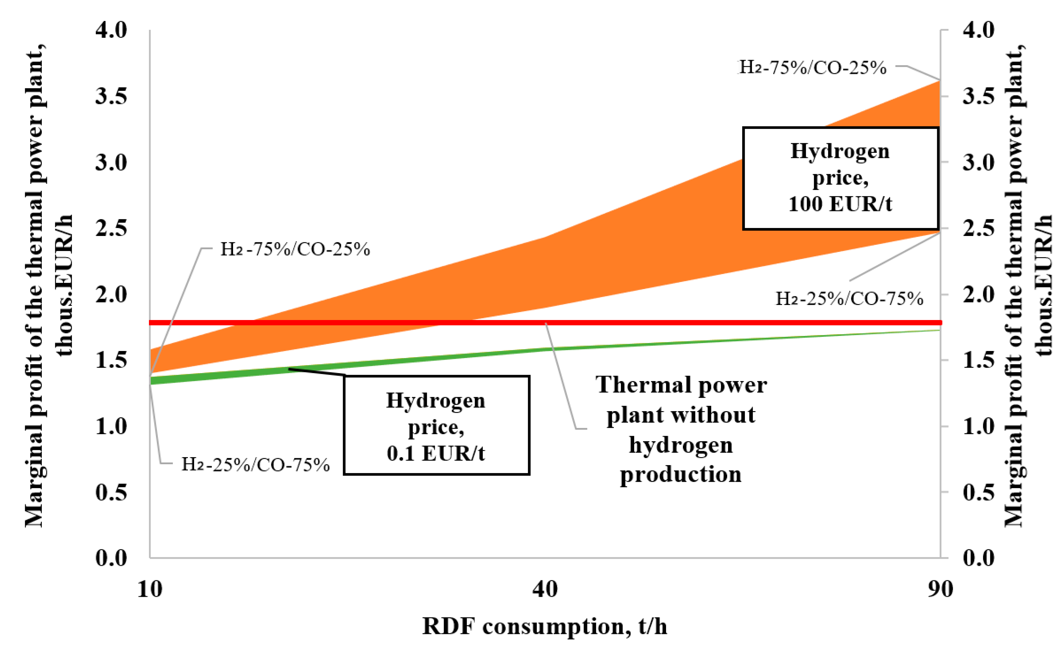
The economics of a thermal power plant with a hydrogen production unit will be significantly influenced by its market price (Figure 9). If we consider hydrogen as an equivalent product produced at thermal power plants, an increase in the consumption of RDF will allow not only to achieve the previous level of marginal profit but also to exceed it. Analyzing the data presented in Figure 9, we can conclude that, for each thermal power plant with a unit for processing MSW of a certain morphological composition, at a given level of hydrogen prices, the minimum consumption of RDF can be found, providing an acceptable level of marginal profit. So, for the TPP equipment under consideration, synthesis gas composition is H2-75%/CO-25%, hydrogen price is 10 EUR/t, and the minimum consumption of RDF fuel is 60 t/h. However, when the hydrogen content in the synthesis gas is reduced to 25%, the minimum consumption of RDF will increase to 85 t/h.
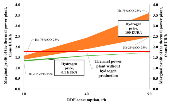
Figure 9.
Analysis of the impact of the price of hydrogen on the marginal profit of thermal power plants with a unit for converting MSW into hydrogen.
4. Discussion
The large-scale integration of modern technologies at the industry level, which ensure the efficient use of natural resources, as well as contribute to an increase in the level of waste disposal consumption, is the most effective direction for achieving the key goals of state policy in the field of environmental safety. This can be confirmed by serious scientific research currently ongoing around the world aimed at the development, analysis, economic justification, and improvement of low-carbon and resource-saving technologies that help reduce the negative impact on the environment.
The enterprises of the Russian fuel and energy complex have significant potential in terms of hydrogen production. This is supported, for example, by the fact that the average installed capacity utilization factor of TPP equipment in the UES of Russia does not exceed 55% [51]. Excess electrical capacity can be used in the process of generating carbon-free fuel, which can then be involved in the country’s fuel and energy balance or exported.
However, it should be noted that despite the strategic importance of carbon-free energy for the entire world community, its widespread distribution will continue to be constrained by relatively low prices, simplicity, and a significant base for the practical application of traditional technologies based on the use of fossil fuels. This situation will continue until more environmentally friendly equipment reaches an acceptable level of efficiency or a way is found to combine it with existing power plants with the prospect of their further replacement.
In addition, it is necessary to develop a regulatory framework in the field of organizing the operation of energy complexes based on thermal power plants, designed to simultaneously solve the problems of electricity and heat supply, waste disposal, and hydrogen production at the regional level. Also, issues related to the development of a methodology for a comprehensive analysis of the impact of such complexes on the ecology of the region need to be addressed.
In this article, the authors tried, on the basis of a technical and economic analysis of circuit solutions, to evaluate the rationality of using technologies for waste disposal and hydrogen production at thermal power plants. The results presented in the article can be used in the development of a methodological basis for further research in the field of hydrogen production at thermal power plants, as well as in the design of circuit solutions for similar enterprises.
It should be taken into account that the calculations of the economic indicators of TPPs were carried out without assessing the income component due to the sale of hydrogen, as well as various kinds of incentive allowances associated with state policy in the field. The presentation of hydrogen as an equivalent product will require consideration of the operation of TPPs in the trigeneration mode, which means the creation and approval of a specialized methodology for dividing fuel costs. Attempts to develop such a technique are presented in the article [29], but they concern the production of hydrogen at thermal power plants by the method of steam reforming of methane. The issue of the need to develop a system of state incentives for hydrogen production was considered in the article [9]; however, the results refer to the technology of hydrogen production by electrolysis in the conditions of the Croatian power system.
It should be noted that the calculations presented in this article were carried out for the nominal mode without taking into account the need to operate the main power equipment within the regulatory range in the electricity market, as well as from the supply of thermal energy to the consumer within the volumes and temperature schedule established by the contract. The issues of a more detailed analysis of the operating modes of TPPs with a plant to produce hydrogen from MSW and the utilization of waste heat of synthesis gas in HPs with various circuit solutions are an area for further research as part of the development of a theoretical framework for the introduction of low-carbon technologies in the Russian energy sector.
5. Conclusions
- The use of energy complexes, including thermal power plants, plants for the production of hydrogen from municipal solid waste and heat pumps, is a promising direction in the development of the fuel and energy complex, contributing to the solution of a number of problems related to electricity and heat supply to large industrial and municipal consumers, increasing the level of utilization of production and consumption waste, hydrogen production for various industries, as well as increasing the efficiency of using natural resources.
- The unit for the conversion of MSW into non-carbon fuel, by gasification with pressure swing adsorption, is capable of producing hydrogen in an amount of 0.8 to 21.0 t/h while processing RDF fuel in an amount of 10 to 100 t/h, respectively. In this case, the mass flow rate of vapor for the implementation of the additional oxidation of CO will be from 5.6 to 47.5 t/h.
- The integration of a unit to produce hydrogen from MSW into the thermal circuit of a thermal power plant will provide the required amount of vapor but will lead to a deterioration in the technical-economic indicators of the plant. So, for a TPP based on an STU with a T-100/120-130-3 turbine and a TGM-96B steam boiler, provided that the steam output of the boiler is maintained at the nominal level, the decrease in the electric power of the TPP will vary within 1.1–12.2 MW (0.97–10.95%), and thermal is 3–32.2 MW (1.47–15.72%), depending on the capacity of the hydrogen production unit and the morphological composition of the waste. At the same time, the fuel efficiency of TPPs will significantly decrease (an increase in the specific consumption of reference fuel will be from 5.8 to 57.6 ref.f./kWh or from 5.34 to 53.05%, respectively).
- The production of hydrogen from MSW at TPPs will also require an increase in the consumption of cooling water to reduce the parameters of synthesis gas (from 119.9 to 2980.8 t/h), which, in turn, will entail an increase in payment for water use. Depending on the type of service water supply system, the increase in payment for water use for TPPs will be 0.1–2.8 thous. EUR/year with a reverse-flow WSS, and 6–158 thous. EUR/year with a direct-flow WSS.
- Utilization of waste heat released during the cooling of synthesis gas with the help of HPs will partially compensate for the deterioration of the key technical–economic indicators of TPPs and ensure that the payment for water use remains at the same level. For TPPs based on STU with a T-100/120-130-3 turbine and a TGM-96B steam boiler, when HP is used to heat network water, the reduction in electricity generation from TPPs will be 21.9–35.6 MW (19.64–31.94%)—energy costs for the HP compressor drive, with an increase in heat output to 29.8 MW (14.2%). At the same time, the level of efficiency of TPP fuel use will increase due to the involvement of low-potential heat in the fuel and energy balance.
- In this work, three possible areas for using heat from HP were examined: for regenerative heating of feed water, as well as for external or internal heat supply using a parallel and sequential connection scheme. The greatest efficiency was shown by the circuit with parallel connection of the HP (the reduction in specific fuel consumption for the supply of electricity was up to 32%), and the sequential circuit the reduction in the specific consumption for supply of electricity was up to 14.2%. The circuit with using HP for regenerative heating showed the least efficiency (reduction in specific fuel consumption for electricity supply—up to 1.2%).
- The use of a solid-waste recycling unit at TPPs will lead to a decrease in the marginal income from the sale of electricity and heat. This decrease can be partially compensated by supplying an additional amount of heat from heat pumps; however, the potential of this measure will be significantly affected by regional energy prices. For TPPs based on STU with a T-100/120-130-3 turbine and a TGM-96B steam boiler, when HP is used to heat network water, the reduction in marginal income due to the MSW–hydrogen unit will be estimated at 0.47 thous. EUR/h. With the utilization of waste heat from synthesis gas, the reduction in marginal income due to the MSW–hydrogen plant will amount to 0.38 thous. EUR/h.
- A significant factor influencing the efficiency of a TPP with a municipal solid waste processing unit is the price of hydrogen. Its increase ensures an increase in the total marginal profit and compensation for losses from undersupply of electricity and heat. However, for a given price level, there is a minimum amount of MSW converted into hydrogen, corresponding to the condition of not reducing the efficiency of a TPP. For thermal power plants based on STU with a T-100/120-130-3 turbine and a TGM-96B steam boiler, at a hydrogen price of 10 EUR/t, depending on the morphological composition of MSW, the minimum consumption of RDF fuel varies from 60 to 85 t/h.
Author Contributions
Conceptualization, M.T. and D.K.; methodology, M.T.; software, I.A.; validation, D.K. and D.T.; formal analysis, D.T. and K.K.; investigation, D.T.; resources, I.V.; data curation, I.V.; writing—original draft preparation, M.T.; writing—review and editing, D.K. and K.K.; visualization, K.K.; supervision, M.T. and I.A.; project administration, I.A.; funding acquisition, I.V. All authors have read and agreed to the published version of the manuscript.
Funding
The research was funded by the Ministry of Science and Higher Education of the Russian Federation under the strategic academic leadership program “Priority 2030” (Agreement 075-15-2023-380 dated 20 February 2023).
Institutional Review Board Statement
Not applicable.
Informed Consent Statement
Not applicable.
Data Availability Statement
The data are not publicly available due to privacy considerations.
Conflicts of Interest
The authors declare no conflict of interest.
References
- Government of the Russian Federation. Environmental Safety Strategy of the Russian Federation for the Period Till 2025. Available online: http://government.ru/docs/all/111285/ (accessed on 12 September 2023).
- Rosprirodnadzor. Federal Service for Supervision of Environmental Management of the Russian Federation. Available online: https://rpn.gov.ru (accessed on 12 September 2023).
- Rosstat. Federal State Statistics Service of the Russian Federation. Available online: https://rosstat.gov.ru (accessed on 12 September 2023).
- Yezhova, A.A.; Androsova, N.K. Comparative analysis of foreign and Russian experience in the field of solid household waste management. Proc. Saratov Univ. New Ser. Chem. Ser. Biol. Ecol. 2013, 3, 94–98. (In Russian) [Google Scholar]
- Kalyutik, A.A.; Treshchev, D.A.; Pozdeeva, D.L. Recycling municipal solid waste at power-and-heating plants of St. Petersburg. St. Petersburg Polytech. Univ. J. Eng. Sci. Technol. 2019, 25, 59–70. [Google Scholar] [CrossRef]
- Ministry of Energy of the Russian Federation. Energy Strategy of the Russian Federation for the Period Till 2035. Available online: https://minenergo.gov.ru/node/1026 (accessed on 12 September 2023).
- Van Leeuwen, C.; Mulder, M. Power-to-gas in electricity markets dominated by renewables. Appl. Energy 2018, 232, 258–272. [Google Scholar] [CrossRef]
- Liu, B.; Yu, X.; Shi, W.; Shen, Y.; Zhang, D.; Tang, Z. Two-stage VSA/PSA for capturing carbon dioxide (CO2) and producing hydrogen (H2) from steam-methane reforming gas. Int. J. Hydrogen Energy 2020, 45, 24870–24882. Available online: https://www.sciencedirect.com/science/article/abs/pii/S0360319920324551?via%3Dihub (accessed on 12 September 2023). [CrossRef]
- Dumančić, A.; Vlahinić Lenz, N.; Majstrović, G. Can Hydrogen Production Be Economically Viable on the Existing Gas-Fired Power Plant Location? New Empirical Evidence. Energies 2023, 16, 3737. [Google Scholar] [CrossRef]
- Kaplan, R.; Kopacz, M. Economic Conditions for Developing Hydrogen Production Based on Coal Gasification with Carbon Capture and Storage in Poland. Energies 2020, 13, 5074. [Google Scholar] [CrossRef]
- Gonzalez-Diaz, A.; Sánchez Ladrón de Guevara, J.C.; Jiang, L.; Gonzalez-Diaz, M.O.; Díaz-Herrera, P.; Font-Palma, C. Techno-Environmental Analysis of the Use of Green Hydrogen for Cogeneration from the Gasification of Wood and Fuel Cell. Sustainability 2021, 13, 3232. [Google Scholar] [CrossRef]
- Guban, D.; Muritala, I.K.; Roeb, M.; Sattler, C. Assessment of sustainable high temperature hydrogen production technologies. Int. J. Hydrogen Energy 2020, 45, 26156–26165. [Google Scholar] [CrossRef]
- Beschkov, V.; Ganev, E. Perspectives on the Development of Technologies for Hydrogen as a Carrier of Sustainable Energy. Energies 2023, 16, 6108. [Google Scholar] [CrossRef]
- Fu, P.; Pudjianto, D.; Zhang, X.; Strbac, G. Integration of Hydrogen into Multi-Energy Systems Optimisation. Energies 2020, 13, 1606. [Google Scholar] [CrossRef]
- Mikovits, C.; Wetterlund, E.; Wehrle, S.; Baumgartner, J.; Schmidt, J. Stronger together: Multi-annual variability of hydrogen production supported by wind power in Sweden. Appl. Energy 2021, 282, 116082. [Google Scholar] [CrossRef]
- Schiebahn, S.; Grube, T.; Robinius, M.; Tietze, V. Power to gas: Technological overview, systems analysis and economic assessment for a case study in Germany. Int. J. Hydrogen Energy 2015, 40, 4285–4294. [Google Scholar] [CrossRef]
- Ceran, B. Multi-Criteria Comparative Analysis of Clean Hydrogen Production Scenarios. Energies 2020, 13, 4180. [Google Scholar] [CrossRef]
- Jovan, D.J.; Dolanc, G.; Pregelj, B. Cogeneration of green hydrogen in a cascade hydropower plant. Energy Convers. Manag. X 2021, 10, 100081. [Google Scholar] [CrossRef]
- Jovan, D.J.; Dolanc, G. Can Green Hydrogen Production Be Economically Viable under Current Market Conditions. Energies 2020, 13, 6599. [Google Scholar] [CrossRef]
- Kolbantcev, Y.A.; Konyushin, M. The usage of probabilistic assessment for cost calculations of using NPP with hydrogen industrial production. In Proceedings of the International Scientific and Practical Conference (MTEE-2020), St. Petersburg, Russia, 23 April 2020; pp. 76–78. (In Russian). [Google Scholar]
- Aldana, H.; Lozano, F.J.; Acevedo, J. Evaluating the potential for producing energy from agricultural residues in México using MILP optimization. Biomass Bioenergy 2014, 67, 372–389. Available online: https://www.sciencedirect.com/science/article/abs/pii/S0961953414002943?via%3Dihub (accessed on 12 September 2023). [CrossRef]
- Fang, Y.R.; Zhang, S.; Zhou, Z.; Shi, W.; Xie, G.H. Sustainable development in China: Valuation of bioenergy potential and CO2 reduction from crop straw. Appl. Energy 2022, 322, 119439. [Google Scholar] [CrossRef]
- Zheng, X.; Chen, C.; Ying, Z.; Wang, B. Experimental study on gasification performance of bamboo and PE from municipal solid waste in a bench-scale fixed bed reactor. Energy Convers. Manag. 2016, 117, 393–399. Available online: https://www.sciencedirect.com/science/article/abs/pii/S0196890416301819?via%3Dihub (accessed on 12 September 2023). [CrossRef]
- Kolbantseva, D.; Treschev, D.; Trescheva, M.; Anikina, I.; Kolbantsev, Y.; Kalmykov, K.; Aleshina, A.; Kalyutik, A.; Vladimirov, I. Analysis of Technologies for Hydrogen Consumption, Transition and Storage at Operating Thermal Power Plants. Energies 2022, 15, 3671. [Google Scholar] [CrossRef]
- Litvinenko, V.S.; Tsvetkov, P.S.; Dvoynikov, M.V.; Buslaev, G.V.; Eichlseder, W. Barriers to implementation of hydrogen initiatives in the context of global energy sustainable development. J. Min. Inst. 2020, 244, 428–438. [Google Scholar] [CrossRef]
- Afanasiev, V.Y.; Kraev, V.M.; Tikhonov, A.I. Prospects for hydrocarbon energy in Russia under sanctions ressure. Ugol’ 2023, 6, 43–47. (In Russian) [Google Scholar] [CrossRef]
- Filimonova, A.A.; Chichirov, A.A.; Chichirova, N.D.; Filimonov, A.G.; Pechenkin, A.V. Prospects for the development of hydrogen power engineering in Tatarstan. Power Eng. Res. Equip. Technol. 2020, 22, 79–91. [Google Scholar] [CrossRef]
- Dubrovskaya, E.C.; Kazikhanov, A.R. Evaluation of the efficiency of hydrogen production by pyrolysis of methane and its further mixing with natural gas for mixed fuel modern technologies and economics in energy. In Proceedings of the International Scientific and Practical Conference, St. Petersburg, Russia, 27 April 2022; pp. 111–112. [Google Scholar]
- Kalmykov, K.; Anikina, I.; Kolbantseva, D.; Trescheva, M.; Treschev, D.; Kalyutik, A.; Aleshina, A.; Vladimirov, I. Use of heat pumps in the hydrogen production cycle at thermal power plants. Sustainability 2022, 14, 7710. [Google Scholar] [CrossRef]
- Kopteva, A.; Kalimullin, L.; Tcvetkov, P.; Soares, A. Prospects and Obstacles for Green Hydrogen Production in Russia. Energies 2021, 14, 718. [Google Scholar] [CrossRef]
- Tugov, A.N. Municipal Solid Wastes-to-Energy Conversion: Global and Domestic Experience (Review). Therm. Eng. 2022, 69, 909–924. [Google Scholar] [CrossRef]
- Potravny, I.M.; Baah, D. Energy utilization of municipal solid waste in the context of low-carbon development. Manag. Sci. 2021, 3, 6–22. [Google Scholar]
- Shaburov, E.L.; Fedyukhin, A.V.; Ippolitov, V.A. Calculation of operating modes for MSW gasification unit. St. Petersburg Polytech. Univ. J. Eng. Sci. Technol. 2018, 24, 38–44. [Google Scholar] [CrossRef]
- Ministry of Energy of the Russian Federation. Forecast of Scientific and Technological Development of Branches of the Fuel and Energy Complex of Russia for the Period up to 2035. Available online: https://minenergo.gov.ru/node/6366 (accessed on 12 September 2023).
- Xu, Z.Y.; Mao, H.C.; Liu, D.S.; Wang, R.Z. Waste heat recovery of power plant with large scale serial absorption heat pumps. Energy 2018, 165, 1097–1105. [Google Scholar] [CrossRef]
- Vinnemeier, P.; Wirsum, M.; Malpiece, D.; Bove, R. Integration of heat pumps into thermal plants for creation of large-scale electricity storage capacities. Appl. Energy 2016, 184, 506–522. [Google Scholar] [CrossRef]
- Risthaus, K.; Madlener, R. Economic Analysis of Electricity Storage Based on Heat Pumps and Thermal Storage Units in Large-Scale Thermal Power Plants. Energy Procedia 2017, 142, 2816–2823. [Google Scholar] [CrossRef]
- Tugov, A.N. On the expediency of using plasma technologies for thermal disposal of solid waste. Solid Househ. Waste 2014, 9, 44–47. (In Russian) [Google Scholar]
- Shchekin, I.I.; Trubaev, P.A. Comparative analysis of solid waste disposal methods. In Proceedings of the International Scientific and Technical Conference Energy- and Resource-Saving Environmentally Friendly Chemical and Technological Processes of Environmental Protection, Belgorod, Russia, 24–25 November 2015; pp. 156–160. (In Russian). [Google Scholar]
- Sherstobitov, M.S.; Lebedev, V.M. Methods of solid household waste disposal. Izv. Transsib. 2011, 3, 79–84. (In Russian) [Google Scholar]
- Ershov, A.G.; Shubnikov, V.L. Thermal waste disposal: Theory and practice, myths and legends. Solid Househ. Waste 2014, 5, 46–52. (In Russian) [Google Scholar]
- Vlasov, O.A.; Mechev, V.V. Analysis of the work of waste incineration furnaces. Solid Househ. Waste 2017, 8, 38–41. (In Russian) [Google Scholar]
- Shaburov, E.L.; Fedyunin, A.V.; Ippolitov, V.A. Calculation of operating parameters of the MSW gasification plant. Sci. Tech. Bull. SPbPU Nat. Eng. Sci. 2018, 3, 38–44. (In Russian) [Google Scholar]
- Zagrutdinov, R.S.; Negutorov, V.N.; Malykhin, D.G.; Senachin, P.K.; Nikishanin, M.S.; Filipchenko, S.A. Preparation and gasification of solid household waste in two-zone direct process gas generators operating as part of mini-CHP plants and complexes to produce synthetic liquid fuels. Polzunovsky Vestn. 2013, 4, 47–62. (In Russian) [Google Scholar]
- Bernadiner, I.M.; Bernadiner, M.N. High-temperature waste recycling. Plasma energy sources. Solid Househ. Waste 2011, 4, 16–19. (In Russian) [Google Scholar]
- Kolbantseva, D.; Treschev, D.; Trescheva, M. Prospects for the production of hydrogen from waste at existing thermal power plants in St. Petersburg. In Proceedings of the International Scientific and Practical Conference, St. Petersburg, Russia, 27 April 2022; pp. 118–120. [Google Scholar]
- Government of Saint Petersburg. Committee on Natural Resources, Environmental Protection and Environmental Safety. Territorial Scheme for the Management of Production and Consumption Waste Consumption. Available online: http://pravo.gov.ru (accessed on 12 September 2023).
- Administrator of the Trade System of the Wholesale Electricity Market. Annual Report. 2021. Available online: https://www.atsenergo.ru/content/godovoy-otchet-2021-god (accessed on 12 September 2023).
- Ministry of Energy of the Russian Federation. Report on the State of Heat Power and District Heating in the Russian Federation in 2021. Available online: https://minenergo.gov.ru/node/24393?ysclid=lmgl383ugs183612031 (accessed on 12 September 2023).
- Federal Tax Service of the Russian Federation. Available online: https://www.nalog.gov.ru/rn77/taxation/taxes/watertax/?ysclid=lmgl6oww8948327376 (accessed on 12 September 2023).
- System Operator of Unified Energy System of the Russian Federation. Report on the Functioning of the UES of Russia in 2021. Available online: https://www.so-ups.ru/fileadmin/files/company/reports/disclosure/2022/ups_rep2021.pdf (accessed on 12 September 2023).


Disclaimer/Publisher’s Note: The statements, opinions and data contained in all publications are solely those of the individual author(s) and contributor(s) and not of MDPI and/or the editor(s). MDPI and/or the editor(s) disclaim responsibility for any injury to people or property resulting from any ideas, methods, instructions or products referred to in the content. |
© 2023 by the authors. Licensee MDPI, Basel, Switzerland. This article is an open access article distributed under the terms and conditions of the Creative Commons Attribution (CC BY) license (https://creativecommons.org/licenses/by/4.0/).