Article

Mechanical Properties and Influencing Factors of Shield Cutting Existing Station Supporting Piles

1
School of Civil Engineering, Qingdao University of Technology, Qingdao 266033, China
2
The Fourth Construction Co., Ltd. of China Construction Eighth Engineering Division, Qingdao 266000, China
3
Qingdao Metro Group Co., Ltd., Qingdao 266071, China
*
Author to whom correspondence should be addressed.
Sustainability 2023, 15(15), 11699; https://doi.org/10.3390/su151511699
Submission received: 9 June 2023 / Revised: 7 July 2023 / Accepted: 26 July 2023 / Published: 28 July 2023
(This article belongs to the Special Issue Advanced and Sustainable Technologies for Tunnel Engineering)

Abstract

:
Based on the shield-cutting existing station supporting piles project of Zhengzhou metro line 6, the process and mechanism of concrete in the process of pile cutting were analyzed by establishing a three-dimensional model of concrete with a cutter. The magnitude and variation rules of cutting force, penetration force, and tangential force were explored. The variation rules of cutting force with four factors of cutting speed, cutting depth, cutter width, and tool rake angle were explored. The correctness of the numerical model and results were verified by the theoretical analysis method. Finally, the significance of the influencing factors of pile cutting was studied by means of range analysis and variance analysis using the orthogonal test method, and the cutter parameters were optimized. The cutting mechanism is that the front concrete is compressed and crushed to produce a dense core. The cutting force increases rapidly to its maximum value in a short time during the cutting process. The cutting force is always larger than the penetration force and tangential force. The cutter contact force basically remains unchanged with the change in cutting speed; however, it increases with the increase in cutting depth and cutter width. The significant order of the three influencing factors is cutting depth, cutter width, and rake angle. It is suggested that the cutting depth be adjusted preferentially, followed by the cutter width. And the principle of rake angle should be considered last.

1. Introduction

With the development of urban underground engineering, the mid-shallow-depth underground space primarily used for constructing subway tunnels is becoming increasingly crowded. Due to the lack of reasonable urban underground space planning in the past, obstacles such as existing buildings and station piles are frequently encountered during the construction of subway tunnels. Traditional methods for crossing obstacles, such as piling on the ground, pulling out piles, or carrying out a pile-supported replacement, are commonly used to remove existing obstacles [1,2,3]. Although the above methods are very mature, they will extend the construction period and increase the cost. Meanwhile, because many projects are limited by the surrounding construction environment, traditional methods cannot be applied. The development of shield cutting technology for crossing piles provides a safe, environmentally friendly, and economical construction method for urban subway tunnels.
At present, many projects at home and abroad ensure the safety of shield machines cutting through pile foundations through the adaptive transformation of shield machines and control of tunneling parameters. Chen et al. [4] studied the variation characteristics and influence factors of cutting parameters by theoretical analysis and the field test of shield cutting Φ1200 reinforced concrete piles and proposed corresponding setting and controlling methods for cutting parameters. Wang et al. [5] established a calculation model of the interaction force and the impacts of cutting surface width. Deng et al. [6] used the orthogonal test method to investigate the sensitivities of different construction parameters on cutting performance when using a single polycrystalline diamond compact (PDC) cutter. The optimal advancing speed is determined to be <1 mm/min and causes less damage to PDC tools. Du et al. [7] analyzed the influencing laws of shield boring parameters and cutting tool layout on the failure mode of pile foundations and shield cutterheads. The optimum boring parameters of advancing rate, cutterhead rotation speed, and torque were proposed. Wang et al. [8] studied the influence of pile group cutting by shield on ground surface settlement and summarized the variation rules of shield parameters and settlement rules of buildings. Wang et al. [9] investigated the adaptability of remanufactured diameter enlargement shields cutting through piles and established the remanufacturing requirements of the shield according to construction difficulties. Yu et al. [10] illustrated the adaptability of a reinforced concrete diaphragm wall cut by a disc cutter through laboratory tests and numerical simulations. When cutting a reinforced concrete diaphragm wall, the cutter should use the low-penetration-depth excavation pattern. Niu et al. [11] investigated the face stability of small curvature shield tunnels during excavation and its relationship with various excavation parameters. The effects of different excavation parameters such as jacking force, cutting speed, and soil conditioning on face stability were analyzed.
Most of the above research focuses on the transformation of the shield cutterhead and the adjustment and optimization of construction parameters. However, the research on the mechanical failure mechanism and cutting force calculation method in the process of cutting piles has not yet been successful. Wang et al. [12] investigated the arrangement of the cutter layout by the Advant Edge Finite Element Method (FEM) finite element software and obtained that the layout of the concentric circle with a three-section height difference and a three-dimensional cutter was the most effective in cutting piles. Wang et al. [13] presented the details of the cutting of existing large-diameter reinforced concrete group piles that lie in the excavation path of the new tunnel directly by a shield machine. According to the total field investigation, for the cutter installed at 165, 175, and 210 heights, the average tear wear is 6 mm, 15.2 mm, and 24.8 mm, respectively. Li et al. [14] thoroughly examined the damages and wear of the modified rippers used to cut the reinforced concrete (RC) piles based on the construction of 14 large-diameter RC piles on Guangli Bridge in Suzhou metro construction. Yuan et al. [15] proposed that the new-style shell cutter broke rebar with the mechanism of shear cutting and broke concrete with the mechanism of squeezing and damage, which was fit for cutting large-diameter piles. The effect of cutting concrete showed the characteristics of the jumping break, and the ratio of tangential force to penetration force was about five to two. Su et al. [16] simulated shield tools cutting concrete based on the Holmquist-Johnson-Cook (HJC) model and analyzed the influence of cutting speed and depth on cutting resistance. The HJC model could better reflect the relationship between concrete crushing failure and material strain rate. Jin et al. [17] established a discrete element cutting model of a shield machine with a cutterhead and studied the influence of the cutterhead and soil properties on the failure mechanism of the working face. The results showed that the influence of soil coverage depth on the ultimate support pressure was negligible; however, the influence on the failure zone was significant. Liu et al. [18] investigated the influences of different advancing parameters on the displacement of the pile bottom, the thrust force, and the torque of the earth pressure balanced (EPB) shield machine. The method based on the thrust of a single cutter was proposed to improve the theoretical model by considering the effects of cutting bridge piles.
To sum up, further research is needed on the mechanical failure mechanism, force characteristics, and significance of influencing factors for the cutting piles of shield cutters. The experiment of cutting retaining piles at existing stations was carried out in the Miaopu Station to Erligang Station section of the Zhengzhou Metro Line 6 Phase I project. A 3D numerical model of the primary cutters for cutting concrete has been established. The concrete failure mode and cutting mechanism during the process of cutting piles are studied. The variations in characteristics and laws of cutting force under the influence of factors such as cutting speed, cutting depth, cutter width, and tool rake angle are compared and analyzed. The orthogonal simulation test is developed, and the significance of the influencing factors is determined. The research results can provide the basis for tool design and parameter optimization for similar projects. Meanwhile, it can reduce the damage to the shield tool.

2. General Engineering Situations

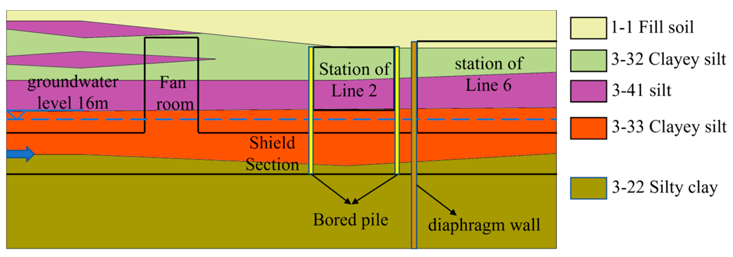
2.1. Project Information

The experiment of cutting retaining piles at existing stations was carried out in the Miaopu Station to Erligang Station section of the Zhengzhou Metro Line 6 Phase I project. The buried depth of the tunnel is 18.56 m. The total length of the left line is 61.625 m, and the total length of the right line is 59.529 m. Metro Line 6 passes underneath the existing Erligang Station of Metro Line 2, and the shield tunnels on the left and right lines need to cut through five station retaining piles. The retaining piles are drilled grouting piles with a concrete strength grade of C40. The diameter of the pile foundation is 1000 mm, and the spacing is 1400 mm. It is equipped with 11 main bars with a diameter of 25 mm and circular spiral hoops with a diameter of 10 mm and a spacing of 100 mm. The shield machine began to cross the existing station of Line 2 about 36 m after the beginning from the air shaft. Due to the existence of existing stations in the upper part, the traditional method is difficult to implement. Therefore, it is ensured that the shield machine is driven to the receiving end as quickly as possible through the adaptive transformation of the shield machine. As the first tunnel cutting through the pile foundation, the right line provides a reference for the rear left line tunnel. As the first tunnel cutting through the pile foundation, the right line provides a reference for the rear left line tunnel. The plane position relationship between the section line and the Erligang station of Line 2 is shown in Figure 1.
The shield machine first cuts the retaining piles on the west side of the station of Line 2, then cuts the retaining piles on the east side after passing through the station of Line 2. When the shield machine reaches the west end of the station on Line 6, it is received by using the steel sleeve. In the process of pile cutting, the pile foundation may damage the cutterhead. When the operation is improper, the cutter’s wear will be accelerated. During the whole process of shield excavation in the cohesive soil layer, it is necessary to ensure the flow plasticity of the muck and prevent the mud cake in the central area of the cutterhead and soil warehouse. The tunneling parameters should be strictly controlled within the allowable range to ensure the station’s safety.

2.2. Geological Situation

The maximum longitudinal gradient of the shield line between Miaopu station and Erligang station is 25%, and the minimum longitudinal gradient is 2%. The minimum buried depth of the tunnel is about 18.4 m, and the maximum buried depth is about 25.2 m. The groundwater depth is 16 m. The shield tunnel passes through the stratum, which is mainly composed of silty clay, which is medium- and low-compressive soil. It has a high bearing capacity and good engineering properties, which meet the load requirements of the upper structure. It can be used as the natural foundation-bearing layer of the interval tunnel. The geological profile of the longitudinal section of the line is shown in Figure 2. The mechanical properties of geological units are shown in Table 1.

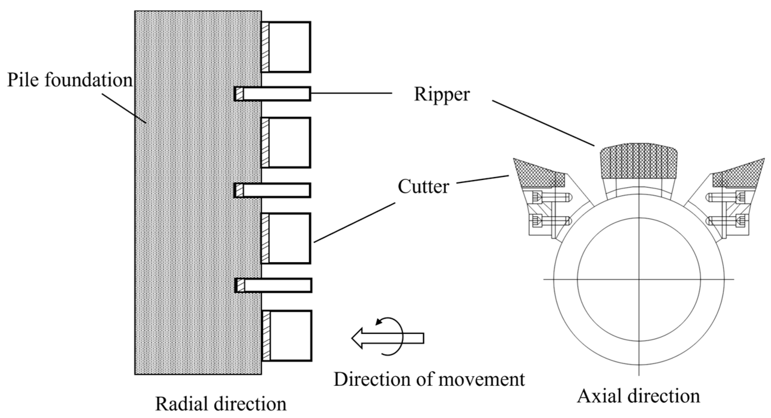
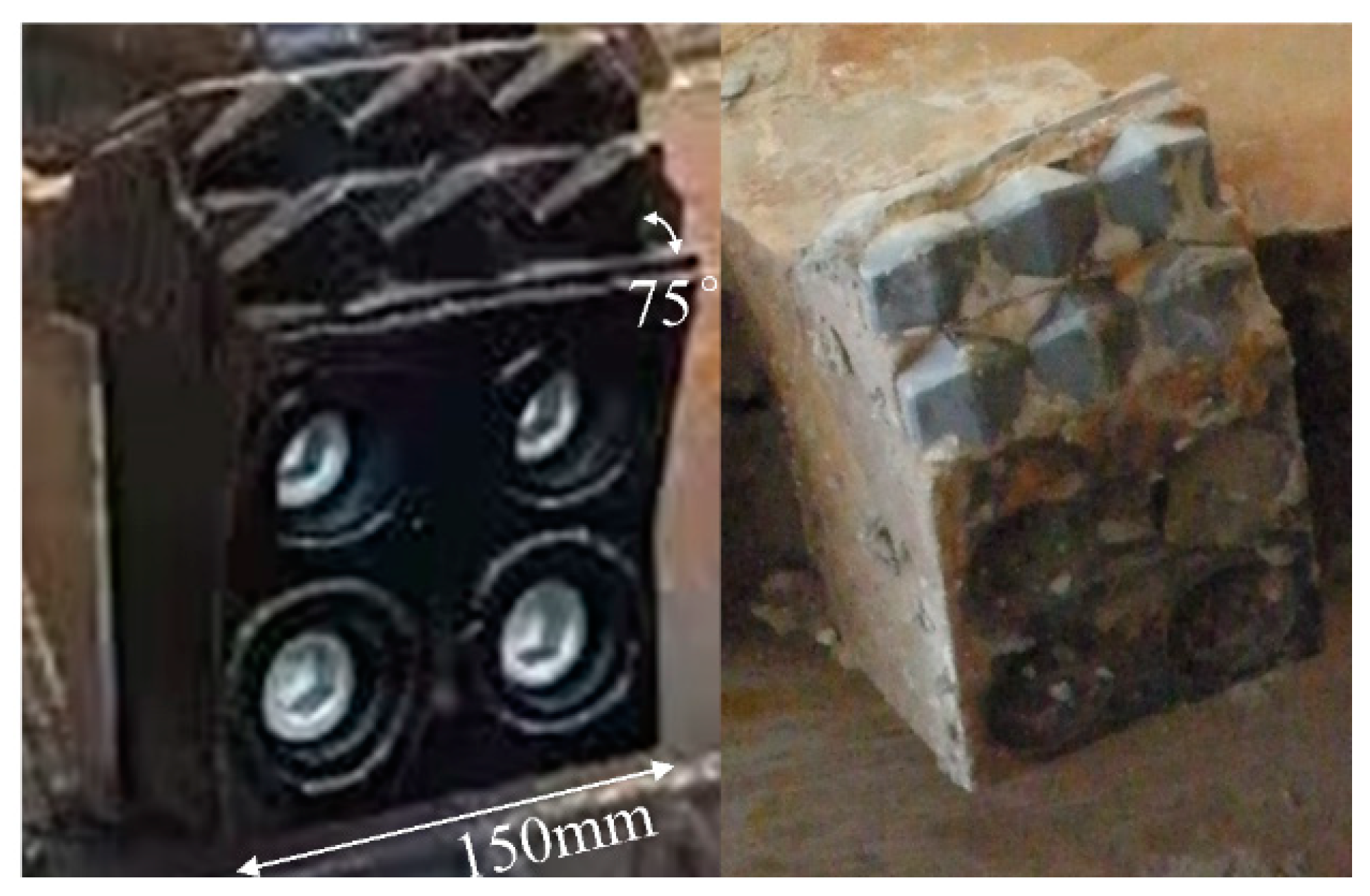
2.3. Arrangement of Shield Cutters

The design of the shield cutterhead adopts a combination of ripper and cutter to cut the soil and pile foundation, as shown in Figure 3. The ripper and cutter are arranged in the middle of the spoke of the cutter head according to the law of double Abbott spiral lines. The height of the ripper is larger than the height of the cutter, which can significantly improve the cutting fluidity and greatly reduce the torque of the cutter. Because the cutterhead often needs forward and reverse rotation, it is mainly arranged on both sides of the main beam and the auxiliary beam. The high-strength cemented carbide is embedded in the cutter head to strengthen the hardness and wear resistance. The combination of ripper and cutter is more suitable for cutting soil and pile foundation, and the cutters play a major role. Therefore, the cutter is selected to simulate the working conditions of cutting concrete pile foundations.

3. Numerical Model of Cutting Concrete

The drilled grout pile is composed of concrete and steel bars. Because the main object of cutting pile foundations is concrete and the cutting of steel bars is more complicated, only the failure mechanism and stress characteristics of cutting concrete are considered in this paper. The cutting mechanism of steel bars will be studied in the future. Tools cutting is a very complex nonlinear dynamic, and the numerical model is established through the finite element analysis software ANSYS-WORKBENCH 2020 by using the subroutine ANSYS-LS-DYNA-MANAGER calculation method and LS-PREPOST for post-processing operations.

3.1. Parameters of Concrete Constitutive Model

The commonly used constitutive models of concrete include the Forrestal model, the Holmquist-Johnson-Cook (HJC) model, (the Riedel-Hiermaier-Thoma) (RHT) model, and so on. The HJC model considers the effects of hydrostatic pressure on stress, strain rate effects, and material damage. It is suitable for describing the damage, fracture, and crushing of concrete under high-speed impact or penetration. Therefore, the HJC model is used as the constitutive model of concrete for cutting simulation. The HJC constitutive model mainly includes three parts: the yield surface strength model, the state equation, and the damage evolution equation. Each part is briefly introduced below [19,20].

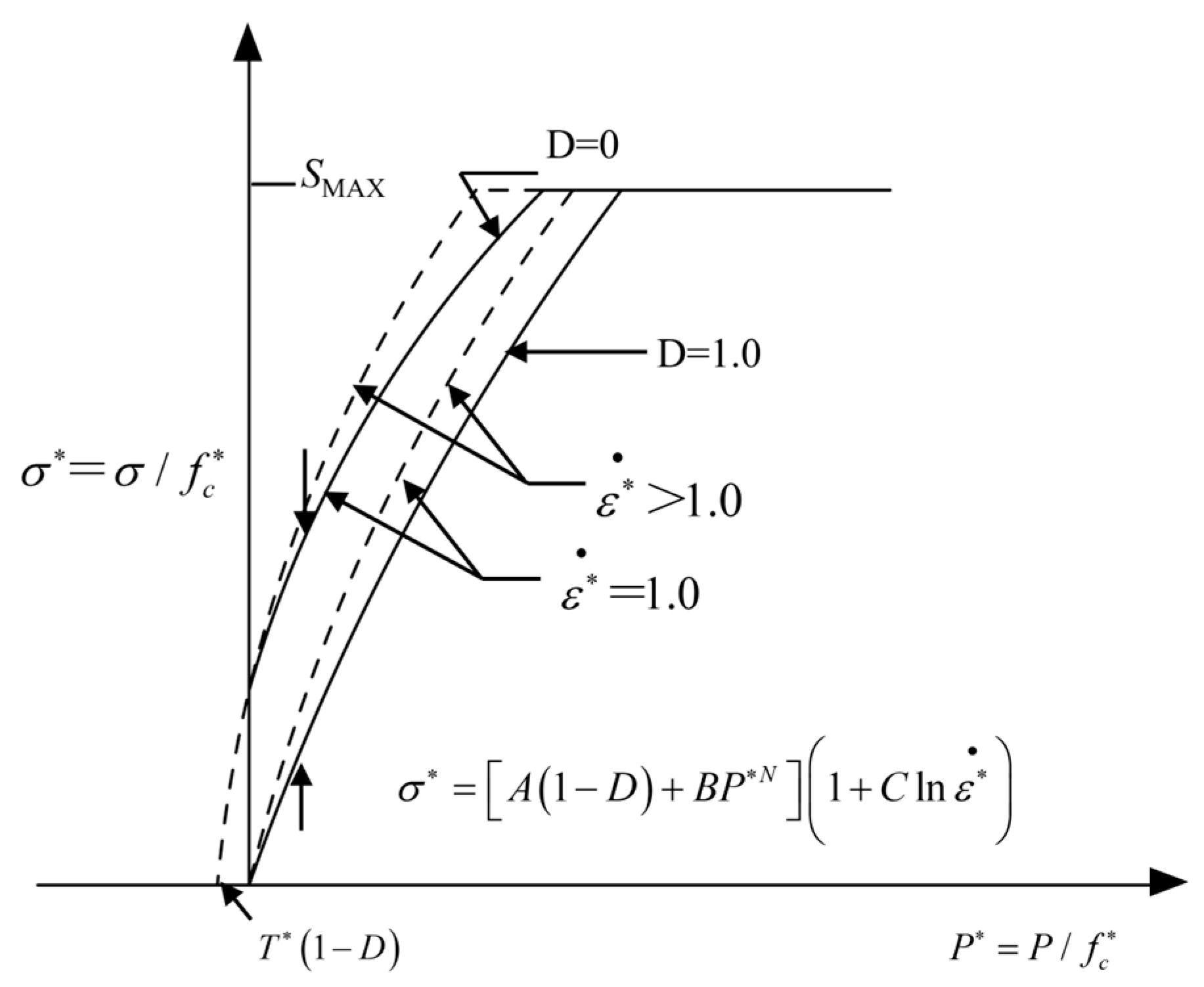
3.1.1. Yield Surface Strength Model

The yield surface strength equation of the HJC model is shown in Figure 4, and the function expression is:
σ * = A ( 1 D ) + B P * N ( 1 + C I n ε ˙ * )
where, σ * = σ / f c is the normalized equivalent stress; σ is the actual equivalent stress; fc is the quasi-static uniaxial compressive strength, S max is the maximum standardized strength of concrete material; A is the normalized cohesive strength coefficient; D is the damage coefficient (0 ≤ D ≤ 1); B is the normalized pressure hardening coefficient; P * = P / f c is the standardized hydrostatic pressure; P is the actual pressure; N is the pressure hardening coefficient; C is the strain rate coefficient; ε · * = ε · / ε 0 · is the dimensionless strain rate; ε · is the loading strain rate; ε 0 · is the reference strain rate.

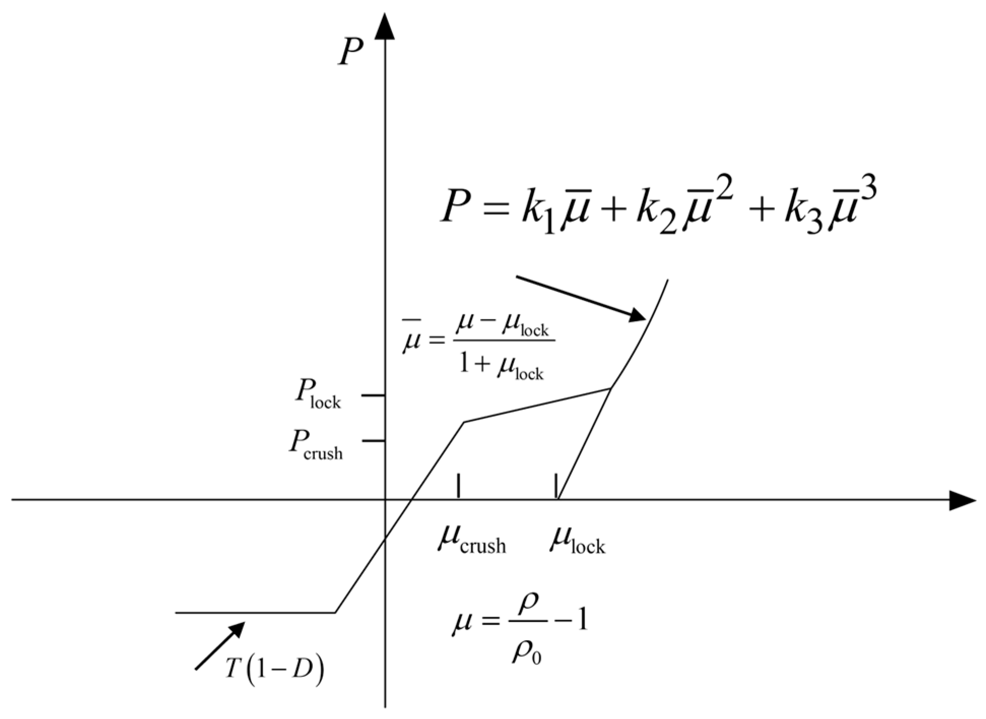
3.1.2. Equation of State

The HJC model state equation is used to describe the relationship between hydrostatic pressure and volumetric strain of concrete, which is divided into tensile and compressive state equations, as shown in Figure 5.
Compression state equation
① Linear elastic stage ( p < p c )
At this stage, the material strain is positively correlated with the pressure, and the expression is as follows:
p = K e μ
where, K e = P c / μ c is the bulk modulus; μ = ρ / ρ 0 1 is the unit volume strain; ρ and ρ 0 are the unit real-time density and initial density, respectively.
② Transition stage ( p c < p < p l )
At this stage, the concrete structure begins to produce plastic strain and cracks, and continues to expand, and the internal pores are gradually pressed out. The expression is as follows.
p = p c + ( p l p c ) ( μ l μ c ) / ( μ μ c )
where, p l is the critical pressure of compaction; μ l is the corresponding volume strain.
③ Compression stage ( p > p l )
At this stage, the concrete is completely compacted into a dense medium, and the relationship is as follows.
p = k 1 μ ¯ + k 2 μ ¯ 2 + k 3 μ ¯ 3
where, μ ¯ = ( μ μ l ) / ( 1 + μ l ) is the modified volume strain; k 1 , k 2 , k 3 is the parameter of the state equation.

3.1.3. Damage Model

The cumulative plastic strain constitutes concrete damage, including equivalent plastic strain and plastic volume strain. The damage evolution model is shown in Figure 6, and the expression is as follows.
D = Δ ε p + Δ μ p ε p f + μ p f
where, ε p f + μ p f = D 1 ( P * + T * ) D 2 ε f min is the plastic strain accumulation of concrete under normal pressure; D 1 and D 2 are the damage constant; When P * = T * , the concrete cannot bear any plastic strain, so the damage constant; ε f min is added to allow the minimum plastic strain for concrete crushing; T * = T / f c is the maximum tensile pressure that the material can withstand; T is the maximum tensile strength of the material.
The Lagrange single-point integral algorithm is used to simulate the concrete penetration problem. There are 21 different types of parameters in the HJC model, and the determination of parameters requires a variety of experiments and data fitting. In this paper, the basic parameters are obtained by calculation, and the remaining parameters are taken according to the reference [19] and adjusted reasonably. The specific parameters are shown in Table 2.
For the selection of the software parameter FS, when FS is positive, the material is in compression failure mode; when FS is equal to 0, the material is in tensile damage failure mode. When the FS is negative and the material cumulative damage D < 0, the material fails [21,22,23]. The JHC constitutive is more comprehensive for the description of compression damage. In this paper, FS is selected as the positive compression failure mode, and the possible tensile failure and shear failure of cutting concrete are also considered by setting the MAT_ADD_EROSION failure criterion of LS-DYNA. The software parameter FS is adjusted repeatedly according to the calculation results until it meets the actual working conditions to simulate the multi-aspect damage of concrete materials under the action of shield cutting penetration.

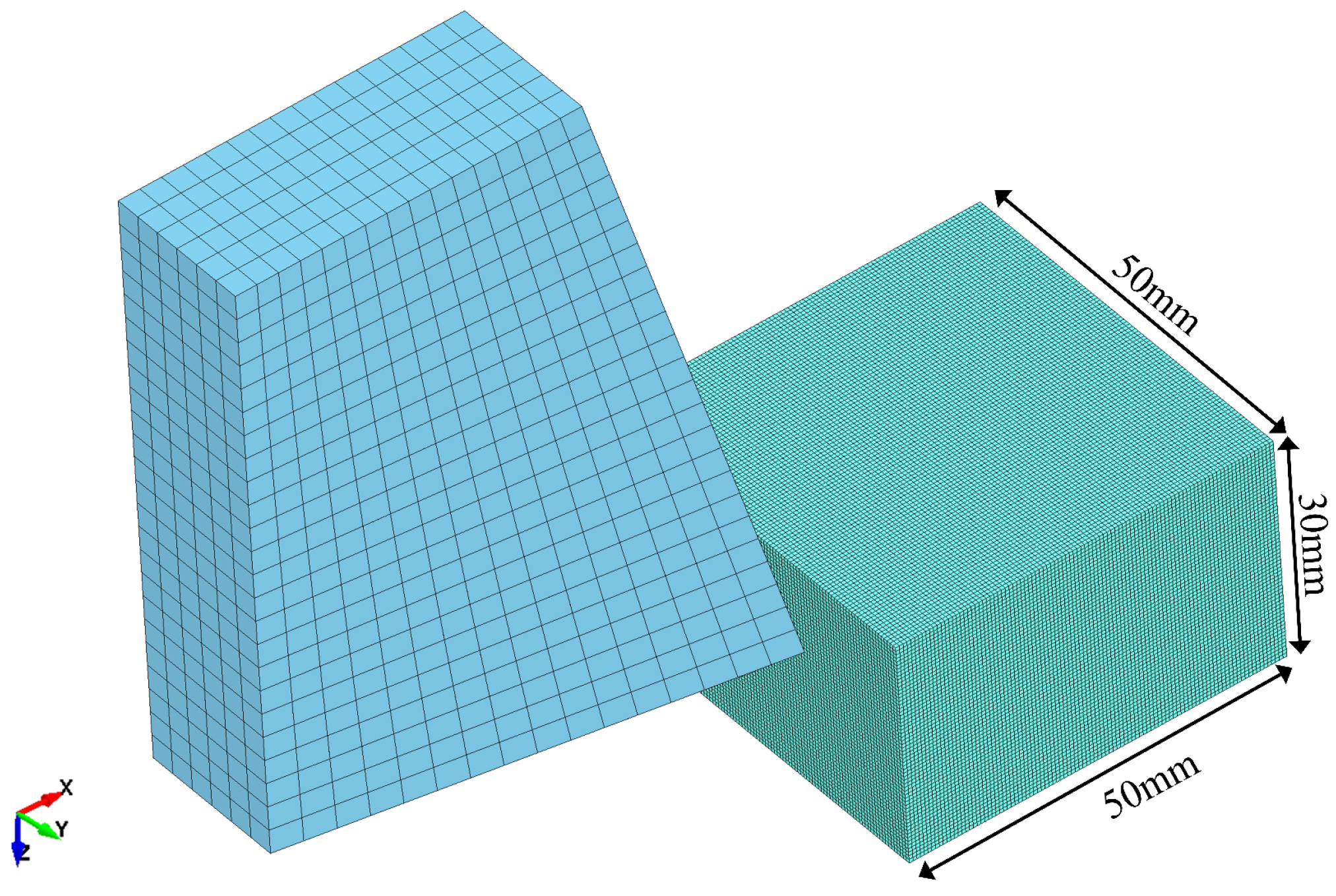
3.2. 3D Model of Cutter Cutting Concrete

The three-dimensional finite element model of a shield cutter cutting a concrete block is established by ANSYS-WORKBENCH with the size of a concrete block 50 × 50 × 30 mm. Considering the accuracy and efficiency of the model calculation, the Solid 164 element is selected to sweep the mesh, and the number of elements is determined to be 600,000. Due to the large rigidity of the shield tool, the stress in the cutting process is mainly concentrated at the contact point of the tool tip. Considering the calculation efficiency, the tool is set as a rigid body, and the mesh density is appropriately reduced. It is divided into 2305 elements. The model is shown in Figure 7.
The PRESCRIBED_MOTION_RIGID keyword is used to define the stable speed of the cutter tool’s cutting process. The linear velocity of the cutter tool motion calculated by Formulas (6) and (7) is from 0.17 m/s to 0.2 m/s, and 0.2 m/s is taken in this paper.
ω = 2 π n
v = ω r
where ω is the angular velocity of cutter tool motion, v is the linear velocity of cutter tool movement, n is the rotational speed of the cutter tool on the cutterhead, and r is the radius of the cutterhead.
The contact type selection is very important for cutting simulation. Usually, the contact algorithm methods include the dynamic constraint method and the penalty function method. The penetration problem is solved by introducing an interface contact force proportional to the major surface stiffness and penetration depth. The contact major surface is defined as the tool surface, and the contact minor surface is set as the contact surface between the concrete block and the cutter tool using the erosion surface contact algorithm card. The dynamic and static friction coefficients are defined as 0.25 and 0.18, respectively [24].
The shield cutter cutting pile foundation is simplified into two directions: penetration and cutting. In the simulation, the penetration depth is adjusted by changing the relative position of the initial tool and the concrete penetration direction (Z). Except for the cutting direction (X), the displacement and rotation of the cutter tool in other directions are constrained to ensure that the cutter tool can only move along the X direction to simulate the cutting of concrete. For concrete blocks, fixed constraints are used except for the cutting surface. Considering the actual situation, the non-reflection condition boundary is added to avoid the influence of stress wave reflection at the boundary. The output number of frames is set to 100.

4. Failure Mechanism and Mechanical Properties of Cutting Concrete

4.1. Failure Mechanism of Cutting Concrete

The force generated by the cutter cutting concrete can be divided into cutting force, tangential force, and penetration force according to the coordinate axes X, Y, and Z. The cutting depth of 10 mm and the width of 20 mm of the model tool cutting concrete are taken as examples. The equivalent stress cloud chart and damage chart shown in Figure 8 and Figure 9 can divide the cutting process into three stages.
(1) In the initial cutting stage, the cutter tool gradually approaches the concrete surface and produces extrusion on the contact face. As the cutter tool continues to cut deeper, it has a greater impact on the concrete and generates more energy in a short time. Under the action of the cutting tool’s movement direction, concrete is first subjected to an initial impact. The concrete at the front of the cutter head is subjected to a large extrusion stress, which is gradually compacted and transfers pressure to the surrounding area. When the compressive stress reaches the compressive strength of the concrete, it is crushed to produce a dense core, resulting in cracks that transmit to the surrounding concrete. Due to the large difference between the internal and external deformation, the surrounding area is finally damaged by tension, which manifests as a small-scale collapse of concrete near the cutter head.
(2) In the mid-cutting stage, as the alloy cutter head drives into the concrete at a constant speed, the cutter tool repeatedly squeezes the concrete and continuously cuts the concrete on the path. Since the constitutive model has a defined compression failure criterion, many concrete elements are directly deleted during the cutting process. When the concrete element is removed after reaching the failure criterion, there is still residual stress and strain in the area where the cutter passes. The cutter cannot produce a large force extrusion to break the concrete outside the contour of the cutter.
(3) In the final cutting stage, when the cutter tool is about to reach the end of the concrete, cracks will be formed at both ends of the concrete in advance, which are consistent with the cutting direction of the cutter tool. As the tool continues to move, the whole piece of concrete is peeled off to form a jumping crushing. After that, the cutter tool no longer contacts the concrete, the force drops to 0, and the whole cutting process ends.
Three maximum pressure and tension elements are taken for the model, as shown in Figure 10. The red lines refer to the maximum compression element, and the blue lines refer to the maximum tension element. The green line is the outline of the cutter, and the black line is the outline of the concrete. The maximum compressive stress of the concrete element is generated at the front cutter head. The maximum tensile stress is applied to the concrete element beyond a certain distance from the cutter head. From the tensile and compressive stress cloud chart, the nearest position to the cutter head is the maximum pressure interval, and the interval transmits the compressive stress wave to the surrounding concrete. It gradually decays to a negative value with the increase in distance, resulting in the tensile failure of the surrounding concrete. It shows that the cutter not only breaks the concrete in the contact area of the tool but also destroys the concrete in a certain area in front of the cutting direction. It is verified that the cutting mechanism is that the front concrete is crushed to produce a dense core, and the stress is transmitted to the surrounding concrete. Due to the difference in deformation, the tensile failure of the concrete element within a certain range of the periphery of the cutter head causes the jumping crushing.

4.2. Cutting Force Characteristics

The following conclusions can be drawn from the contact force curve in Figure 11.
(1)
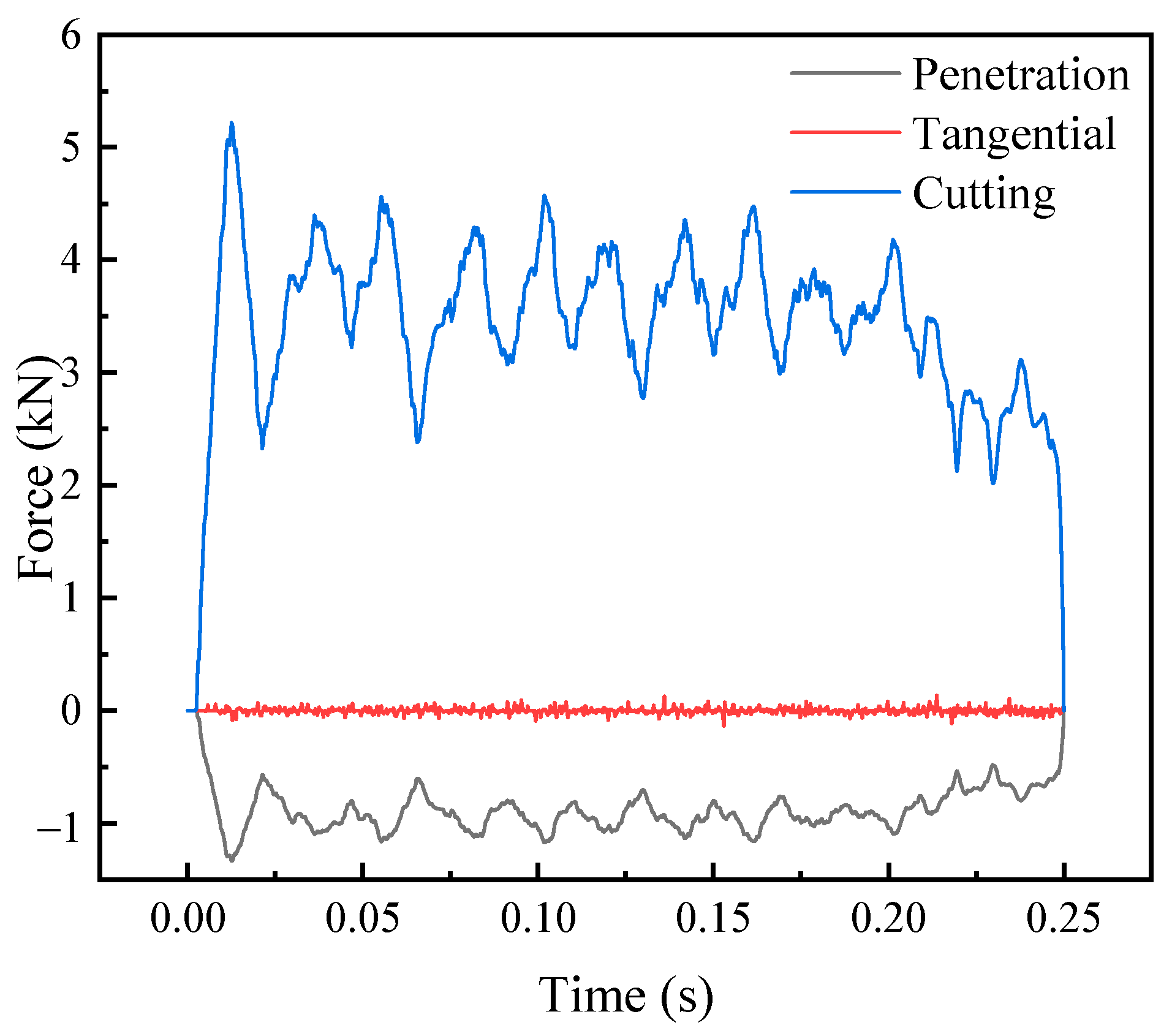
The whole cutting process always maintains cutting force > penetration force > tangential force. For the positive rake angle cutter tool, the cutting force is significantly greater than the penetration force, with a good correlation.
(2)
Because the cutter is regular and symmetrical in the direction of cutter width, the tangential force changes slightly near zero. Under the current cutting conditions, due to the symmetry of the tool structure on both sides, the lateral forces generated on both sides offset each other.
(3)
In the initial stage of the process of a cutter contacting concrete, the contact force increases rapidly with the increase in the contact area of the cutter. After reaching the maximum value, it begins to enter the steady-cutting state. Due to the uncertainty of the contact position and the deletion element, the force is discontinuous, and the cutting force fluctuates around the average value. Therefore, the shield cutter is easily damaged by large impacts during the initial cutting process.

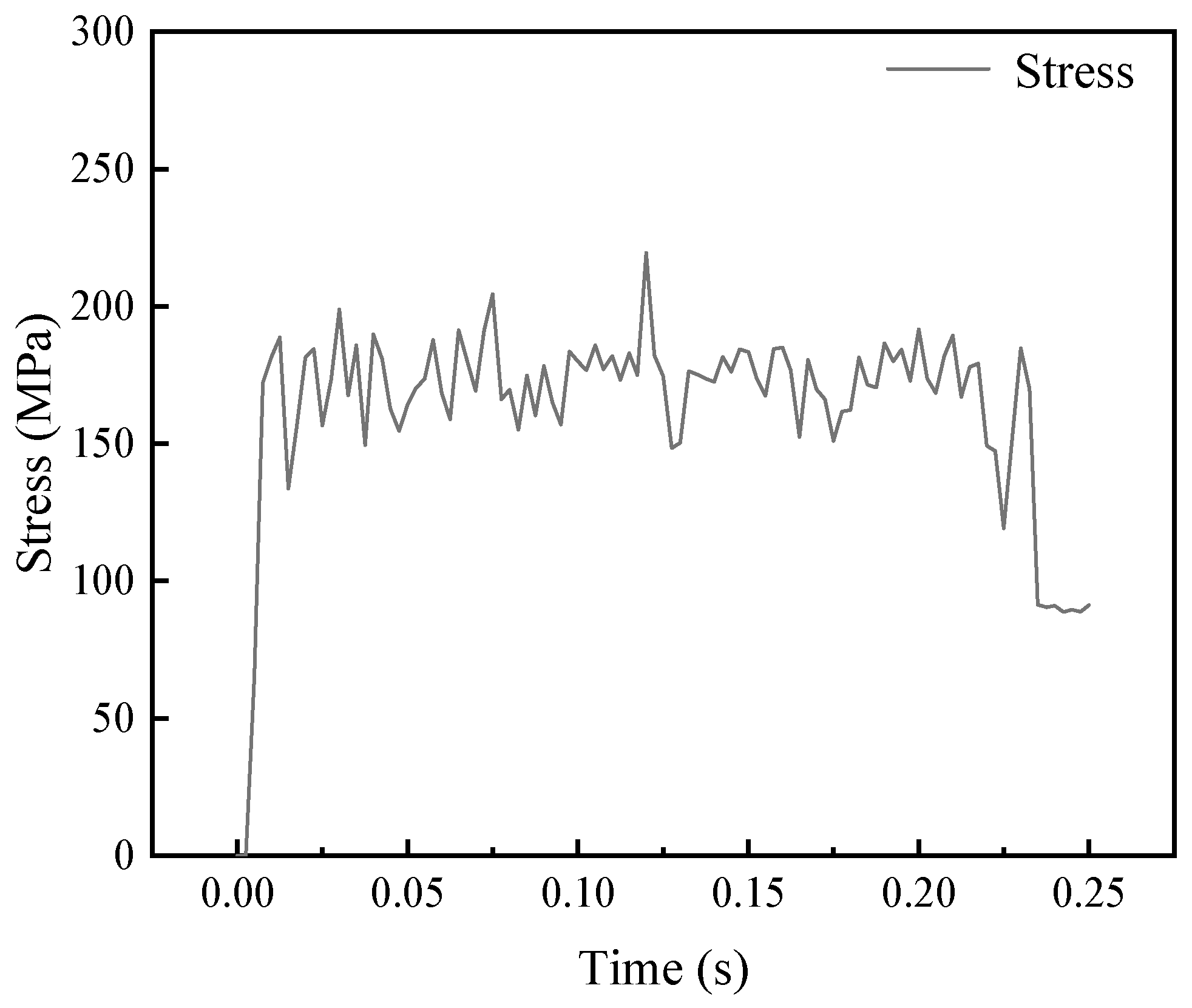
4.3. Cutting Stress Characteristics

By analyzing the stress change curve in Figure 12, the following conclusions can be drawn.
(1)
During the cutting process, the equivalent stress of concrete is maintained at 160 MPa, and the maximum value is 219 MPa, which is much larger than the compressive strength of concrete.
(2)
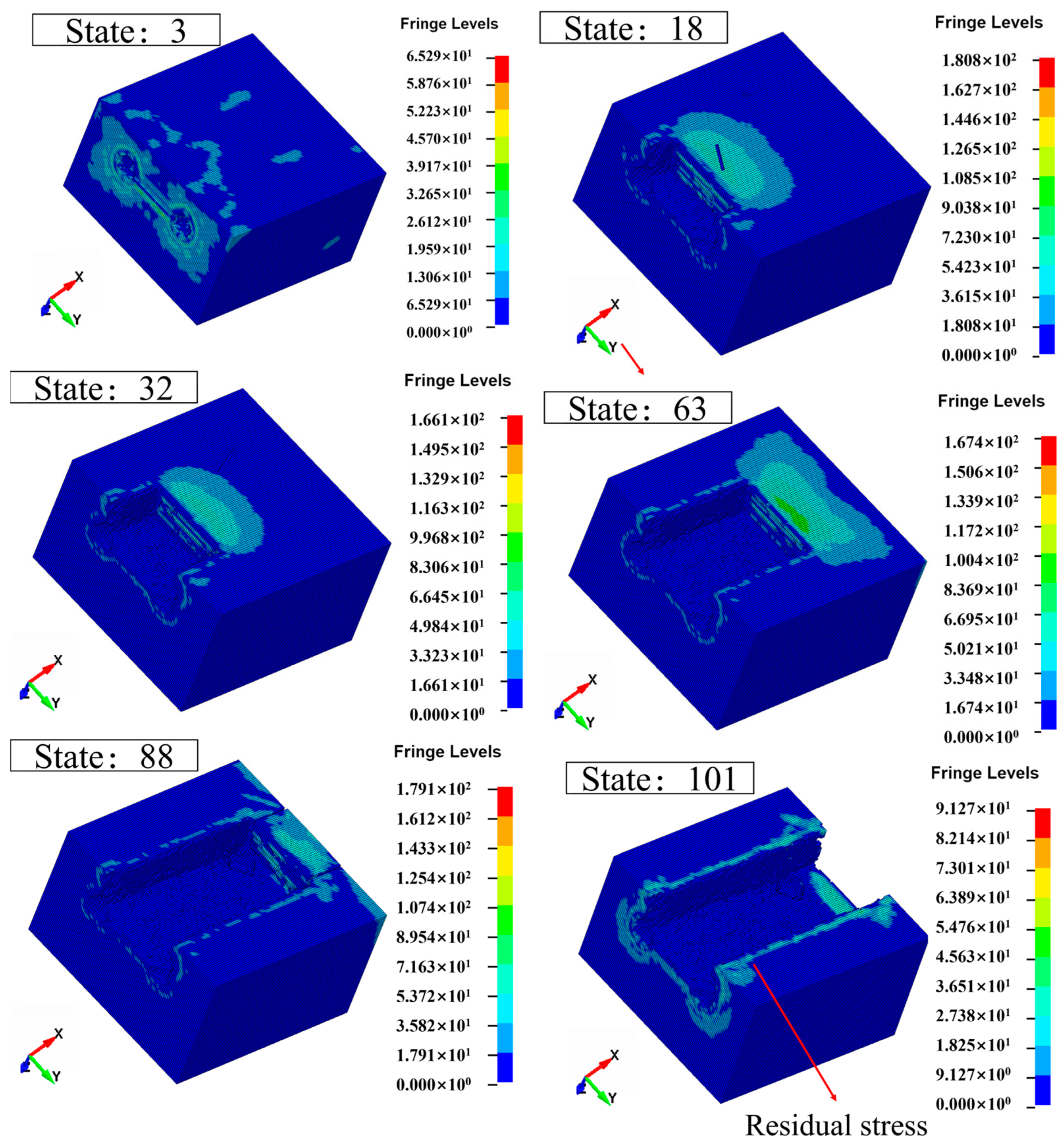
During the cutting process, the maximum stress occurs at the contact area between the tool and concrete and gradually decreases outward. As the saw blade cuts deeper into the concrete, the maximum stress area of the concrete shifts along the cutting direction of the blade.
(3)
Residual stress and strain still exist in the cutting tool passing area. It is because plastic deformation occurs in concrete during cutting. The plastic deformation of the tool after unloading partially limits the recovery of deformation in the adjacent area, resulting in residual stress.

4.4. Analysis of the Influence of Different Factors on Cutting

Cutting parameters and tool parameters have a direct impact on the three-way cutting force. In this paper, the changes in cutting force under different parameters are analyzed from these two aspects. Cutting parameters include cutting speed and cutting depth. Tool parameters include cutter width, tool rake angle, tool shape, and tool spacing. It can be seen from the above that the lateral concrete will not be damaged by the cutting action of the tool, and the sandwich concrete ridge will be affected when the spacing between adjacent cutters is small enough. It is difficult to meet this condition in the actual tool arrangement, so the influence of the cutter spacing is ignored. A total of four working conditions were designed, as shown in Table 3. The effects of different cutting speeds, cutting depths, cutter widths, and tool rake angles on the three-way force were studied by taking the quantitative as the control group and the single variable as the experimental group. Cutting force and penetration force are defined as Ft and Fn, respectively.

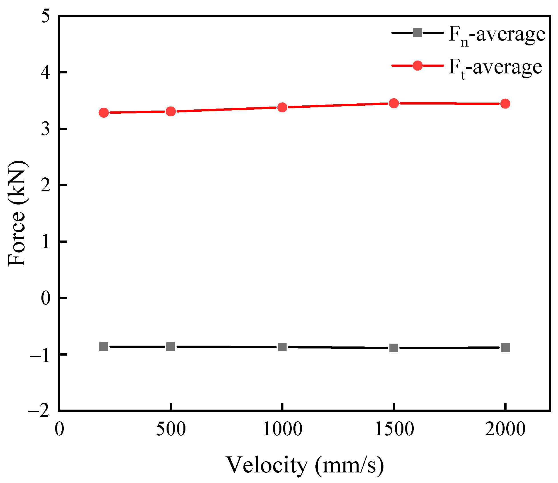
4.4.1. Cutting Speed

The cutter head movement of the shield machine is low-speed. The cutter is installed on the cutter head and rotates together to complete the cutting work. At present, most of the research on cutting focuses on high-speed cutting. It is believed that the influence of the cutting process manifests itself in the processes of strain strengthening and high-temperature softening. For high-speed cutting, thermal softening plays a dominant role. The heat generated by cutting changes the internal friction angle of the cutting material, thus changing the strain rate of the material and changing the cutting force.
For lower-speed cutting, the heat generated by cutting is very small, and the thermal softening effect is relatively weak. It has little effect on the strain rate of the material. And the model does not consider the temperature change, so the cutting force does not change much during lower-speed cutting. From the fitting curves of penetration force and cutting force at different cutting speeds in Figure 13, it can be concluded that under the current working conditions, the change of cutting speed between 200 mm/s and 2000 mm/s has little effect on cutting force and penetration force.

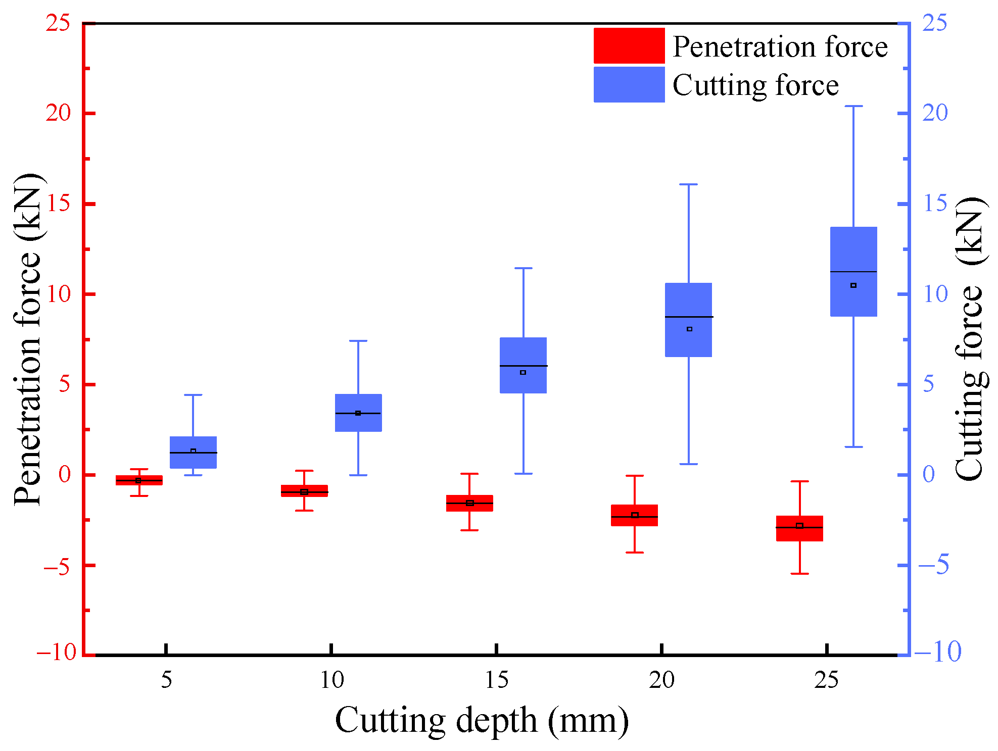
4.4.2. Cutting Depth
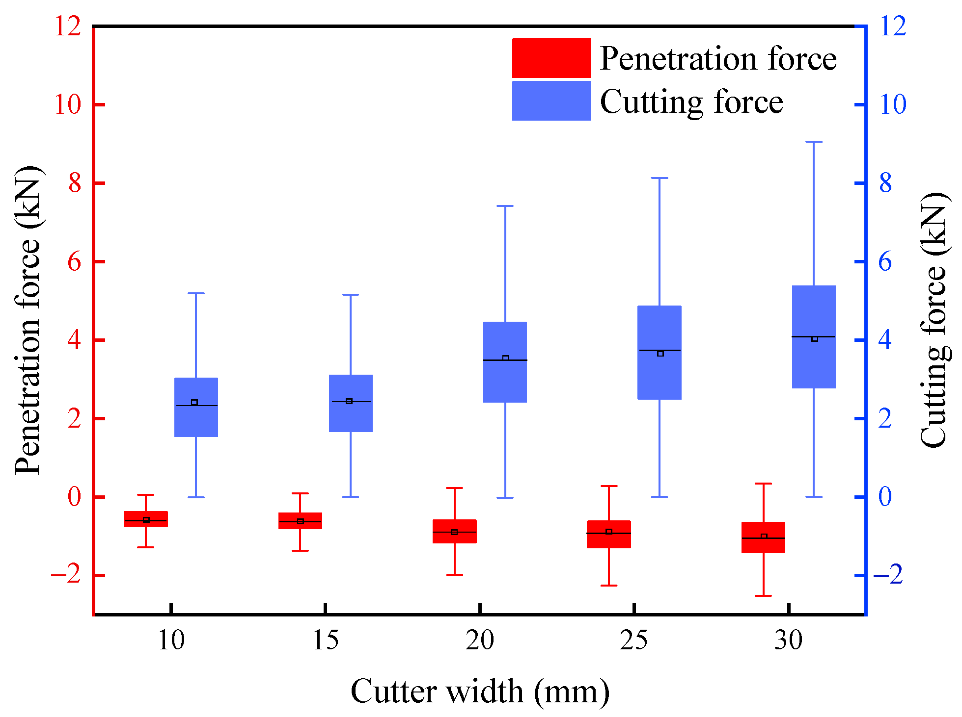
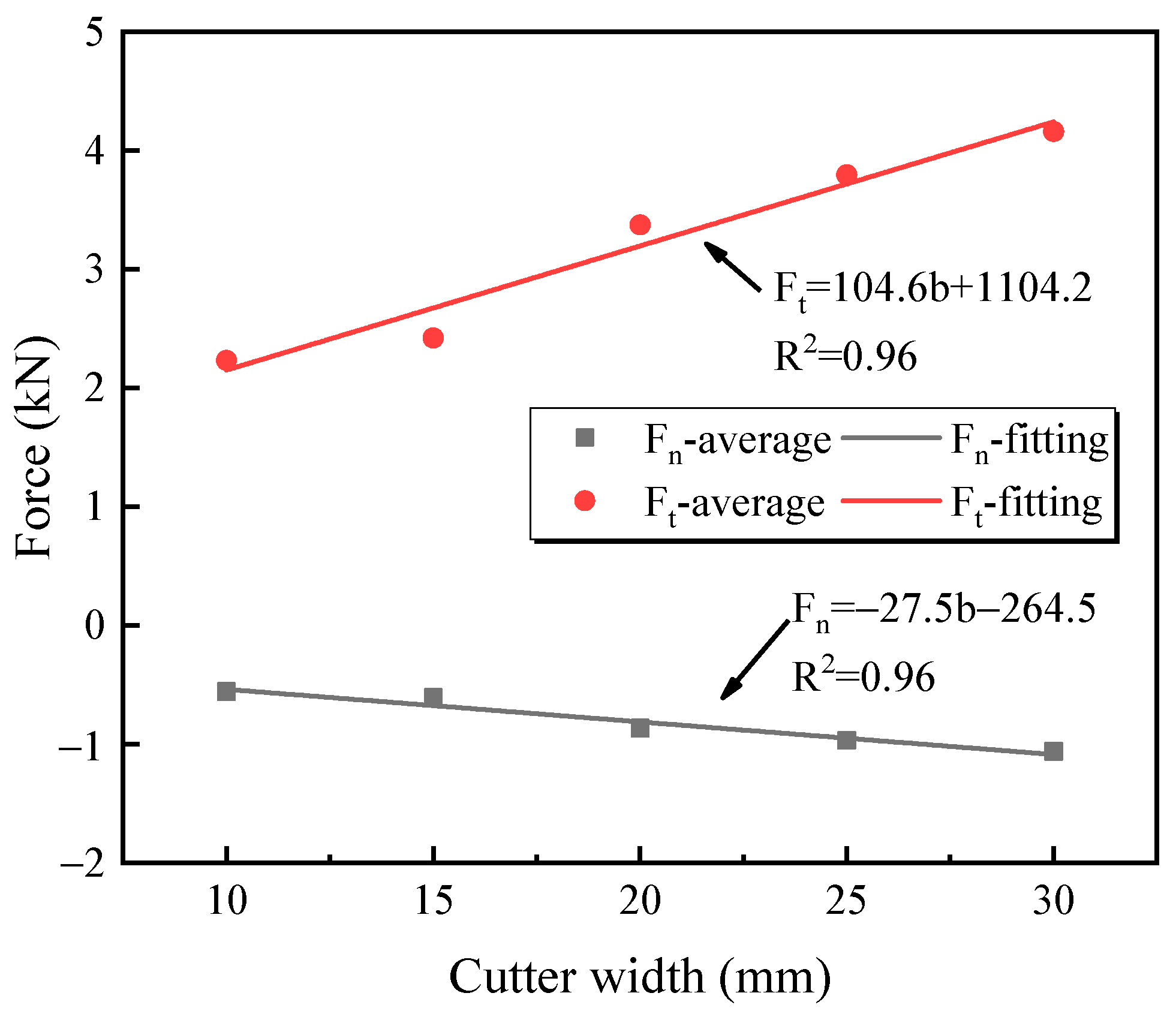
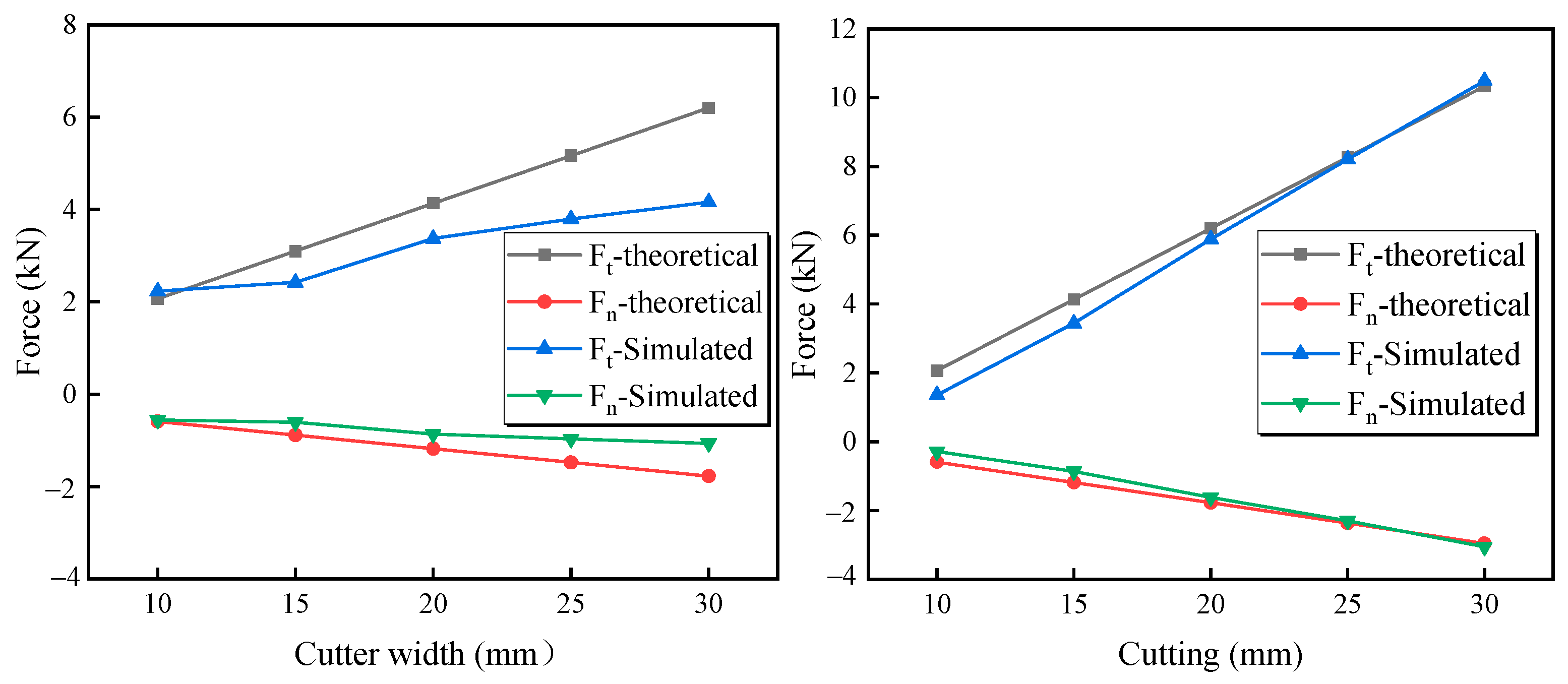
The influence of cutting depth on the penetration force and cutting force of cutting concrete is explored, as shown in Figure 14. The cutting depth has no effect on the overall trend of cutting concrete. The curve follows well the linear relationship between cutting force, penetration force, and cutting depth.
The double Y-axis box diagram of the data is shown in Figure 15. The length of the two lines represents the fluctuation range, and the middle line and the origin of the box are the median and the average, respectively. The cutting force and penetration force are highly linear with the cutting depth, and the fluctuation range of the two increases with the increase in cutting depth. The main reason is that the deeper the cutting, the greater the contact area between the tool and the concrete. It leads to an increase in the randomness of the internal damage to the concrete, and the size of the debris increases accordingly. At the same time, the effective area of the tool contact is multiplied, and the fluctuation range of the reaction in the cutting force and penetration force is increased. Therefore, during the construction process, the height difference of the tool should be reasonably controlled to avoid excessive force on the single tool, which not only causes a significant increase in tool wear but also may cause the cutterhead to stop.

4.4.3. Cutter Width

The mean values of penetration force and cutting force calculated by different cutter widths are shown in Figure 16. With the increase in cutter width, the cutting force and penetration force increase not only numerically but also gradually. The reason is that the increase in cutter width increases the randomness of internal damage to concrete, and the size of debris.
The linear fitting of different cutter widths is shown in Figure 17, in which the slope of the cutting force is greater than the penetration force, indicating that the cutter width factor has a higher rate of change in the cutting force than the penetration force. Unreasonable cutter width will lead to unbalanced force and increase the power consumption of the shield cutter head.

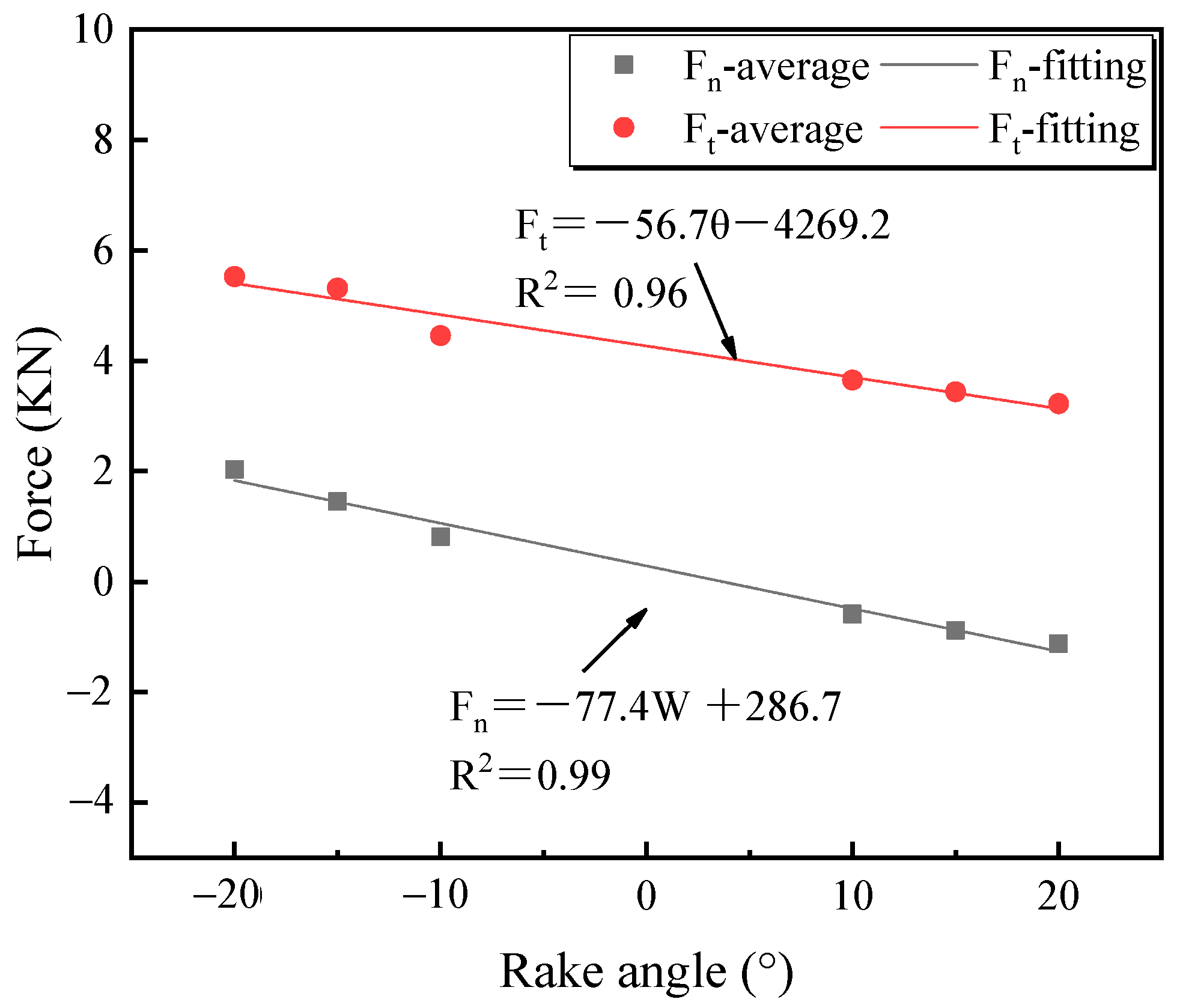
4.4.4. Angle of Cutting Edge

The mean fitting of penetration force and cutting force for different tool rake angles is shown in Figure 18. The cutting force and penetration force decrease with the increase in tool rake angle. As the negative front angle is converted to the positive front angle, the penetration force changes from positive to negative. The reason for the analysis is that the rake angle is negative, and the cutting effect continues to weaken during the increase of the rake angle of the tool, so the cutting force decreases. When the rake angle changes from negative to positive, the direction of the penetration force changes. The overall performance of the tool penetration direction is oblique downward extrusion to oblique upward cutting, so the penetration force changes from positive to negative accordingly. Because the penetration force maintains a linear relationship with the cutting force, it is also decreasing.

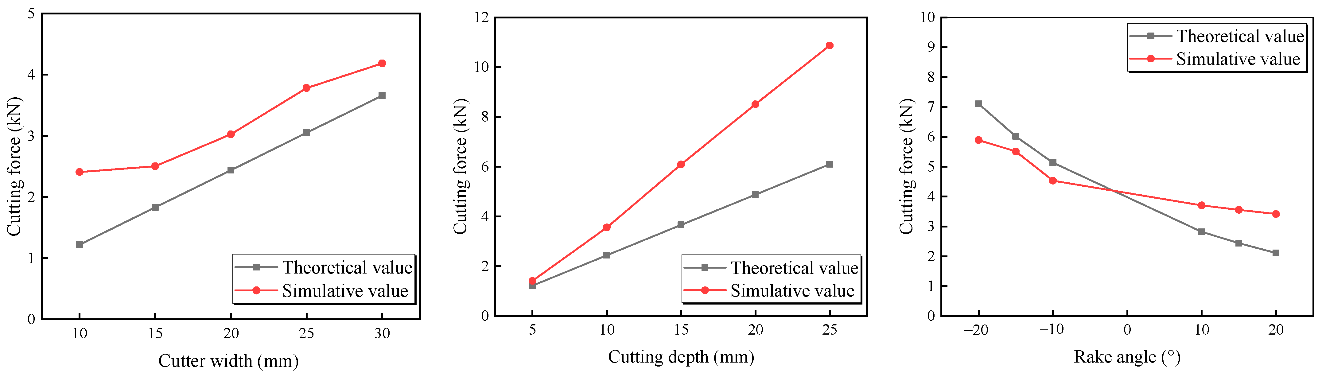
4.5. Model Verification

To verify the correctness of the cutting concrete model, a few scholars have completed the verification by formulating experiments [25], but there are few theoretical verifications for cutting concrete materials. Domestic and foreign scholars have carried out theoretical analyses on cutter cutting and obtained some cutter force model formulas. In this paper, two commonly used theoretical formulas are selected to study and verify the calculated and simulated values [26].

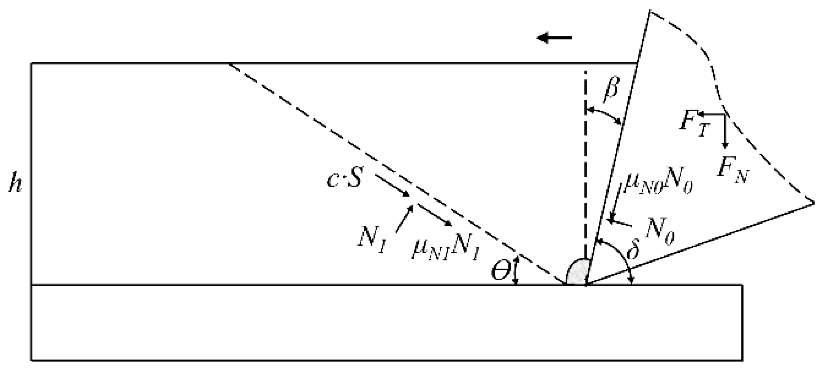
4.5.1. The I.Evans Model

To simplify the force model of the cutter, only the reaction force in the cutting direction of the cutter is considered, and the influence of the thrust generated by the cutting of the cutter is not considered. The force formula of the cutter is shown in Formula (8) [27].
F c = 2 σ T d w sin 1 2 ( π 2 α ) 1 sin 1 2 ( π 2 α )
Among them, F′c is the peak cutting force of the cutter, and the unit is N; σ T is the tensile strength of the cutting material, which is 3.92 MPa in this paper; d is the cutting depth, w is the cutter width, and α is the rake angle.
For the above simulation of different cutter widths, different cutting depths, and different rake angles, the corresponding theoretical values are calculated by the above formula, and the simulation values are plotted as shown in Figure 19. The remaining conditions remain unchanged: the cutting force increases with the increase in cutter width and cutting depth and decreases with the increase in rake angle. The theoretical and simulation changes are basically the same, which can verify the correctness of the simulation. It is worth noting that in the theoretical formula, the cutter width and the cutting depth are two independent parameters, and the product of the two is equal to the theoretical formula. The main sources of error are the following: (1) The model is affected by the mesh size, and the simulated value itself has a certain error. (2) Referring to the I. Evans’s theoretical calculation model, the friction angle between the cutter and the concrete is not considered when calculating the cutting force of the cutter, but the friction angle is considered in the model simulation, which is also the main source of error. The results are consistent, but in the simulation, the influence of the cutting depth and the cutter width on the cutting force is different, and the cutting depth affects the cutting force level more than the cutter width.

4.5.2. Theoretical Model of Japanese Scholars

The fractured part of the material is analyzed in isolation. The forces acting on the material on the fracture surface include normal forces, friction forces caused by fracture, and material adhesion forces. The tool acting on the rake face produces normal force and friction force on the material. As shown in Figure 20, the cutting force diagram of the cutter is shown. Combined with the force balance theory, two equations of tangential and normal directions can be obtained, such as Formulas (9) and (10):
X i = 0 , N 1 sin θ + μ N 1 N 1 cos θ + c S cos θ μ N 0 N 0 cos δ N 0 sin δ = 0
Y i = 0 , N 1 cos θ μ N 1 N 1 sin θ c S sin θ μ N 0 N 0 sin δ + N 0 cos δ = 0
The normal force N1 acting on the material on the fracture surface and the normal force N0 acting on the material by the tool on the rake face can be obtained by solving the above two equations. The sum of the forces in the same direction is the tangential force and normal force generated by the tool cutting, which are respectively Formulas (11) and (12):
F T = μ N 0 N 0 sin δ N 0 cos δ = c S A ( sin θ + μ N 1 cos θ )
F N = μ N 0 N 0 cos δ N 0 sin δ = c S ( cos δ + μ N 0 sin δ ) B
In the formula: A = cos δ μ N 0 sin δ sin δ + μ N 0 cos δ + cos θ μ N 1 sin θ sin θ + μ N 1 cos θ ; B = ( cos δ μ N 0 sin δ ) ( sin θ + μ N 1 cos θ ) + ( cos θ μ N 1 sin θ ) ( sin δ + μ N 0 cos δ ) ;  FT and FN are the tangential force and normal force of the cutter; μ N 0 and μ N 1 are the friction coefficients of the contact surface between the cutting material and the blade and the shear fracture surface, respectively. c is the material cohesion; δ is the cutting angle, which refers to the angle between the tool rake face and the cutting plane; S is the area of the fracture surface; φ is the internal friction angle of the material.
Figure 21 shows the theoretical calculation results and simulation results for cutting force and normal force. It can be seen from Figure 21 that the cutting force increases with the increase in cutter width and cutting depth. The theoretical and simulation changes are basically the same, and the correctness of the simulation is verified. The slope of different depth changes is greater than that of different cutter widths.
As for the formula for calculating cutting force, cutter width and cutting depth have always been considered single factors. In practical projects, cutter width, cutting depth, and rake angle jointly affect the cutting area and cutting force. Next, the significance of cutter width, cutting depth, and rake angle on cutting force is comprehensively studied.

5. Significance Analysis of Cutting Influencing Factors

Through the simulation of cutting concrete under different conditions, the influence of different cutting parameters and tool parameters on the cutting effect and cutting force is obtained. In shield construction, each influencing factor interacts with each other and jointly affects the final pile cutting results. Therefore, this section uses statistical analysis software, Statistical Product and Service Solutions 23 (SPSS 23), to conduct an orthogonal test on the main influencing parameters. Range analysis and variance analysis were used to comprehensively judge the significance level of each factor [28].

5.1. Orthogonal Test Range Analysis

Select the factors that have a greater impact on the target as the research object. The orthogonal test is carried out for the three main parameters of the rake angle, cutter width, and cutting depth. Each parameter is set at three levels to analyze the significance level of each factor. For the above three-factor test, the simulation is carried out according to the orthogonal scheme. The cutting force was statistically analyzed to obtain the L9(34) orthogonal simulation, and the range analysis results are shown in Table 4.
Using range analysis, range R shows the degree of influence of different factors on the test target within its value range. According to the size of range R, the primary and secondary factors are arranged. The range analysis table and the comparison of R values can be preliminarily judged. Under the influence of cutting depth, the range R is the largest, and the influence on the target is the most obvious. Under the cutting speed factor, the range R is the smallest, and the influence on the target is the least obvious. Therefore, the influence of the three factors on the cutting force is ranked as follows: cutting depth > cutter width > rake angle, which is also consistent with the research results of Yang et al. [28].

5.2. Orthogonal Test Variance Analysis

The influence of the multiple independent variables on dependent variables was explored through a multi-factor analysis of variance. The sum of the squared deviation, degree of freedom, and mean square sum of each factor and error were calculated. The Statistical verification value (F) and Statistical significance value (sig) of each factor were obtained as shown in Table 5. The significance level of each factor for cutting force was judged.
The significance level in this paper is A = 0.05. The F0.05 in the F distribution table was compared with the calculated F value, sig value, and significance level A to determine the significance level of each factor.
According to n = 8 , m = 2 , The F0.05 can be obtained from Formula (13).
F 0.05 ( m , n m 1 ) = F 0.05 ( 2 , 5 ) = 5.786
Through Table 5, the F value and sig value of the rake angle, cutter width, and depth were compared with the theoretical values. The F value of the depth is the largest and the sig value is the smallest, and F = 116.827 > 5.786, sig < 0.05. It indicated that depth has the most significant effect on the cutting force. The second is the cutter width at which the F value is larger, and F = 19.266 > 5.786, sig < 0.05, It indicated that the cutter width has a significant effect on the cutting force. The F = 0.838 < 5.786 and sig > 0.05 of the front corner show that the main effect of the front corner is not significant.
Therefore, in practical projects, to improve the cutting efficiency, the cutting depth can be prioritized within a reasonable range, followed by increasing the cutter width, and finally considering the tool rake angle. The rake angle of the tool has less influence on the cutting force than the cutting depth and cutter width. Within a reasonable range, the smaller the cutting force, the smaller the tool wear.

5.3. Shield Machine Construction and Tool Parameter Optimization

(1)
The shield machine is equipped with a low-speed propulsion function to provide low-speed, stable thrust. The cutting depth as a construction parameter requires the shield machine to adjust the cutting speed and cutter speed control during the operation. The actual propulsion process speed was increased from 3 mm/min to 5 mm/min.
(2)
As a measure before pile cutting, the increase in cutter width will increase the force area of the cutter and further increase the cutting force. At the same time, it can reduce the number of cutter installations and reduce the design cost. The actual cutter width is increased from 100 mm to 150 mm.
(3)
When cutting the pile foundation, properly increasing the rake angle from 10° to 15° and slightly reducing the cutting force can ensure a reduction in tool wear. This is more suitable for long-term tunneling.
(4)
The innovative design of the cutter head has six teeth, and the upper and lower rows are arranged with three teeth each, which can further reduce tool wear and improve the fluidity of soil.
The cutter style of shield machine is shown in Figure 22. After the modification, the cutter of the shield machine successfully completed the cutting of the pile foundation, and the tool wear was small. It ensures that the shield machine passes through the pile foundation of the station safely and quickly.

6. Recommendations and Limitations

The following suggestions can be referred to in similar projects for shield-cut pile foundations:
(1)
In the initial stage of concrete cutting, the tool is easily damaged by large impacts, and this process should be carried out at low speed to provide stable thrust and avoid excessive wear of the cutterhead.
(2)
In the construction process, the height difference of the tool should be reasonably controlled to avoid the excessive force of the single tool, which leads to the shutdown of the cutterhead.
(3)
Before cutting the pile foundation, the cutter width should be adjusted appropriately according to the actual situation of the site to reduce the loss of the shield cutterhead. Appropriately increase the rake angle to reduce the wear of the cutterhead.
This paper studies the variation law of cutting force under different factors and the significance of influencing factors, which is mainly applicable to concrete materials. For pile foundations made of other materials, the conclusions of this study may not be applicable. The effect of different cutting depths, cutter widths, and rake angles on cutting force is not considered in the model. At the same time, the reinforcement effect of steel bars on concrete was not considered, which will be further supplemented and improved in subsequent studies.

7. Conclusions

Based on the direct cutting pile foundation project of Zhengzhou Metro Line 6 undercrossing the existing station, the failure mechanism and mechanical characteristics of the shield cutting pile foundation are studied by numerical simulation and theoretical analysis methods. The influence of different cutting parameters and cutter tool parameters on cutting force is discussed. The significance analysis of different factors is carried out, and the following main conclusions are drawn:
(1)
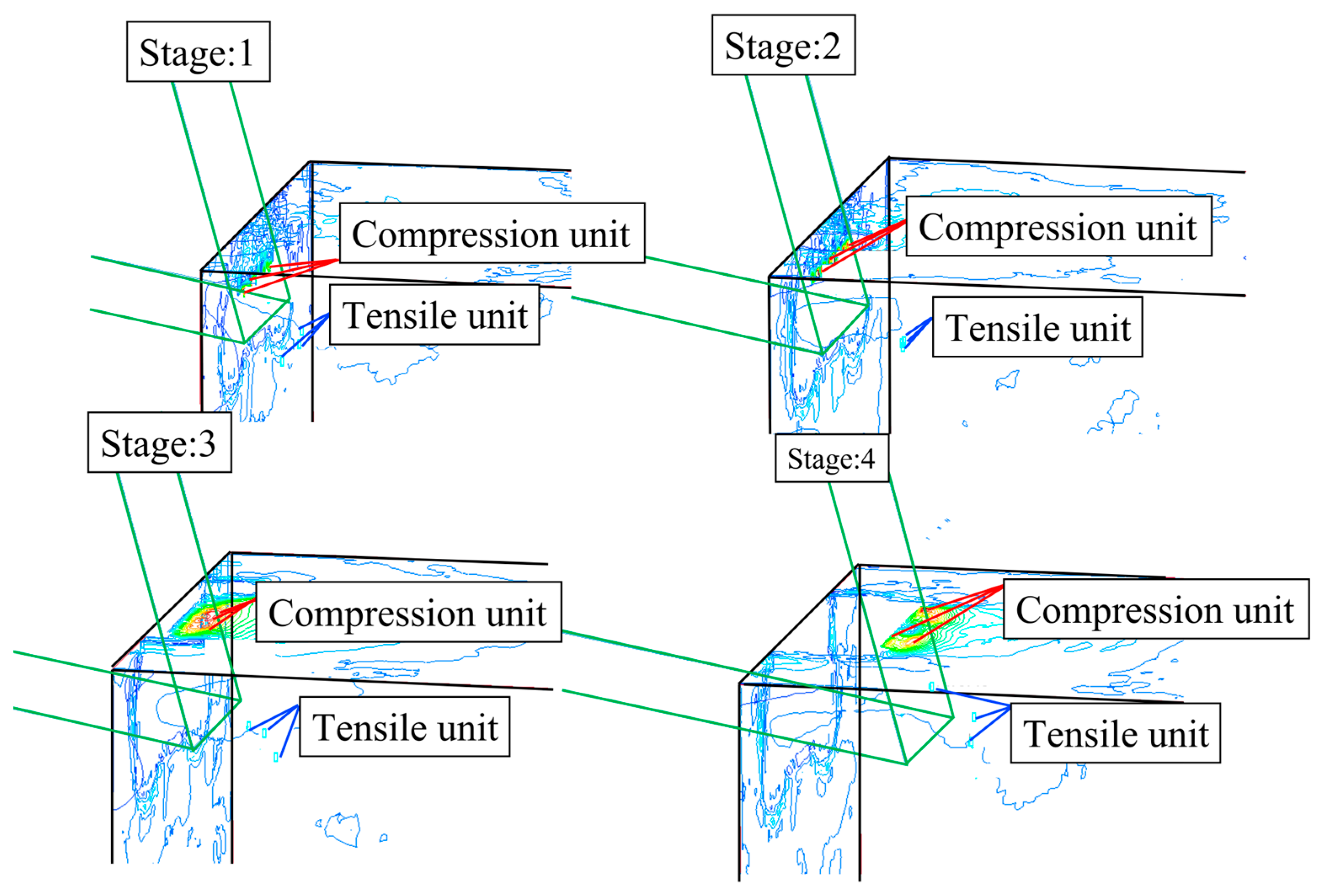
Cutting concrete can be divided into three stages: the initial cutting stage, the mid-cutting stage, and the final cutting stage. In the initial cutting stage, the concrete exceeds its compressive strength and is crushed under the extrusion of the cutter head. In the mid-cutting stage, the cutter tool continuously squeezes the concrete and continuously cuts the concrete on the path. In the final cutting stage, the whole stripped concrete forms a leap forward in crushing. The tool force drops sharply to 0, and the cutting process is completed. The cutting mechanism of the cutter tool is that the front-end concrete is crushed under pressure to produce a dense core. The stress is transmitted to the surrounding concrete, resulting in the tensile failure of the surrounding concrete unit and the leap-forward crushing.
(2)
The cutting force increases rapidly in a short time during the cutting process and begins to enter the steady cutting state after reaching its maximum value. When the cutting is complete, the cutting force drops sharply to 0. The whole cutting process always maintains cutting force > penetration force > tangential force, and the tangential force is basically 0.
(3)
Regardless of the cutting temperature, the contact force of the cutter is less affected by the cutting speed. The cutter contact force is linearly proportional to the cutting depth and cutter width, and the fluctuation range also increases. The cutter contact force is linearly and inversely proportional to the rake angle.
(4)
Through range analysis and variance analysis, the significance order of the three main influencing factors was obtained: cutting depth > cutter width > rake angle. It is suggested that the cutting depth be adjusted preferentially within the scope of reasonable construction, followed by the cutter width, and finally the rake angle.
In this paper, by simulating the working condition of a shield cutter in concrete cutting, the influence and significance of different factors on cutting law, cutting force, and cutting fluctuation were analyzed. It provides the basis for cutting parameter adjustment and tool transformation for practical engineering, reduces damage to the shield cutter head, and improves construction efficiency.

Author Contributions

Conceptualization, X.G., Z.L. and Y.L.; methodology, Z.L., H.D. and S.R.; software, K.Y.; validation, X.L., Y.L. and X.G.; formal analysis, J.M. and R.L.; investigation, S.R.; resources, X.G.; data curation, H.X. and R.L.; writing—original draft preparation, X.G. and Z.L.; writing—review and editing, Z.L., X.L. and X.G.; visualization, H.X.; supervision, X.G. All authors will be informed about each step of manuscript processing, including submission, revision, revision reminder, etc., via emails from our system or their assigned Assistant Editor. All authors have read and agreed to the published version of the manuscript.

Funding

This research was funded by the General Program of the National Natural Science Foundation of China (No. 51978356), the Youth Program of the National Natural Science Foundation of China (No. 52108371), the General Program of the Shandong Natural Science Foundation of China (No. ZR2022ME043),the Demonstration Project of Benefiting People with Science and Technology of Qingdao, China (No. 23-2-8-cspz-13-nsh), and the Qingchuang Technology Project under Grant, China (No. 2021KJ045).

Institutional Review Board Statement

Not applicable.

Informed Consent Statement

Not applicable.

Data Availability Statement

The data used to support the findings of this study are included within the article.

Conflicts of Interest

The authors declare no conflict of interest.

References

  1. Lu, Z.L.; Wang, X.C.; Teng, H.W.; Guan, X.; Song, C.; Fan, G. Rock-Breaking Laws of Disc Cutters with Different Height Differences in Hard Rock Strata. Adv. Civ. Eng. 2022, 2022, 2282830. [Google Scholar] [CrossRef]
  2. Wan, C.D.; Jin, Z.Y. Adaptability of the Cutter-Head of the Earth Pressure Balance (EPB) Shield Machine in Water-Rich Sandy and Cobble Strata: A Case Study. Adv. Civ. Eng. 2020, 2020, 8847982. [Google Scholar] [CrossRef]
  3. Wang, Y.Q.; Wang, X.Y.; Xiong, Y.Y.; Yang, Z.; Zhang, J. Full-Scale Laboratory Test of Cutting Large-Diameter Piles Directly by Shield Cutterhead. Adv. Civ. Eng. 2022, 2022, 8780927. [Google Scholar] [CrossRef]
  4. Chen, H.F.; Yuan, D.J.; Wang, F.; Wang, M. Study on shield cutting parameters when cutting big diameter piles. China Civ. Eng. J. 2016, 49, 103–109. [Google Scholar]
  5. Wang, X.Y.; Yuan, D.J. Research on the Interaction between the Pile and Shield Machine in the Process of Cutting a Reinforced Concrete Pile Foundation. Appl. Sci. 2022, 13, 245. [Google Scholar] [CrossRef]
  6. Deng, L.C.; Yuan, Y.X.; Zhuang, Q.W.; Li, X.Z.; Zhang, C.; Li, W.Y. Novel PDC cutter for reinforced concrete based on linear and rotational cutting tests. Tunn. Undergr. Space Technol. Inc. Trenchless Technol. Res. 2022, 129, 104681. [Google Scholar] [CrossRef]
  7. Du, C.D.; Zhang, J.; Tang, Z.X. Key Technologies of Shield Direct Cutting Pile Foundation. Tunn. Constr. 2019, 39, 1666–1677. [Google Scholar]
  8. Wang, Y.L.; Li, J.C.; Liao, S.M. Numerical simulation and measured data analysis of pile group cutting by shield: A case study of running tunnel on line No.9 of Shenzhen Metro. Tunn. Constr. 2017, 37, 192–199. [Google Scholar]
  9. Wang, W.J.; Yang, W.H.; Liu, M.; Liu, W. Adaptability of remanufactured shield boring underneath piles of a viaduct. Tunn. Constr. 2021, 41, 666–673. [Google Scholar]
  10. Yu, H.; Chen, L.; Peng, K.X. Adaptability of a Reinforced Concrete Diaphragm Wall Cut by Disc Cutter. Sustainability 2022, 14, 16154. [Google Scholar] [CrossRef]
  11. Niu, Y.L.; Ren, T.L.; Zhou, Q.; Jiao, X.; Shi, J.; Xiang, K.; Tao, J.; Zhai, Q.; Satyanaga, A. Analysis of Excavation Parameters on Face Stability in Small Curvature Shield Tunnels. Sustainability 2023, 15, 6797. [Google Scholar] [CrossRef]
  12. Wang, Z.; Wu, S.W.; Yao, W.J.; Zhang, K.W.; Li, Q.; Xu, S.F. Grinding pile technology of shield tunnels crosssing pile foundation of existing bridges. Chin. J. Geotech. Eng. 2020, 42, 117–125. [Google Scholar]
  13. Wang, G.; Qiao, S.; Li, G.; Singh, J. Direct shield cutting of large-diameter reinforced concrete group piles: Case study on Shenyang Metro construction. Case Stud. Constr. Mater. 2023, 18, e01864. [Google Scholar] [CrossRef]
  14. Li, X.G.; Yuan, D.J.; Jiang, X.Q.; Wang, F. Damages and wear of tungsten carbide-tipped rippers of tunneling machines used to cutting large diameter reinforced concrete piles. Eng. Fail. Anal. 2021, 127, 105533. [Google Scholar] [CrossRef]
  15. Yuan, D.J.; Wang, F.; Dong, C.W.; Han, B.; Wang, M. Study on new-style cutter for shield cutting large-diameter reinforced concrete pile. China J. Highw. Transp. 2016, 29, 89–97. [Google Scholar]
  16. Su, W.L.; Li, X.G.; Xu, Y.; Jin, D.L. Numerical simulation of shield tool cutting concrete based on HJC model. J. Zhejiang Univ. Eng. Sci. 2020, 54, 1106–1114. [Google Scholar]
  17. Jin, D.L.; Zhang, Z.Y.; Yuan, D.J. Effect of dynamic cutterhead on face stability in EPB shield tunneling. Tunn. Undergr. Space Technol. Inc. Trenchless Technol. Res. 2021, 110, 103827. [Google Scholar] [CrossRef]
  18. Liu, B.; Li, T.; Han, Y.H.; Li, D.; He, L.; Fu, C.; Zhang, G. DEM-continuum mechanics coupling simulation of cutting reinforced concrete pile by shield machine. Comput. Geotech. 2022, 152, 105036. [Google Scholar] [CrossRef]
  19. Holmquist, T.J.; Johnson, G.R.; Cook, W.H. A computational constitutive model for concrete subjected to large strains, high strain rates and high pressures. In Proceedings of the International Symposium on Ballistics, Québec City, QC, Canada, 26–29 September 1993; pp. 591–600. [Google Scholar]
  20. Zhang, L.M.; Zhang, D.; Wang, Z.Q.; Cong, Y.; Wang, X.S. Constructing a three-dimensional creep model for rocks and soils based on memory-dependent derivatives: A theoretical and experimental study. Comput. Geotech. 2023, 159, 105366. [Google Scholar] [CrossRef]
  21. Wang, H.; Dong, J.; Gu, Z.Z.; Ma, C.X. Numerical Study on the effect of HJC model parameters on penetration. J. Ordnance Equip. Eng. 2020, 41, 200–204. [Google Scholar]
  22. Zhang, L.M.; Cong, Y.; Meng, F.Z.; Wang, Z.Q.; Zhang, P.; Gao, S. Energy evolution analysis and failure criteria for rock under different stress paths. Acta Geotech. 2021, 16, 569–580. [Google Scholar] [CrossRef]
  23. Zhang, L.M.; Chao, W.W.; Liu, Z.Y.; Cong, Y.; Wang, Z.Q. Crack propagation characteristics during progressive failure of circular tunnels and the early warning thereof based on multi-sensor data fusion. Geomech. Geophys. Geo-Energy Geo-Resour. 2022, 8, 172. [Google Scholar] [CrossRef]
  24. Wang, F. Study on Shield Cutting Large Diameter Reinforced Concrete Piles Directly. Ph.D. Thesis, Beijing Jiaotong University, Beijing, China, 2014. [Google Scholar]
  25. Xu, Y.; Li, X.G.; Yang, Y.; Mu, J.W.; Su, W.L. Dynamic response mechanism of shield cutter in concrete cutting. J. Harbin Inst. Technol. 2021, 53, 182–189. [Google Scholar]
  26. Ji, Z.Y. Study and Experimental Verification of Cutting Force Model of Soft Rock and Soil by Shield Machine Cutter. Master’s Thesis, Central South University, Changsha, China, 2009. [Google Scholar]
  27. Zhao, D. Study on the Cutters’ Layout Scheme of Combined Shield Cutterhead. Master’s Thesis, Tianjin University, Tianjin, China, 2012. [Google Scholar]
  28. Yang, Z.B. Study on Numerical Simulation and Layout of Composite Shield Machine Cutters. Master’s Thesis, Taiyuan University of Science and Technology, Taiyuan, China, 2019. [Google Scholar]
Figure 1. Plane position relationship between the section line and the station.
Sustainability 15 11699 g001
Figure 2. Geological Profile of the Section Line.
Sustainability 15 11699 g002
Figure 3. Schematic Diagram of Tool Combinations.
Sustainability 15 11699 g003
Figure 4. Yield surface strength model.
Sustainability 15 11699 g004
Figure 5. Equation of state.
Sustainability 15 11699 g005
Figure 6. Damage evolution model.
Sustainability 15 11699 g006
Figure 7. Simulation diagram of concrete cutting by cutter.
Sustainability 15 11699 g007
Figure 8. Cloud Chart of Concrete Cutting Equivalent Stress.
Sustainability 15 11699 g008
Figure 9. Cloud chart Concrete cutting damage.
Sustainability 15 11699 g009
Figure 10. Location of the Maximum Tension and Compression Elements.
Sustainability 15 11699 g010
Figure 11. Contact Force Curve of Cutting Concrete.
Sustainability 15 11699 g011
Figure 12. Stress Curve of Cutting Concrete.
Sustainability 15 11699 g012
Figure 13. Fitting Curve of Different Cutting Speeds.
Sustainability 15 11699 g013
Figure 14. Force Variation Curve of Different Cutting Depth. (a) penetrating force. (b) cutting force.
Sustainability 15 11699 g014
Figure 15. Box-plot of different cutting depths.
Sustainability 15 11699 g015
Figure 16. Box-plot of different knife widths.
Sustainability 15 11699 g016
Figure 17. Fitting Curve of Different Cutter Width.
Sustainability 15 11699 g017
Figure 18. Fitting Curve of the Mean Value of the Penetration Force and Cutting Force at Different Front Angles.
Sustainability 15 11699 g018
Figure 19. Comparison Diagram of the Theoretical Simulation.
Sustainability 15 11699 g019
Figure 20. Cutting force diagram of the cutter.
Sustainability 15 11699 g020
Figure 21. Verification of analog value and theoretical value.
Sustainability 15 11699 g021
Figure 22. Tool style diagram.
Sustainability 15 11699 g022
Table 1. Formation mechanical parameters table.
SoilUnit Weight (KN/m3)Compression Modulus (MPa)Angle of Internal Friction (°s)Cohesive Forces (KPa)
1-1 Fill soil17.94.920.020.0
3-32 Clayey Silt18.89.12022.1
3-41 Silt19.38.621.119.8
3-33 Clayey Silt20.310.117.337.1
3-22 Silty clay20.39.719.741.6
Table 2. HJC Parameters of Concrete.
ρ/(kg/m3)G/(GPa)fc/(GPa)T/(GPa)ABNCSFmaxEPS0
2400130.040.003920.791.60.610.007111
Pc (GPa)μcP1/(GPa)μ1K1K2K3D1D2εfmin
0.01330.0010.950.1851712080.0410.01
Table 3. Working conditions for concrete cutting by the cutter.
Influencing FactorsVariable QuantityQuantification
Cutting speed/(mm/s)200, 500, 1000, 1500, 2000200
Cutting depth/(mm)5, 10, 15, 20, 2510
Cutter width/(mm)10, 15, 20, 25, 3020
Angle of cutting edge/(°)−20, −15, −10, 10, 15, 2015
Table 4. Orthogonal Simulation Range Analysis.
Test NumberX1X2X3Y
Rake Angle (°)Cutter Width (mm)Cutting Depth (mm)Cutting Force (kN)
1101050.91
21015102.16
31020155.71
41510102.32
51515154.22
6152051.58
72010154.33
8201550.77
92020103.92
k18.797.563.26
k28.117.158.39
k39.0111.2014.26
k12.932.521.09
k22.702.382.80
k33.003.734.75
R0.301.353.67
Primary and secondaryX3 > X2 > X1
Note: ki in the table is the sum of single factor levels of each factor; k i ¯ is the average value of single factor levels of each factor; R is the range of each factor.
Table 5. Inter-subject effect test.
SourceType III Sum of SquaresDegree of FreedomMean SquareFStatistical Significance
Modified model23.67163.94545.6440.022
Intercept74.650174.650863.6670.001
Rake angle0.14520.0720.8380.544
Cutter width3.33021.66519.2660.049
Cutting depth20.195210.098116.8270.008
Error0.17320.086
Sum98.4939
Total after modification23.8448
Note: R2 = 0.993 (After adjustment R2 = 0.971).
Disclaimer/Publisher’s Note: The statements, opinions and data contained in all publications are solely those of the individual author(s) and contributor(s) and not of MDPI and/or the editor(s). MDPI and/or the editor(s) disclaim responsibility for any injury to people or property resulting from any ideas, methods, instructions or products referred to in the content.

