Article

Time-Varying Mechanical Analysis of Long-Span Spatial Steel Structures Integral Lifting in Construction Basing Building Information Model

School of Civil Engineering, Key Laboratory of New Technology for Construction of Cities in Mountain Area, Chongqing University, Chongqing 400045, China
*
Author to whom correspondence should be addressed.
Sustainability 2023, 15(14), 11256; https://doi.org/10.3390/su151411256
Submission received: 4 June 2023 / Revised: 7 July 2023 / Accepted: 18 July 2023 / Published: 19 July 2023

Abstract

:
As sustainable structures like steel structures become more widely used, so do their construction issues. Improper lifting measures of long-span spatial steel structures may delay the construction period and even cause safety accidents. These problems have hindered the realization of sustainable buildings. Few studies on long-span spatial steel structures considered time-varying mechanical characteristics during the construction process. During the construction process, it will be found that the installed structure does not meet the required accuracy, and the installed content needs to be removed and re-constructed. This will cause idle work and rework, which will result in a waste of resources and is not conducive to sustainable development. Therefore, it is necessary to study the lifting construction process of long-span spatial steel structures and form a refined construction method. Based on the lifting construction process of the maintenance hangar roof of Chengdu Tianfu International Airport, this study proposes a time-varying mechanical analysis method for synchronous and asynchronous integral lifting of long-span space steel structures basing the Building Information Model (BIM). The force on the lifting point is analyzed during the hoisting construction process when the single-point asynchronous integral lifting and the interlaced point asynchronous integral lifting are carried out. The adverse effect of the displacement difference between lifting points during asynchronous integral lifting is proved. It provides a reference for the safe construction of long-span spatial steel structure lifting and also helps to improve the sustainability of construction projects.

1. Introduction

With the popularization of the concept of sustainable construction, more and more attention has been paid to environmentally friendly and energy-saving structures like steel structures. At the same time, their range of applications continues to expand. Due to their light weight and high strength, long-span space steel structures have been widely used in large public buildings such as airports and stadiums. It is challenging to install long-span spatial steel structures on the target position accurately and efficiently, especially in dynamic and congested construction sites [1].
Relevant scholars have conducted research on lifting machinery, lifting technology, and lifting paths to address the challenges of large-span space steel structure lifts. For example, in the selection of lifting machinery, crane operation simulation can be used for automatic selection [2], or an artificial neural network can be used to establish a predictive analysis framework for crane configuration selection [3]. The lifting of steel structures usually adopts the integral lifting technology [4,5,6,7,8]. Using building information modeling (BIM) technology for green construction can obtain better strain performance [9] and can also establish a time-cost optimization model [10]. By analyzing the joint mechanical properties of the three-dimensional structural model based on BIM, the construction safety of large-span steel structure lifting can be guaranteed [11,12]. Structural monitoring can also be used to output real-time parameters such as deflection, stress, strain, wind, and temperature of the large-span spatial steel structure [13,14,15]. In terms of lifting path optimization, in order to develop safe and efficient lifting paths, a virtual simulation platform is usually combined to provide 3D information about obstacles, lifting modules, and site boundaries [16,17]. In addition, the planning of lifting operations for cranes can also be improved via BIM technology [18].
During the construction process, frequent blind lifts not only have the risk of collision between large-span spatial steel structures and surrounding obstacles but also are inefficient [19,20]. Currently, there is a lack of an effective analysis considering construction process-specific features during the installation of long-span spatial steel structures with integral lifting. During the construction process, it will be found that the installed structure does not meet the required accuracy, and the installed content needs to be removed and re-constructed. This will cause idle work and rework, which will result in a waste of resources and is not conducive to sustainable development. Therefore, it is necessary to study the lifting construction process of long-span spatial steel structures and form a refined construction method. Therefore, this study aims to develop a time-varying mechanical analysis method with integral lifting to achieve safe and efficient installation in long-span spatial steel structures. The long-span spatial steel structure analysis method in construction was developed by integrating time-varying mechanical theory and displacement difference control theory, thereby reducing waste of resources and environmental pollution and improving the sustainability of buildings. This study uses the combination of BIM technology and mechanical software to simulate the synchronous and asynchronous integral lifting of the maintenance hangar roof of Chengdu Tianfu International Airport. The asynchronous integral lifting analysis method with single and interlaced points is proposed to provide a reference for solving the steel structure lifting construction problems.
The remainder of this paper proceeds as follows: Section 2 introduces the theory of time-varying mechanics and displacement difference control equations in the lifting of large-span spatial steel structures; Section 3 analyzes the construction process of the first lifting stage and the second lifting stage; Section 4 analyzes the construction process of single-point asynchronous lifting and two-point asynchronous lifting.

2. Theoretical Model Establishment of Integral Lifting

2.1. Time-Varying Mechanical Theory of Integral Lifting

Time-varying structural mechanics considers the influence of the structure change and the influence of subsidiary structures in the construction process and then produces the construction mechanics based on time-varying structural mechanics. Internal force and displacement are used as objects to study the structural characteristics. The internal force and displacement of the structure are affected by many factors in the construction process and have been in dynamic change. Therefore, this study can not only consider the influence of dead load but also take into account the construction load with obvious influence according to the construction stage of the structure. The classification of time-varying structural mechanics is based on the rate of change in the structure and load. There are ultra-slow, slow, and fast time-varying structural mechanics [21,22,23,24,25]. The construction period of long-span spatial steel structures generally has a long duration, especially since the whole construction process of integral lifting and installation is relatively slow. The internal force and displacement of the structural system change slowly with time during the construction process. Therefore, it is more appropriate to use chronic time-varying structural mechanics to analyze the mechanical properties of long-span spatial steel structures in the construction process [26,27,28,29]. In different construction processes, the constant and construction load are added into the main unit of long-span spatial steel structure, but the change in the whole structure in a certain construction stage is ignored, and the construction influence load is considered to be constant in the process of this stage.
With the emergence of long-span spatial steel structures, several unique time-varying mechanical problems during the construction process have gained importance. The long-span spatial steel structure construction process could be divided into N construction phases, and the corresponding structure is also divided into N parts, assuming that the structure in each stage is constant, and each stage is analyzed separately. First, the long-span spatial steel structure is analyzed to establish the full model. At this time, the overall control equation of the structure is Equation (1), which is expressed as follows:
i = 1 N K i 0 δ 0 = i = 1 N F i 0
K i j represents the stiffness matrix of structure i in the jth construction section, F i j represents the load array of structure i in the jth construction section, and δ j represents the displacement of the overall structure of the jth construction section. All units are killed, and the structure is made in its initial state. By multiplying the stiffness matrix by the life and death element coefficient η = 10 η , the total stiffness of the structure is close to zero, and all loads are set to zero at the same time. The governing equation is Equation (2), which is expressed as follows:
η i = 1 N K i 0 δ 0 = 0
The corresponding units are activated according to the construction sequence and then are applied with the corresponding boundary conditions and loads to obtain the force situation. The governing equation of the kth stage is Equation (3), which is expressed as follows:
i = 1 k K i k δ k + η i = k + 1 N K i k δ k = i = 1 k F i k
If the component is removed, the element stiffness matrix of the component should be multiplied by the life-death coefficient. At the same time, the internal force of the removed component should be applied to the structure in the opposite direction to modify the structural constraints and load array. After the displacement at each stage is calculated, the corresponding structural strain and stress can be calculated using geometric equations and physical equations.

2.2. Displacement Difference Control Theory of Integral Lifting

The whole long-span spatial steel structure is completely horizontal according to the basic construction organization design principle. Thus, all of the lifting points are synchronously fully lifted. Differences in the hydraulic jacks and measurement errors make it almost impossible to achieve complete synchronization in the actual construction process. And hence, there is an inevitable displacement difference between lifting points [30,31]. The displacement difference affects the mechanical performance of the whole long-span spatial steel structure by affecting the overall stiffness of the structure [32].
According to the structure form and boundary conditions of long-span spatial steel structure during integral lifting, the internal force solution of the structure can be regarded as the internal force solution of the statically indeterminate structure with displacement load. Therefore, the basic equation of any lifting point when the displacement difference occurs at the lifting point can be obtained in Equation (4), which is expressed as follows:
K 11 Δ 1 + K 12 Δ 2 + + K 1 n Δ n + F 1 Δ = 0 K 21 Δ 1 + K 22 Δ 2 + + K 2 n Δ n + F 2 Δ = 0 K n 1 Δ 1 + K n 2 Δ 2 + + K nn Δ n + F n Δ = 0
Δj is the displacement of lifting point j. Kij is the counterforce of the lifting point i when a unit displacement difference is applied to the lifting point j. F is the constraint force generated by the lifting point i under the given displacement differences. If the displacement of each lifting point is known, the force of all members of the whole long-span spatial steel structure can be obtained via iterative transformation when a specific displacement difference occurs at the lifting point. Constraint analysis of integral lifting can be proposed according to the above theories and the actual stress of the construction process. Joints of long-span spatial steel structures can be taken as hinged connections. The force condition of the construction process can be calculated according to the small deflection theory. Each long-span spatial steel structure member is in the elastic range.

3. Mechanical Performance Analysis of Synchronous Integral Lifting

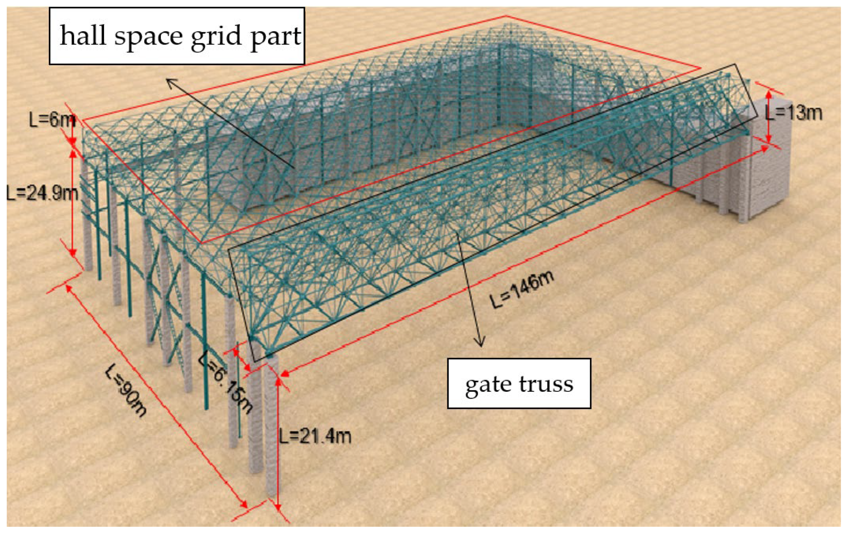
3.1. Engineering Background

Using the visualization of BIM technology, it is possible to establish a node position information model and make a construction simulation, visually express the complex composition of nodes, and predict problems that may arise during the construction process. Through BIM technology, the model of the maintenance hangar of Chengdu Tianfu International Airport is established in the BIMFILM 2.0 software, as shown in Figure 1. It consists of a hall space grid and a gate truss, with a total area of 13,140 m2. The hall space grid part is 6 m high, and the gate truss part is 13 m high. The roof has a plan size of 146 m × 90 m and is composed of many quadrangular cone space units. The quadrangular cone space unit in the structure consists of the upper chord, middle chord, lower chord, upper web, and lower web, with a plan size of 6 m × 6 m and a height of 6 m, and the nodes are all welded hollow ball nodes. The lower chord center height of the hangar roof hall space grid is 24.9 m, the lower chord center height of the hangar gate truss is 21.4 m, and the roof is supported by peripheral concrete columns. A gate truss is set on the opening edge.

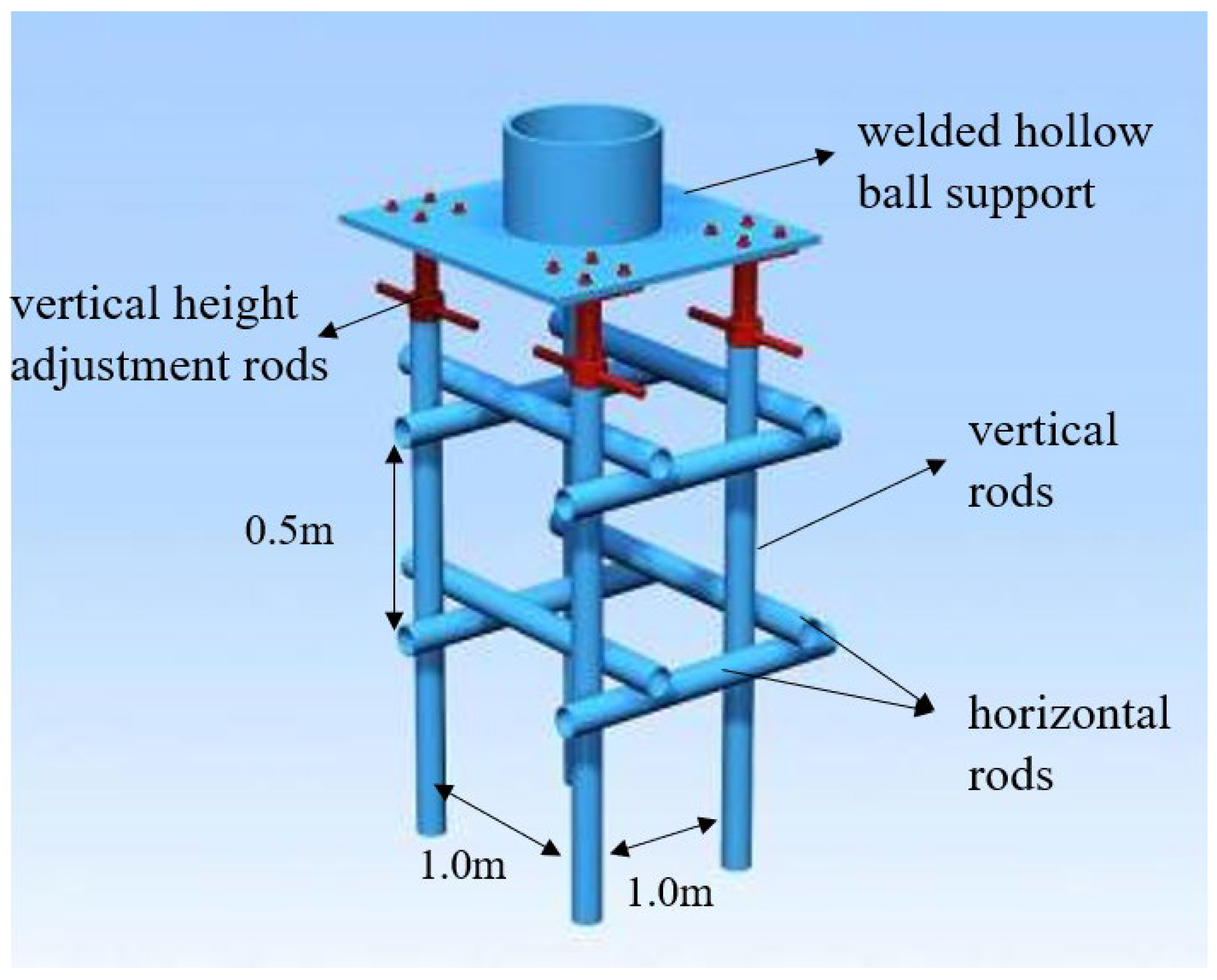
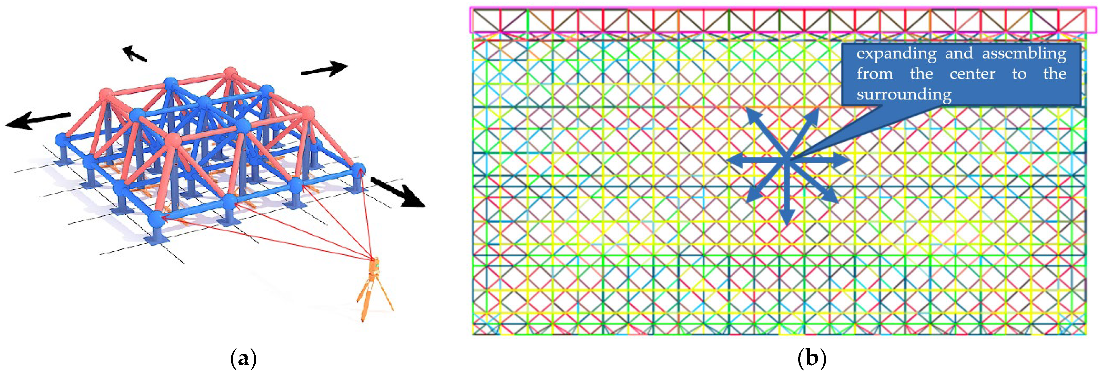
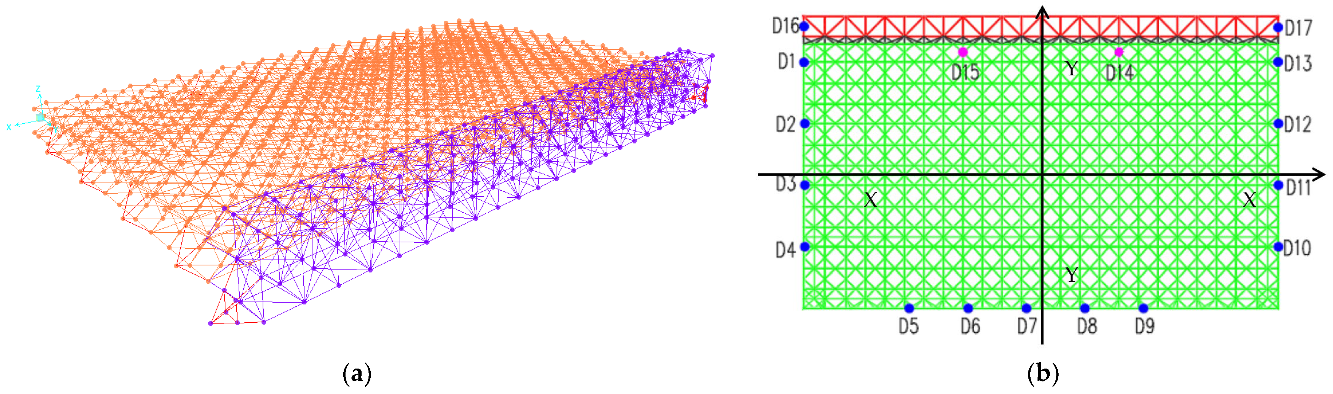
3.2. Preparation for Lifting

Assembling and welding are required before the spatial grid is lifted. The roof space grid should be partially assembled on a specially assembled tire frame first. As shown in Figure 2, the assembled frame is composed of a welded hollow ball support, vertical height adjustment rods, vertical rods, horizontal rods, and connection fasteners.
Figure 3 shows the welding process of the grid via BIM technology. The sequence of “expanding and assembling from the center to the surrounding” should be adopted when the grid frame is welded and assembled. The rods in the central area of the grid are welded first, and then, the welded rods are used as a new starting point to gradually expand and assemble in all directions.
The hall space grid in the maintenance hangar of Chengdu Tianfu International Airport consists of a three-layer plane grid connected by web members. Figure 4 shows the specific assembly steps of the hall space grid frame via BIM 2.0 software.
After the completion of the assembly of the hall space grid part on the ground, using the mechanical analysis software SPA2000 combined with BIM technology, the mechanical analysis of the lifting point of the long-span spatial steel structure is carried out. The lifting construction of long-span spatial steel structures is simulated, the most unfavorable working conditions are found, and a safe and effective construction plan is adopted. Figure 5a shows the structure information model established in SPA2000. When determining the lifting points for the structure, it is important to consider the stiffness of the structure. Whenever possible, the original supporting points of the structure should be used as lifting points, and the number of lifting points should be approximately half the number of supporting points. Additionally, since the structure is almost symmetrical, the lifting point configuration on one side can be mirrored on the other. As seen in Figure 5b, lifting points D1~D4 and D13~D10, as well as lifting points D16 and D17, are arranged symmetrically (the symmetry axis is Y–Y axis) in order to keep the balance of the spatial grid in the direction of the hangar opening. D14 and D15 are arranged near the one-third point of the hangar span, and together with D5~D9, the balance of the spatial grid in the depth direction of the hangar is maintained. Among all the lifting points, except for D14 and D15, which are arranged on the temporary tire frame, the rest of the lifting points are arranged on the concrete structure bearing column, which makes it possible to reduce the construction cost while ensuring a reasonable force of the grid structure.

3.3. Mechanical Analysis of the First Lifting Stage

Fifteen lifting points were set in the first lifting stage, numbered D1~D15, where D1~D13 were set on the nodes of the spatial grid corresponding to the temporary support frame on the top of the concrete bearing column, and D14 and D15 were set on the nodes of the spatial grid corresponding to the lattice lifting bracket within the gate span. The lifting points were set symmetrically about the centerline of the gate of the spatial grid to guarantee the balance of forces when the spatial grid was lifted. The schematic diagram of the arrangement of lifting points in the first lifting stage is shown in Figure 6.
During the first lifting stage, the lifting force was provided by the 15 lifting points from D1 to D15. Figure 7 shows the simulation results of the lifting force for each lifting point.
As seen in Figure 7, among the 15 lifting points in the first lifting stage, the lifting force of D4 is the smallest with a value of 223 kN, while the lifting force of D15 is the largest with a value of 1862 kN, provided by the lattice lifting bracket at the gate. The lifting points D1~D4 are located on the left side of the spatial grid, and the lifting points D13~D10 are located on the right side of the spatial grid, and they are symmetrically distributed about the centerline of the gate, with D1 corresponding to D13, D2 corresponding to D12, D3 corresponding to D11, and D4 corresponding to D10. From the lifting force of the nodes, it can be seen that the lifting force values of the lifting points, which are symmetrical about the center line of the gate, are relatively close to each other. This indicates that the pressure generated via the spatial grid on the lifting points also becomes symmetrically distributed, which is consistent with the actual force characteristics of the spatial grid and verifies the reasonableness of integral lifting.
The strength stress diagram of the first lifting stage of the spatial grid is shown in Figure 8. In the first lifting stage, the overall stress of the spatial grid is symmetrical about the center line of the gate, which is related to the symmetry of the spatial grid structure and the lifting point arrangement. The stress of the members around the lifting point is relatively high, and the maximum value of stress in the mesh is 155 MPa, which meets the requirements of the member-bearing capacity in the code [33]. So, the spatial grid is in a safe state.
Figure 9 shows the displacement cloud diagram of the first lifting stage of the spatial grid, and it can be seen from the figure that the displacement cloud diagram of the spatial grid is also symmetrical about the center line of the gate and shows a trend of gradually decreasing along the surrounding with the center as the starting point. The vertical displacement in the center of the spatial grid is the largest, with a maximum value of 132.9 mm.
According to the requirements of the code [34], the maximum vertical displacement of the spatial grid should meet Umax ≤ l0/250 (l0 is the short span of the spatial grid). In this study, the span of the spatial grid is 90 m, so Umax ≤ 90,000/250 = 360 mm. From the previous section, it is known that the maximum displacement of the spatial grid in the first lifting stage is 132.9 mm (less than 360 mm). Therefore, the integral lifting vertical displacement of the spatial grid in this study is within the design range and meets the specification requirements. However, it is still necessary to detect the maximum vertical direction in the center area of the spatial grid at any time during the actual spatial grid lifting construction and take certain measures to reduce the maximum vertical displacement to ensure the safety of the spatial grid lifting construction.
For the maximum horizontal displacement limit of the spatial grid, it can be determined via the horizontal displacement limit of the top of the concrete row frame column. According to relevant code [35], the horizontal displacement of the top of the row frame column should be less than H/30 = 21,400/30 = 713 mm (H is the height of the top of the row frame column). The maximum horizontal displacement of the spatial grid at this stage is 26.3 mm, which is less than 713 mm and meets the requirements of the code. Obviously, compared with the vertical displacement, the horizontal displacement of the spatial grid in the lifting process is very small, so the vertical displacement is the key monitoring object. Figure 10 shows the spatial steel roof structure during the lifting process, reflecting the practicality of the method and providing a scientific reference for future design and lifting construction.

3.4. Mechanical Analysis of the Second Lifting Stage

In the second stage, on the basis of the existing lifting points in the first stage, two lifting points D16 and D17 at the two ends of the gate truss are added. These two lifting points provide 3000 kN lifting force vertically upward, respectively, during the integral lifting, and the arrangement of lifting points in the second stage is shown in Figure 11.
As can be seen from Figure 12, the stress distribution of the internal members of the spatial grid is relatively uniform, and the distribution law is similar to that of the first lifting stage. The maximum stress in all the members is 165.6 MPa, which meets the code requirements. The vertical displacement cloud diagram of the second lifting stage of the spatial grid is shown in Figure 13. It can be seen that for the hall space grid part, the vertical displacement law is similar to that of the first stage. The displacement in the center of the hall space grid is the largest and shows the law of gradually decreasing from the center to the surroundings. For the gate truss part, the maximum displacement point is located in the middle of the span of the gate truss. And the maximum displacement of the roof is located in the middle of the span of the gate truss. Its maximum value is 176.5 mm (less than 360 mm). Therefore, the overall design of the roof grid structure meets the specification requirements.
Similarly, the maximum horizontal displacement of the spatial grid at this stage is 30.6 mm (less than 713 mm), which is in line with the specification requirements. Compared with the maximum value of vertical displacement, the horizontal displacement value of the spatial grid at this stage is also smaller, and the maximum value of vertical displacement is the key monitoring object during construction.
Figure 14 compares the lifting forces of the lifting points in the two stages, and the lifting forces of each lifting point were changed during the two stages of lifting construction. During the construction of the second lifting stage, the spatial grid was deformed due to the change in the structure form and the number of lifting points, which made the internal force of the spatial grid redistributed. The lifting force of the point (D2–D5 and D9–D12) with a larger lifting force in the first stage gradually decreases in the second stage, while the lifting force of the point (D1, D6–D8 and D13) with a smaller lifting force in the first stage gradually increases in the second stage. This makes the distribution of the internal force of the spatial grid more uniform. The lifting points symmetrically distributed in space have similar lifting forces. During the phased lifting construction, the maximum stress and maximum displacement of the spatial grid members in both stages meet the requirements of the relevant design codes.

4. Mechanical Performance Analysis of Asynchronous Integral Lifting

During the lifting process, there are factors such as wind changes, temperature changes, construction operations, hydraulic lifting control system delays, etc., which can cause the spatial grid to be lifted out of synchronization, thus leading to uneven distribution of internal forces in the spatial grid and excessive stress or displacement in some members. This will make the stability of the grid lifting and the safety of construction workers unable to be guaranteed. Studying the asynchronous lifting situation of the spatial grid during the lifting process and providing corresponding control measures can help ensure the smooth progress of the integral lifting and installation construction.
In the process of the integral lifting of the spatial grid, the displacement difference between the lifting points is random, and there are several combinations of displacement differences, so it is necessary to determine the most unfavorable working condition of the spatial grid when the combination of displacement differences acts and to analyze it numerically.

4.1. Mechanical Analysis of Single-Point Asynchronous Integral Lifting

According to the requirements of the penetrating jack, the allowable displacement difference between two adjacent lifting points is 1/250 of the distance between the two points and is less than 25 mm. In this study, the displacement difference of unsynchronized lifting is set to 20 mm, i.e., a 20 mm displacement difference is applied to the unsynchronized lifting points, while the displacement difference between the synchronized lifting points is set to 0.
A 20 mm displacement difference was applied to each of the 15 lifting points during the first lifting stage of the spatial grid, and then, a simulation analysis of the vertical deformation of the spatial grid was carried out. The vertical displacement cloud of the spatial grid was obtained, as shown in Figure 15, and the lifting force statistics of each lifting point are in Table 1.
From Figure 15, it can be seen that when there is a 20 mm displacement difference at a single lifting point, the displacement of the members near this point is significantly affected, while the displacement of the members farther away is almost unaffected. In addition, when a single lifting point has a displacement difference of 20 mm, the adjacent short members are affected to a greater extent than the long members.
As seen in Table 1, when a single lifting point has a displacement difference of 20 mm, it has a more obvious effect on the lifting force of adjacent lifting points, while it has a smaller effect on the lifting force of more distant lifting points.

4.2. Mechanical Analysis of Double-Point Asynchronous Integral Lifting

When the spatial grid is lifted asynchronously, the main consideration is the combination of the displacement difference between the lifting point and the neighboring points and between the lifting point and the interlaced point. The combination of the given lifting displacement difference is studied, and the results obtained are compared and analyzed with the calculation results of the displacement difference applied to a single lifting point only, in order to find the pattern of it.
Taking the combination of neighboring points (D7 and D8) and the combination of interlaced points (D7 and D9) as an example, a vertical displacement of 20 mm is applied to each combination of lifting points to simulate the vertical deformation of the spatial grid and the change in lifting force of lifting points under the combination action of double lifting point displacement difference.
A comparative analysis of the displacement of the spatial grid for single-point asynchronous integral lifting and double-point asynchronous integral lifting by Figure 14 and Figure 16 shows that when a 20 mm displacement difference is applied to the combination of neighboring points (D7 and D8) or the combination of interlaced points (D7 and D9), the influence area of vertical deformation is similar to the superimposed influence area when the displacement difference is applied to two points alone.
This also indicates that the displacement difference applied to the combination of neighboring points and the combination of interlaced points will affect the displacement of the spatial grid members near the lifting points, and then affect the internal force of the members.
Table 2 shows the lifting point lift forces for the combination of neighboring points (D7 and D8) and the combination of interlaced points (D7 and D9) with the dis-place-ment difference applied simultaneously and separately. When lifting points D7 and D8 are simultaneously applied with a 20 mm vertical displacement difference, the lifting force of the lifting point itself and its neighboring points (D6 and D9) are smaller than the lifting force when D7 and D8 are applied with 20 mm respectively, and the difference is not negligible. Although the lifting forces of the remaining lifting points are changed, the difference is negligible compared with the overall lifting force. The change in lifting force between lifting points D7 and D9 applied simultaneously and separately with a 20 mm vertical displacement difference is small. However, compared to applying the displacement difference separately, the lifting force of interlaced lifting point D8 was increased by 10.9% when the displacement difference was applied simultaneously. This is caused by the superimposed influence of the two lifting points, so its influence needs to be considered during the actual construction.
Thus, the influence produced by applying displacement difference to neighboring lifting points separately includes the influence of applying displacement difference at the same time, and the latter need not be considered separately. When the displacement difference is applied to the interlaced lifting point, the influence of the interlaced lifting point and its connected members cannot be ignored and should be included in the most unfavorable working conditions. The most unfavorable working conditions for asynchronous lifting of the spatial grid are shown in Table 3.
From the above analysis, it can be seen that the actual project in the construction of the safety verification should mainly consider the impact of the single-point asynchronous lifting displacement difference and the interlaced point asynchronous lifting combination displacement difference on the integral lifting of the spatial grid structure. The impact of the most unfavorable working conditions on the asynchronous lifting of the spatial grid structure is considered, and if the stress or displacement of the members in the most unfavorable working condition verification results do not meet the code requirements, the unqualified members should be reinforced or replaced to ensure the safety of the spatial grid structure.

5. Conclusions

This research proposes a time-varying mechanical analysis of the synchronous and asynchronous integral lifting and a single and interlaced point’s asynchronous integral lifting analysis method of a long-span spatial steel structure. The adverse effects of the displacement difference between lifting points with asynchronous integral lifting and have been displayed in construction with BIM and numerical simulation. In the case of asynchronous lifting of a single point, the displacement influence on other members is related to the distance. The closer the distance from the lifting point, the greater the influence. Under the condition of the same distance, it has a great influence on the short rod and a small influence on the long rod. In the process of structural lifting, it is necessary to pay attention to the lifting order of each lifting point. The detached lifting can be carried out according to the statistical results. In the process of lifting, the lifting point with a small lifting force should be lifted first, and then, the lifting point with a large lifting force should be lifted. In asynchronous integral lifting, the order of lifting points should be opposite to the ascending order. The lifting point with a large lifting force is first installed in the specified position, and the lifting point with a small lifting force is installed in the specified position.

Author Contributions

Conceptualization, G.Y. and Y.Y.; methodology, G.Y.; software, H.D. and X.M.; validation, G.Y. and Y.Y.; formal analysis, Y.Y. and W.M.; investigation, H.D. and X.M.; resources, G.Y.; data curation, H.D. and W.M.; writing—original draft preparation, H.D. and Y.Y.; writing—review and editing, G.Y. and Y.Y.; visualization, H.D.; supervision, G.Y.; project administration, G.Y.; funding acquisition, G.Y. and Y.Y. All authors have read and agreed to the published version of the manuscript.

Funding

This work was funded by the National Key R&D Program of the Ministry of Science and Technology (No. 2019YFD1101005-4), the National Key Research and Development Program of China (2021YFC3100300) and the Basic Scientific Research Business of Central Universities (2023CDJXY-031).

Institutional Review Board Statement

Not applicable.

Informed Consent Statement

Not applicable.

Data Availability Statement

The data presented in this study are available on request from the corresponding author.

Conflicts of Interest

The authors declare no conflict of interest.

References

  1. Tian, L.; Hao, J.; Wei, J.; Zheng, J. Integral lifting simulation of long-span spatial steel structures during construction. Autom. Constr. 2016, 70, 156–166. [Google Scholar] [CrossRef]
  2. Guo, H.; Zhou, Y.; Pan, Z.; Zhang, Z.; Yu, Y.; Li, Y. Automated Selection and Localization of Mobile Cranes in Construction Planning. Buildings 2022, 12, 580. [Google Scholar] [CrossRef]
  3. Azami, R.; Lei, Z.; Hermann, U.; Zubick, T. A Predictive Analytics Framework for Mobile Crane Configuration Selection in Heavy Industrial Construction Projects. Buildings 2022, 12, 960. [Google Scholar] [CrossRef]
  4. Guo, T.; Wu, E.; Li, A.; Wei, L.; Li, X. Integral lifting and seismic isolation retrofit of great hall of Nanjing Museum. J. Perform. Constr. Facil. 2012, 26, 558–566. [Google Scholar] [CrossRef]
  5. Deng, N.; Wei, J.; Deng, Y. Simulation of Construction Process Combining Steel Truss Integral Lifting with Concrete Pouring for SRC Conversion Layer Structure. In Proceedings of the 2016 International Conference on Architectural Engineering and Civil Engineering, Shanghai, China, 9–11 December 2016; pp. 75–79. [Google Scholar]
  6. Yaozhi, L.; Ning, H.; Xiao-guang, C. Deployable integral lifting construction technology for cylindrical latticed shells. Prog. Steel Build. Struct. 2005, 7, 27–32. [Google Scholar]
  7. Zhang, H.; Zhang, Y.T.; Zhu, H.; Gao, J.B. Research on Integral Lifting Continuous Steel Box Girder Bridge Construction Technology. In Proceedings of the Applied Mechanics and Materials, Hong Kong, China, 17–18 August 2013; pp. 1674–1681. [Google Scholar] [CrossRef]
  8. Zhang, H.; Zhou, R.Z. Research on Lifting Techniques of Large Segments of steel box girder of Chongqi Bridge. Adv. Mater. Res. 2012, 446–449, 1094–1098. [Google Scholar] [CrossRef]
  9. Xu, J.H. Truss construction of green fabricated steel structure based on BIM intelligent technology. Int. J. Crit. Infrastruct. 2021, 17, 54–70. [Google Scholar] [CrossRef]
  10. Yu, J.Y.; Wang, J.F.; Hua, Z.M.; Wang, X.X. BIM-based time-cost optimization of a large-span spatial steel structure in an airport terminal building. J. Facil. Manag. 2022, 20, 469–484. [Google Scholar] [CrossRef]
  11. Chen, S.X.; Wu, J.; Shi, J.L. A BIM Platform for the Manufacture of Prefabricated Steel Structure. Appl. Sci. 2020, 10, 8038. [Google Scholar] [CrossRef]
  12. Li, F.H.; Wang, Z.S.; Pang, C.A.; Yang, H.P. 3D Modeling of Mine Protection Complex Steel Structure Based on BIM Technology. J. Appl. Math. 2023, 2023, 7193935. [Google Scholar] [CrossRef]
  13. Zhu, Y.; Gao, Y.; Zeng, Q.; Liao, J.; Liu, Z.; Zhou, C. Real-Time Structural Monitoring of the Multi-Point Hoisting of a Long-Span Converter Station Steel Structure. Sensors 2021, 21, 4737. [Google Scholar] [CrossRef] [PubMed]
  14. Lu, Y.; Zhang, C.Y. Dynamic Data Monitoring of Building Information of Nano-Modified Building Steel Structure Materials Using BIM Model. Integr. Ferroelectr. 2021, 216, 197–213. [Google Scholar] [CrossRef]
  15. Xia, Y. Research on dynamic data monitoring of steel structure building information using BIM. J. Eng. Des. Technol. 2020, 18, 1165–1173. [Google Scholar] [CrossRef]
  16. Hu, S.; Fang, Y. Automating crane lift path through integration of BIM and path finding algorithm. In Proceedings of the ISARC, International Symposium on Automation and Robotics in Construction, Kitakyushu, Japan, 26–30 October 2020; pp. 522–529. [Google Scholar]
  17. Zhu, A.; Zhang, Z.; Pan, W. Crane-lift path planning for high-rise modular integrated construction through metaheuristic optimization and virtual prototyping. Autom. Constr. 2022, 141, 104434. [Google Scholar] [CrossRef]
  18. Tian, J.H.; Luo, S.; Wang, X.M.; Hu, J.; Yin, J. Crane Lifting Optimization and Construction Monitoring in Steel Bridge Construction Project Based on BIM and UAV. Adv. Civ. Eng. 2021, 2021, 5512229. [Google Scholar] [CrossRef]
  19. Lacey, A.W.; Chen, W.; Hao, H.; Bi, K. Structural response of modular buildings—An overview. J. Build. Eng. 2018, 16, 45–56. [Google Scholar] [CrossRef] [Green Version]
  20. Kang, S.; Miranda, E. Planning and visualization for automated robotic crane erection processes in construction. Autom. Constr. 2006, 15, 398–414. [Google Scholar] [CrossRef]
  21. Guo, Y.L.; Tian, G.Y.; Wang, X.A.; Chen, G.D.; Fan, F. Research and Application of Time-Variation Analysis and Key Control Technology in Complex Steel Structures Construction. Adv. Mater. Res. 2012, 368–373, 2319–2326. [Google Scholar] [CrossRef]
  22. Li, Q.; Wang, C.; Ellingwood, B.R. Time-dependent reliability of aging structures in the presence of non-stationary loads and degradation. Struct. Saf. 2015, 52, 132–141. [Google Scholar] [CrossRef]
  23. Tian, L.; Hao, J. Nonlinear time-varying analysis algorithms for modeling the behavior of complex rigid long-span steel structures during construction processes. Steel Compos. Struct. 2015, 18, 1197–1214. [Google Scholar] [CrossRef]
  24. Tian, L.; Hao, J.; Li, C.; Wang, Y. Simulation analysis on integral lifting of large-span steel roof structures during construction process. J. Build. Struct. 2013, 34, 33–39. [Google Scholar] [CrossRef]
  25. Wang, Z.; Ren, W.; Chen, G. Time–frequency analysis and applications in time-varying/nonlinear structural systems: A state-of-the-art review. Adv. Struct. Eng. 2018, 21, 1562–1584. [Google Scholar] [CrossRef]
  26. Hajjar, D.; AbouRizk, S.M. Unified modeling methodology for construction simulation. J. Constr. Eng. Manag. 2002, 128, 174–185. [Google Scholar] [CrossRef] [Green Version]
  27. Agkathidis, A.; Brown, A. Tree-Structure Canopy: A Case Study in Design and Fabrication of Complex Steel Structures using Digital Tools. Int. J. Archit. Comput. 2013, 11, 87–104. [Google Scholar] [CrossRef]
  28. Huang, T.; Kong, C.W.; Guo, H.L.; Baldwin, A.; Li, H. A virtual prototyping system for simulating construction processes. Autom. Constr. 2007, 16, 576–585. [Google Scholar] [CrossRef] [Green Version]
  29. Case, F.; Beinat, A.; Crosilla, F.; Alba, I.M. Virtual trial assembly of a complex steel structure by Generalized Procrustes Analysis techniques. Autom. Constr. 2014, 37, 155–165. [Google Scholar] [CrossRef]
  30. Guo, Y.; Miao, Y.; Lou, J.; Lin, B.; Xu, Y.; Cui, W. Integral lift design of the main trusses in Macao Gymnasium and analysis of the latticed hoist tower. Jianzhu Jiegou Xuebao (J. Build. Struct.) 2005, 26, 17–24. [Google Scholar]
  31. Liu, Y.P.; Chan, S.L. Second-Order and Advanced Analysis of Structures Allowing for Load and Construction Sequences. Adv. Struct. Eng. 2011, 14, 635–646. [Google Scholar] [CrossRef]
  32. Zheng, J.; Hao, J.P.; Zhong, W.H. The mechanics analysis and research of multi-suspension-centers integral lifting technology for long-span steel roof. Appl. Mech. Mater. 2012, 170–173, 3194–3198. [Google Scholar] [CrossRef]
  33. GB 50017-2017; Code for Design of Steel Structure. China Building Industry Press: Beijing, China, 2017.
  34. JGJ 7-2010; Technical Specification for Space Frame Structures. China Building Industry Press: Beijing, China, 2010.
  35. GB 50011-2010; Code for Seismic Design of Buildings. China Building Industry Press: Beijing, China, 2010.
Figure 1. The model and structural parameters of the maintenance hangar of Chengdu Tianfu International Airport.
Sustainability 15 11256 g001
Figure 2. Assembled tire frame structure diagram.
Sustainability 15 11256 g002
Figure 3. General order of welding: (a) schematic diagram of welding sequence of the small joint unit; (b) schematic diagram of the overall welding sequence.
Sustainability 15 11256 g003
Figure 4. Grid assembly flow chart: (a) coordinate measurement and installation of the assembled tire frame; (b) installation of the first layer of welded hollow balls; (c) Chord welding of the first layer; (d) web welding of the first layer; (e) chord and web welding of the second layer; (f) chord welding of the third layer.
Sustainability 15 11256 g004
Figure 5. Schematic diagram of grid: (a) overall grid structure in SPA2000; (b) the spatial grid lifting point layout.
Sustainability 15 11256 g005
Figure 6. Layout of the first lifting stage point.
Sustainability 15 11256 g006
Figure 7. The lifting force of each point in the first lifting stage.
Sustainability 15 11256 g007
Figure 8. Strength and stress cloud diagram of the first lifting stage of the spatial grid (GPa).
Sustainability 15 11256 g008
Figure 9. Vertical displacement cloud map of the first lifting stage of the spatial grid (mm).
Sustainability 15 11256 g009
Figure 10. Spatial steel roof structure in the lifting construction.
Sustainability 15 11256 g010
Figure 11. Layout of the second lifting stage point.
Sustainability 15 11256 g011
Figure 12. Strength and stress cloud diagram of the second lifting stage of the spatial grid (GPa).
Sustainability 15 11256 g012
Figure 13. Vertical displacement cloud map of the second lifting stage of the spatial grid (mm).
Sustainability 15 11256 g013
Figure 14. Two-stage lifting point lifting force comparison diagram.
Sustainability 15 11256 g014
Figure 15. Vertical deformation cloud map of single point lifting spatial grid (mm): (a) a 20 mm displacement difference imposed on lifting point D7; (b) a 20 mm displacement difference imposed on lifting point D8; (c) a 20 mm displacement difference imposed on lifting point D9.
Sustainability 15 11256 g015
Figure 16. Vertical deformation cloud map of double points lifting spatial grid (mm): (a) a 20 mm displacement difference imposed on lifting points D7 and D8; (b) a 20 mm displacement difference imposed on lifting points D7 and D9.
Sustainability 15 11256 g016
Table 1. Lifting force when a 20 mm displacement difference is imposed on a lifting point (kN).
Lifting Point NumberLifting Force (kN)
D1D2D3D4D5D6D7D8D9D10D11D12D13D14D15
D130359081623456471979578284923885464022818201865
D218175875022356372179177985023985863823018601852
D322857195215757171878577784923985163823018671855
D423264075329754671278977984923885464022918751854
D522963782520364664878678185023885464022918601861
D623564482121949886171777285123885263923118451862
D723864381622356464594270184723985164123518521850
D823564081822356870971193377823884964623518701835
D923264081922356671778670793421686363722818761841
D1023164082022356771678977882731178764022918651864
D1123263881722356671478677485917298856822618661856
D1223263881822356671679078584723878375917918631849
D1323064082022356571879478484823985059030018761809
D1414463482724656068076679287524286064025420791687
D1525664082522658373578574382526286163386116982068
Note: The thickened data indicate the lifting force of the lifting point with a 20 mm displacement difference.
Table 2. Lifting force when a 20 mm displacement difference is imposed on two lifting points (kN).
Lifting Point NumbersLifting Force (kN)
D1D2D3D4D5D6D7D8D9D10D11D12D13D14D15
D7-D823864381822356870994293384723985164623518701850
D7+D824264381422456663886585677523884664724118591833
D7-D923864381922356671793963093221786364123518761850
D7+D923864381622356470694270793423986163923418651840
Note: The thickened data indicate the lifting force of the lifting point with a 20 mm displacement difference. “-” indicates that the displacement difference is applied separately, and “+” indicates that the displacement difference is applied simultaneously.
Table 3. The most unfavorable conditions when the spatial grid is asynchronized lifting.
NumberWorking ConditionNumberWorking Condition
1D19D9
2D210D10
3D311D11
4D412D12
5D513D13
6D614D14
7D715D15
8D816D1 + D3 + D5 + D7 + D9 + D11 + D13
Disclaimer/Publisher’s Note: The statements, opinions and data contained in all publications are solely those of the individual author(s) and contributor(s) and not of MDPI and/or the editor(s). MDPI and/or the editor(s) disclaim responsibility for any injury to people or property resulting from any ideas, methods, instructions or products referred to in the content.

