Article

Optical Wireless Power Transfer for Implanted and Wearable Devices

International Institute for Carbon-Neutral Energy Research (WPI-I2CNER), and Institute of Mathematics for Industry (IMI), Kyushu University, Fukuoka 819-0385, Japan
Sustainability 2023, 15(10), 8146; https://doi.org/10.3390/su15108146
Submission received: 17 February 2023 / Revised: 15 May 2023 / Accepted: 16 May 2023 / Published: 17 May 2023
(This article belongs to the Special Issue Sustainable Technologies and Developments for Future Energy Systems)

Abstract

:
Optical wireless power transfer (OWPT) has been employed in the literature as a wireless powering approach for implanted and wearable devices. However, most of the existing studies on this topic have not studied the performances of OWPT systems when light is transmitted through clothing. This research therefore contributes to investigate the effects of clothing on OWPT performances from both theoretical and experimental perspectives. An obtained experimental result indicates that a single light-emitting diode (LED) transmitter is able to perform the OWPT through white cotton clothing, but failed with another dark cotton clothing, even at a small transmitting distance. Hence, this research proposes to employ LED arrays as optical transmitters to improve the OWPT system capability in terms of the wirelessly transmitted power, transmitting distance and system tolerance to misalignments, whilst keeping the system safety, low cost and simplicity. Consequently, a theoretical formula for the power transmission efficiency made by an LED array through clothing is proposed and then is verified with experimental results. Furthermore, the important role of multiple light reflections at the surfaces of clothing and the LED array transmitter is pointed out.

1. Introduction

Implanted devices, e.g., several types of biosensors, implanted cardiac pacemakers, etc., are very important for the continuous health monitoring and medical therapy. These devices are deployed at specific positions inside human bodies based on their purposes. Wearable devices, on the other hand, were initially made for entertainment purposes, but were then incorporated with functions to monitor and record user biomedical information, e.g., body temperature, heart rate, blood pressure, respiratory rate, etc. Wearable devices can be more flexibly located at different positions than implanted devices, e.g., wrist, ankle, chest, etc., since they are not inside human bodies. They can even be integrated into the clothing, which is in contact with human skin when being worn [1].
It is worth noting that implanted and many wearable devices are biomedical electronic devices whose purposes are to treat medical conditions, monitor health problems, and improve the quality of life for patients. This is a field bridging engineering, biology, and medical, with a recent trend of miniaturization. For such devices, the problem of powering them while keeping their mobility, convenience and functioning is a challenge [2,3,4,5]. Non-rechargeable batteries are traditionally embedded inside the body together with implanted devices to power them up. Nevertheless, such batteries must be replaced after a few years, hence requiring expensive surgeries and bringing discomfort to users [2]. Moreover, the wires utilized in traditional implant devices cause trouble for users, especially when users make strong moves [2]. For wearable devices, the immobility of a wired energy supply makes this powering method inconvenient and uncomfortable. Rechargeable batteries are usually employed to store energy for later use, however system weight and size will be increased, while the system aestheticism and user comfort may be reduced. Therefore, there has been an emerging trend of using wireless power transfer (WPT) technologies for supplying energy to implanted and wearable devices so that less or even no batteries are needed.
WPT, as its name indicates, is a general methodology of transmitting power and energy from one point to another without using any wires between those points. This concept was first proposed by Nikola Tesla in the 1890s using electromagnetic fields, which, although it was not completely successful, inspired many other scientists until now to follow and develop further such idea. Hitherto, WPT is being investigated worldwide using different technologies, which can be grouped into short-range and long-range categories, see, e.g., [6,7]. WPT is also considered to be an emerging approach for many practical systems in transportation, energy systems, and their interconnections, or in manufacturing, Internet of Thing (IoT) systems, etc. [8].
OWPT is one of the most suitable WPT methods for wireless powering of implanted and wearable devices, because of its several advantages at small sizes [3,4]. Those advantages include higher efficiency, more stable output, lighter weight, etc. [9,10,11]. In addition, OWPT can be combined with optical communication to wirelessly send out useful biomedical information [11,12]. At small system sizes such as that of implanted and wearable devices, the other WPT technologies, e.g., microwave, inductive, capacitive, and resonant inductive WPT, have significantly lower efficiencies than OWPT [2,5,11]. In addition, OWPT offers higher transmitting distances than other WPT technologies. Thus, recently OWPT has gained much attention, not only for implanted and wearable devices, but also for other devices and applications. For instance, perovskite optical transceivers were proposed and studied in [13,14] to create bidirectional OWPT systems that have great potentials for many applications and for improving the sustainability and socioeconomics [8].
The current work studies the performances of OWPT for implanted and wearable devices, in which solar cells, the optical receivers, are put on skin. Output power from solar cells can be supplied to implanted devices via a number of methods, e.g., using microneedles [15,16] as tubes holding wires, on-skin electrodes [17,18,19,20], etc. This makes our work different from other OWPT studies for implanted and wearable devices, where solar cells or photodiodes are under skin. The underlying reasons for putting solar cells on skin surfaces are as follows. First, system installation and maintenance are simplified, since only implanted devices and connecting wires are under the skin, whereas other system components such as solar cells, electronic devices, etc., are on the skin. As a result, the system cost is reduced. Second, the system’s energy efficiency is higher, because light does not need to travel through under-skin layers. Additionally, third, concerns on the toxicity of system components to human bodies including solar cells, batteries, etc., can be avoided. Last but not least, deploying solar cells on skin allows us to unify the research on OWPT for both implant and wearable devices, whereas embedding solar cells under skin causes extra challenges for implanted devices, as mentioned above.
Note, however, that using on-skin solar cells for implanted and wearable devices has a few limitations. First, technologies to connect on-skin solar cells to implanted devices are needed, which is not trivial. Second, on-skin solar cells may not be stylish, and hence, may affect the confidence of users. Therefore, tiny, thin and flexible on-skin solar cells should be developed in the future to achieve users’ satisfaction, perhaps in a similar manner as that of tattoos.
To this end, the employed optical transmitters and receivers in our research are LEDs and solar cells, respectively. Note that a laser is another light source that can be used for optical transmitters, but there are tradeoffs one needs to pay attention to when using lasers. First, laser output is a focused light beam with high intensity, hence the OWPT system energy efficiency can be higher, but the system safety under laser irradiation must be guaranteed. Second, a perfect alignment between laser transmitters and optical receivers is often required due to the small width of laser beams, which certainly limits the system mobility. To overcome this disadvantage, receiver tracking approaches or optical lenses may be used, but the system complexity, size, weight, and cost are increased. Therefore, only LEDs are considered as the optical transmitters in the current research, owing to their spread light beams and their safety. Having a diverged output beam leads to a bigger light covering area of an LED at a longer distance, hence providing a better tolerance to the misalignment between it and an optical receiver. Additionally, using LEDs as optical transmitters is a natural and low-cost approach for wirelessly powering implanted and wearable devices, since there are already many existing indoor LED lighting systems.
The existing studies on OWPT for implanted and wearable devices considered various system issues and properties, e.g., the optimal under-skin location of solar cells [21], the fusion of wearables with artificial intelligence (AI) and IoT [22], or just the optical properties of skins and tissues [23,24,25,26,27]. However, there have been a few works on OWPT for implanted and wearable devices considering clothing environments. Note that there has been an analytical mathematical formula in the literature for the DC gain of the optical path, see, e.g., in [13,14], but such a formula is only applicable for OWPT transmission in the air and is unusable for OWPT through clothing environments. A few preliminary results were reported in [28,29], when the solar cell receiver was covered by a white cotton shirt, under the illumination of a single LED.
There have been a few existing works on OWPT for implanted and wearable devices using LED arrays, e.g., [9,10,11]. Nevertheless, only the formula for the DC gain of the optical link established by a single LED was used in [9] for implanted solar cells and micro LED arrays. OWPT through clothing was not the case in [9]. On the other hand, no theoretical investment on the DC gain of the optical link created by an LED array was considered in [10,11].
The current research improves the studies in [28,29] by employing an LED array as the optical transmitter and investigating clothing with different color patterns. The obtained improvements are in terms of the wirelessly transmitted power, transmitting distance and system tolerance to misalignments, while keeping the system safety, low cost and simplicity.
The main contribution of the current work is a novel analytical mathematical formula to estimate the OWPT power transmission efficiency through clothing, where the OWPT is conducted with an LED array and the solar cell receiver is put on skin. More specifically, this research proposes that the reflection coefficient of the clothing material is a function of the distance between the LED array and the clothing. As will be demonstrated through experimental results, such a relation is especially critical at the short transmitting distances where the reflection becomes a dominant factor. The proposed theoretical formula on the reflection coefficient as well as the illustrative experiments have not been reported in the literature so far, to the best of the author’s knowledge, thus clearly show the novelty and contribution of the current research.
The remainder of this paper is as follows. Research methods are introduced in Section 2. Then, the experimental results and their related discussion are presented in Section 3. Lastly, conclusions are given in Section 4.

2. Methods

This sections presents the theoretical and experimental methods employed in the current study. In particular, theoretical backgrounds underlying the LED-based OWPT systems are first introduced. Then, the equipment used in the realistic OWPT experiments in Section 3 is provided.

2.1. Theoretical Backgrounds

There are basically three components in an OWPT system, which are the optical transmitter, the optical receiver, and a transmitting environment. As mentioned above, we are considering OWPT for implanted and wearable devices, in which solar cells, the optical receivers, are on skin. In reality, such solar cells are often covered by clothing. Therefore, the environment for OWPT here consists of the atmosphere and the clothing, as illustrated in Figure 1. There may be additional components in the system, e.g., optical lenses, leading to more environments to be considered. Nevertheless, in the current work, we only consider the atmosphere and the clothing as the transmission environments.
For employing a WPT technology to a specific application, various factors need to be considered including the system efficiency, safety, economy, complexity, size and transmission range. This section is aimed at presenting an estimation for the energy efficiency of an OWPT system. Let η r and η t denote the energy efficiency of the optical receiver and the optical transmitter, while η c and η a represent the energy transmission efficiency through the clothing and the air, respectively. The OWPT system energy efficiency, denoted by η s y s , is then calculated by:
η s y s = η t × η r × η a × η c
When the optical transmitter is a single LED, the following formula for the line of sight (LOS) optical link DC gain in free space can be used [13,14,30].
η a = m l + 1 A 2 π d 2 cos m l ϕ cos φ : 0 φ φ w                           0 : φ > φ w
The notations in Equation (2) are as follows. The optical receiver physical area and the transmission distance are denoted by A and d, whereas the angle of incidence and the angle of irradiance are represented by φ and ϕ , respectively. The width of the field of view (FOV) at the optical receiver is denoted by φ w . Next, the order of Lambertian emission is denoted by m l computed by m l = ln 2 ln cos Φ 1 / 2 , where Φ 1 / 2 is the LED’s half illuminance. Note that the non-LOS optical link DC gain is omitted for simplicity.
Noted that a single LED has a low output power and a limited illuminating region. Hence, the received wireless power at the receiver side could be low or even zero if the transmitting distance is long, or if there exist misalignments between the transmitter and the receiver. Therefore, to inherit the benefits of the safety and low cost of LED-based OWPT systems, while improving the amount of received wireless power and the system tolerance to transmitter–receiver misalignments, in this research LED arrays are used as optical transmitters. Accordingly, Equation (2) is valid for the optical link DC gain of each LED in the array. Then, if the optical receiver is within the illumination areas of several LEDs, the optical receiver output power will be the sum of the output powers obtained by individual LEDs. Assume that there are n LED transmitters whose illumination areas cover the solar cell. Then, the optical link DC gain obtained by an LED array is as follows:
η a = i = 1 n m l , i + 1 A 2 π d i 2 cos m l , i ϕ i cos φ i
where i is the LED transmitter index, and the variables in Equation (3) have the same meaning as that in Equation (2). Those variables as well as the OWPT system in this context are illustrated in Figure 2.
Next, the order of Lambertian emission of individual LEDs in an LED array is usually the same, so the notation can be reduced to m l for all LEDs. Assume furthermore that the planes of the LED array and the solar cell are parallel. Then, Equation (3) is simplified to be the following:
η a = m l + 1 A 2 π i = 1 n 1 2 π d i 2 cos m l + 1 ϕ i
because in this case ϕ i = φ i .
Consequently, the energy efficiency η c of OWPT through clothing can be approximated by the optical transmittance of the clothing material. Alternatively, η c can be estimated as the ratio between the transmitted and received radiant fluxes (W). For the latter method, the Beer–Lambert law and its modification are commonly utilized [31,32,33], as shown in Equation (5).
η c = 1 R 2 e μ c l
The variables in Equation (5) are as follows. The reflection and attenuation coefficients are denoted by R and μ c , respectively, and the clothing thickness is represented by l . Note that the refractive index of the clothing material is implicitly indicated through the reflection and attenuation coefficients R and μ c . Some studies in the literature ignored the reflection, i.e., the term 1 R 2 is omitted in Equation (5), whereas some others utilized just 1 R instead of 1 R 2 . The scattering of light when being transmitted through the clothing material is included in the attenuation coefficient μ c (m−1). Thus, μ c captures various characteristics of clothing materials and can be utilized to distinguish distinct material types. Nevertheless, it should be noted that Equation (5) is applicable only for estimating the OWPT efficiency from a single LED to a single optical receiver at the normal illuminating direction. In the case of multiple LED transmitters such as those in an LED array, Equation (5) is no longer held. Hence, we propose the following formula in Equation (6) to estimate the OWPT efficiency through an environment, e.g., clothing, conducted by an LED array, or multiple optical transmitters in more general contexts.
η c = 1 R h 2 e μ c l
In Equation (6), R h is the reflection coefficient of the clothing, which depends on the distance h along the normal direction between the LED array and the solar cell. This is due to the variance of the angle of incidence between the LEDs and the solar cell when the distance h is changed, and the thickness of the clothing is very small compared to h . Furthermore, the dependence of the reflection coefficient on the transmitting distance will capture the phenomenon of multiple reflections between the LED array and the clothing surface, as will be shown via experimental results in Section 3.2. This has never been reported in the literature so far, and hence obviously constitutes the novelty of the current study.

2.2. Experimental Methods

A commercial silicon solar cell with the dimensions 25 mm × 25 mm × 3 mm is utilized as the optical receiver in all experiments, as shown in Figure 3a. The output of this solar cell is connected to a DC-DC voltage boost controller before being connected to a small indicating LED for visualization, i.e., it is ON if OWPT is successful, and is OFF otherwise.
In the first experiment, the optical transmitter is a single white LED (Panasonic Corp.) consuming 100 V and 7.1 W, as depicted in Figure 3b. Moreover, for illustration of OWPT to implanted and wearable devices covered by clothing, a commercial cotton white shirt is used.
In the second experiment, a commercial color mixing cotton shirt is employed to demonstrate the effect of different color patterns to the whole OWPT system efficiency. Additionally, a stronger light source is utilized as the optical transmitter, which is composed of an array of white LEDs and is also commercially available, as exhibited in Figure 4. This LED array contains a row of 25 small LEDs covered by a plastic pane with a length of 26 cm. Moreover, the LED array can change its position in three dimensions, due to a connected structure with 6 degrees of freedom, as seen in Figure 4.

3. Results and Discussions

In this section, OWPT results from both simulations and realistic experiments are reported and compared. Particularly, OWPT at different transmitting distances, under different transmitting environments, and using different light sources are presented. Extensive discussions and analysis on experimental results are also given.

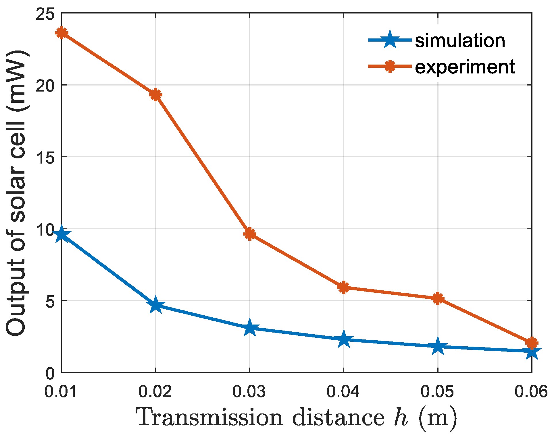
3.1. Simulation Results

This section introduces simulation results for the proposed theoretical formulas presented in Equations (4) and (6) for the OWPT efficiencies obtained by an array of LEDs. First, the power distribution of a single LED is provided for comparison with that of an LED array. LED data in [30] are used for simulations and are summarized in Table 1.
Consequently, the simulation result for a single LED is exhibited in Figure 5, depicting its power distribution at a distance of 6 cm and in an area of 0.5 m × 0.5 m, where the LED is put perpendicular to the origin and the solar cell described above is employed as the optical receiver. As observed in Figure 5, the LED power distribution is in the form of a cone. As long as a solar cell is inside the LED illumination area, an OWPT is made between the LED and the solar cell, and hence, a perfect alignment between them is not required. Therefore, this LED-based OWPT system can provide a better tolerance to misalignments between optical transmitters and receivers than that of laser-based OWPT systems. In addition, this LED-based OWPT system allows the mobility of the implanted and wearable devices, since they still wirelessly receive power inside the LED illumination area.
Next, with the same parameters of the LED given in Table 1 and the same solar cell optical receiver, we proceed to simulate the power transmitted by a row of 25 small LEDs, as that of the optical transmitter in Figure 4, to the solar cell located centrally to the LED array. The associated simulation results are provided in Figure 6, which show that the longer the distance is, the lower power can be received. Moreover, such a power decrease seems to be at an exponential speed, as shown in log scale in Figure 6.
In order to see how the received power looks when the location of the solar cell is changed, the power distributions over a plane of 0.5 m × 0.5 m by the above-considered LED row are shown in Figure 7 and Figure 8 at the transmitting distances of 3 cm and 6 cm, respectively. Those power distributions can be seen to be quite different, where almost the same amount of power can be received along the y-axis at the smaller transmitting distance, while the received power is maximum at the origin and is nonlinearly reduced at other positions at the longer transmitting distance. Hence, transmitting distance is an important parameter in the considered OWPT system with an LED array.
Additionally, the power distribution of an LED row in Figure 8 is also different from that of a single LED depicted in Figure 5 at the same distance of 6 cm and the same LED parameters. First, the amount of wireless optical power that can be delivered with the LED row is much higher than that with a single LED, but is not proportional to the number of LEDs, due to the nonlinear efficiencies given in Equations (2) and (4). Second, the illumination area of the LED row is bigger than that of a single LED, which is understandable due to the arrangement of LEDs in a straight row.

3.2. Experimental Results

In this section, the results of the two experiments described in Section 2.2 are presented. In the first experiment, more details on the obtained data are provided than in the previous studies [28,29]. This experiment is performed in free space and under a white cotton shirt.
For free-space OWPT, as depicted in Figure 9a, the indicating LED is still on when the distance between the LED and the solar cell is increased up to 30 mm. However, in the case of OWPT under the white cotton shirt, as depicted in Figure 9b, the maximum transmitting distance so that the indicating LED is still on is just 7 mm. Detailed results of the first experiment are shown in Table 2 at zero transmitting distance.
Certainly, the OWPT performance in free space is much better than that under clothing, evidenced through the received power and the power density, indicating that the used cotton material has a low optical transmittance. More specifically, the under-clothing OWPT efficiency in this scenario is around 42% of that in free-space. This is consistent with other experimental measurements on the optical transmittance of cotton materials, e.g., those reported in the study [31]. The results in [31] showed that an undyed cotton material with 400 μm thickness has an optical transmittance smaller than 40% and about 0.2 to 0.5% in the visible and the infrared (IR) ranges, respectively. Furthermore, the received power density shown in Table 2 is within the acceptable ranges for implanted and wearable devices [2,3,4]. Hence, the feasibility of OWPT for implanted and wearable devices with on-skin solar cells and LED light sources is shown.
If the white cotton shirt in the first experiment above is replaced by another cotton shirt having a white–dark-gray color mixing pattern, or the transmitting distance is longer than 30 mm, then the OWPT efficiency through the new shirt is very low with the single LED used in Figure 9. Therefore, a new light source, shown in Figure 4, is employed in the second experiment, which is a 100 V 11 W desk lamp with a row of 25 LEDs, as described in Section 2.2. The distance between two LEDs is 1 cm. With this new optical transmitter, the maximum transmitting distance in free-space is now increased to be 160 mm, much further than that of a single LED, shown in Table 2.
To show the advantages of employing an LED array composed of many LEDs as the optical transmitter, additional experiments are carried out, as illustrated in Figure 10, Figure 11 and Figure 12. The distance between the LED array and the solar cell in Figure 10 is set at 1.5 cm. In Figure 10a, two objects with the thickness of 1.5 cm are used to surround the solar cell while blocking the light from most of LEDs except the two LEDs on top of the solar cell. On the other hand, in Figure 10b, no obstacles exist between the LED array and the solar cell. Accordingly, the solar cell output power is higher when being illuminated by more LEDs, as shown below:
  • Solar cell output power in Figure 10a: 10.45 mW;
  • Solar cell output power in Figure 10b: 18.65 mW.
Similar results are obtained when the transmitting distance is longer. Thus, using more LEDs in the optical transmitter is beneficial in terms of increasing the received wireless power. Note, however, that the wirelessly transmitted power does not scale linearly with the number of LEDs, because at a short transmitting distance as in Figure 10, not all LEDs can directly illuminate on the solar cell.
Figure 11 and Figure 12, on the other hand, demonstrate the impressive system tolerances to transmitter–receiver misalignments, where the OWPT system still works well as the LED array is rotated 30 degrees along the normal direction to the receiver’s plane in Figure 11, or 75 degrees along the horizontal axis in Figure 12. Such tolerances of the OWPT system cannot be achieved with a single LED, e.g., that was used in Figure 3b and Figure 9, where a slight movement of the single LED from the normal direction to the solar cell can result in an unsuccessful OWPT. This again confirms the need and advantage of using an LED array over a single LED as an optical transmitter in OWPT systems.
Due to the existence of different color patterns in the newly used cotton shirt, the optical transmittance of this shirt is non-uniform. Hence, we would like to verify the OWPT efficiency associated with different color patterns. Illustrations for the experiment setups are given in Figure 13. Consequently, the efficiency of OWPT in the second experiment can be clearly observed via Figure 13a,b. More specifically, a much higher efficiency is obtained when OWPT is conducted through a white pattern than that through a gray or dark pattern at the same distance h , which is visually exhibited by the brightness of the indicating LED.
Details on the results of this experiment are depicted in Figure 14, obviously showing the differences on the OWPT efficiency in free space and under different color patterns. Particularly, OWPT in free space is much better than through clothing, and the OWPT efficiency through the white color pattern is highest for the considered clothing followed by the gray and dark patterns, respectively. This is explainable, because the gray and dark patterns absorb more light than the white pattern. In combination with the results presented in Figure 9 and Table 2 for OWPT using a single LED, it can be concluded that clothing with a white color and highly porous materials is most suitable for a high-efficiency OWPT system for under-clothing wearable and implanted devices.
To explain the above observation, we first take the natural logarithm for both sides of Equation (6), which results in
log η c = μ c l + 2 log 1 R h
Since the thickness of the used clothing is very small compared to that of the solar cell and compared to the OWPT transmitting distance, we can estimate η c by the ratio between the solar cell output when it is put under the clothing and that when no clothing is used. Hence, Equation (7) can be employed to accommodate the obtained experimental results. Note that it is difficult in this experiment to measure the light reflection from the clothing surface, because the existence of the LED array hinders a proper setup for such light reflection measurement. Therefore, we could not measure R h . However, the ratios of the solar cell output power under different color patterns to that in free space, displayed in Figure 15, shows that they vary quite largely and tend to come closer to zero as the transmission distance h is longer. Therefore, using Equation (7), it can be deduced from Figure 15 that μ c l is small for the investigating mix-color cotton clothing, i.e., its attenuation coefficient is small, compared to its reflection, at small distance h . As h is increased, R h 0 , leading to log 1 R h 0 , and hence, μ c l dominates.
Having the experimental results presented in Figure 14 and Figure 15, it is meaningful to see how the considered OWPT system would work with a realistic implanted device. Let us consider a pacemaker, a typical implanted device, as an example, which is powered by a 830 mAh lithium-iodine battery and consumes about 284 μAh daily [34]. Then, the charging times to fulfill the daily power need and to fully charge the battery using the considering OWPT system are depicted in Table 3.
Next, we show in Figure 16 the comparison on the solar cell output with free-space OWPT between the simulation of the theoretical formula in Equation (4) and the experimental measurements. More specifically, we assume that the used solar cell has a power conversion efficiency (PCE) of 17%, which is quite common for cheap, commercial silicon solar cells. All other specifications of the LEDs are the same as those provided in Table 1.
As observed in Figure 16, the measured solar cell output is much higher than the simulated one at very small transmitting distances, but tends to approach each other when the transmitting distance is longer. There could be several reasons for such a difference between the simulated and experimental results. The first reason is the multiple reflections back and forth between the LED surface and the surface surrounding the solar cell. Such reflections are stronger at shorter transmitting distances, hence requiring more studies on the light reflection at clothing surfaces. Another possible reason is due to the characteristics of the solar cell and other electronic components attached to the optical receiver.
Subsequently, given clothes with the same color patterns and material type, it can be intuitively predicted that the porosity of clothing material will greatly affect its optical transmittance. More specifically, the higher porosity a clothing material is, the higher optical transmittance it possesses, and hence, the higher OWPT efficiency for wearable and implanted devices can be obtained. In addition, given a clothing material, its transmittance of different light wavelengths could be different, hence it would be interesting to find a specific wavelength at which a high optical transmittance could be achieved for many common clothing materials. Those points will be carefully verified through experiments and will be reported in a future work.
All the obtained results described above show the feasibility of OWPT using LED arrays and solar cells for wireless powering of implanted and wearable devices, where solar cells are put on skin. Since the LED arrays and small solar cells (e.g., silicon solar cells) are readily commercially available, the proposed OWPT approach has a high potential for being used in realistic products of under-clothing electronic devices. However, more works are needed to improve the system functionality before it can be embedded into real products.
Finally, it should be noted that the operation of electronic devices including those in wearable and implanted devices is affected by the surrounding environment conditions including temperature and humidity. It was shown in the literature, see, e.g., [35,36], that high temperature and high humidity can significantly reduce the performances of the optical links made by LEDs and lasers as well as the lifetime of the optical transmitters and receivers, even in free space. For example, high-humidity environments could increase the environment attenuation coefficients that reduce the light intensity exponentially, due to the higher scattering and absorption by suspended particles in the environment [36]. An analysis on performance degradation of LEDs in wet and high-temperature environments can be found in [35]. Thus, room conditions are preferred for OWPT to under-clothing wearable and implanted devices.

4. Conclusions

In this paper, a research on OWPT for implanted and wearable devices is presented, in which LED arrays and solar cells are used as optical transmitters and receivers, respectively. Due to the nature of the considered system, the OWPT efficiencies through clothing and in the air are essential. Therefore, theoretical and analytical mathematical formulas are first proposed to represent such OWPT efficiencies. Various experiments are then carried out, whose results validate the practical viability of the considered optical wireless powering approach for implanted and wearable devices, and reveal useful insights. First, an array of LEDs is better than a single LED in terms of transmitting distance and tolerance to misalignments between the optical transmitter and receiver. Second, clothes with white color patterns and higher porosity are recommended for use of OWPT to wirelessly powering implanted and wearable devices, because they provide higher energy transmission efficiency than clothes with darker color patterns and lower porosity. Lastly, the comparisons between experimental results and the proposed theoretical formulas show the effect of the light reflection at clothing surfaces that cannot be ignored.
In future research, both theoretical and experimental studies will be conducted to elucidate the above-mentioned point of capturing the light reflection effect on the OWPT system performance.

Funding

This research received no external funding.

Institutional Review Board Statement

Not applicable.

Informed Consent Statement

Not applicable.

Data Availability Statement

All data are self-contained in the article.

Conflicts of Interest

The author declares no conflict of interest.

References

  1. Kubicek, J.; Fiedorova, K.; Vilimek, D.; Cerny, M.; Penhaker, M.; Janura, M.; Rosicky, J. Recent Trends, Construction, and Applications of Smart Textiles and Clothing for Monitoring of Health Activity: A Comprehensive Multidisciplinary Review. IEEE Rev. Biomed. Eng. 2022, 15, 36–60. [Google Scholar] [CrossRef]
  2. Wangatia, L.M.; Yang, S.; Zabihi, F.; Zhu, M.; Ramakrishna, S. Biomedical electronics powered by solar cells. Curr. Opin. Biomed. Eng. 2020, 13, 25–31. [Google Scholar] [CrossRef]
  3. Zhao, J.; Ghannam, R.; Htet, K.O.; Liu, Y.; Law, M.-K.; Roy, V.A.L.; Michel, B.; Imran, M.A.; Heidari, H. Self-Powered Implantable Medical Devices: Photovoltaic Energy Harvesting Review. Adv. Healthc. Mater. 2020, 9, 2000779. [Google Scholar] [CrossRef]
  4. Dinis, H.; Mendes, P. A comprehensive review of powering methods used in state-of-the-art miniaturized implantable electronic devices. Biosens. Bioelectron. 2021, 172, 112781. [Google Scholar] [CrossRef]
  5. Lee, G.-H.; Moon, H.; Kim, H.; Lee, G.H.; Kwon, W.; Yoo, S.; Myung, D.; Yun, S.H.; Bao, Z.; Hahn, S.K. Multifunctional materials for implantable and wearable photonic healthcare devices. Nat. Rev. Mater. 2020, 5, 149–165. [Google Scholar] [CrossRef]
  6. Machura, P.; Li, Q. A critical review on wireless charging for electric vehicles. Renew. Sustain. Energy Rev. 2019, 104, 209–234. [Google Scholar] [CrossRef]
  7. Li, S.; Mi, C.C. Wireless Power Transfer for Electric Vehicle Applications. IEEE J. Emerg. Sel. Top. Power Electron. 2015, 3, 4–17. [Google Scholar] [CrossRef]
  8. Nguyen, D.H.; Chapman, A. The potential contributions of universal and ubiquitous wireless power transfer systems towards sustainability. Int. J. Sustain. Eng. 2021, 14, 1780–1790. [Google Scholar] [CrossRef]
  9. Moon, E.; Barrow, M.; Lim, J.; Lee, J.; Nason, S.R.; Costello, J.; Kim, H.S.; Chestek, C.; Jang, T.; Blaauw, D.; et al. Bridging the “Last Millimeter” Gap of Brain-Machine Interfaces via Near-Infrared Wireless Power Transfer and Data Communications. ACS Photon. 2021, 8, 1430–1438. [Google Scholar] [CrossRef] [PubMed]
  10. Kim, J.; Seo, J.; Jung, D.; Lee, T.; Ju, H.; Han, J.; Kim, N.; Jeong, J.; Cho, S.; Seol, J.H.; et al. Active photonic wireless power transfer into live tissues. Proc. Natl. Acad. Sci. USA 2020, 117, 16856–16863. [Google Scholar] [CrossRef]
  11. Wuthibenjaphonchai, N.; Haruta, M.; Sasagawa, K.; Tokuda, T.; Carrara, S.; Ohta, J. Wearable and Battery-Free Health-Monitoring Devices with Optical Power Transfer. IEEE Sens. J. 2021, 21, 9402–9412. [Google Scholar] [CrossRef]
  12. Kumamoto, Y.; Isaac, N.; Fujita, K.; Ando, J.; Kawat, S. Optical Techniques for Future Pacemaker Technology. In Modern Pacemakers—Present and Future; INTECH Open Access Publisher: London, UK, 2011. [Google Scholar] [CrossRef]
  13. Nguyen, D.H.; Tumen-Ulzii, G.; Matsushima, T.; Adachi, C. Performance Analysis of a Perovskite-Based Thing-to-Thing Optical Wireless Power Transfer System. IEEE Photon. J. 2022, 14, 6213208. [Google Scholar] [CrossRef]
  14. Nguyen, D.H.; Matsushima, T.; Qin, C.; Adachi, C. Toward Thing-to-Thing Optical Wireless Power Transfer: Metal Halide Perovskite Transceiver as an Enabler. Front. Energy Res. 2021, 9, 679125. [Google Scholar] [CrossRef]
  15. Waghule, T.; Singhvi, G.; Dubey, S.K.; Pandey, M.M.; Gupta, G.; Singh, M.; Dua, K. Microneedles: A smart approach and increasing potential for transdermal drug delivery system. Biomed. Pharmacother. 2019, 109, 1249–1258. [Google Scholar] [CrossRef]
  16. Indermun, S.; Luttge, R.; Choonara, Y.E.; Kumar, P.; du Toit, L.C.; Modi, G.; Pillay, V. Current advances in the fabrication of microneedles for transdermal delivery. J. Control. Release 2014, 185, 130–138. [Google Scholar] [CrossRef] [PubMed]
  17. Bai, W.; Kuang, T.; Chitrakar, C.; Yang, R.; Li, S.; Zhu, D.; Chang, L. Patchable micro/nanodevices interacting with skin. Biosens. Bioelectron. 2018, 122, 189–204. [Google Scholar] [CrossRef]
  18. Wu, H.; Yang, G.; Zhu, K. Materials, Devices, and Systems of On-Skin Electrodes for Electrophysiological Monitoring and Human–Machine Interfaces. Adv. Sci. 2021, 8, 2001938. [Google Scholar] [CrossRef] [PubMed]
  19. Bosnjak, A.; Kennedy, A.; Linares, P.; Borges, M.; McLaughlin, J.; Escalona, O.J. Performance assessment of dry electrodes for wearable long term cardiac rhythm monitoring: Skin-electrode impedance spectroscopy. In Proceedings of the 2017 39th Annual International Conference of the IEEE Engineering in Medicine and Biology Society (EMBC), Jeju, Republic of Korea, 11–15 July 2017; pp. 1861–1864. [Google Scholar] [CrossRef]
  20. Shetti, N.P.; Mishra, A.; Basu, S.; Mascarenhas, R.J.; Kakarla, R.R.; Aminabhavi, T. Skin-Patchable Electrodes for Biosensor Applications: A Review. ACS Biomater. Sci. Eng. 2020, 6, 1823–1835. [Google Scholar] [CrossRef]
  21. Zhao, J.; Ghannam, R.; Law, M.-K.; Imran, M.A.; Heidari, H. Photovoltaic Power Harvesting Technologies in Biomedical Implantable Devices Considering the Optimal Location. IEEE J. Electromagn. RF Microw. Med. Biol. 2020, 4, 148–155. [Google Scholar] [CrossRef]
  22. Shi, Q.; Dong, B.; He, T.; Sun, Z.; Zhu, J.; Zhang, Z.; Lee, C. Progress in wearable electronics/photonics—Moving toward the era of artificial intelligence and internet of things. Infomat 2020, 2, 1131–1162. [Google Scholar] [CrossRef]
  23. Lister, T.; Wright, P.A.; Chappell, P.H. Optical properties of human skin. J. Biomed. Opt. 2012, 17, 0909011–09090115. [Google Scholar] [CrossRef]
  24. Jacques, S.L. Optical properties of biological tissues: A review. Phys. Med. Biol. 2013, 58, R37–R61. [Google Scholar] [CrossRef]
  25. Ash, C.; Dubec, M.; Donne, K.; Bashford, T. Effect of wavelength and beam width on penetration in light-tissue interaction using computational methods. Lasers Med. Sci. 2017, 32, 1909–1918. [Google Scholar] [CrossRef]
  26. Mignon, C.; Tobin, D.J.; Zeitouny, M.; Uzunbajakava, N.E. Shedding light on the variability of optical skin properties: Finding a path towards more accurate prediction of light propagation in human cutaneous compartments. Biomed. Opt. Express 2018, 9, 852–872. [Google Scholar] [CrossRef] [PubMed]
  27. Anderson, R.R.; Parrish, J.A. Optical Properties of Human Skin. In The Science of Photomedicine. Photobiology; Regan, J.D., Parrish, J.A., Eds.; Springer: Boston, MA, USA, 1982; pp. 147–194. [Google Scholar] [CrossRef]
  28. Nguyen, D.H. Optical Wireless Power Transfer for Clothing-Covered Wearables. In Proceedings of the 2022 7th International Conference on Intelligent Informatics and Biomedical Science (ICIIBMS), Nara, Japan, 24–26 November 2022; pp. 222–226. [Google Scholar] [CrossRef]
  29. Nguyen, D.H. Optical Wireless Power Transfer Toward Applications in Implanted and Wearable Devices. In Proceedings of the 33rd International Photovoltaic Science and Engineering Conference (PVSEC-33), Nagoya, Japan, 13–17 November 2022. [Google Scholar]
  30. Komine, T.; Nakagawa, M. Fundamental analysis for visible-light communication system using LED lights. IEEE Trans. Consum. Electron. 2004, 50, 100–107. [Google Scholar] [CrossRef]
  31. Tong, J.K.; Huang, X.; Boriskina, S.V.; Loomis, J.; Xu, Y.; Chen, G. Infrared-Transparent Visible-Opaque Fabrics for Wearable Personal Thermal Management. ACS Photon. 2015, 2, 769–778. [Google Scholar] [CrossRef]
  32. Yamashita, I.; Tsukuma, K. Light scattering by residual pores in transparent zirconia ceramics. J. Ceram. Soc. Jpn. 2011, 119, 133–135. [Google Scholar] [CrossRef]
  33. Mayerhöfer, T.G.; Pahlow, S.; Popp, J. The Bouguer-Beer-Lambert Law: Shining Light on the Obscure. ChemPhysChem 2020, 21, 2029–2046. [Google Scholar] [CrossRef]
  34. Song, K.; Han, J.H.; Lim, T.; Kim, N.; Shin, S.; Kim, J.; Choo, H.; Jeong, S.; Kim, Y.-C.; Wang, Z.L.; et al. Subdermal Flexible Solar Cell Arrays for Powering Medical Electronic Implants. Adv. Health Mater. 2016, 5, 1572–1580. [Google Scholar] [CrossRef]
  35. Huang, J.; Golubović, D.S.; Koh, S.; Yang, D.; Li, X.; Fan, X.; Zhang, G.Q. Degradation Mechanisms of Mid-Power White-Light LEDs Under High-Temperature–Humidity Conditions. IEEE Trans. Device Mater. Reliab. 2015, 15, 220–228. [Google Scholar] [CrossRef]
  36. Kaushal, H.; Kaddoum, G. Optical Communication in Space: Challenges and Mitigation Techniques. IEEE Commun. Surv. Tutor. 2017, 19, 57–96. [Google Scholar] [CrossRef]
Figure 1. Illustration for optical wireless powering of under-clothing wearable devices (figure taken from https://www.insider.com/smart-clothes-future-wearable-tech-2016-1, accessed on 1 February 2023).
Sustainability 15 08146 g001
Figure 2. Illustration for OWPT systems with an LED array as an optical transmitter.
Sustainability 15 08146 g002
Figure 3. The optical receiver (a) and the optical transmitter (b) in the first OWPT experiment.
Sustainability 15 08146 g003
Figure 4. The optical transmitter in the second OWPT experiment.
Sustainability 15 08146 g004
Figure 5. Output power distribution of a single LED at a distance of 6 cm.
Sustainability 15 08146 g005
Figure 6. Transmitted power by a row of 25 LEDs along the normal direction to the origin.
Sustainability 15 08146 g006
Figure 7. Distribution of LED array output power at transmitting distance of 3 cm.
Sustainability 15 08146 g007
Figure 8. Distribution of LED array output power at transmitting distance of 6 cm.
Sustainability 15 08146 g008
Figure 9. First experiment of OWPT: (a) in free space; and (b) under clothing.
Sustainability 15 08146 g009
Figure 10. OWPT setup with the optical transmitter composing of: (a) 2 LEDs; and (b) 25 LEDs.
Sustainability 15 08146 g010
Figure 11. OWPT under a 30-degree rotation of the LED array along the vertical axis: (a) top view; and (b) side view.
Sustainability 15 08146 g011
Figure 12. OWPT under a 75-degree rotation of the LED array along the horizontal axis: (a) top view; and (b) side view.
Sustainability 15 08146 g012
Figure 13. Second OWPT experiment: (a) through white pattern; and (b) through dark pattern.
Sustainability 15 08146 g013
Figure 14. OWPT performance in free space and under different clothing color patterns.
Sustainability 15 08146 g014
Figure 15. Dependence of the OWPT efficiency on the transmitting distance.
Sustainability 15 08146 g015
Figure 16. Comparison of received OWPT power in free space between simulation and experiment.
Sustainability 15 08146 g016
Table 1. LED parameters used in the simulation.
Parameter Value
Output power20 mW
Semi-angle at half power70 deg
FOV60 deg
Table 2. Comparison of OWPT performance in the first experiment at zero transmitting distance.
Received Power Power Density
Free-space67 mW107.2 μW/mm2
Under-clothing28.3 mW45.28 μW/mm2
Table 3. Estimate of charging time at different distances and via distinct color patterns.
Charging Time through Different Color Patterns (Minutes)
Distance (cm)WhiteDarkGray
15 (daily), 15 (full)35 (daily), 102 (full)13 (daily), 38 (full)
27 (daily), 21 (full)46 (daily), 135 (full)17 (daily), 48 (full)
310 (daily), 29 (full)59 (daily), 172 (full)22 (daily), 64 (full)
412 (daily), 36 (full)78 (daily), 227 (full)29 (daily), 83 (full)
516 (daily), 46 (full)90 (daily), 262 (full)34 (daily), 98 (full)
620 (daily), 60 (full)107 (daily), 312 (full)40 (daily), 116 (full)
Disclaimer/Publisher’s Note: The statements, opinions and data contained in all publications are solely those of the individual author(s) and contributor(s) and not of MDPI and/or the editor(s). MDPI and/or the editor(s) disclaim responsibility for any injury to people or property resulting from any ideas, methods, instructions or products referred to in the content.

