Abstract
Geocells are commonly adopted in various engineering constructions, such as railways and ports. Currently, the reinforcement effects and mechanisms of geocells in engineering is being widely studied, while limited studies have been performed on the mechanical behavior of geocell strips. Uncertainties regarding their performance have impeded the wide application of geocells in engineering fields. In this paper, a series of tensile tests and trapezoidal tests were performed on high-density polyethylene (HDPE) geocell strips. The effects regarding specimen shape, specimen width, and welding junction on the tensile mechanical behavior of HDPE geocell strips were investigated. Additionally, the results of the tensile test and trapezoidal test were also compared. The test results showed that the tensile strength of a HDPE geocell strip was less affected by the specimen shape and specimen width, within 5%. However, the elongation of HDPE strips was sensitive to the specimen shape, and the difference between type I dumbbell and type II rectangular was up to 38%. The effect of the welding junction on the HDPE strip cannot be ignored, the strength retention rate of the welding junction was 76.3%. The curve of the trapezoidal test was similar to that of the tensile test, and the force of trapezoidal test was 0.87 times that of the tensile test. The test results can provide a reference for the testing of strip performance and structural design.
1. Introduction
As a new three-dimensional honeycomb-shaped reinforcement material, geocells are widely used in various engineering constructions, such as watercourses [1], foundations [2,3], embankments [4,5,6], and in slope protection [7,8] due to their significant economic advantages and successful performance. Compared with planar reinforcement materials, such as geogrids and geotextiles, geocells can provide better confinement [9,10,11] for infill materials, such as coarse sand and gravel, to enhance the bearing capacity and stability of the structure. Hence, geocell-reinforced structures have wide application prospects in railways, water conservancy, ports, and other fields.
To improve the understanding of the application and reinforcement mechanisms of geocells, many laboratory and numerical studies have been performed on geocells to reveal the reinforcement mechanisms by several authors. Khan [12] monitored the pavement performance of geocell-reinforced reclaimed asphalt pavement (RAP) material for 3 years. The monitored results showed that the geocell reduced the deformation by at least 36% compared to unreinforced conditions. Wang [13] carried out a series of splitting fatigue tests and used a viscoelastic damage model to evaluate the influence of geocells on the macro performance of the asphalt mixture. Gao [14] studied the dynamic performance of geocell-reinforced aeolian sand in a field test. Garcia [15] proposed an analysis method for the modulus improvement coefficient of a geocell-reinforced soil layer considering the influence of geocell geometry, soil, and geocell reinforcement stiffness. Gedela [16] studied the importance of the pocket shape of the geocell to the simulation results in a three-dimensional numerical simulation and verified by the laboratory plate load test. Ardakani [17] evaluated the performance of slope reinforcement with different geocell sizes by using the finite difference software, FLAC 3D.
The engineering characteristics and reinforcement mechanisms of geocells in pavements and slope have been widely studied in the aforementioned research. Based on the above studies, the hoop stress provided by the geocells played an important role in improving structural strength and stability. The realization of hoop stress needs to ensure the integrity of the geocell strip and junction, as shown in Figure 1a. If the geocell strip failed, the hoop effect provided by the geocell on soil would be reduced, as shown in Figure 1b,c. However, so far, limited studies have been conducted on the tensile mechanical behavior of geocell strips. The tensile test was an effective method to investigate the tensile mechanical behavior of materials.
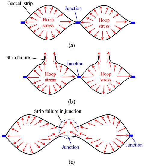
Figure 1.
(a) schematic of hoop stress offered by geocell strip and junction; (b) schematic of strip failure; (c) schematic of strip failure in junction.
Bai [18] investigated the mechanical response of three kinds of geocell strips made from high-density polyethylene (HDPE), polypropylene (PP), and polyester (PET) at low temperatures through the use of uniaxial tensile tests. It was observed that HDPE and PET geocell strips were more sensitive to temperature, while PP geocell strips were less sensitive to temperature. Li [19] explored the effects of the tensile rate on the stress–strain relationship and the peak tensile strength of HDPE geocell strips by tensile tests and proposed a mathematical prediction model of stress–strain. Liu [20] studied the failure mechanisms of a geocell wall and junctions subjected to various loading conditions. Zhao [21] developed a polymer-blend geocell (PBG) and studied the yield strength, tensile strength, and elongation at the break of the PBG.
Both pieces of the literature above studied the mechanical properties of geocell strips through the use of tensile tests. It should be noted that Bai [18] and Li [19] used rectangular specimens, while Liu [20] and Zhao [21] used dumbbell specimens during the tensile test. The type I dumbbell specimen was recommended in the Standard Test Method for Tensile Properties of Plastics (ASTM D638-2014) [22], as shown in Figure 2a. The type II rectangular specimen was recommended in the Plastics-Determination of tensile properties (GB/T 1040–2006) [23], as shown in Figure 2b. At present, the influence of dumbbell and rectangular specimens on the tensile test results lacks detailed investigation.
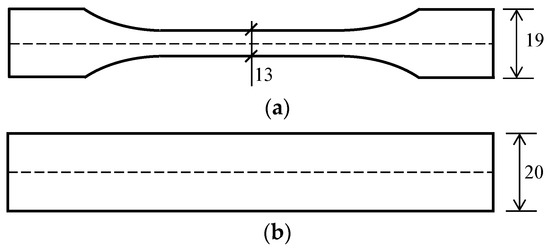
Figure 2.
(a) type I dumbbell specimen; (b) type II rectangular specimen (unit: mm).
The two adjacent geocell strips were welded to form the junction, and the geocell strips at the junction, due to the influence of the ultrasonic welding process, would inevitably be damaged. If the strip at the junction failed, the hoop effect of the geocell would also be reduced, as shown in Figure 1c. However, the influence of the junction on the tensile mechanical properties of the geocell strips was not considered in the current study. The test results of the strip with and without a junction also lacked comparison. Yang [24] studied the failure mechanisms of junctions under different clamping distances but did not consider the influence of the junction on the geocell strip.
In addition to axial force, the geocell strips were generally subjected to the combination of axial force and moment in the slope shoulder, as shown in Figure 3. If the geocell strip failed in the slope shoulder, the reinforced effect would be reduced, and the sliding resistance at the slope would also be reduced. Hence, the mechanical behavior of the geocell strips at the slope shoulder also played a crucial role in the stability of the reinforced soil structure. However, there is a lack of investigations concerning the tensile mechanical behavior of geocell strips subjected to a combination of axial force and moment. Additionally, there is also a lack of comparison concerning the difference in the test results between tensile tests and trapezoidal tests.
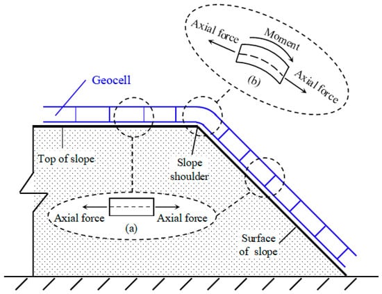
Figure 3.
(a) strip subjected to axial force; (b) strip subjected to the combination of axial force and moment.
Based on the above analysis, this study performed a series of laboratory tests on HDPE geocell strips using a universal testing machine to further investigate the tensile mechanical behavior of HDPE geocell strips. Tensile tests were performed to investigate the effects of specimen shape, specimen width, and the junction on the tensile strength and elongation of the geocell strips. Trapezoidal tests were carried out to explore the test results of the geocell strip subjected to a combination of tension and moment. The results of the tensile tests and trapezoidal tests on the geocell strip were also compared. The experimental results of this paper can provide a reference for the design of geocell-reinforced soil structures.
2. Materials and Methods
2.1. Test Equipment and Materials
In this paper, the laboratory’s universal tensile testing machine for geosynthetic materials was used to study the tensile mechanical behavior of geocell strips, as shown in Figure 4. The specifications of the universal testing machine for geosynthetics are presented in Table 1. It should be noted that the clamp used in relation to the test equipment played a critical role in the reliability of the test results. The clamping surfaces of the flat compression clamp should be in the same plane. Meanwhile, the principal axis direction of the specimen coincided with the center line direction of the flat compression clamp. In addition, the number of bolts on the clamp should not be less than 3 and should be odd. In the process of tightening the flat compression clamp, the torque should be evenly applied to the bolts on the clamp to avoid stress concentration in relation to the specimen. Hence, a flat compression clamp was used in the experiment to ensure that the effect of the clamp on the test result was excluded. Additionally, polyvinyl chloride (PVC) strips were also used to place in the clamp to increase friction to avoid the specimen sliding or stress concentrations at the clamp.
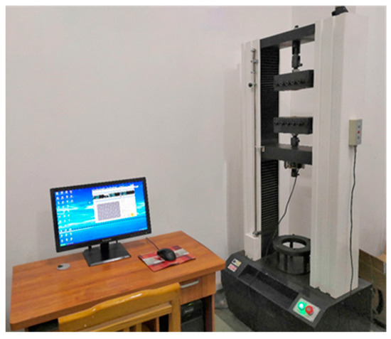
Figure 4.
The universal testing machine for geosynthetics.

Table 1.
The specifications of the universal testing machine for geosynthetics.
Geocell strips made from HDPE were used in this paper. The HDPE geocell strips are integrated using ultrasonic welding to form the welding junction. The specifications of the geocells mainly included the height of the geocell and the spacing of the junction. The height of the geocell was the width of the geocell strip. In this test, the height of the HDPE geocell was 50 mm, and the spacing of the junction was 400 mm.
2.2. Experimental Program
2.2.1. Tensile Test for Strip
The schematic of the geocell made of strip and junction is shown in Figure 5a. In order to clearly describe the test program in this study, letters A to F, and M and N, were used to represent the corresponding geocell strip. According to Figure 2, the type I dumbbell specimen and the type II rectangular specimen were prepared as HDPE geocell strips, as shown in Figure 3b. To ensure the reliability of the tensile test, the number of each specimen shall not be less than five. Meanwhile, the tensile rate was 50 mm/min. A comparison of the type I dumbbell specimen and type II rectangular specimen was performed to investigate the effect of specimen shape on the tensile mechanical properties of the HDPE geocell strips.
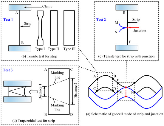
Figure 5.
Schematic of geocell and experimental program: (a) schematic of geocell; (b) tensile test for strip; (c) tensile test for strip with junction; (d) trapezoidal test for strip (letters A to F, and M and N, were used to represent the corresponding geocell strip).
Due to the difference in the width between the type I dumbbell specimen and the type II rectangular specimen, the influence of the specimen width on the tensile mechanical behavior of the geocell strip was also investigated in this paper. According to the Test Methods of Geosynthetics for Highway Engineering (JTG E50-2006) [25], the width of the specimen used in the tensile test was 50 mm. Fortunately, the width of the geocell strip used in this paper was also 50 mm. Hence, a specimen with a width of 50 mm can be directly obtained by cutting the geocell strip used in this paper. In order to distinguish the specimen with a 50 mm width from the type II rectangular specimen, the rectangular specimen with a width of 50 mm was named the type III rectangular specimen. It should be noted that the parameters of the type III rectangular specimen were the same, except that the specimen width was different from that of the type II rectangular specimen to reduce the influence of other factors on the results. A comparison of the type II rectangular specimen and type III rectangular specimen was performed to investigate the effect of specimen width on the tensile mechanical characteristics of the HDPE geocell strips.
2.2.2. Tensile Test for Strip with Junction
The corresponding letters of the strip specimens with junctions were E, F, M, and N, as shown in Figure 5a. The junction was located in the middle of the geocell strip. The experimental program of the tensile test for geocell strips with the junction is shown in Figure 5b. Since there is no specification for the tensile test of the strip with a junction, the size of the strip specimen with a junction was referred to the Geotextiles and geotextile-related products—Strength of internal structural junctions—Part 1: Geocells (ISO 13426-2019) [26]. By comparing the tensile strength and elongation of the geocell strips with and without a welding junction, the influence of the junction on the tensile mechanical properties of the geocell strip was studied. It is worth mentioning that the test result of the HDPE geocell strips without the welding junction was that of a type III rectangular specimen.
2.2.3. Trapezoidal Test for Strip
The geocell strips subjected to the combination of tension and moment were simulated by Liu [20] using trapezoidal tests. This paper referred to Liu’s experimental ideas. The trapezoidal specimen is shown in Figure 5d. Since there is no specification for the trapezoidal test of the geocell strip, the size of the geocell strip specimen referred to the Standard Test Method for Trapezoid Tearing Strength of Geotextiles (ASTM D4533-15) [27], which applies to woven or non-woven geotextiles and fabrics. However, the above specification did not mention whether it is applicable to geocells. Hence, in this paper, the dimensions of the trapezoidal specimen obtained from the geocell strip referred to the ideas of Liu [20] to ensure the reliability of the test results. The width of the trapezoidal specimen was the width of the geocell strip, and the length of the specimen was consistent with the size in the specification. The clamping distances of 1 and 2 of the specimen were 50 mm and 100 mm, respectively. The experimental program of the trapezoidal test for the geocell strips is shown in Figure 5d. Additionally, to reduce the influence of the tensile rate on the test results and to facilitate the comparison with the tensile results of the strip, the rate of the trapezoidal test was also taken as 50 mm/min.
3. Results and Discussion
This section presents a summary of the results and analyses of the laboratory tests including tensile test and trapezoidal test conducted on HDPE geocell strips by using the universal testing machine. Firstly, the tensile test results with different specimen shapes and widths were analyzed. Meanwhile, two variables, “strength ratio (Rs)” and “elongation ratio (Re)” were introduced to discuss the effect of the specimen shape and width on the tensile mechanical behavior of the HDPE geocell strips. Then, the failure characteristics and tensile test results of the strip with a junction were studied. Additionally, two variables, “strength retention rate (RRs)” and “deformation retention rate (RRd)”, were also introduced to compare the effect of the welding junction on the tensile strength and elongation of the HDPE geocell strip. Finally, the trapezoidal test results of the HDPE geocell strip were discussed. Two variables, “force ratio (RF)” and “displacement ratio (RD)”, were also introduced to discuss the difference in geocell strips subjected to the tension only and the combination of tension and moment by comparing the results of the tensile test and trapezoidal test.
3.1. Comparison of Different Specimen Shapes and Specimen Widths
Figure 6 presents a plot of the tensile strength versus the elongation specimen for that of the type I dumbbell specimen, type II rectangular specimen, and the type III rectangular specimen of the HDPE geocell strip under axial force. On the whole, the tensile test curves of the three kinds of specimens were similar, as shown in Figure 6, showing obvious yield deformation at first and then fracture after a period of deformation, which was consistent with the typical tensile test curves of the HDPE material.
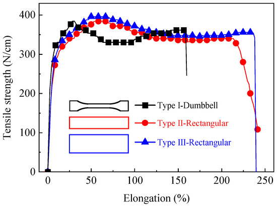
Figure 6.
Tensile results of three kinds of specimens of HDPE geocell strips.
From Figure 6, the failure pattern of the HDPE geocell strips presented with ductile failure, which was consistent with Liu [20]. Compared with the type II and type III rectangular specimens, the type I dumbbell specimen showed obvious secondary growth with increased elongation after the first tensile yield. The type I dumbbell specimen presented the characteristics of obvious strain softening first and then hardening in the tensile process. Meanwhile, the type I dumbbell specimen failed earlier than type II and type III rectangular specimens. The experimental results were related to the geometry of the specimen and the production technology of the HDPE geocell strip, among which the geometry was the main reason.
Generally, the narrow parallel area in the middle of the dumbbell-shaped specimen was called the gauge area, and the arc outside of the gauge area was called the transition area. During the test, the gauge area of the type I dumbbell specimen rapidly reached the yield strength first under axial force, which showed yield in the tensile curve. After the yield point, the strength of the specimen decreased and entered the strain-softening stage. At the same time, as the deformation gradually extended to the transition zone of the specimen, the deformation in the transition zone required greater axial force because the cross-section area of the arc in the transition area is larger and more complex than that of the narrow parallel area in the gauge area. In the corresponding test curve, the specimen showed secondary growth after yielding, showing obvious strain hardening. However, with increased axial force, the tensile strength of the specimen in the gauge area was greater than the allowable strength of the specimen, and the specimen failed.
In addition to the geometry of the specimen, the tensile mechanical behavior of the type I specimen was also related to the production technology used in terms of the HDPE geocell strip. The HDPE geocell strips were generally produced through extrusion. Because there is no directional stretching, the molecular chain of the strip hardly changed; therefore, the strain-softening characteristics of the HDPE strips were first shown in the tensile test. As the crystalline polymer exceeded the yield point, the molecular chains in the amorphous region moved and began to orient along the axial force direction, thus increasing the intermolecular force. At this time, it was necessary to increase the axial force to overcome the intermolecular interaction. However, when the axial force increased, the relative displacement between the molecules also increased, and finally, the molecular chain broke, which was the macroscopic performance of damage. From the above test curves, it can be seen that the specimen had a significant impact on the results of the tensile test.
In descending order, the tensile strength and elongation at yield of the three kinds of specimens were: type III rectangular specimen, type II rectangular specimen, and type I dumbbell specimen. In order to quantitatively analyze the effect of the shape and width of the specimen on the tensile strength and elongation of the HDPE geocell strip, two variables, “strength ratio (Rs)” and “elongation ratio (Re)”, were introduced. “Strength ratio (Rs)” was the ratio of the tensile strength at the yield of the type II rectangular specimen, the type I dumbbell specimen was to that of the type III rectangular specimen. “Elongation ratio (Re)” was the ratio of the elongation at the yield of the type II rectangular specimen, and the type I dumbbell specimen was to that of the type III rectangular specimen. The formulas of “strength ratio (Rs)” and “elongation ratio (Re)” are shown in (1) and (2), respectively.
where the T* is the tensile strength at the yield of the type II rectangular specimen, for the type I dumbbell specimen, N/cm; TIII-rec is the tensile strength at the yield of the type III rectangular specimen, N/cm.
where ε* is the elongation at the yield of the type II rectangular specimen, and for the type I dumbbell specimen, N/cm; is the elongation at the yield of the type III rectangular specimen, N/cm.
Taking into account for errors in the test data, at least five tests were conducted for each type during the laboratory tensile tests. Compared with the tensile strength and elongation of the type I dumbbell specimen, the test results of the type II rectangular specimen of the HDPE geocell strip were closer to the type III rectangular specimen, as shown in Table 2. By comparing the strength ratio (Rs) and elongation ratio (Re) of the three kinds of specimens, it can be seen that the differences in Rs and Re between the type I dumbbell specimen and the type II rectangular specimen were 2% and 38%, respectively, while the differences in Rs and Re between the type II rectangular specimen and the type III rectangular specimen were only 5% and 1%, respectively.

Table 2.
Tensile test results of three kinds of specimens of HDPE geocell strips.
It was determined that specimen shape had a significant effect on the elongation of the HDPE geocell strip, and the difference between the elongation at the yield of the type I dumbbell specimen and the type II rectangular specimen was as high as 38%. The reason was that the cross-sectional area of the transition zone of the type I dumbbell specimen was larger than the cross-sectional area of the gauge area, and the transition zone continued to deform after the gauge zone yielded during the test, which accelerated the fracture of the type I dumbbell specimen in the gauge zone, thus reducing the elongation of the type I dumbbell specimen. Compared with the elongation at yield, the influence of specimen shape on the strength of the type II rectangular specimen and type I dumbbell specimen was almost insignificant, and the difference between them was only 2%. Therefore, it can be seen that the tensile strength of the type I dumbbell specimen was similar to that of the type II rectangular specimen.
Compared with specimen shape, specimen width had little effect on the tensile strength and elongation of the HDPE geocell strips, which were all less than 5%. Previous studies have shown that the elongation of geocell strips in reinforced soil structures was generally less than 25%; therefore, it is necessary to pay attention to the strength of geocell strips. Based on the above analysis, it can be seen that the shape and width of the specimen had little influence on the strength of the HDPE geocell strip. Thus, the type III rectangular specimen can be selected for tensile test specimens, especially in the field, to improve test efficiency.
The test results showed that with the increase in specimen width, the tensile strength and elongation of the specimen had almost no change. The width ratio of the type II rectangular specimen and the type III rectangular specimen was 1:2.5, but the Rs and Re of the two specimens were 1:1.05 and 1:1.01, respectively. The reason was that HDPE is a tough material with low stress sensitivity. The specimen width had little effect on the tensile strength and elongation. The tensile strength and elongation of the type II rectangular specimen were in good agreement with that of the type III rectangular specimen.
In addition to tensile strength and elongation, the tensile modulus is also an important mechanical parameter in engineering design and improving our understanding of the material. In general, the tensile modulus of the material included the initial tensile modulus, secant tensile modulus, and tangent tensile modulus. Previous studies have shown that when the stress–strain relationship of the material was linear in the initial stage, the initial tensile modulus can be used. However, when the stress–strain relationship presented a nonlinear trend, a secant tensile modulus should be adopted. According to the above test results, the tensile test curves of the three kinds of specimens showed a nonlinear trend during the test; therefore, the secant tensile modulus was used to analyze the tensile results of the three specimens.
The plot of the tensile modulus versus the elongation of the three types of specimens is shown in Figure 7. It was observed that the curve of the three types of specimens showed similar characteristics. The tensile modulus of the three types of specimens decreased with the increase in elongation, especially in the range of 0–20%, as shown in Figure 7. With the elongation reaching 100%, the change in the tensile modulus was very small until the end of the test. In addition, the tensile modulus curves of the three types of specimens tend to coincide gradually with the increase in elongation.
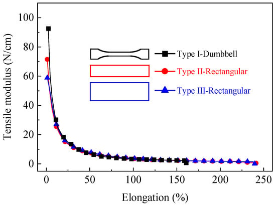
Figure 7.
Tensile modulus vs. elongation of three kinds of specimens.
In the initial stage of the test, the tensile modulus of the three types of specimens from large to small were as follows: type I dumbbell specimen, type II rectangular specimen, and type III rectangular specimen. The tensile modulus of the type I dumbbell specimen was about 1.30 times that of the type II rectangular specimen, and that of type II rectangular specimen was about 1.21 times that of the type III rectangular specimen. It was observed that the influence of the specimen shape on the tensile modulus of the HDPE geocell strip was greater than the specimen width, which was about 1.16 times the specimen width. Additionally, the influence of the specimen shape on the elongation of the HDPE geocell strip was also greater than the specimen width. The plot of the nonlinear fitting results regarding the tensile modulus of the three types of HDPE specimens is shown in Figure 8.
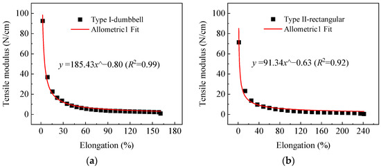
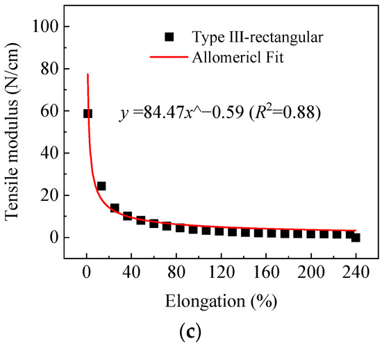
Figure 8.
Nonlinear fitting results of three kinds of specimens: (a) type I dumbbell specimen; (b) type II rectangular specimen; (c) type III rectangular specimen.
From Figure 8a–c, it can be seen that the nonlinear fitting results of the three types of specimens showed good agreement with the experimental data, and the fitting correlation coefficients were all above 0.88. Among them, the fitting correlation coefficient of the type I dumbbell specimen was higher than that of the type II rectangular specimen and the type III rectangular specimen, which was 0.99. The fitting correlation coefficients of the type II rectangular specimen and the type III rectangular specimen were 0.92 and 0.88, respectively.
3.2. Test Results of Strip with Junction under Axial Force
Figure 9 shows the tensile specimen of the HDPE geocell strip with a welding junction and the failure characteristics of the tensile specimen after the tensile test. From Figure 9, the following experimental phenomena were observed. Firstly, the strip elongated under the axial force. Then, the strip presented the characteristics of an obvious necking phenomenon. Lastly, the failure occurred at the welding junction.
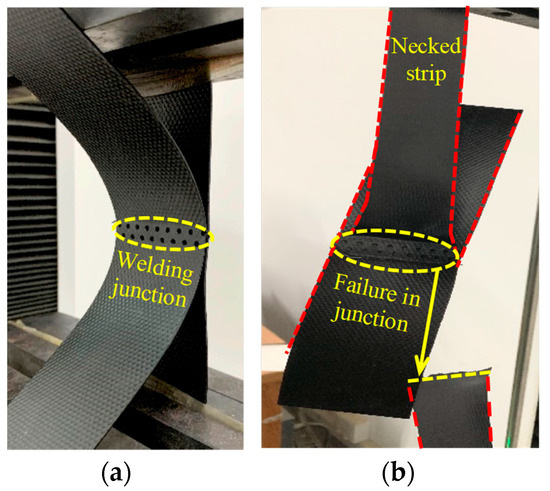
Figure 9.
Tensile specimen and failure characteristic: (a) strip with junction before test; (b) strip with junction after test.
In order to better reflect the test characteristics during the test, the failure process of an HDPE geocell strip with a welding junction was analyzed, as shown in Figure 10.
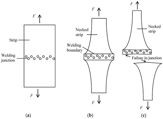
Figure 10.
Analysis of failure process of HDPE geocell strips with junction in test: (a) before test; (b) test in progress; (c) end of test.
From Figure 9 and Figure 10, the failure pattern of HDPE geocell strips with a junction was similar to the results obtained by Yang [22]. In fact, the boundary of the welding junction was not clear before the tensile test, as shown in Figure 10a. During the tensile test, the boundary of the welding junction gradually became clear, and the strip showed obvious necking deformation, as shown in Figure 10b. Lastly, the failure occurred at the boundary of the welding junction, as shown in Figure 10c. It should be noted that the area of the welding junction was reduced when the specimen failed. Meanwhile, the boundary of the welding junction changed from a straight line to a curve. Combined with the experimental phenomena and an analysis of the failure process, it can be known that the welding junction was the weak point of the specimen used in this study, especially the edge between the junction and the strip.
In order to analyze the effect of the junction on the tensile strength and the elongation of the HDPE geocell strip, the test results of the HDPE geocell strip with and without a junction were compared. The plot of the tensile strength versus the elongation of the HDPE geocell strip with and without a junction is shown in Figure 11. It is worth mentioning that the test results of the HDPE geocell strip without a welding junction were the result of the type III rectangular specimen in Section 3.1.
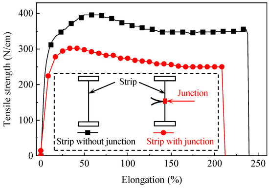
Figure 11.
Results of HDPE geocell strip without and with welding junction.
From Figure 11, the tensile mechanical behavior of the HDPE geocell strips with and without a welding junction under axial force showed similarities and differences. The main similarity was the trend of the two test curves. At first, two test curves showed obvious yield characteristics and then gradually tended to be stable until failure. Hence, the tensile results of the HDPE geocell strip with a welding junction showed good property inheritance compared with the results of the HDPE geocell strip without a junction. The difference was the tensile strength of the HDPE geocell strip without a welding junction grew faster than that of the strip with a junction. Additionally, the HDPE geocell strips with a junction showed plastic yield earlier than that of the strip without a junction. It is worth mentioning that although the two adjacent geocell strips were connected at the geocell junction, the tensile strength and elongation of the tensile results were not increased compared with that of a single strip.
In order to quantitatively evaluate the effect of a welding junction on the tensile strength and elongation of an HDPE geocell strip, two variables, “strength retention rate (RRs)” and “deformation retention rate (RRd)”, were introduced. The “strength retention rate (RRs)” was the ratio of the tensile strength of an HDPE geocell strip with a welding junction to that of an HDPE geocell strip without a welding junction. The “strength retention rate (RRs)” represented the impact of the junction on the tensile strength of the strip. The greater the strength retention rate, the better the strength of the strip with a junction was maintained, showing that the junction had less influence on the strip and vice versa. The “deformation retention rate (RRd)” was the ratio of the elongation of an HDPE geocell strip with a welding junction to that of an HDPE geocell strip without a welding junction. The “deformation retention rate (RRd)” represented the effect of the junction on the elongation of the strip. The greater the deformation retention rate, the better the deformation of the strip with a junction was maintained, showing that the junction had less influence on the strip, and vice versa. The formulas of “strength retention rate (RRs)” and “deformation retention rate (RRd)” are shown in (3) and (4), respectively.
where and were the tensile strength of the HDPE geocell strips with and without a welding junction, N/cm.
where and were the elongation of the HDPE geocell strips with and without a welding junction, %.
The “strength retention rate (RRs)” and “deformation retention rate (RRd)” of the HDPE geocell strips with a welding junction used in this study were 76.3% and 81.12%, respectively. According to the results, it was observed that the welding junction reduced the tensile strength and elongation of the HDPE geocell strips; therefore, the impact of the junction on the tensile mechanical behavior of the geocell strip cannot be ignored. However, although the welding junction caused damage to the HDPE geocell strip, the strength and deformation performance of the strip was still maintained at more than 75%. Based on the test results, it can be seen that the welding junction had little influence on the performance of the HDPE geocell strips. An RRd greater than the RRs meant that the influence of the welding junction on deformation performance was lower than that of the welding junction on strength performance.
In addition to paying attention to the influence of the junction on the strength and deformation of the strip, the deformation coordination performance of the strip with a junction should also be considered. The deformation coordination performance reflected whether the strength and deformation of the strip with a junction were fully exerted when the strip with a junction failed. In this paper, the deformation coordination performance of the specimen used in this study could be obtained from the difference between RRs and RRd. Fortunately, the difference between RRs and RRd was only 4.82%, showing that the HDPE geocell strip with a welding junction used in this paper had good coordination performance. Based on the test results, it is suggested that the influence of the junction on the tensile mechanical behavior of the strip should be added to the evaluation index for the geocell to comprehensively analyze the performance of the geocell to ensure the safety and reliability of the reinforced soil structure.
3.3. Trapezoidal Test Results of HDPE Geocell Strip
The plot of the trapezoidal test results of the HDPE geocell strips is shown in Figure 12. It should be noted that the trapezoidal test results cannot be expressed through tensile strength (N/cm) and elongation (%). Due to the fact that the specimen used in the test is trapezoidal and the two sides of the specimen have different lengths after installation, the tensile strength cannot be calculated from the trapezoidal test results. Therefore, the results of the trapezoidal test were expressed as force (kN) versus displacement (mm).
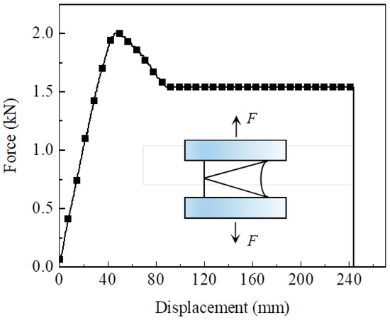
Figure 12.
Trapezoidal test results of HDPE geocell strip.
From Figure 12, it can be seen that the curve of the trapezoidal test of the HDPE geocell strip was similar to that of the tensile test, showing the characteristics of obvious yield first and then significant plastic deformation before failure. The reason was that the stress of the trapezoidal specimen would be redistributed during the test due to the plastic flow effect, and then the trapezoidal specimen would gradually switch to the typical tensile test. Hence, the HDPE geocell strip showed progressive failure in the tensile test and trapezoidal test. Meanwhile, the trapezoidal specimen inherited the excellent behavior of HDPE.
In this paper, the tensile test was used to simulate the axial force on the geocell strip, and the trapezoidal test was used to simulate the combination of tension and moment on the geocell strip. Hence, to investigate the effect of the loading conditions on the test force and displacement of the HDPE geocell strip, the results of the tensile test and trapezoidal test were compared, and two variables, “force ratio (RF)” and “displacement ratio (RD)”, were introduced. “Force ratio (RF)” was the ratio of the force of HDPE geocell strip subjected to the combination of tension and moment to that of HDPE geocell strip subjected to tension only. “Displacement ratio (RD)” was the ratio of the displacement of the HDPE geocell strip subjected to the combination of tension and moment to that of an HDPE geocell strip subjected to tension only. The formulas of “force ratio (RF)” and “displacement ratio (RD)” are shown in (5) and (6), respectively.
where was the force of an HDPE geocell strip subjected to a combination of tension and moment, N; was the force of an HDPE geocell strip subjected to tension only, N.
where was the displacement of an HDPE geocell strip subjected to a combination of tension and moment, mm; was the displacement of an HDPE geocell strip subjected to tension only, mm.
The force ratio (RF) and the displacement ratio obtained from the results of the tensile test and trapezoidal test were 0.87 and 1.51, respectively. The results showed that the force obtained from the trapezoidal test was less than that of the tensile test. It was concluded that the test force of the geocell strip subjected to the combination of tension and moment was less than that of the geocell strip subjected to tension only. Although the strength of the strip subjected to the combination of tension and moment was reduced, the reduction range was within 15%. Different from the test force, the failure displacement of the trapezoidal test was grater than that of the tensile test. The reason was that the strip subjected to the tension only rapidly yielded and turned into plastic elongation. However, the strip subjected to the combination of tension and moment would be redistributed at first during the test due to the plastic flow effect, and then the trapezoidal specimen would gradually switch to the typical tensile test for the strip. The HDPE geocell strip showed an obvious progressive failure in the trapezoidal test. Hence, the failure displacement of the geocell strip subjected to the combination of tension and moment was greater than that of the geocell strip subjected to the tension only. Based on the above analysis, the strength of the geocell strip used in the slope shoulder, as shown in Figure 3b, would be reduced, but the deformation would be increased. It is necessary to strengthen monitoring of the geocell strip in the slope shoulder to ensure the safety of the structure.
4. Conclusions
This paper described a series of tensile tests that were performed to explore the effects of several factors, including specimen shape, specimen width, and welding junction, on the tensile mechanical behavior of HDPE geocell strips. Meanwhile, the tensile characteristics of the geocell strip subjected to a combination of tension and moment were obtained by conducting trapezoidal tests. Additionally, the results of the trapezoidal test and tensile test were also compared. The following conclusions were obtained.
(1) Compared with the type II and type III rectangular specimens, the test curves of the type I dumbbell specimen presented the characteristics of obvious secondary growth and rapid fracture due to the complexity of the cross-section area of the transition area of the dumbbell specimen.
(2) The specimen shape and width had little effect on the tensile strength of the HDPE geocell strip, within 5%. However, the specimen shape had a great effect on the elongation, and the difference of Re between the type I dumbbell and type II rectangular was up to 38%. Additionally, the impact of specimen shape on the tensile modulus of the strip was greater than that of the specimen width, which was about 1.16 times.
(3) The HDPE geocell strip with a welding junction under axial force presented ductile failure and failed at the junction. Based on the test results, the effect of welding junction on the tensile mechanical behavior of HDPE geocell strip cannot be ignored because the RRs and RRd of the junction to the strips were 76.3% and 81.12%, respectively.
(4) The test curve of the trapezoidal test was similar to that of the tensile test because the stress of the HDPE trapezoidal specimen with a plastic flow effect would be redistributed. However, the force of trapezoidal test was 0.87 times that of the tensile test, indicating that the capacity against the failure of the strip was reduced under the combination of tension and moment.
In this paper, the HDPE geocell strip was used in the test. In addition to HDPE, polypropylene (PP) and polyester (PET) are also commonly used to make geocell strips. The follow-up work will investigate the effect and difference of three types of material on the tensile mechanical behavior.
Author Contributions
Writing—original draft preparation, Z.Z.; writing—review and editing, X.H. and H.L.; validation, W.W., G.Y. and Y.L.; funding acquisition, G.Y.; Methodology, Z.Z., G.Y. and Y.L. All authors have read and agreed to the published version of the manuscript.
Funding
This research was supported by the National Natural Science Foundation of China (NSFC) (Grant No. 52079078).
Institutional Review Board Statement
Not applicable.
Informed Consent Statement
Not applicable.
Data Availability Statement
The data used to support the findings of this study are available from the corresponding author upon request.
Conflicts of Interest
The authors declare no conflict of interest.
References
- Campos, P.C.d.O.; Paz, T.d.S.R.; Lenz, L.; Qiu, Y.; Alves, C.N.; Simoni, A.P.R.; Amorim, J.C.C.; Lima, G.B.A.; Rangel, M.P.; Paz, I. Multi-criteria decision method for sustainable watercourse management in urban areas. Sustainability 2020, 12, 6493. [Google Scholar] [CrossRef]
- Markiewicz, A.; Koda, E.; Kawalec, J. Geosynthetics for Filtration and Stabilisation: A Review. Polymers 2022, 14, 5492. [Google Scholar] [CrossRef] [PubMed]
- Changizi, F.; Razmkhah, A.; Ghasemzadeh, H.; Amelsakhi, M. Behavior of geocell-reinforced soil abutment wall: A physical modeling. J. Mater. Civil. Eng. 2022, 34, 04021495. [Google Scholar] [CrossRef]
- Gedela, R.; Kalla, S.; Sudarsanan, N.; Karpurapu, R. Assessment of load distribution mechanism in geocell reinforced foundation beds using Digital Imaging Correlation Techniques. Transp. Geotech. 2021, 31, 100664. [Google Scholar] [CrossRef]
- Li, L.H.; Sheng, H.Z.; Xiao, H.L.; Zhou, X.L.; Li, W.T.; Liu, Y.M. Mechanical behavior of reinforced embankment with different recycling waste fillers. Ksce. J. Civ. Eng. 2022, 26, 3251–3264. [Google Scholar] [CrossRef]
- Liu, Y.; Deng, A.; Jaksa, M. Three-dimensional modeling of geocell-reinforced straight and curved ballast embankments. Comput. Geotech. 2018, 102, 53–65. [Google Scholar] [CrossRef]
- Gao, A.; Zhang, M. Performance and application of geocell reinforced sand embankment under static and cyclic loading. Coatings 2022, 12, 767. [Google Scholar] [CrossRef]
- Song, G.; Song, X.; He, S.; Kong, D.; Zhang, S. Soil reinforcement with geocells and vegetation for ecological mitigation of shallow slope failure. Sustainability 2022, 14, 11911. [Google Scholar] [CrossRef]
- Kazemi, K.; Arvin, M.R.; Hataf, N.; Khademhosseini, A.; Dehkordi, P.F.; Ghazavi, M.; Ganjian, N.; Karim, U.F.A.; Dash, S.K.; Sireesh, S.; et al. Model studies of square footings on geocell-reinforced slopes. Geosynth. Int. 2022, 29, 576–592. [Google Scholar] [CrossRef]
- Wu, M.; Tian, W.; Liu, F.C.; Yang, J. Dynamic behavior of geocell-reinforced rubber sand mixtures under cyclic simple shear loading. Soil. Dyn. Earthq. Eng. 2023, 164, 107595. [Google Scholar] [CrossRef]
- LI, W.; HAN, S.; HAN, X.; Yao, Y.Y. Experimental and numerical analysis of mechanical properties of geocell reinforced reclaimed construction waste composite base layer. Constr. Build. Mater. 2021, 304, 124587. [Google Scholar] [CrossRef]
- Khan, M.; Puppala, A. Sustainable pavement with geocell reinforced reclaimed-asphalt-pavement (RAP) base layer. J. Clean. Prod. 2023, 387, 135802. [Google Scholar] [CrossRef]
- Wang, X.R.; Zhang, X.D.; Zhu, Y.S.; Li, X.W. Fatigue damage characteristics of geocell-reinforced asphalt mixture. Constr. Build. Mater. 2021, 269, 121252. [Google Scholar]
- Gao, B.; Liu, X.; Liu, J.; Song, L.; Shi, Y.; Yang, Y. Field characterization of dynamic response of geocell-reinforced aeolian sand subgrade under live traffic. Appl. Sci. 2023, 13, 864. [Google Scholar] [CrossRef]
- Garcia, R.S.; Neto, J.O. Stress-dependent method for calculating the modulus improvement factor in geocell-reinforced soil layers. Geotext. Geomembr. 2021, 49, 146–158. [Google Scholar] [CrossRef]
- Gedela, R.; Karpurapu, R. Influence of pocket shape on numerical response of geocell reinforced foundation systems. Geosynth. Int. 2021, 28, 327–337. [Google Scholar] [CrossRef]
- Ardakani, A.; Namaei, A. Numerical investigation of geocell reinforced slopes behavior by considering geocell geometry effect. Geomech. Eng. 2021, 24, 589–597. [Google Scholar]
- Bai, Q.; He, G.; Wang, Y.; Liu, J. Experimental investigation on mechanical properties of geocell strips at low temperature. Materials 2022, 15, 5456. [Google Scholar] [CrossRef]
- Li, J.; Huang, H. Strain rate dependent tensile behavior of hdpe geocell strip. J. Build. Mater. 2008, 11, 47–51. [Google Scholar]
- Liu, Y.; Deng, A.; Jaksa, M. Failure mechanisms of geocell walls and junctions. Geotext. Geomembr. 2019, 47, 104–120. [Google Scholar] [CrossRef]
- Zhao, Y.; Lu, Z.; Yao, H.; Zhang, J.; Yuan, X.Z.; Cui, Y.Y.; Nie, Y.P. Development and mechanical properties of HDPE/PA6 blends: Polymer-blend geocells. Geotext. Geomembranes 2021, 49, 1600–1612. [Google Scholar] [CrossRef]
- ASTM D638-2014; Standard Test Method for Tensile Properties of Plastics. ASTM: Philadelphia, PA, USA, 2014.
- GB/T 1040; Plastics-Determination of Tensile Properties. China, GB: Beijing, China, 2006.
- Yang, G.; Su, P.; Xu, P.; Wang, Z.; Wang, H.; Zuo, Z. Experimental investigation on failure mechanisms of hdpe welded geocell junctions under different Clamping Distances. Appl. Sci. 2022, 12, 5343. [Google Scholar] [CrossRef]
- JTG E50; Test Methods of Geosynthetics for Highway Engineering. JTG: Beijing, China, 2006.
- ISO 13426; Geotextiles and Geotextile-Related Products—Strength of Internal Structural Junctions—Part 1: Geocells. ISO: Geneva, Switzerland, 2019.
- ASTM D4533; Standard Test Method for Trapezoid Tearing Strength of Geotextiles. ASTM: Philadelphia, PA, USA, 2015.
Disclaimer/Publisher’s Note: The statements, opinions and data contained in all publications are solely those of the individual author(s) and contributor(s) and not of MDPI and/or the editor(s). MDPI and/or the editor(s) disclaim responsibility for any injury to people or property resulting from any ideas, methods, instructions or products referred to in the content. |
© 2023 by the authors. Licensee MDPI, Basel, Switzerland. This article is an open access article distributed under the terms and conditions of the Creative Commons Attribution (CC BY) license (https://creativecommons.org/licenses/by/4.0/).