

Experimentally Identifying the Influences of Key Parameters for an Organic Rankine Cycle Using R123

 , ,
, ,
Abstract
1. Introduction
2. Experiments
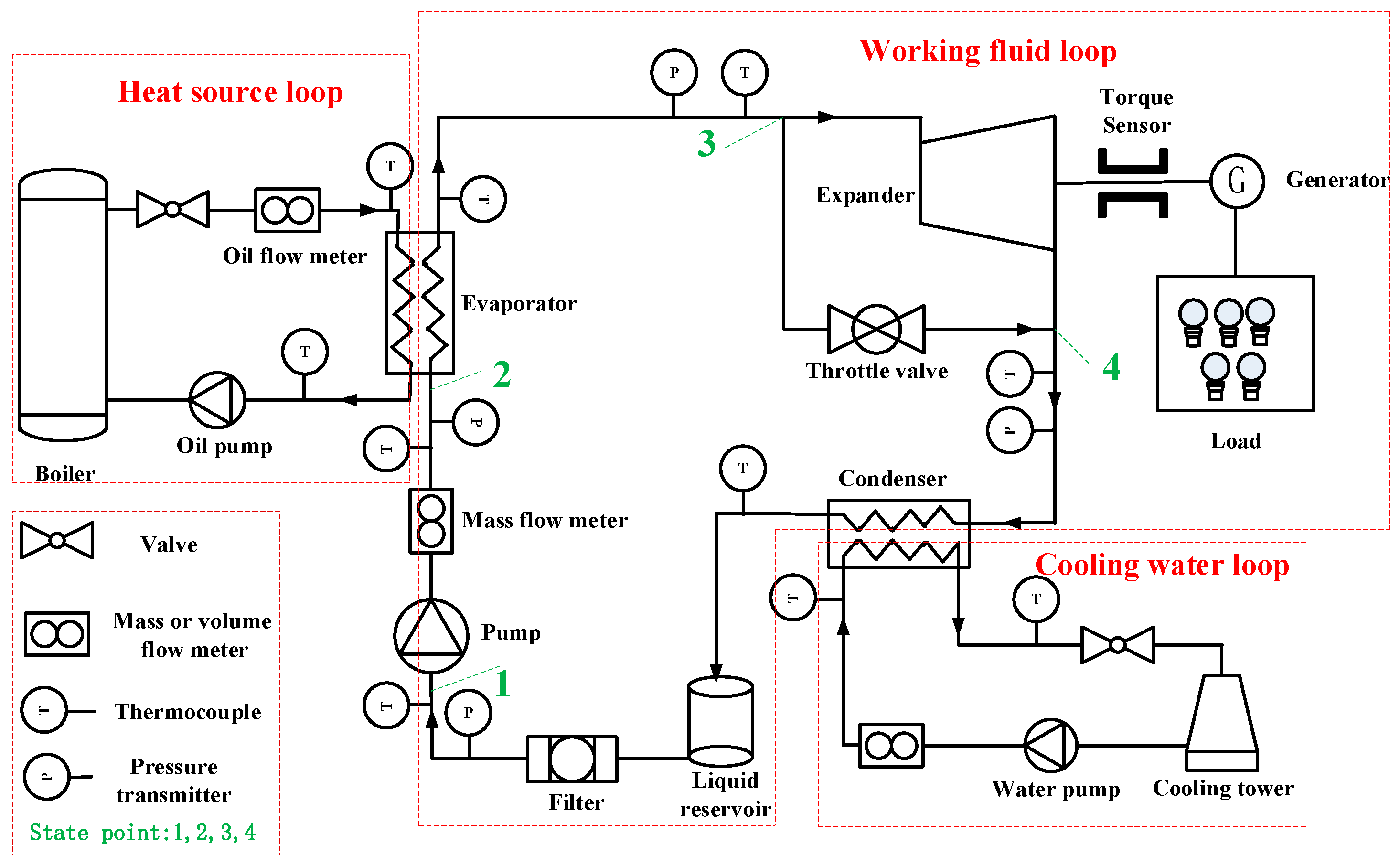
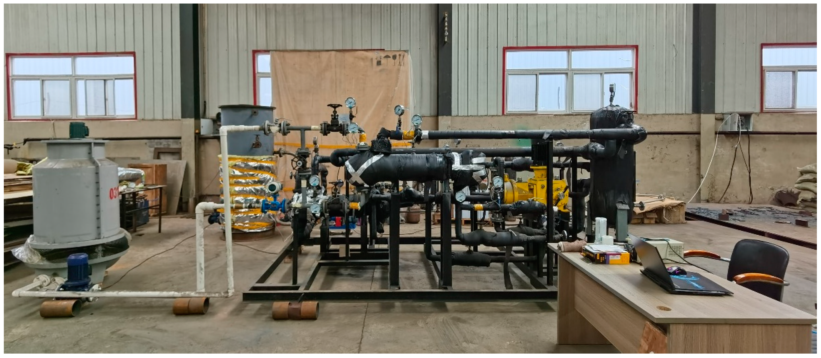
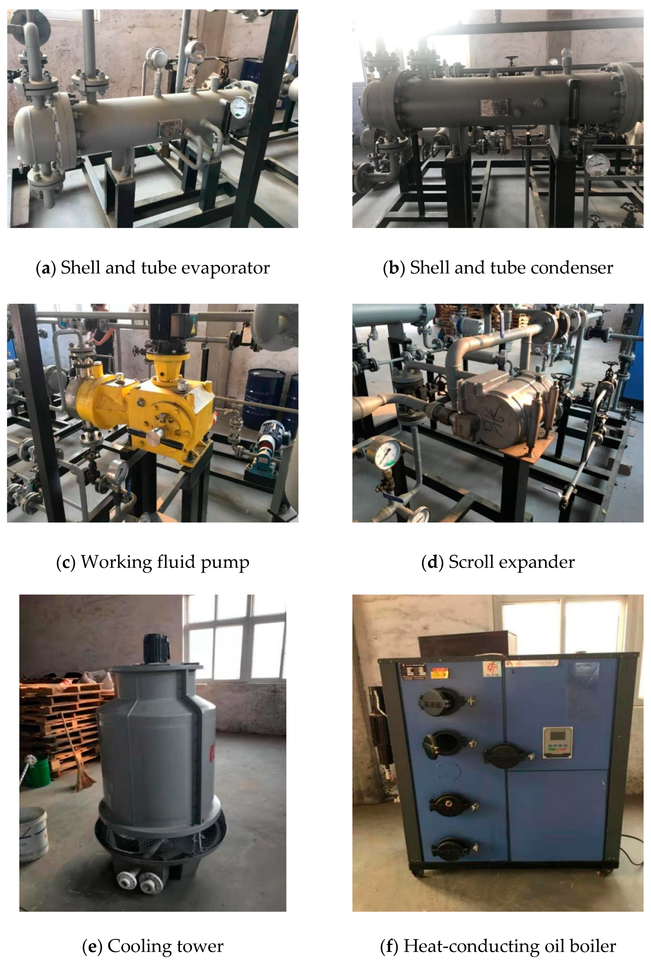
2.1. Test facility
2.2. Measurements
2.3. Test Conditions and Data Reduction
2.4. Uncertainty Analysis
3. Experimental Results and Discussion
3.1. Performance Analysis under the Design Conditions
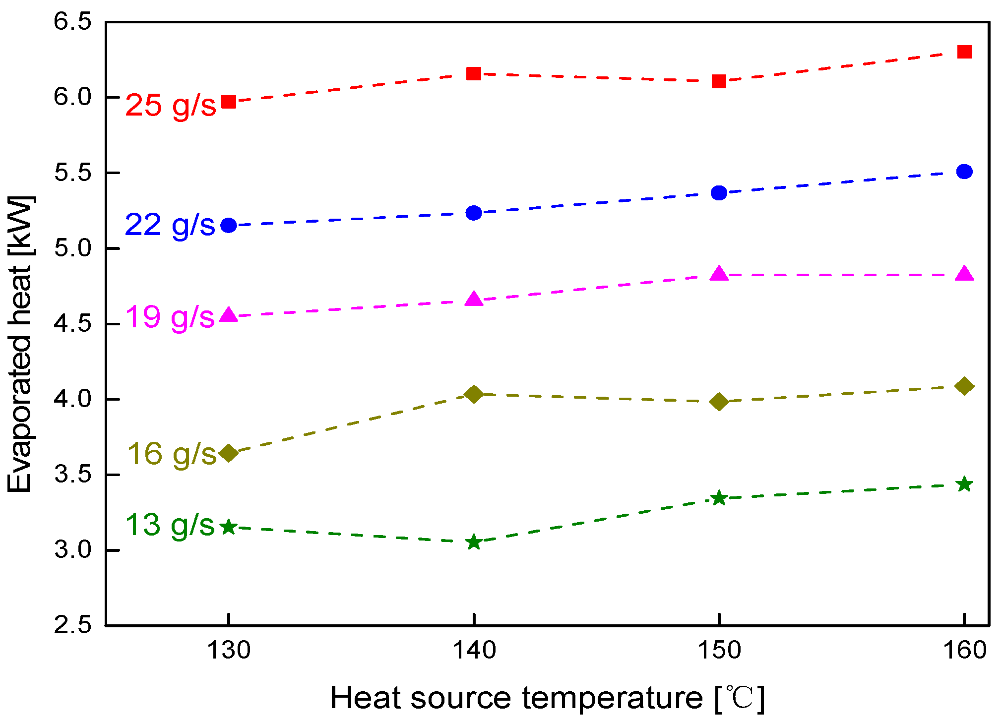
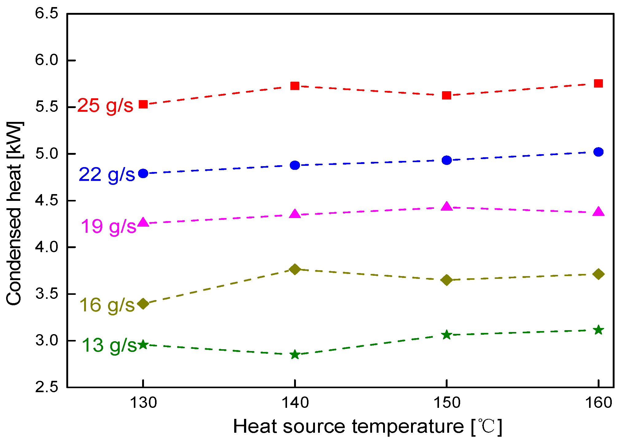
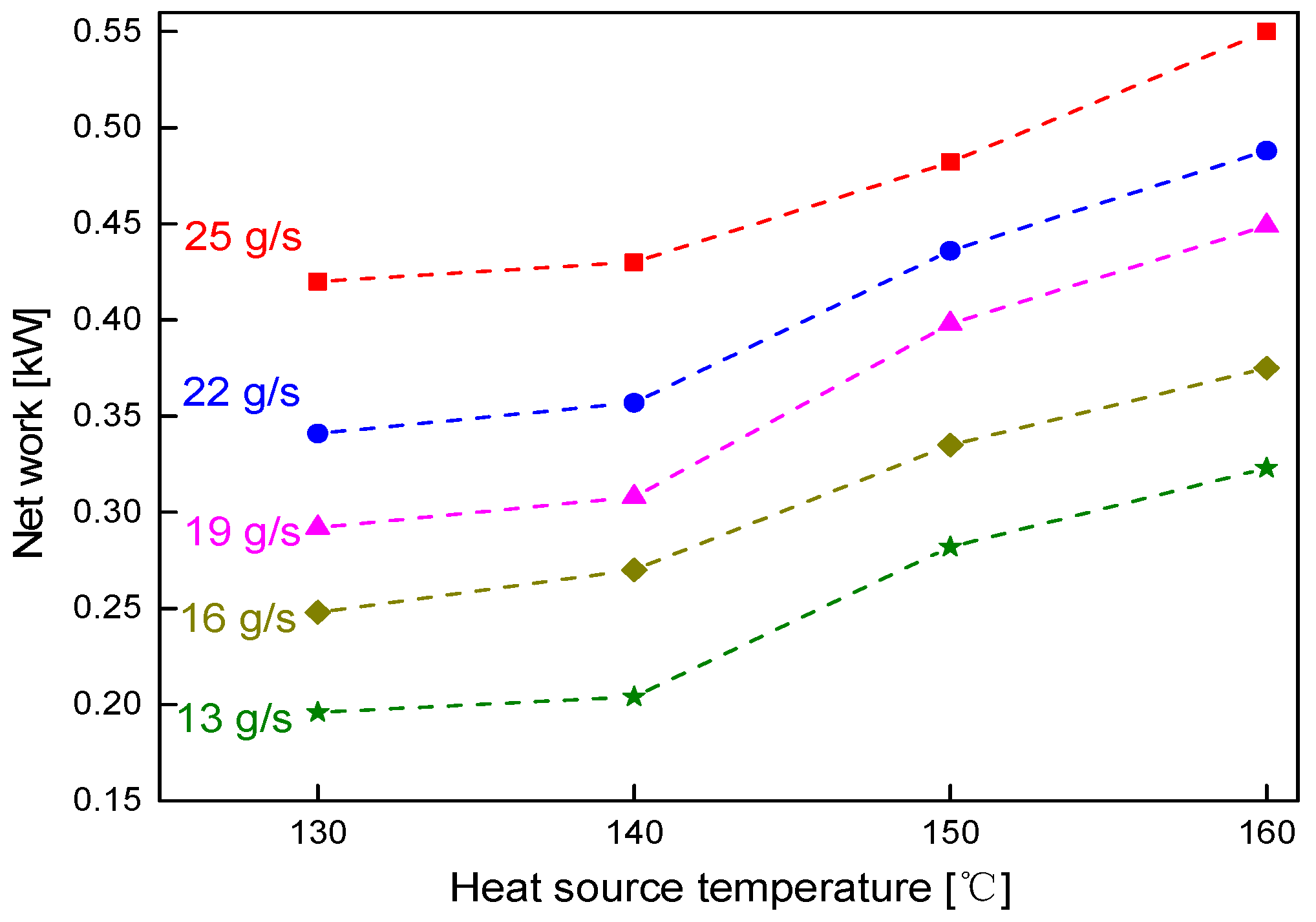
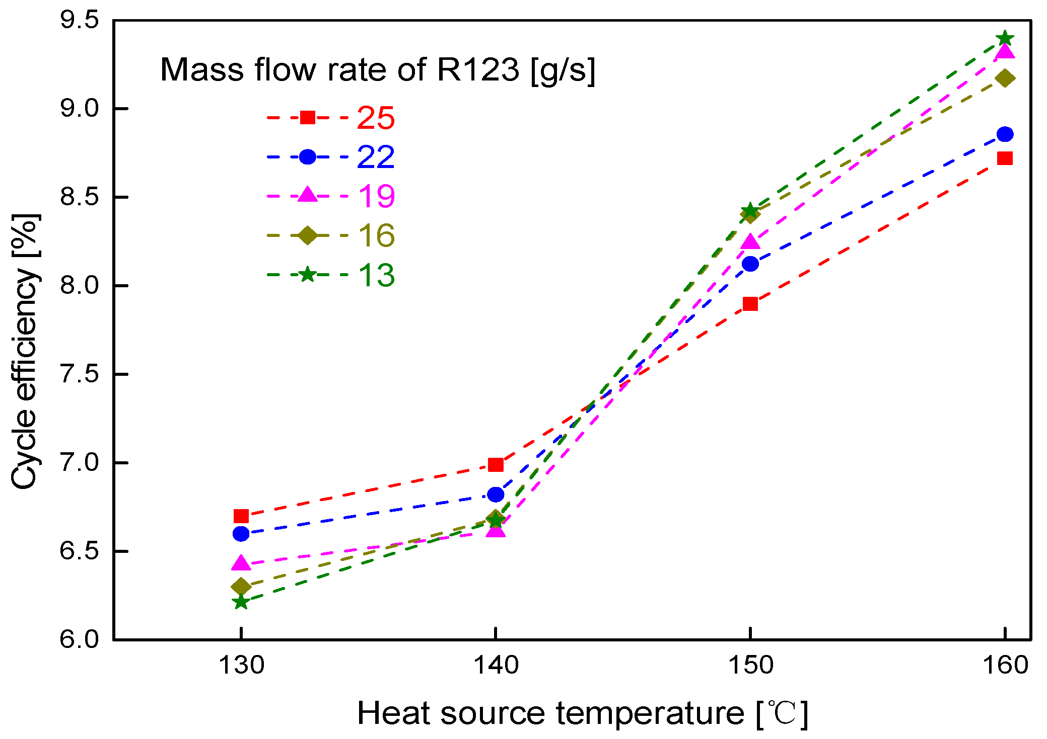
3.2. Effects of Heat Source Temperature and Working Fluid Mass Flow Rate
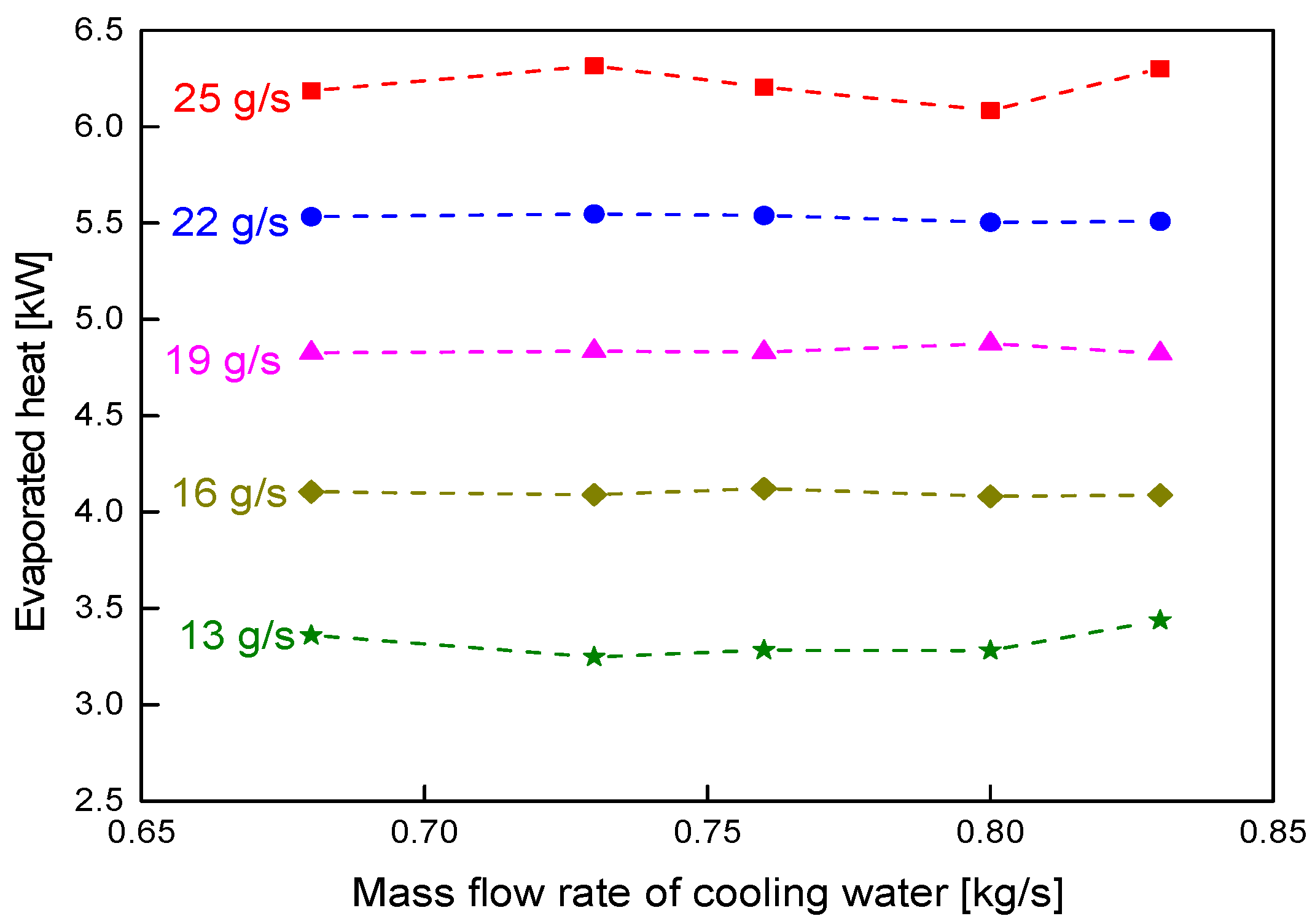
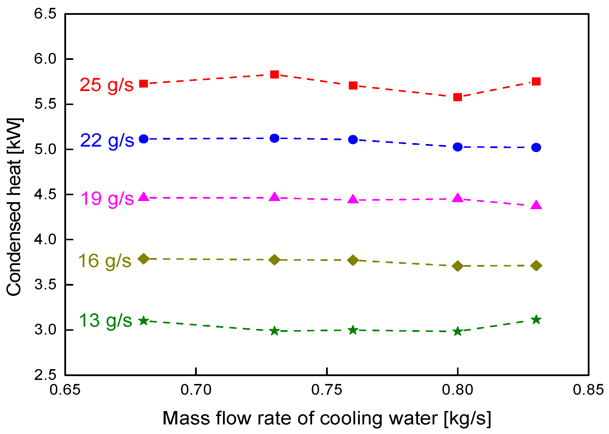
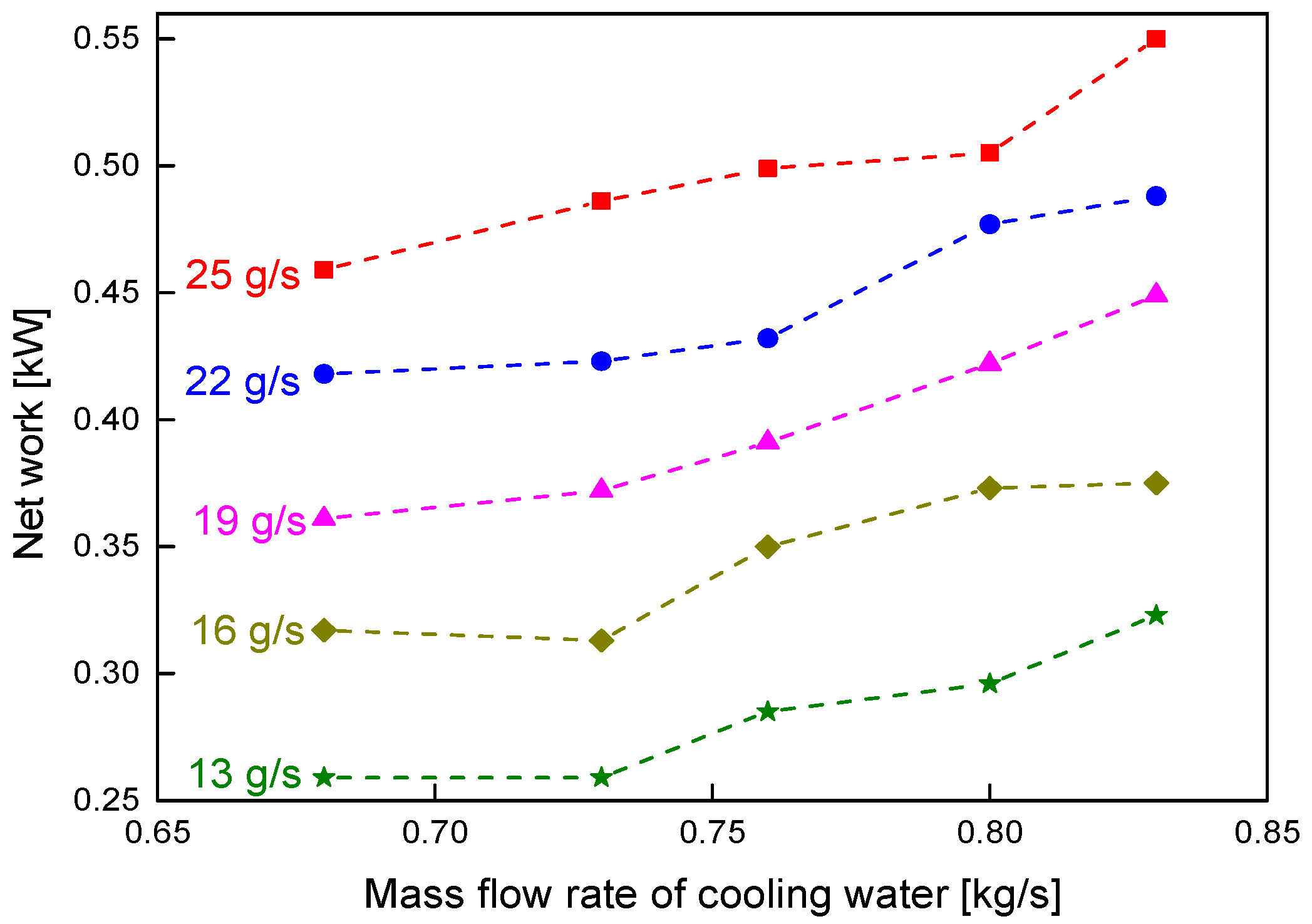
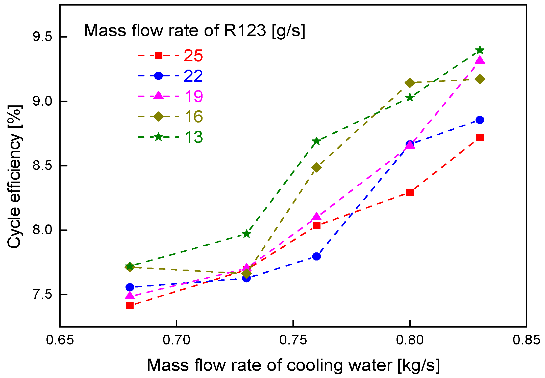
3.3. Effects of Cooling Water Mass Flow Rate
4. Conclusions
Author Contributions
Funding
Informed Consent Statement
Data Availability Statement
Conflicts of Interest
Nomenclature
| Symbols | ||
| h | Enthalpy | kJ/kg |
| Mass flow rate | kg/s | |
| ORC | Organic Rankine cycle | |
| P | Pressure | MPa |
| Heat flow | kW | |
| T | Temperature | K |
| W | Work | kW |
| Greeks | ||
| η | Efficiency | |
| Subscripts | ||
| 1, …4 | ||
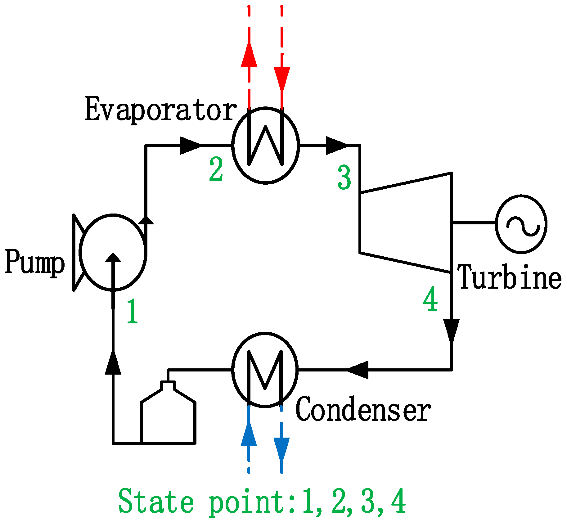
| b | Thermodynamic state points (Figure 1) | |
| c | Boiling temperature | |
| con | Critical point | |
| exp | Condensation | |
| net | Expander | |
| pump | Net output | |
| wf | Pump | |
| Working fluid | ||
References
- Lin, X.; Zuo, L.; Yin, L.; Su, W.; Ou, S. An idea to efficiently recover the waste heat of Data Centers by constructing an integrated system with carbon dioxide heat pump, mechanical subcooling cycle and lithium bromide-water absorption refrigeration cycle. Energy Convers. Manag. 2022, 256, 115398. [Google Scholar] [CrossRef]
- Su, W.; Hwang, Y.; Deng, S.; Zhao, L.; Zhao, D. Thermodynamic performance comparison of Organic Rankine Cycle between zeotropic mixtures and pure fluids under open heat source. Energy Convers. Manag. 2018, 165, 720–737. [Google Scholar] [CrossRef]
- Rahbar, K.; Mahmoud, S.; Al-Dadah, R.K.; Moazami, N.; Mirhadizadeh, S.A. Review of organic Rankine cycle for small-scale applications. Energy Convers. Manag. 2017, 134, 135–155. [Google Scholar] [CrossRef]
- Imran, M.; Haglind, F.; Asim, M.; Zeb, A.J. Recent research trends in organic Rankine cycle technology: A bibliometric approach. Renew. Sustain. Energy Rev. 2018, 81, 552–562. [Google Scholar] [CrossRef]
- Park, B.S.; Usman, M.; Imran, M.; Pesyridis, A. Review of Organic Rankine Cycle experimental data trends. Energy Convers. Manag. 2018, 173, 679–691. [Google Scholar] [CrossRef]
- Zinsalo, J.M.; Lamarche, L.; Raymond, J. Performance analysis and working fluid selection of an Organic Rankine Cycle Power Plant coupled to an Enhanced Geothermal System. Energy 2022, 245, 123259. [Google Scholar] [CrossRef]
- Su, W.; Zhao, L.; Deng, S. Simultaneous working fluids design and cycle optimization for Organic Rankine cycle using group contribution model. Appl. Energy 2017, 202, 618–627. [Google Scholar] [CrossRef]
- Liu, P.; Shu, G.; Tian, H. How to approach optimal practical Organic Rankine cycle (OP-ORC) by configuration modification for diesel engine waste heat recovery. Energy 2019, 174, 543–552. [Google Scholar] [CrossRef]
- Lecompte, S.; Huisseune, H.; van den Broek, M.; Vanslambrouck, B.; De Paepe, M. Review of organic Rankine cycle (ORC) architectures for waste heat recovery. Renew. Sustain. Energy Rev. 2015, 47, 448–461. [Google Scholar] [CrossRef]
- Lin, X.; Chen, C.; Yu, A.; Yin, L.; Su, W. Performance Comparison of Advanced Transcritical Power Cycles with High-Temperature Working Fluids for the Engine Waste Heat Recovery. Energies 2021, 14, 5886. [Google Scholar] [CrossRef]
- Lei, Y.; Ye, S.; Xu, Y.; Kong, C.; Xu, C.; Chen, Y.; Huang, W.; Xiao, H. Multi-objective optimization and algorithm improvement on thermal coupling of SOFC-GT-ORC integrated system. Comput. Chem. Eng. 2022, 164, 107903. [Google Scholar] [CrossRef]
- Lin, S.; Zhao, L.; Deng, S.; Ni, J.; Zhang, Y.; Ma, M. Dynamic performance investigation for two types of ORC system driven by waste heat of automotive internal combustion engine. Energy 2019, 169, 958–971. [Google Scholar] [CrossRef]
- Ping, X.; Yang, F.; Zhang, H.; Xing, C.; Zhang, W.; Wang, Y.; Yao, B. Dynamic response assessment and multi-objective optimization of organic Rankine cycle (ORC) under vehicle driving cycle conditions. Energy 2023, 263, 125551. [Google Scholar] [CrossRef]
- Zhao, R.; Zhang, H.; Song, S.; Tian, Y.; Yang, Y.; Liu, Y. Integrated simulation and control strategy of the diesel engine–organic Rankine cycle (ORC) combined system. Energy Convers. Manag. 2018, 156, 639–654. [Google Scholar] [CrossRef]
- Liu, C.; Gao, T. Off-design performance analysis of basic ORC, ORC using zeotropic mixtures and composition-adjustable ORC under optimal control strategy. Energy 2019, 171, 95–108. [Google Scholar] [CrossRef]
- Feng, Y.Q.; Hung, T.C.; Wu, S.L.; Lin, C.H.; Li, B.X.; Huang, K.C.; Qin, J. Operation characteristic of a R123-based organic Rankine cycle depending on working fluid mass flow rates and heat source temperatures. Energy Convers. Manag. 2017, 131, 55–68. [Google Scholar] [CrossRef]
- Yang, S.C.; Hung, T.C.; Feng, Y.Q.; Wu, C.J.; Wong, K.W.; Huang, K.C. Experimental investigation on a 3 kW organic Rankine cycle for low-grade waste heat under different operation parameters. Appl. Therm. Eng. 2017, 113, 756–764. [Google Scholar] [CrossRef]
- Li, Y.M.; Hung, T.C.; Wu, C.J.; Su, T.Y.; Xi, H.; Wang, C.C.; Lund, H.; Kaiser, M.J. Experimental investigation of 3-kW organic Rankine cycle (ORC) system subject to heat source conditions: A new appraisal for assessment. Energy 2021, 217, 119342. [Google Scholar] [CrossRef]
- Feng, Y.Q.; Wang, X.; Niaz, H.; Hung, T.C.; He, Z.X.; Zeb, A.J.; Xi, H. Experimental comparison of the performance of basic and regenerative organic Rankine cycles. Energy Convers. Manag. 2020, 223, 113459. [Google Scholar] [CrossRef]
- Li, X.; Lecompte, S.; Nieuwenhuyse, J.V.; Couvreur, K.; Markides, C.N. Experimental investigation of an organic Rankine cycle with liquid-flooded expansion and R1233zd(E) as working fluid. Energy Convers. Manag. 2021, 234, 113894. [Google Scholar] [CrossRef]
- Eyerer, S.; Wieland, C.; Vandersickel, A.; Spliethoff, H. Experimental study of an ORC (Organic Rankine Cycle) and analysis of R1233zd-E as a drop-in replacement for R245fa for low temperature heat utilization. Energy 2016, 103, 660–671. [Google Scholar] [CrossRef]
- Tian, H.; Liu, P.; Shu, G. Challenges and opportunities of Rankine cycle for waste heat recovery from internal combustion engine. Prog. Energy Combust. Sci. 2021, 84, 100906. [Google Scholar] [CrossRef]
- Moffat, R.J. Describing the uncertainties in experimental results. Exp. Therm. Fluid Sci. 1988, 1, 3–17. [Google Scholar] [CrossRef]


| Parameter | Instrument | Range | Accuracy |
|---|---|---|---|
| Pressure | Pressure transducer | 0~1.6 MPa | ±0.25% F.S. |
| Temperature | T-type thermocouple | −200~350 °C | ±0.1 °C |
| Mass flow rate of working fluid | Coriolis-type mass flow meter | 0~0.6 kg/s | ±0.15% F.S. |
| Cooling water flow rate | Electromagnetic flow meter | 0~8 m3·h−1 | ±0.5% F.S. |
| Oil flow rate | Turbine Flowmeter | 0~10 m3·h−1 | ±1% F.S. |
| Expansion work | Torque meter | 0~2 kW | ±0.5% F.S. |
| Consumed power | Digital power meter | 0~2 A | ±0.5% F.S. |
| Working Fluid | Molecular Structure | Molar Mass (g·mol−1) | Tc (°C) | Pc (MPa) | Tb (°C) | Acentric Factor |
|---|---|---|---|---|---|---|
| R123 | CF3CHCl2 | 152.93 | 183.68 | 3.66 | 27.82 | 0.282 |
| Items | Values |
|---|---|
| Heat source temperature (°C) | 130; 140; 150; 160 |
| Mass flow rate of working fluid (g/s) | 13; 16; 19; 22; 25 |
| Mass flow rate of cooling water (kg/s) | 0.83 |
| Inlet temperature of cooling water (°C) | 16 |
| Ambient temperature (°C) | 13 |
| Items | Values |
|---|---|
| Heat source temperature (°C) | 160 |
| Mass flow rate of working fluid (g/s) | 13; 16; 19; 22; 25 |
| Mass flow rate of cooling water (kg/s) | 0.68; 0.73; 0.76; 0.8; 0.83 |
| Inlet temperature of cooling water (°C) | 16 |
| Ambient temperature (°C) | 13 |
| State Point | Temperature (°C) | Pressure (MPa) | Enthalpy (kJ/kg) |
|---|---|---|---|
| 1 | 15.5 | 0.31 | 215.58 |
| 2 | 17.1 | 0.77 | 217.35 |
| 3 | 135.5 | 0.76 | 470.89 |
| 4 | 99.5 | 0.35 | 447.03 |
| Components | Value |
|---|---|
| Evaporator | 6.3 kW |
| Turbine | 0.59 kW |
| Condenser | 5.75 kW |
| Pump | 0.04 kW |
| Net work | 0.55 kW |
| Cycle efficiency | 8.7% |
Disclaimer/Publisher’s Note: The statements, opinions and data contained in all publications are solely those of the individual author(s) and contributor(s) and not of MDPI and/or the editor(s). MDPI and/or the editor(s) disclaim responsibility for any injury to people or property resulting from any ideas, methods, instructions or products referred to in the content. |
© 2023 by the authors. Licensee MDPI, Basel, Switzerland. This article is an open access article distributed under the terms and conditions of the Creative Commons Attribution (CC BY) license (https://creativecommons.org/licenses/by/4.0/).
Share and Cite
Gao, Y.; Song, Q.; Su, W.; Lin, X.; Sun, Z.; Huang, Z.; Gao, Y. Experimentally Identifying the Influences of Key Parameters for an Organic Rankine Cycle Using R123. Sustainability 2023, 15, 814. https://doi.org/10.3390/su15010814
Gao Y, Song Q, Su W, Lin X, Sun Z, Huang Z, Gao Y. Experimentally Identifying the Influences of Key Parameters for an Organic Rankine Cycle Using R123. Sustainability. 2023; 15(1):814. https://doi.org/10.3390/su15010814
Chicago/Turabian StyleGao, Yan, Qianxi Song, Wen Su, Xinxing Lin, Zhi Sun, Zhisheng Huang, and Yaping Gao. 2023. "Experimentally Identifying the Influences of Key Parameters for an Organic Rankine Cycle Using R123" Sustainability 15, no. 1: 814. https://doi.org/10.3390/su15010814
APA StyleGao, Y., Song, Q., Su, W., Lin, X., Sun, Z., Huang, Z., & Gao, Y. (2023). Experimentally Identifying the Influences of Key Parameters for an Organic Rankine Cycle Using R123. Sustainability, 15(1), 814. https://doi.org/10.3390/su15010814