
Simplified Super Twisting Sliding Mode Approaches of the Double-Powered Induction Generator-Based Multi-Rotor Wind Turbine System

 ,
,  ,
, 
 and
and
Abstract
:1. Introduction
- A new super twisting algorithm is proposed and confirmed.
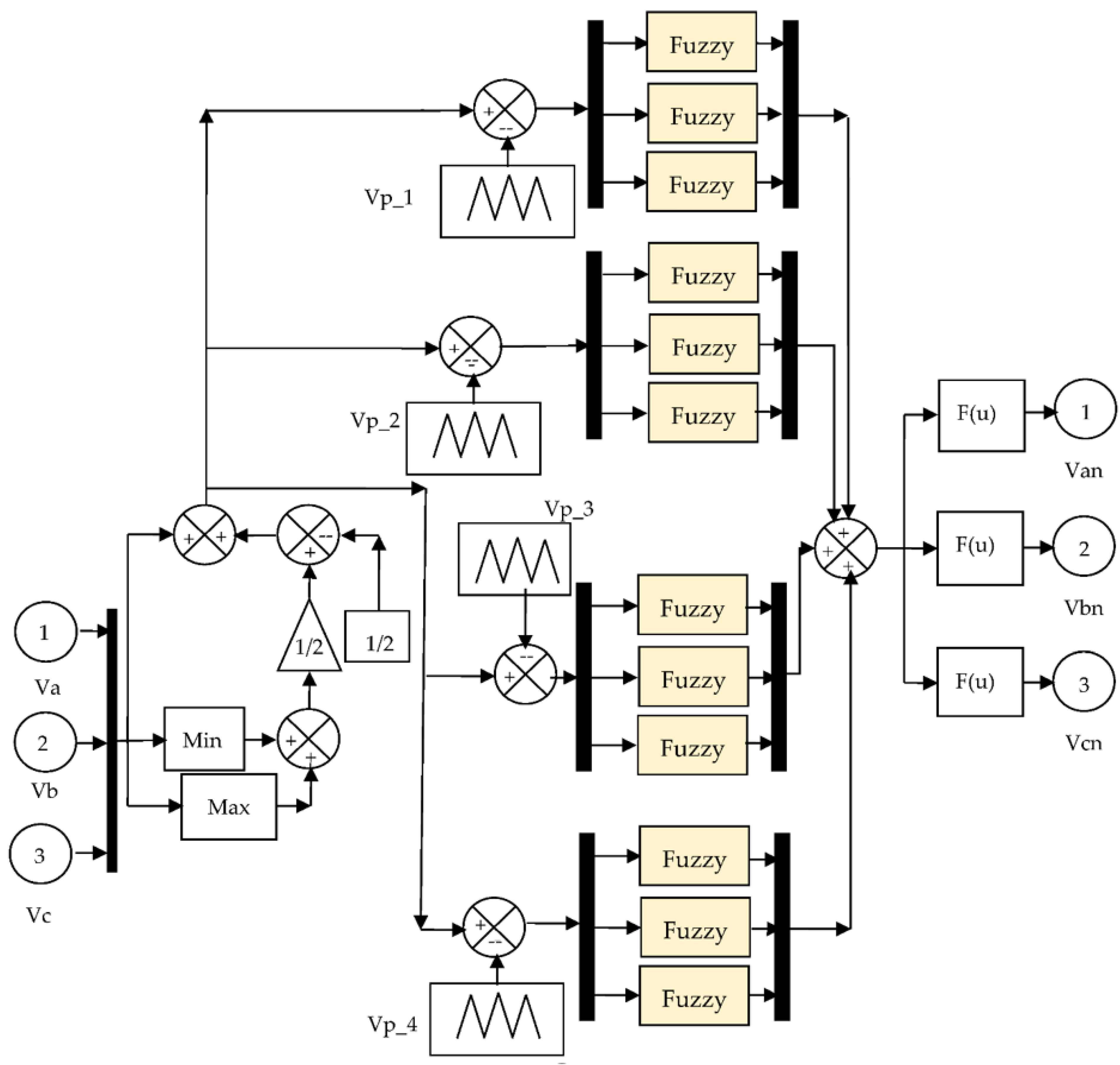
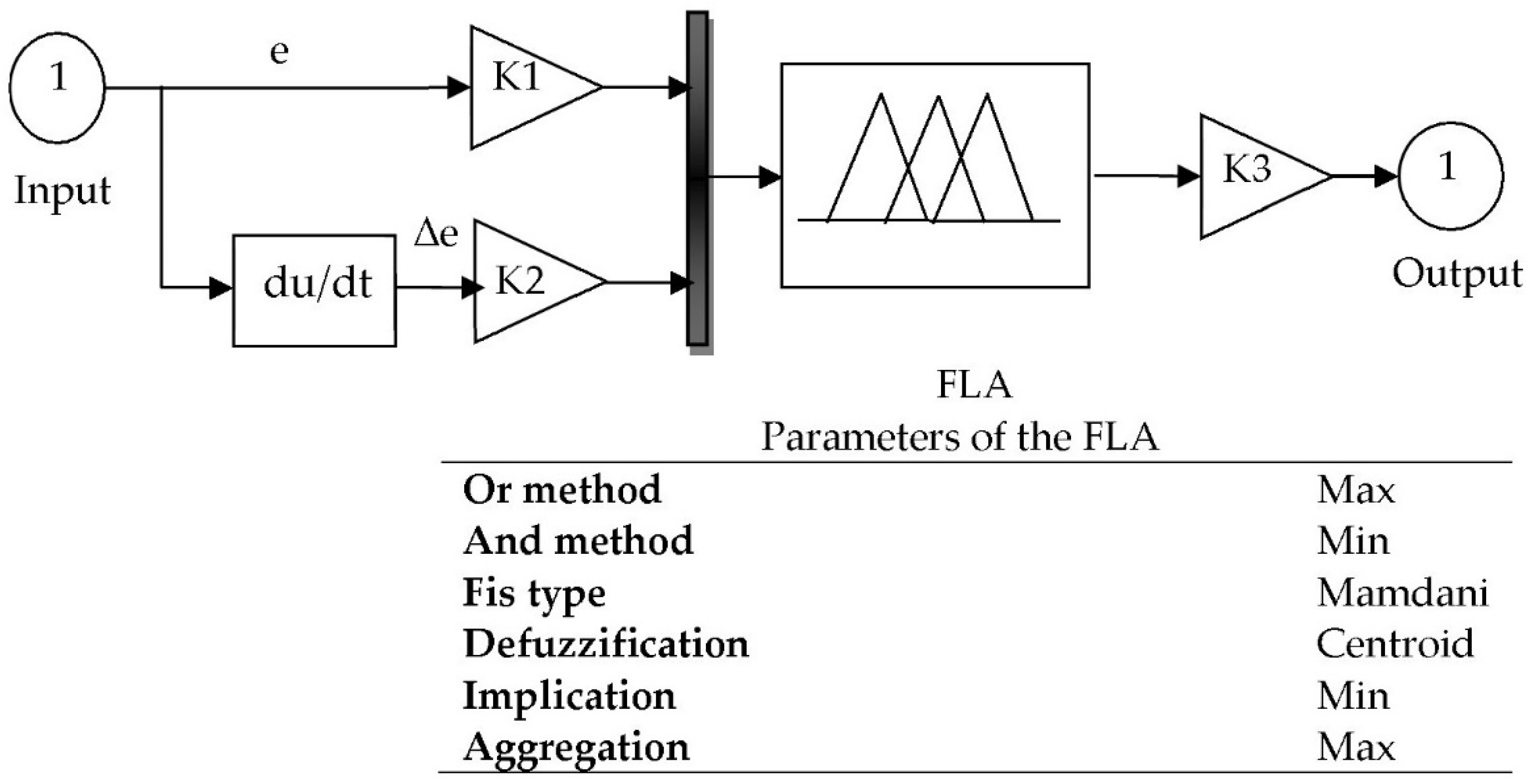
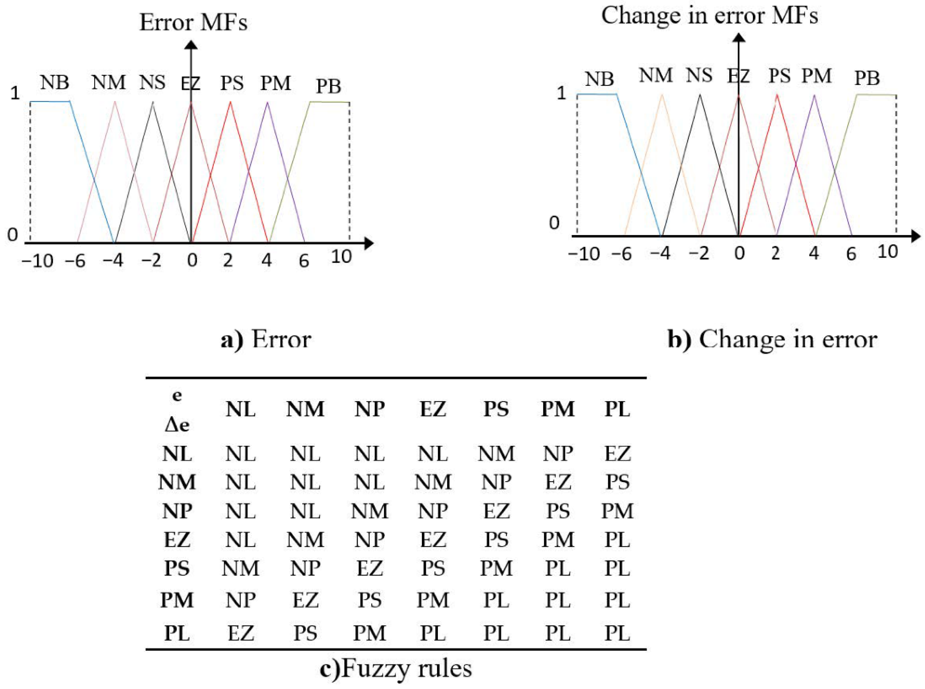
- A new space vector modulation (SVM) scheme is proposed based on the fuzzy logic controller to control the five-level inverter of the DPIG.
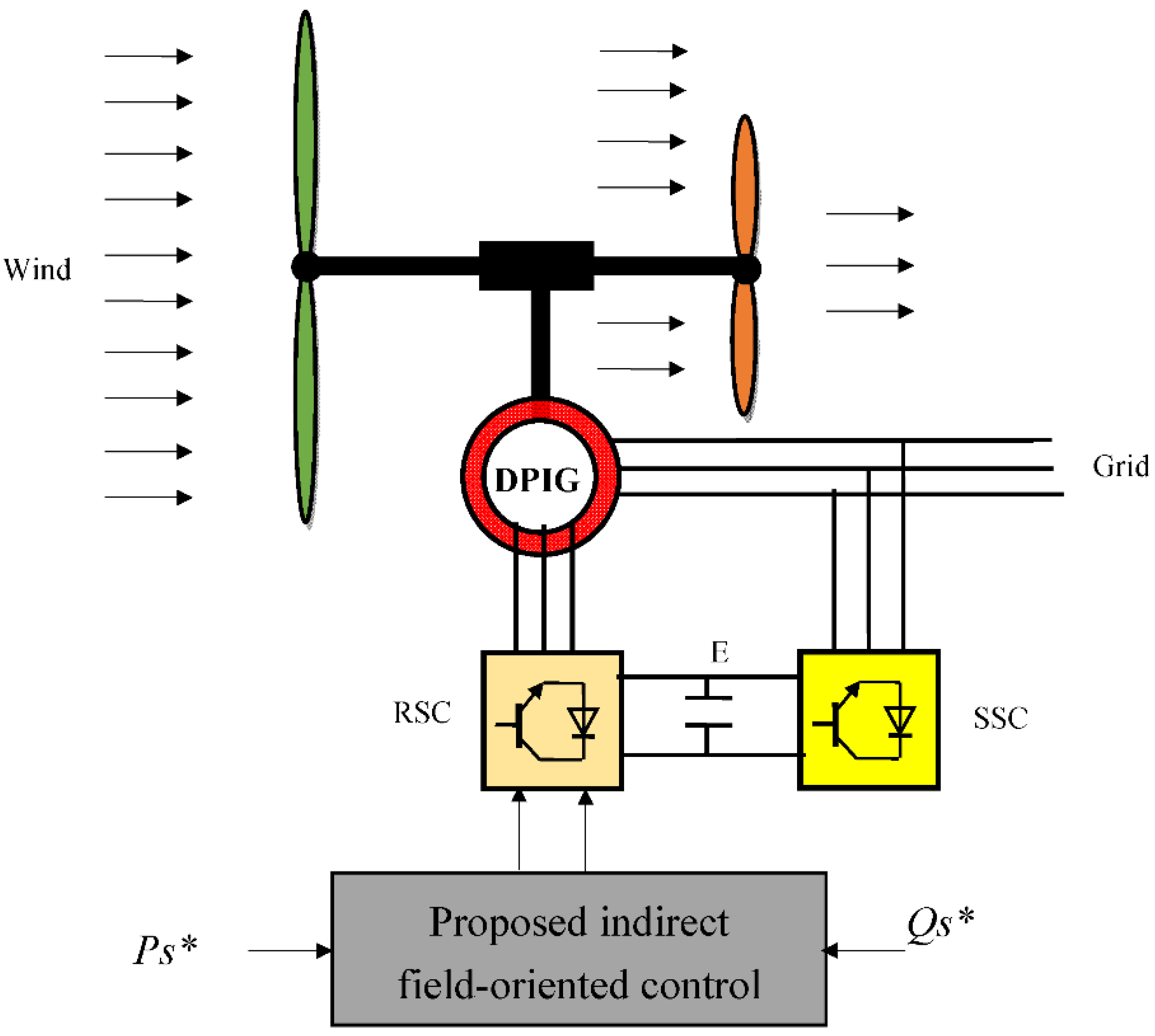
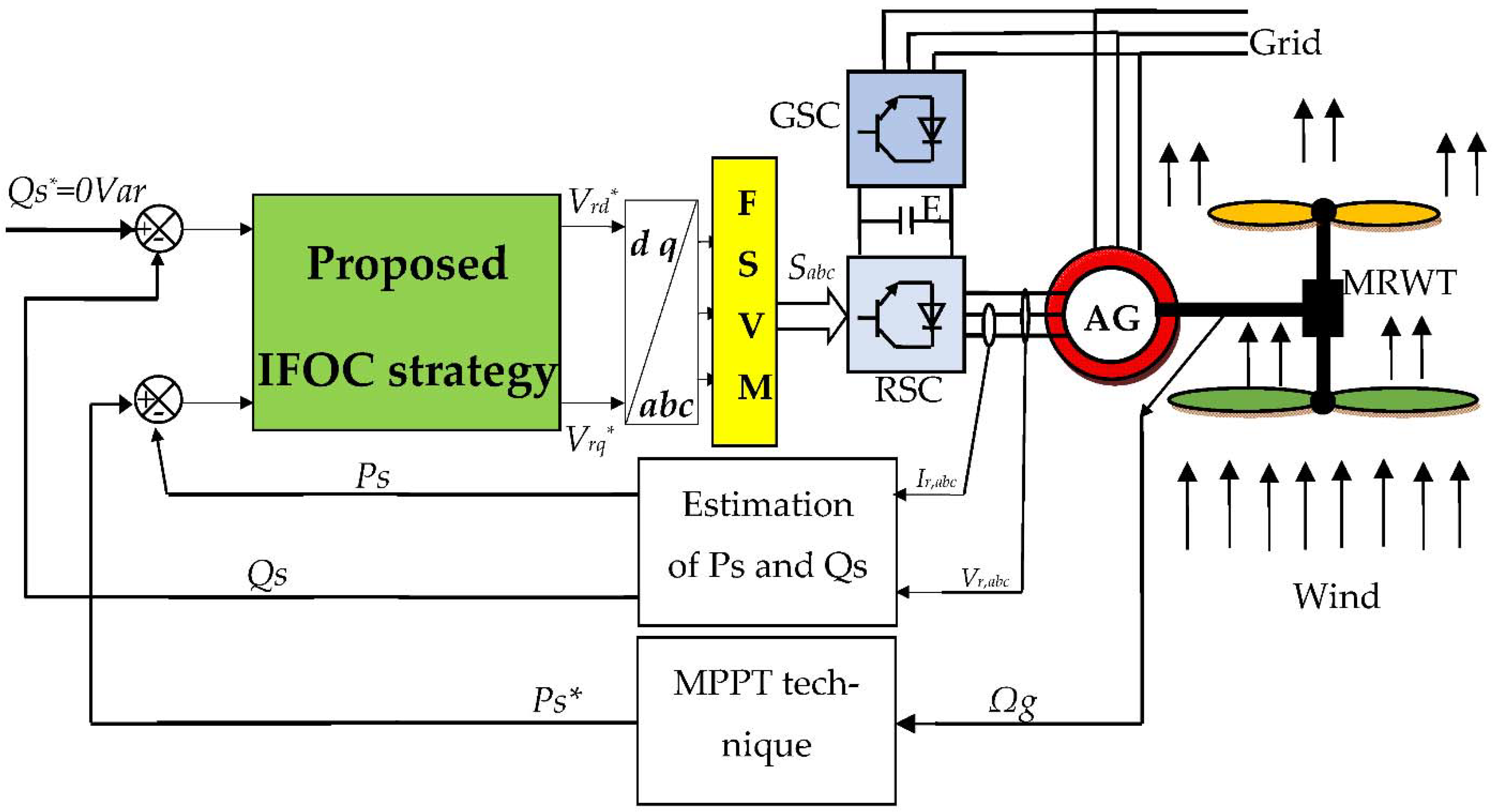
- A new IFOC strategy scheme is proposed to control the DPIG-based multi-rotor wind turbine system.
- A new SSTA algorithm is designed to improve the dynamic characteristics of DPIG-based multi-rotor wind turbine systems.
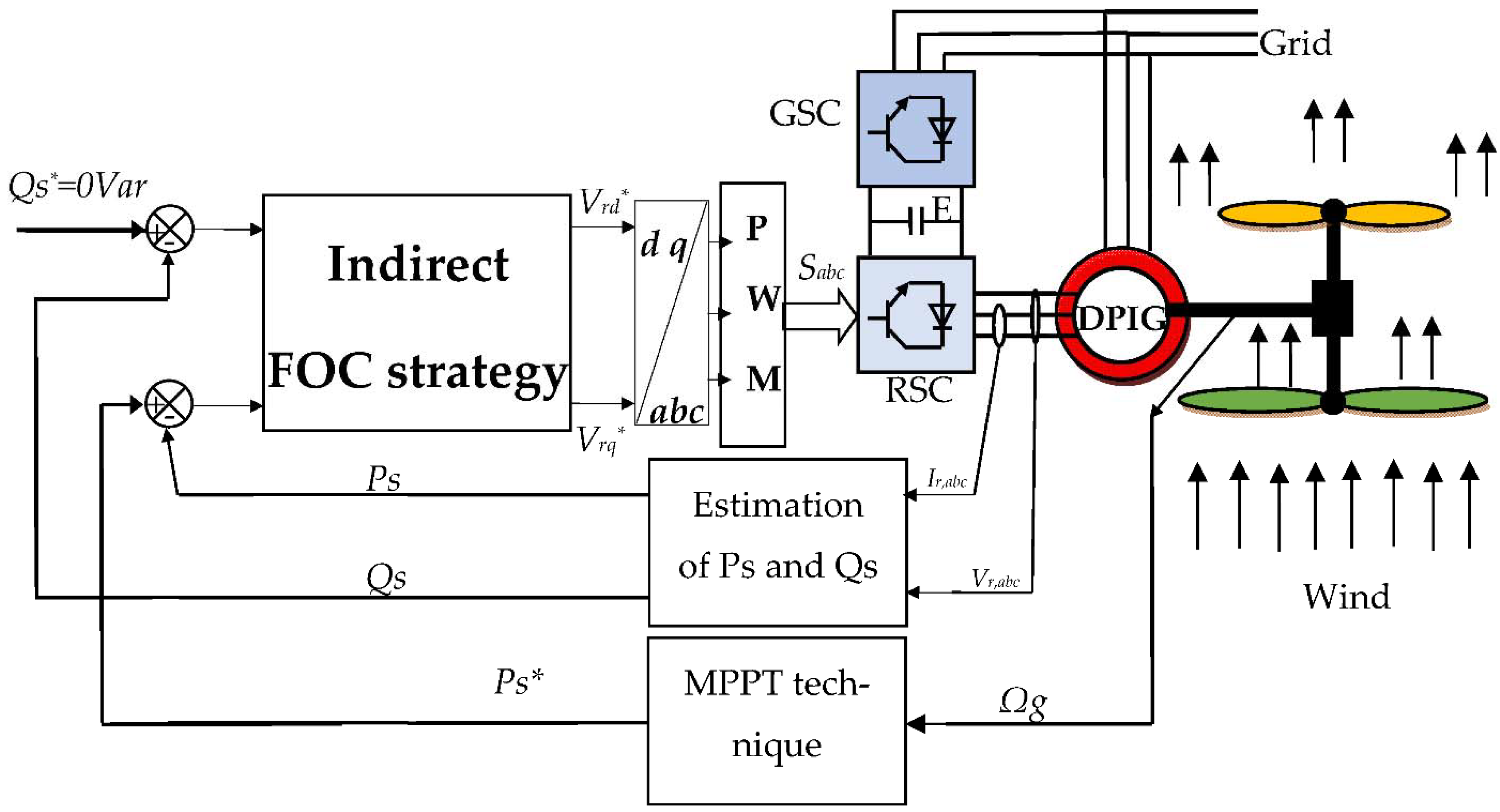
2. Multi-Rotor Wind Turbine System
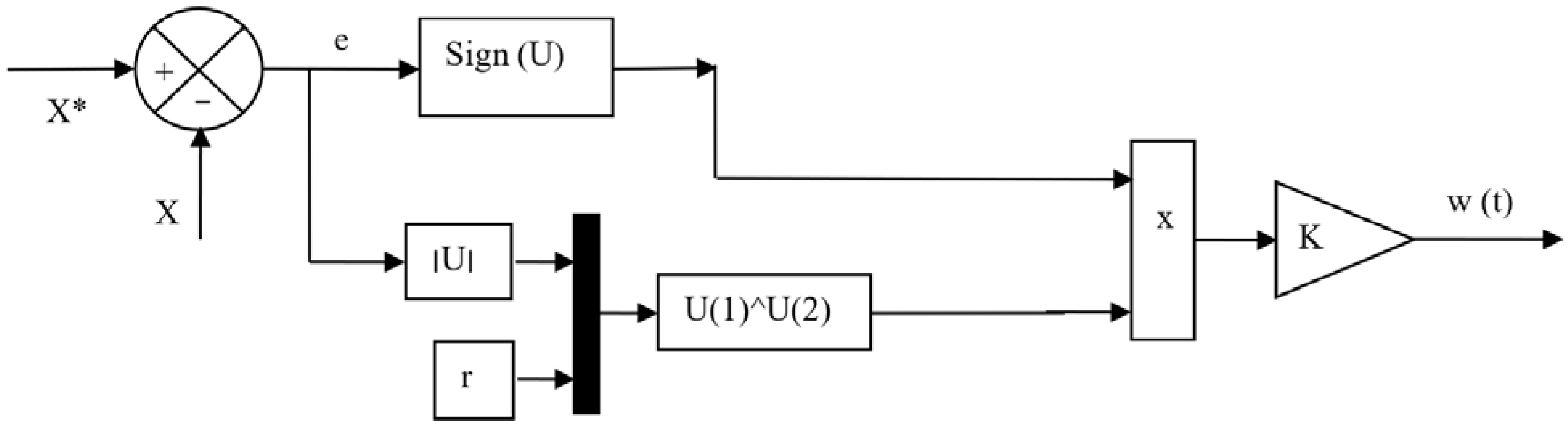
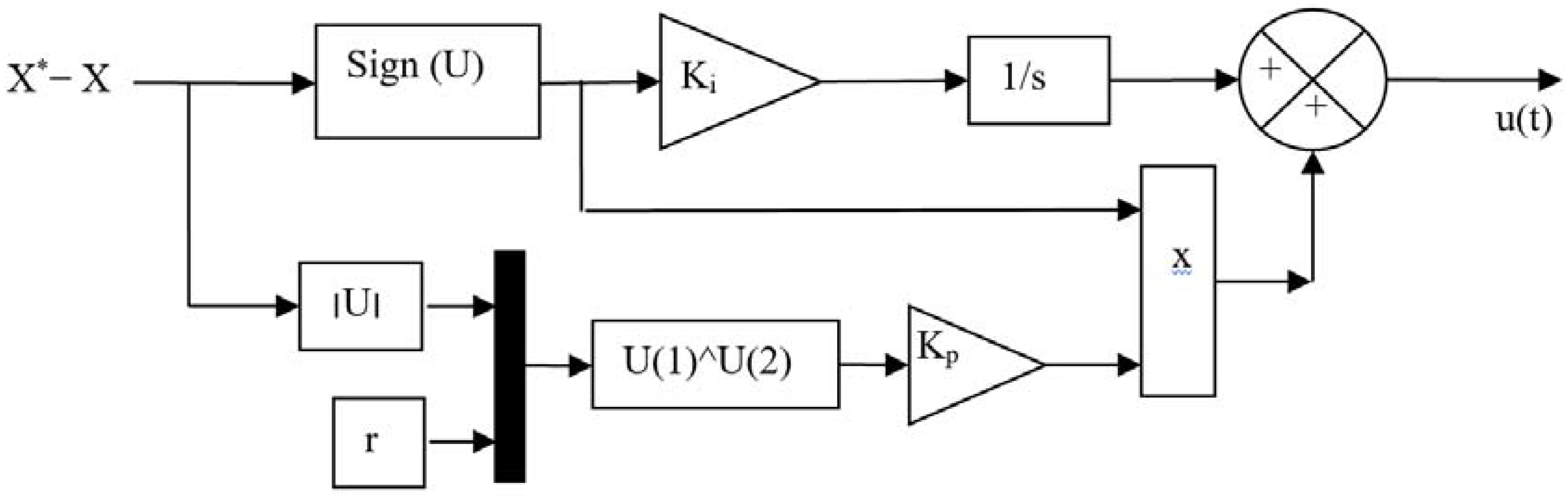
3. Simplified STA Controller
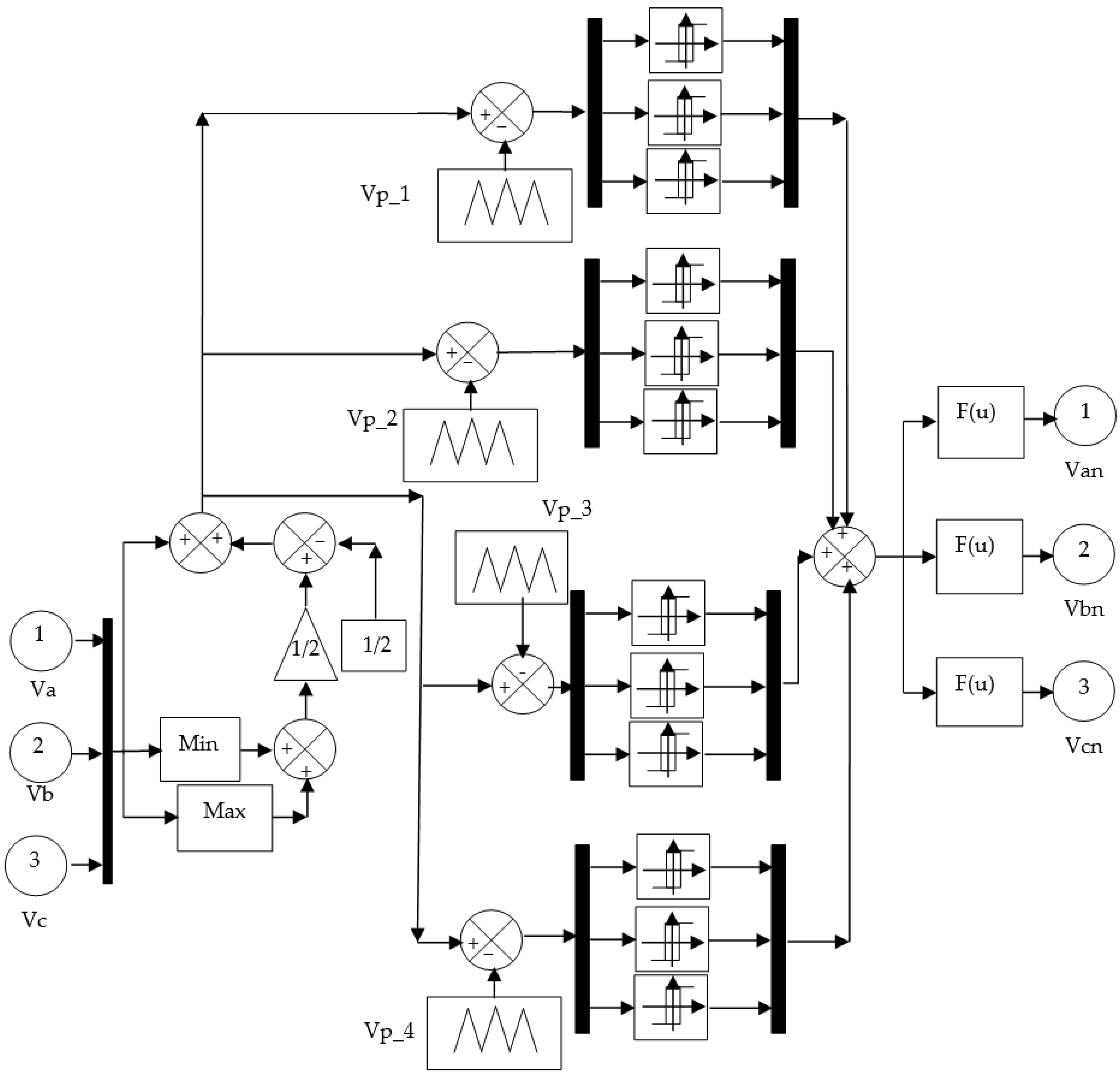
4. Proposed Five-Level Fuzzy SVM Strategy
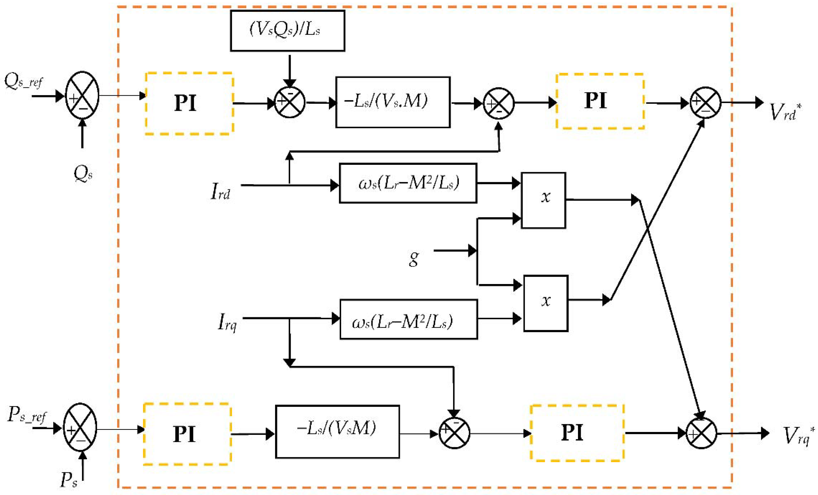
5. Traditional IFOC Strategy
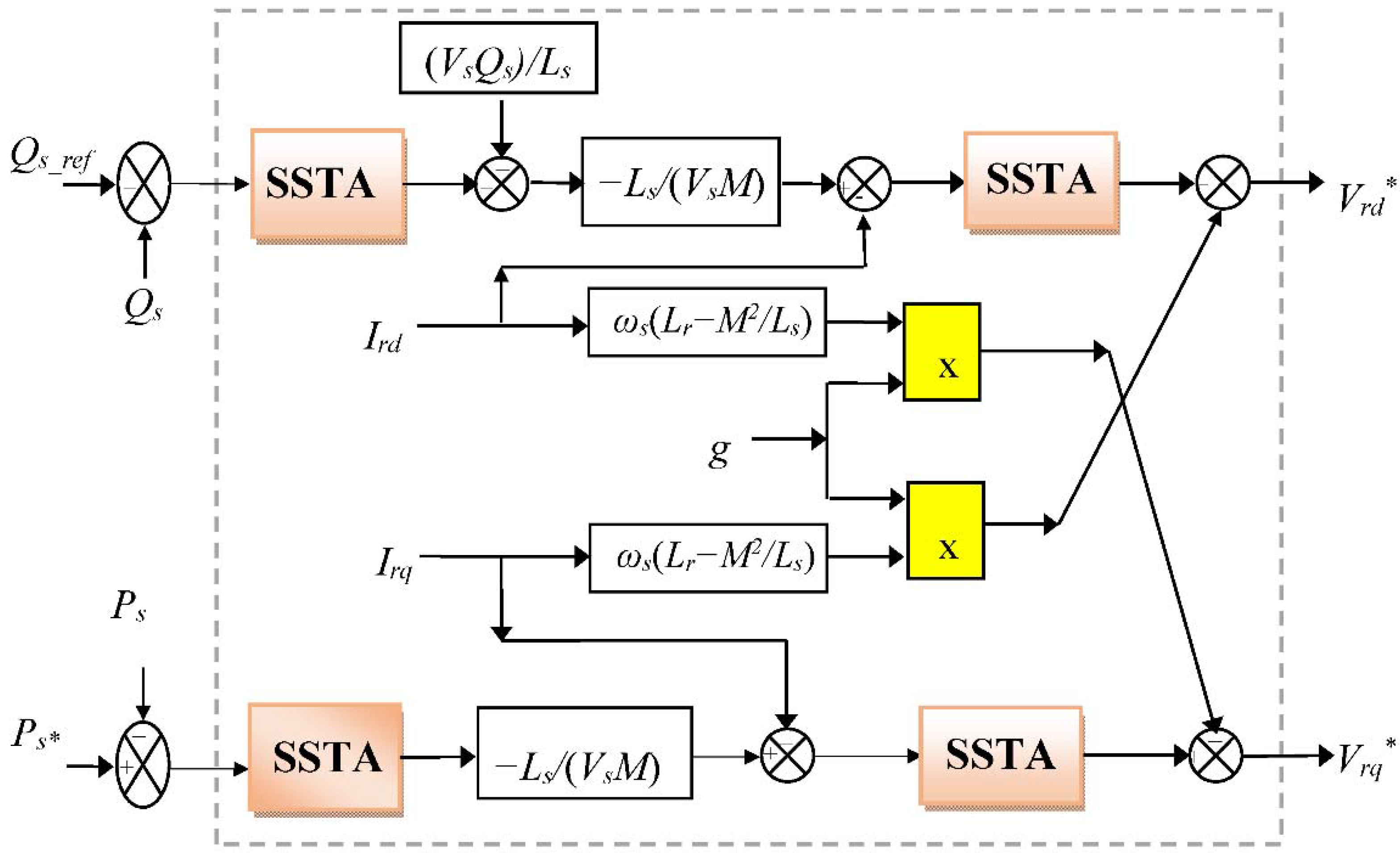
6. Proposed Indirect FOC Strategy
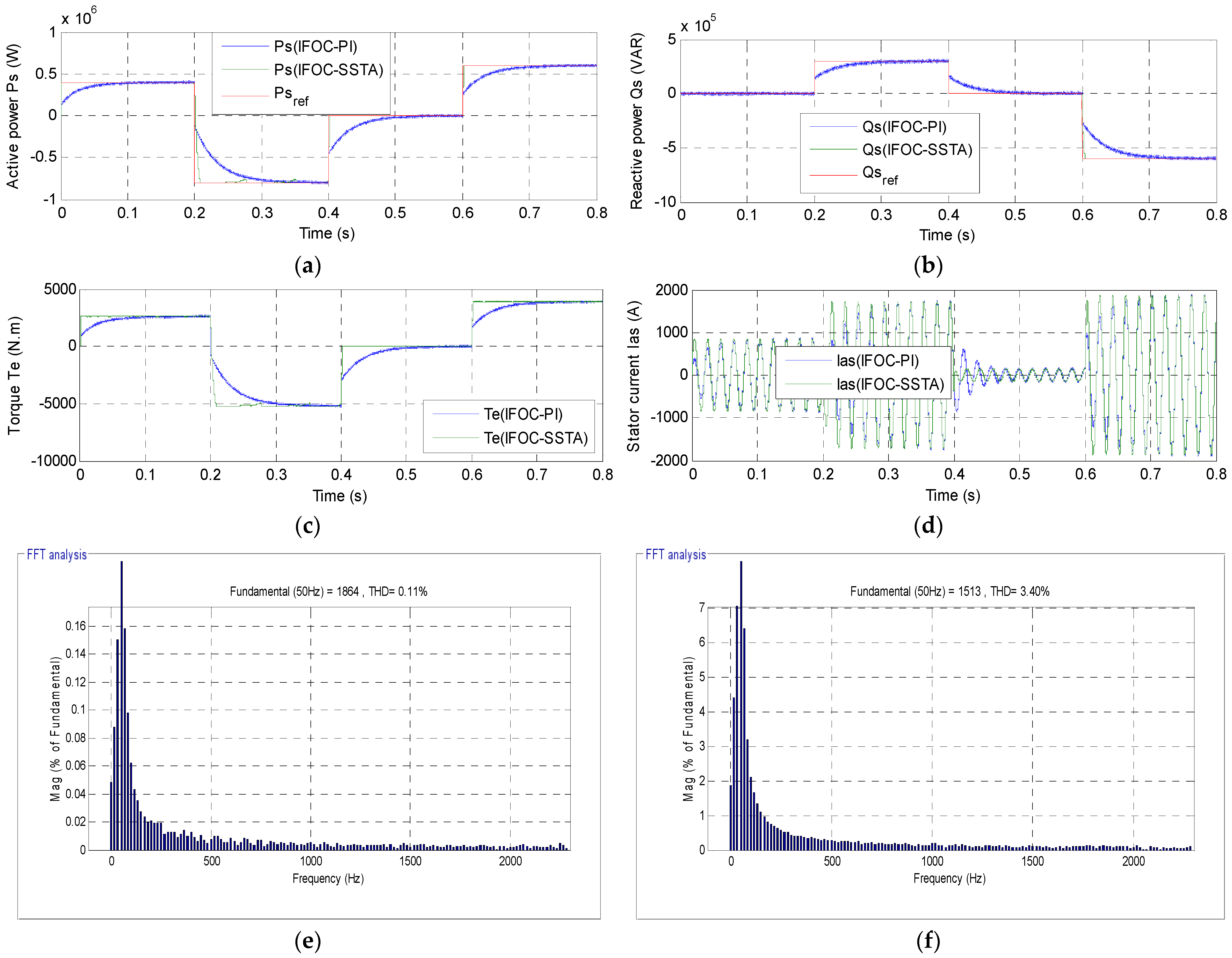
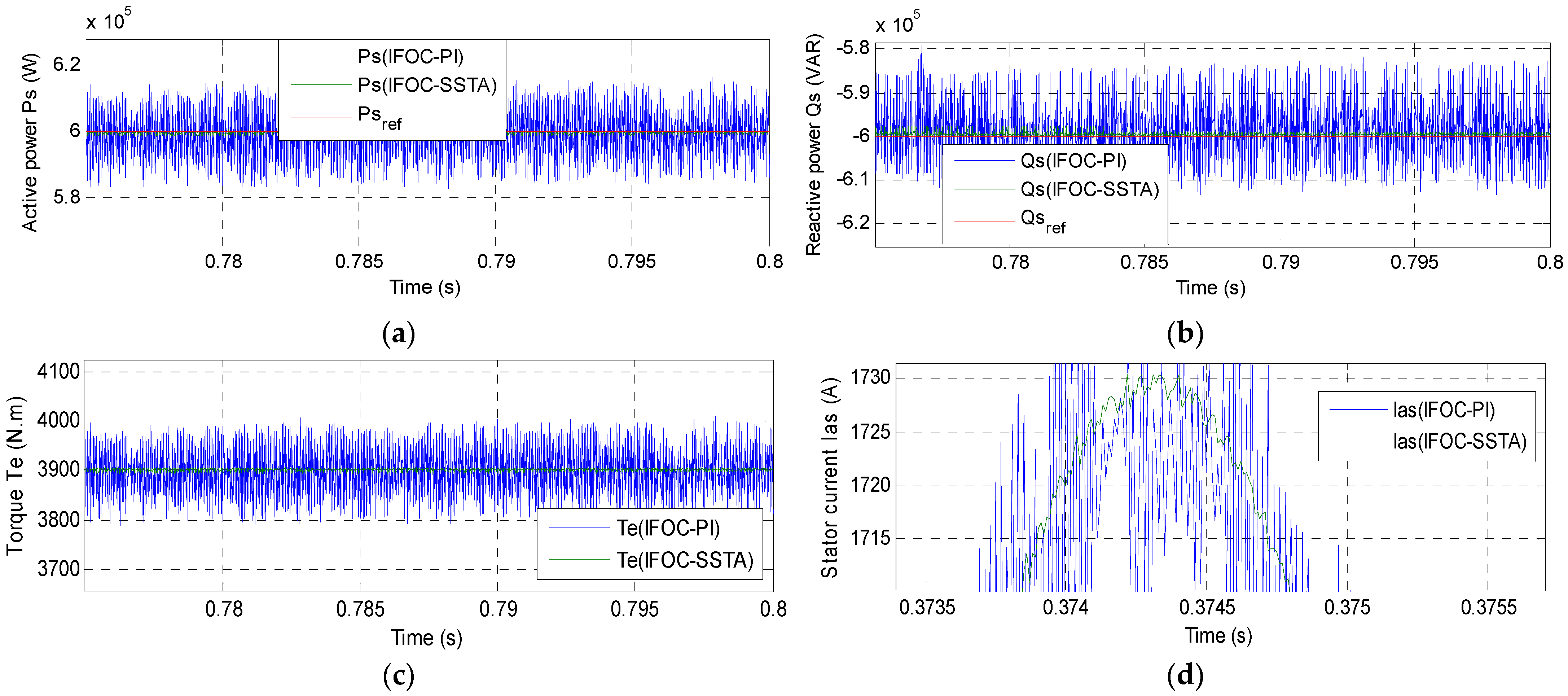
7. Results
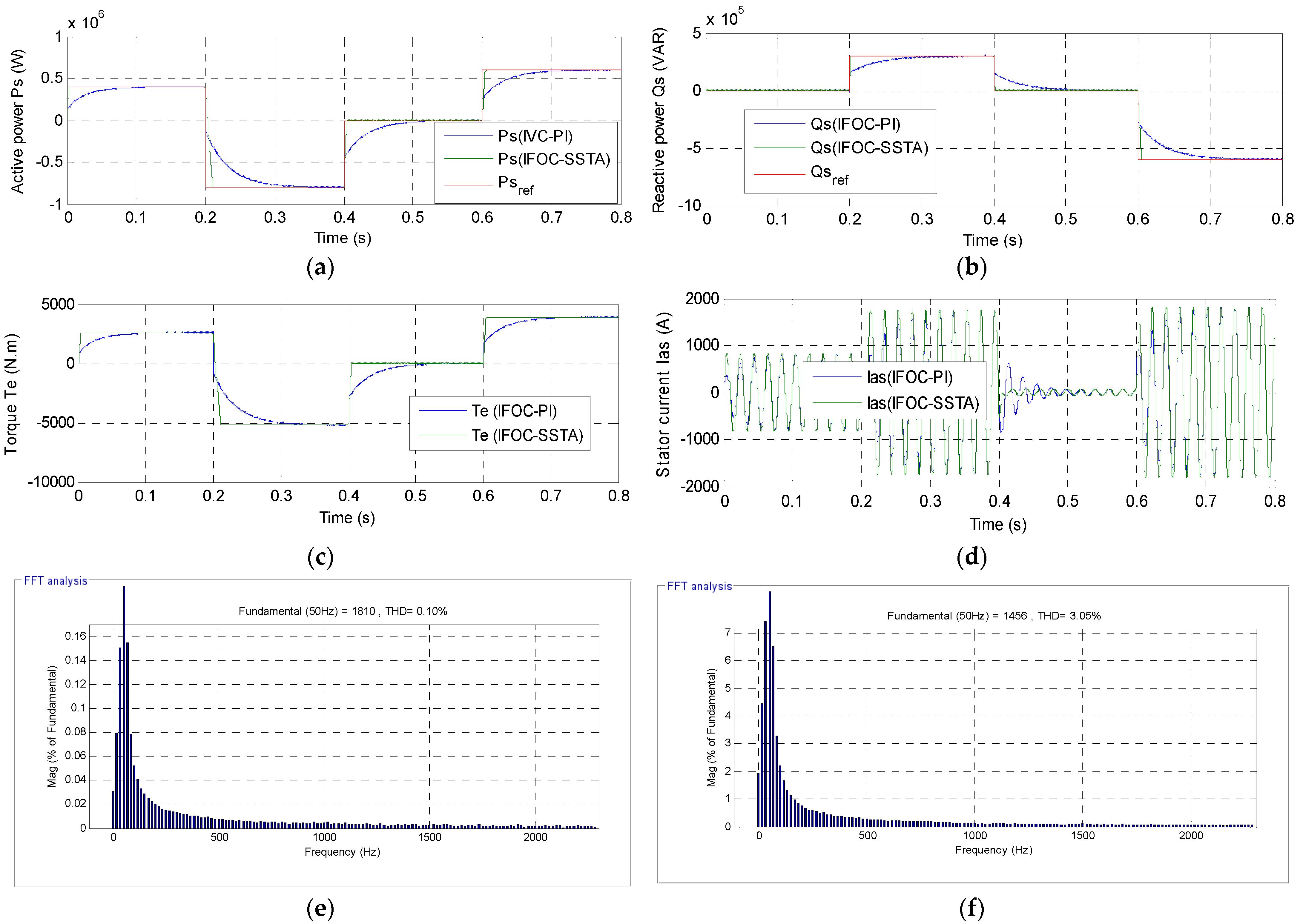
7.1. First Test
7.2. Second Test
8. Conclusions
- A new fuzzy SVM technology was introduced to control the five-level inverter to give a constant frequency at the inverter output, with this method confirmed by numerical simulation.
- A new simplified STA controller was proposed in this paper.
- A new indirect FOC strategy based on the simplified STA controller and the proposed five-level fuzzy SVM technique was presented and confirmed with numerical simulation.
- The robustness of the proposed indirect FOC strategy was presented.
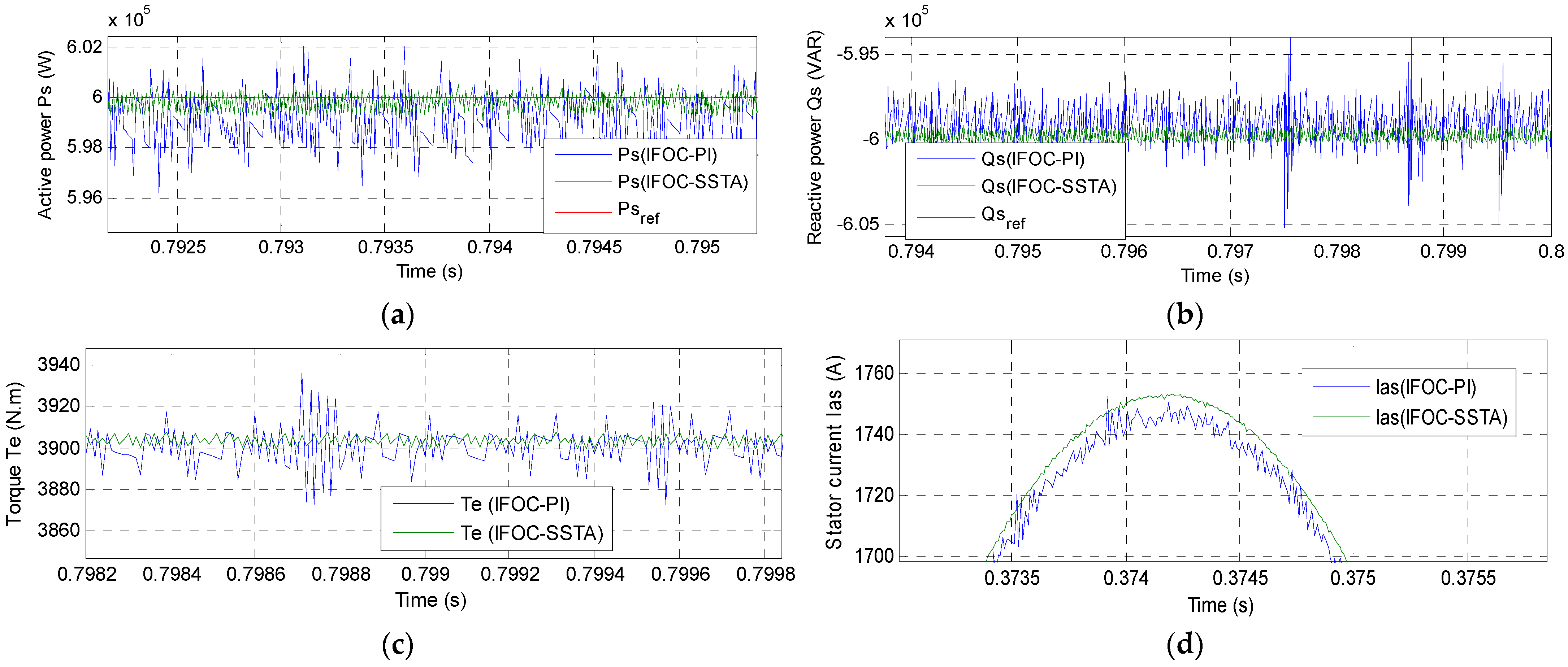
- The characteristics of the designed indirect FOC strategy was analyzed, showing that the undulations of the reactive power, stator current, torque, and active power were minimized.
Author Contributions
Funding
Institutional Review Board Statement
Informed Consent Statement
Data Availability Statement
Conflicts of Interest
References
- Mohamed Ahmed, S.A.; Montaser Abd El Sattar, M.A. Dynamic Performance and Effectiveness of Voltage Disturbances on the Improvement of Power Quality for Grid-Connected DFIG System Based Wind Farm. J. Electr. Eng. Electron. Control. Comput. Sci. 2020, 5, 25–30. Available online: https://jeeeccs.net/index.php/journal/article/view/126 (accessed on 9 April 2022).
- Talla, J.; Leu, V.Q.; Šmídl, V.; Peroutka, Z. Adaptive Speed Control of Induction Motor Drive With Inaccurate Model. IEEE Trans. Ind. Electron. 2018, 65, 8532–8542. [Google Scholar] [CrossRef]
- Wolkiewicz, M.; Tarchała, G.; Orłowska-Kowalska, T.; Kowalski, C.T. Online Stator Interturn Short Circuits Monitoring in the DFOC Induction-Motor Drive. IEEE Trans. Ind. Electron. 2016, 63, 2517–2528. [Google Scholar] [CrossRef]
- Candelo-Zuluaga, C.; Riba, J.-R.; Garcia, A. PMSM Parameter Estimation for Sensorless FOC Based on Differential Power Factor. IEEE Trans. Instrum. Meas. 2021, 70, 1–12. [Google Scholar] [CrossRef]
- Alexandrou, A.D.; Adamopoulos, N.K.; Kladas, A.G. Development of a Constant Switching Frequency Deadbeat Predictive Control Technique for Field-Oriented Synchronous Permanent-Magnet Motor Drive. IEEE Trans. Ind. Electron. 2016, 63, 5167–5175. [Google Scholar] [CrossRef]
- Amrane, F.; Chaiba, A.; Babes, B.E.; Mekhilef, S. Design and implementation of high performance field oriented control for grid-connected doubly fed induction generator via hysteresis rotor current controller. Rev. Roum. Sci. Tech.-Electrotech. Energ 2016, 61, 319–324. [Google Scholar]
- Eltamaly, A.M.; Al-Saud, M.; Sayed, K.; Abo-Khalil, A.G. Sensorless active and reactive control for DFIG wind turbines using opposition-based learning technique. Sustainability 2020, 12, 3583. [Google Scholar] [CrossRef]
- Habib, B.; Lemdani, S. Combining synergetic control and super twisting algorithm to reduce the active power undulations of doubly fed induction generator for dual-rotor wind turbine system. Electr. Eng. Electromech. 2021, 2021, 8–17. [Google Scholar]
- Benbouhenni, H.; Bizon, N. A Synergetic Sliding Mode Controller Applied to Direct Field-Oriented Control of Induction Generator-Based Variable Speed Dual-Rotor Wind Turbines. Energies 2021, 14, 4437. [Google Scholar] [CrossRef]
- Habib, B. Application of STA methods and modified SVM strategy in direct vector control system of ASG integrated to dual-rotor wind power: Simulation studies. Int. J. Smart Grid 2021, 5, 62–72. [Google Scholar]
- Habib, B. Amelioration effectiveness of torque and rotor flux control applied to the asynchronous generator (AG) for dual-rotor wind turbine using neural third-order sliding mode approaches. Int. J. Eng. Trans. C: Asp. 2022, 35, 517–530. [Google Scholar]
- Benbouhenni, H.; Bizon, N. Terminal Synergetic Control for Direct Active and Reactive Powers in Asynchronous Generator-Based Dual-Rotor Wind Power Systems. Electronics 2021, 10, 1880. [Google Scholar] [CrossRef]
- Amrane, F.; Chaiba, A. A novel direct power control for grid-connected doubly fed induction generator based on hybrid artificial intelligent control with space vector modulation. Rev. Sci. Tech.-Electrotech. Et Energ. 2016, 61, 263–268. [Google Scholar]
- Brando, G.; Dannier, A.; Spina, I. Performance Analysis of a Full Order Sensorless Control Adaptive Observer for Doubly-Fed Induction Generator in Grid Connected Operation. Energies 2021, 14, 1254. [Google Scholar] [CrossRef]
- Yahdou, A.; Hemici, B.; Boudjema, Z. Second order sliding mode control of a dual-rotor wind turbine system by employing a matrix converter. J. Electr. Eng. 2016, 16, 1–11. [Google Scholar]
- Erturk, E.; Sivrioglu, S.; Bolat, F.C. Analysis Model of a Small Scale Counter-Rotating Dual Rotor Wind Turbine with Double Rotational Generator Armature. Int. J. Renew. Energy Res. 2018, 8, 1849–1858. [Google Scholar]
- Fukami, T.; Momiyama, M.; Shima, K.; Hanaoka, R.; Takata, S. Steady-State Analysis of a Dual-Winding Reluctance Generator With a Multiple-Barrier Rotor. IEEE Trans. Energy Convers. 2008, 23, 492–498. [Google Scholar] [CrossRef]
- Worku, M.Y.; Hassan, M.A.; Abido, M.A. Real Time-Based under Frequency Control and Energy Management of Microgrids. Electronics 2020, 9, 1487. [Google Scholar] [CrossRef]
- Wang, L.; Kerrouche, K.D.E.; Mezouar, A.; Van Den Bossche, A.; Draou, A.; Boumediene, L. Feasibility Study of Wind Farm Grid-Connected Project in Algeria under Grid Fault Conditions Using D-Facts Devices. Appl. Sci. 2018, 8, 2250. [Google Scholar] [CrossRef] [Green Version]
- Han, Y.; Ma, R. Adaptive-Gain Second-Order Sliding Mode Direct Power Control for Wind-Turbine-Driven DFIG under Balanced and Unbalanced Grid Voltage. Energies 2019, 12, 3886. [Google Scholar] [CrossRef] [Green Version]
- Alhato, M.M.; Ibrahim, M.N.; Rezk, H.; Bouallègue, S. An Enhanced DC-Link Voltage Response for Wind-Driven Doubly Fed Induction Generator Using Adaptive Fuzzy Extended State Observer and Sliding Mode Control. Mathematics 2021, 9, 963. [Google Scholar] [CrossRef]
- Alhato, M.M.; Bouallègue, S.; Rezk, H. Modeling and Performance Improvement of Direct Power Control of Doubly-Fed Induction Generator Based Wind Turbine through Second-Order Sliding Mode Control Approach. Mathematics 2020, 8, 2012. [Google Scholar] [CrossRef]
- Djilali, L.; Badillo-Olvera, A.; Rios, Y.Y.; López-Beltrán, H.; Saihi, L. Neural High Order Sliding Mode Control for Doubly Fed Induction Generator based Wind Turbines. IEEE Lat. Am. Trans. 2022, 20, 223–232. [Google Scholar] [CrossRef]
- Halabi, L.M.; Alsofyani, I.M.; Lee, K.-B. Multi Open-/Short-Circuit Fault-Tolerance Using Modified SVM Technique for Three-Level HANPC Converters. IEEE Trans. Power Electron. 2021, 36, 13621–13633. [Google Scholar] [CrossRef]
- Habib, B. Utilization of an ANFIS-STSM algorithm to minimize total harmonic distortion. Int. J. Smart Grid 2020, 4, 56–67. [Google Scholar]
- Habib, B.; Boudjema, Z.; Belaidi, A. Direct power control with NSTSM algorithm for DFIG using SVPWM technique. Iranian J. Electr. Electron. Eng. 2021, 17, 1–11. [Google Scholar]
- Habib, B.; Boudjema, Z.; Belaidi, A. Neuro-second order sliding mode control of a DFIG supplied by a two-level NSVM inverter for wind turbine system. Iran. J. Electr. Electron. Eng. 2018, 14, 362–373. [Google Scholar]
- Fayssal, A.; Bruno, F.; Azeddine, C. Experimental investigation of efficient and simple wind-turbine based on DFIG-direct power control using LCL-filter for stand-alone mode. ISA Trans. 2021; 1–34, in press. [Google Scholar] [CrossRef]
- Evangelista, C.; Valenciaga, F.; Puleston, P. Active and Reactive Power Control for Wind Turbine Based on a MIMO 2-Sliding Mode Algorithm With Variable Gains. IEEE Trans. Energy Convers. 2013, 28, 682–689. [Google Scholar] [CrossRef]
- Habib, B.; Boudjema, Z.; Belaidi, A. Indirect vector control of a DFIG supplied by a two-level FSVM inverter for wind turbine system. Majlesi J. Electr. Eng. 2019, 13, 45–54. [Google Scholar]
- Tang, Z.; Akin, B. A New LMS Algorithm Based Deadtime Compensation Method for PMSM FOC Drives. IEEE Trans. Ind. Appl. 2018, 54, 6472–6484. [Google Scholar] [CrossRef]
- Yahdou, A.; Djilali, A.B.; Boudjema, Z.; Mehedi, F. Improved Vector Control of a Counter-Rotating Wind Turbine System Using Adaptive Backstepping Sliding Mode. J. Eur. Des Systèmes Autom. 2020, 53, 645–651. [Google Scholar] [CrossRef]
- Boulaam, K.; Mekhilef, A. Output power control of a variable wind energy conversion system. Rev. Sci. Techn.-Electrotech. Energ. 2017, 62, 197–202. [Google Scholar]
- Pan, L.; Zhu, Z.; Xiong, Y.; Shao, J. Integral Sliding Mode Control for Maximum Power Point Tracking in DFIG Based Floating Offshore Wind Turbine and Power to Gas. Processes 2021, 9, 1016. [Google Scholar] [CrossRef]
- Yahdou, A.; Hemici, B.; Boudjema, Z. Sliding mode control of dual rotor wind turbine system. Mediterr. J. Meas. Control 2015, 11, 412–419. [Google Scholar]
- Ibrahim, Y.; Semmah, A.; Patrice, W. Neuro-Second Order Sliding Mode Control of a DFIG based Wind Turbine System. J. Electr. Electron. Eng. 2020, 13, 63–68. [Google Scholar]
- Hamid, C.; Aziz, D.; Eddine, C.S.; Othmane, Z.; Mohammed, T.; Hasnae, E. Integral sliding mode control for DFIG based WECS with MPPT based on artificial neural network under a real wind profile. Energy Rep. 2021, 7, 4809–4824. [Google Scholar] [CrossRef]
- Ayrira, W.; Ourahoua, M.; El Hassounia, B.; Haddib, A. Direct torque control improvement of a variable speed DFIG based on a fuzzy inference system. Math. Comput. Simul. 2020, 167, 308–324. [Google Scholar] [CrossRef]
- Beniss, M.A.; El Moussaoui, H.; Lamhamdi, T.; El Markhi, H. Improvement of power quality injected into the grid by using a FOSMC-DPC for doubly fed induction generator. Int. J. Intell. Eng. Syst. 2021, 14, 556–567. [Google Scholar] [CrossRef]
- Quan, Y.; Hang, L.; He, Y.; Zhang, Y. Multi-Resonant-Based Sliding Mode Control of DFIG-Based Wind System under Unbalanced and Harmonic Network Conditions. Appl. Sci. 2019, 9, 1124. [Google Scholar] [CrossRef] [Green Version]
- Zeghdi, Z.; Barazane, L.; Bekakra, Y.; Larbi, A. Improved backstepping control of a DFIG based wind energy conversion system using ant lion optimizer algorithm. Period. Polytech. Electr. Eng. Comput. Sci. 2022, 66, 1–17. [Google Scholar] [CrossRef]
- Boudjema, Z.; Taleb, R.; Djerriri, Y.; Yahdou, A. A novel direct torque control using second order continuous sliding mode of a doubly fed induction generator for a wind energy conversion system. Turk. J. Elec-Trical Eng. Comput. Sci. 2017, 25, 965–975. [Google Scholar] [CrossRef] [Green Version]
- El Ouanjli, N.; Aziz, D.; El Ghzizal, A.; Mohammed, T.; Youness, E.; Khalid, M.; Badre, B. Direct torque control of doubly fed induction motor using three-level NPC inverter. Prot. Control Mod. Power Syst. 2019, 17, 1–9. [Google Scholar] [CrossRef] [Green Version]
- Benbouhenni, H.; Bizon, N. Advanced direct vector control method for optimizing the operation of a double-powered induction generator-based dual-rotor wind turbine system. Mathematics 2021, 9, 2297. [Google Scholar] [CrossRef]
- Yaichi, I.; Semmah, A.; Wira, P.; Djeriri, Y. Super-twisting sliding mode control of a doubly-fed induction generator based on the SVM strategy. Period. Polytech. Electr. Eng. Comput. Sci. 2019, 63, 178–190. [Google Scholar] [CrossRef]
- Benbouhenni, H. Synergetic control theory scheme for asynchronous generator based dual-rotor wind power. J. Electr. Eng. Electron. Control. Comput. Sci. 2021, 7, 19–28. Available online: https://jeeeccs.net/index.php/journal/article/view/215 (accessed on 9 April 2022).
- Nnem, L.N.; Lonla, B.L.; Sonfack, G.B.; Mbih, J. Review of a Multipurpose Duty-Cycle Modulation Technology in Electrical and Electronics Engineering. J. Electr. Eng. Electron. Control Comput. Sci. 2018, 4, 9–18. Available online: https://jeeeccs.net/index.php/journal/article/view/101 (accessed on 9 April 2022).


| Traditional Indirect FOC Technique | Proposed Indirect FOC Technique | |
|---|---|---|
| Type controller used | PI controller | SSTA controller |
| Rise time | High | Low |
| Modulation | PWM | Fuzzy SVM |
| Degree of complexity | Medium | High |
| Ease | Medium | Complicated |
| Simplicity of implementation | Medium | Complicated |
| Response dynamic | Slow | Quick |
| Robustness | Low | High |
| THD | High | Low |
| Power ripple | High | Low |
| Classical IFOC Technique | Proposed IFOC Technique | Ratios | |
|---|---|---|---|
| Torque ripple (N·m) | Around 60 | Around 5 | 91.66% |
| Reactive power ripple (VAR) | Around 8000 | Around 500 | 93.75% |
| Active power ripple (W) | Around 10,000 | Around 880 | 91.20% |
| Stator current (A) | Around 19 | Around 3 | 84.21% |
| Response Time | |||
|---|---|---|---|
| Torque | Reactive Power | Active Power | |
| Classical IFOC strategy | 0.12 s | 0.13 s | 0.12 s |
| Proposed IFOC strategy | 2.95 ms | 0.0023 s | 2.95 ms |
| Ratios | 97.54% | 98.23% | 97.54% |
| Response Time | ||||
|---|---|---|---|---|
| Torque | Reactive Power | Active Power | ||
| Proposed technique: IFOC-SSTA | 2.95 ms | 0.0023 s | 2.95 ms | |
| [36] | Direct power control | 18 ms | 17 ms | 18 ms |
| Neuro-second order SMC technique | 5 ms | 9 ms | 5 ms | |
| Traditional IFOC Strategy | Designed IFOC Technique | Ratios | |
|---|---|---|---|
| Torque ripple (N·m) | Around 172 | Around 11.60 | 93.35% |
| Reactive power ripple (VAR) | Around 25,000 | Around 500 | 98% |
| Active power ripple (W) | Around 30,000 | Around 5000 | 83.33% |
| Stator current (A) | Around 40 | Around 5 | 87.50% |
| References | Techniques | THD (%) |
|---|---|---|
| [37] | Field-oriented control with PI controllers | 0.77 |
| Super twisting algorithm (STA) | 0.28 | |
| [38] | Fuzzy DTC strategy | 2.40 |
| [39] | Fractional-order sliding mode control | 1.31 |
| [40] | Integral SMC technique | 9.71 |
| Multi-resonant-based sliding mode controller (MRSMC) | 3.14 | |
| [41] | Backstepping control | 2.19 |
| [6] | Field-oriented control | 3.7 |
| [12] | DPC control with PI controllers | 0.46 |
| DPC control with terminal synergetic controllers | 0.25 | |
| [42] | Direct torque control with second-order continuous SMC technique | 0.78 |
| [28] | DPC control with integral-proportional controllers | 0.43 |
| [9] | DFOC control with PI controllers | 1.45 |
| DFOC control with synergetic- SMC technique | 0.50 | |
| [13] | Field-oriented control with neuro-fuzzy controller | 0.78 |
| Field-oriented control with type-2 fuzzy logic controllers | 1.14 | |
| [43] | Multilevel DTC strategy | 1.57 |
| [32] | Vector control | 2.20 |
| Adaptive backstepping sliding mode control | 1.15 | |
| [44] | Traditional direct vector control | 1.65 |
| [45] | DPC with sliding mode controller | 1.66 |
| DPC with super twisting sliding mode controller | 0.11 | |
| Proposed IFOC strategy | First test | 0.10 |
| Second test | 0.11 |
Publisher’s Note: MDPI stays neutral with regard to jurisdictional claims in published maps and institutional affiliations. |
© 2022 by the authors. Licensee MDPI, Basel, Switzerland. This article is an open access article distributed under the terms and conditions of the Creative Commons Attribution (CC BY) license (https://creativecommons.org/licenses/by/4.0/).
Share and Cite
Benbouhenni, H.; Bizon, N.; Colak, I.; Thounthong, P.; Takorabet, N. Simplified Super Twisting Sliding Mode Approaches of the Double-Powered Induction Generator-Based Multi-Rotor Wind Turbine System. Sustainability 2022, 14, 5014. https://doi.org/10.3390/su14095014
Benbouhenni H, Bizon N, Colak I, Thounthong P, Takorabet N. Simplified Super Twisting Sliding Mode Approaches of the Double-Powered Induction Generator-Based Multi-Rotor Wind Turbine System. Sustainability. 2022; 14(9):5014. https://doi.org/10.3390/su14095014
Chicago/Turabian StyleBenbouhenni, Habib, Nicu Bizon, Ilhami Colak, Phatiphat Thounthong, and Noureddine Takorabet. 2022. "Simplified Super Twisting Sliding Mode Approaches of the Double-Powered Induction Generator-Based Multi-Rotor Wind Turbine System" Sustainability 14, no. 9: 5014. https://doi.org/10.3390/su14095014
APA StyleBenbouhenni, H., Bizon, N., Colak, I., Thounthong, P., & Takorabet, N. (2022). Simplified Super Twisting Sliding Mode Approaches of the Double-Powered Induction Generator-Based Multi-Rotor Wind Turbine System. Sustainability, 14(9), 5014. https://doi.org/10.3390/su14095014