Article

Sustainable Management of Salt Slag

by
Isabel Padilla
1,*,
Maximina Romero
1,
Sol López-Andrés
2 and
Aurora López-Delgado
1
1
“Eduardo Torroja” Institute for Construction Sciences, IETcc-CSIC, 28033 Madrid, Spain
2
Department of Mineralogy and Petrology, Faculty of Geology, University Complutense of Madrid, 28040 Madrid, Spain
*
Author to whom correspondence should be addressed.
Sustainability 2022, 14(9), 4887; https://doi.org/10.3390/su14094887
Submission received: 22 March 2022 / Revised: 14 April 2022 / Accepted: 15 April 2022 / Published: 19 April 2022
(This article belongs to the Special Issue Sustainable Environmental Management of Hazardous Wastes)

Abstract

:
The management of salt slag, a waste from the secondary aluminum industry, is associated with huge environmental concerns due to the risk of atmospheric pollution (emission of toxic gases), groundwater contamination (high salt content that can percolate and cause an increase in salinity) and soil unavailability (large extensions required for disposal). Therefore, the development of a sustainable process for its treatment and recovery is of the utmost importance. In this work, a two-step process for the valorization of salt slag was developed that rendered zeolite as the main added-value product and NaCl and NH3 as byproducts. First, salt slag was hydrolyzed at 90 °C and at a solid/water ratio of 1/3. More than 90% of salt and ~90% of ammonia were recovered. In a second step, the hydrolyzed slag was completely transformed into a NaP zeolite under mild hydrothermal conditions. The zeolite exhibited specific surface area (17 m2 g−1), cation exchange capacity (2.12 meq g−1) and zeta potential (−52 mV) values that represent good characteristics for use in the removal of metal ions from aqueous effluents. The transformation of salt slag into zeolite can be considered a sustainable process with a high contribution to the circular economy.

1. Introduction

Aluminum is a circular material capable of being recycled over and over again without losing its original properties [1]. It is one of the most recycled metals, with a huge number of applications due to its unique combination of characteristics, such as softness, lightness, strength, excellent electrical and heat conductivity, corrosion resistance, low density and low melting point [2]. These properties make it a fundamental resource for a circular economy, as a base material for sectors such as transport, construction, packaging and renewable energy technologies. Its application in these sectors explains the foreseeable growth of more than 50% in aluminum demand by 2050 (reaching approximately 107.8 million tons) [3]. European Aluminum’s Vision 2050 articulates a clear outlook for the development of a decarbonized, circular and energy-efficient aluminum value chain [4]. This strategy is based on reaching the full potential of the aluminum industry for the circular economy that will contribute directly to the UN’s Sustainable Development Goals (UNSDGs)—in particular, SDG 9 “Industry, innovation and infrastructure” and SDG 12 “Responsible consumption and production”, among others [5].
Recycled aluminum accounts for 36% of Europe’s aluminum metal supply, but by the middle of this century, the amount of aluminum available for recycling will more than double (8.6 million tons by 2050) [6]. This increased recycling could reduce CO2 emissions by more than 39 million tons and generate up to 6 billion euros per year for the European economy as a result of reduced imports [1,3].
One of the most important wastes generated in the secondary aluminum recycling process is salt slag [7]. It comes from scrap or slag melting processes, where fluxing salts (NaCl/KCl, up to 50% of the furnace charge) are added to prevent the oxidation of the aluminum metal on the surface of the melt. The salt protects the metal from the reactive atmosphere and facilitates its agglomeration and metal separation, thus increasing the metal recovery. Approximately 0.5 tons of salt slag are generated per ton of secondary aluminum produced [8,9,10,11,12]. The chemical and mineralogical composition of salt slag is very variable due to the different nature of the recycled aluminum scrap and the recycling processes used (type of furnace, salt requirements, etc.). The average composition includes 5–7% metallic aluminum, 15–30% metallic oxides (Al2O3, MgO, FeO, CaO, etc.) and 45–60% chloride (AlCl3, NaCl, KCl), along with other compounds, including nitrides (AlN), fluorides (CaF2, NaF, AlF3, Na3AlF6, etc.), carbides (Al4C3), sulfides (Al2S3), phosphides (AlP), etc. [8,9,13,14].
Salt slag is classified according to the European Catalogue for Hazardous Wastes with the code 10 03 08 *. This code indicates that the waste comes from aluminum thermal metallurgy, from a salt slag process and from secondary production, which must be mandatorily disposed of in a hazardous waste site. It is considered highly flammable (H3-A), irritant (H4), harmful (H5) and leachable (H13) [15,16]. If salt slag is improperly disposed of, the nearby area can be polluted by toxic metal ion leachate, which can affect the surface and groundwater. In addition, toxic, explosive and unpleasant-smelling gases (NH3, CH4, H2, PH3 and H2S) can be released due to their high reactivity in contact with air humidity or water, causing serious effects on living beings. The huge production of salt slag and the aforementioned hazardousness make the disposal of salt slag a worldwide problem [8,17,18,19].
Currently, the landfill disposal of salt slag is banned in most European countries, so this waste must be properly treated to minimize the environmental impact [20]. In Europe, there are more than 270 known aluminum-processing plants but only approximately 10 salt-slag-recycling facilities. They are located in Germany, France, Italy, Norway, the UK and Spain [7,8,21]. This means that some EU countries have to transport thousands of tons of salt slag thousands of kilometers for its processing, which involves an enormous economic and environmental cost.
Most of the processes described for the treatment of salt slag consist of milling and sieving of the as-obtained salt slag to recover metallic aluminum [22,23,24,25]. The rejected finest fraction is then subjected to a leaching process to dissolve and recover the salt content [17,26,27]. The recovered salt can be used as flux for melting aluminum scrap and in other markets [8,13,17]. During leaching, the released gases are generally combusted [8,27,28,29,30]. Peng et al. [31] described the use of ammonia to obtain different ammonia salts to be used as fertilizer, and the other gases evolved were absorbed on activated carbon. Concerning the non-metallic product (cake) obtained from salt leaching, its possible use in the construction industry was discussed [8,9,17,28,32]. Recent studies have focused on the process of extracting the aluminum content from the nonmetallic cake by acid or alkaline treatments and the use of the as-obtained aluminum solutions to prepare different kinds of materials, such as hydrocalumites, aluminates and hydrotalcites [1,33,34,35]. Nevertheless, these studies were performed at lab scale and, as a result of these processes, another new cake is generated that must also be treated.
Zeolites, crystalline aluminosilicates with structures based on a three-dimensional network of AlO4 and SiO4 tetrahedra, have been intensively used in many industrial applications (catalysis, water remediation, gas purification, among others) due to their regular porous structure and properties [36]. In recent decades, different kinds of waste have been used to manufacture zeolite, especially fly ash [37,38]. Recently, authors have developed a process to obtain zeolites using a non-saline aluminum waste with promising results [39,40]. This waste consisted of the finest fraction generated in the slag milling process in the tertiary industry. The process was based on a one-step hydrothermal synthesis procedure, which has also been envisaged as useful for salt slag from the secondary aluminum industry. To our knowledge, a process for the overall recovery of salt slag through the manufacture of zeolites without generation of any other solid residue has not been reported.
The objective of this work was to develop a process to obtain zeolite from salt slag without the generation of any waste. Thus, after the recovery of salt and gases, in a first stage, the entire non-metallic cake obtained was completely transformed into a zeolite. For this, salt slag was not subjected to any previous process of milling or sieving, i.e., the salt slag was used as generated in the aluminum industry. All the solid products and liquors generated in the process (hydrolyzed slag, salt, brine, gas, mother liquor and zeolite) and the initial as-received salt slag were well characterized.

2. Materials and Methods
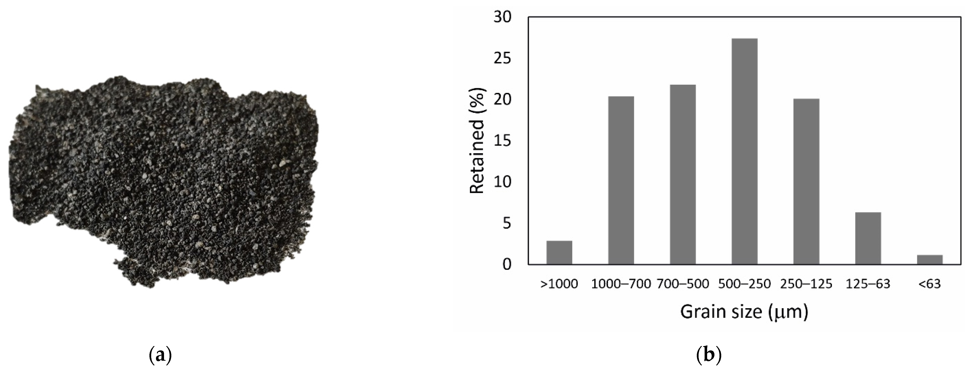
2.1. Raw Materials

The as-received sample of salt slag (provided by Alusigma S.A., Sotiello, Gijón, Spain) consisted of a dark-grayish granular solid with a grain size <1 mm (Figure 1a). Generally, heterogeneity (granulometric, compositional, etc.) is a characteristic of waste, and it is necessary to obtain representative samples before any characterization or use as a raw material to avoid any uncertainty in the reproducibility and accuracy of the results. Thus, the bulk sample (~2 kg) was divided into eight representative aliquots by a Laborette 27 rotary cone sample divider. The salt slag sample was not subjected to any process of milling. The granulometric determination showed that the sample was composed principally of medium–coarse grain sizes ranging between 125 and 1000 µm (Figure 1b).
The chemical composition of the salt slag is shown in Table 1. The major components, expressed as oxides, were Al2O3 and Na2O, along with chloride. From this result, the salt content in the initial slag was ~45%, and it consisted of NaCl. This is also confirmed by the XRD pattern shown in Figure 2. The total aluminum content was principally distributed in different phases, such as metallic aluminum, aluminum nitride (AlN), spinel (MgAl2O4) and corundum (Al2O3) (see magnification of Figure 2). Other phases tentatively assigned were quartz (SiO2) and silicon. Nevertheless, the background of the XRD pattern indicates the presence of amorphous or poorly crystalline phases, which could not be unambiguously identified. The quantitative analysis yielded contents of metallic aluminum and aluminum nitride of 10.88% and 5.56%, respectively. Both compounds are responsible for the hydrogen and ammonia gases that can be released when slags come into contact with water or moisture [18]. The loss of calcination (LOI) was 5.3 ± 0.1% and could be attributed to the decarbonation or dehydration of certain compounds included in the mineralogical composition of the salt slag.
For the synthesis of zeolites, a commercial sodium silicate neuter solution (Na2SiO3, Panreac, Castellar del Vallès, Barcelona, Spain) was added as the SiO2 source. Sodium hydroxide solution (1 M), prepared by dissolving NaOH pellets (98% NaOH, Panreac, Castellar del Vallès, Barcelona, Spain) in distilled water, was used as the alkalizing agent.

2.2. Methods

The process developed for the manufacture of zeolite from salt slag consisted of two stages. The first one concerned the recovery of brine by hydrolysis of salt slag, and the second one consisted of the transformation of the non-saline cake from the first stage into zeolite by a direct hydrothermal process. The recovery of the ammonia generated by the reaction of slag was studied in both stages.

2.2.1. Hydrolysis of Salt Slag

The hydrolysis of the salt slag was performed using the following procedure: 100 g aliquots of salt slag were placed into a glass balloon, and a peristaltic pump continuously dropped the corresponding amount of water. Tests were performed at salt slag/water ratios of 1/10 and 1/3 and temperatures of 25 and 90 °C. After filtration in a pressure filter, the hydrolyzed cake (hydrolyzed slag, HS) and filtrate were separated. The hydrolyzed slag was dried at 100 °C for 24 h and analyzed by XRF. The as-obtained HS was used in the synthesis of zeolite as the only source of aluminum. The filtrate (brine) was used to recover NaCl by evaporation/crystallization. Gas released during hydrolysis was recovered through a 4% boric acid solution to determine the ammonia content by titration with a standardized HCl solution. For the identification of the samples, the following nomenclature has been used: x/y-Tz, where x/y corresponds to the solid/liquid ratio used (1/3 or 1/10) and z corresponds to the temperature used (25 or 90 °C). Thus, a sample with an S/L ratio equal to 1/10 and treated at 90 °C will be named 1/10-T90.
The aim of the hydrolysis process was not only to obtain a slag with a very low salt content to be used in the synthesis of zeolite but also to recover the NaCl content in the initial salt slag and release ammonia gas during hydrolysis.

2.2.2. Synthesis of Zeolite

The synthesis of zeolite was carried out by a hydrothermal method, as described by Sánchez-Hernández et al. [41], using the hydrolyzed salt as a reactant, along with Na2SiO3 and NaOH solutions. Experiments were carried out in a Teflon-lined autoclave (Parr, 1 L volume) with vigorous and continuous stirring at 100 °C for 24 h and at 120 °C for 5 h. All the reactants were placed into the reactor, and the synthesis was performed in a one-step process. For the objective of synthesizing zeolite-type NaP (Na6Al6Si10O32·12H2O), a fixed Si/Al ratio of 1.7 was used by adding the corresponding amount of the silicate solution. After finishing the experiments, solid products were separated from the mother liquor by pressure filtration, washed with distilled water and dried at 80 °C for 24 h.

2.3. Characterization Techniques

The salt slag, hydrolyzed slag and zeolite were characterized by different analytical techniques. The granulometry was determined by application of the Standard ASTM C 136-01 [42]; for grain sizes lower than 700 μm, the PHI scale [43] was used; the finest grain size was measured by laser using the Honeywell Microtrac X100 equipment (Verder Scientific; Haan, Duesseldorf, Germany). The chemical composition was determined by X-ray fluorescence (XRF) in a wavelength-dispersive spectrometer (S8 Tiger model, Bruker, Champs–sur–Marne, France). Pressed pellets of 10 g raw material without additives were prepared for the measurements. Loss on ignition (LOI) was calculated by heating the samples at 1000 °C for 1 h in a Pt crucible. The aluminum nitride in the salt slag was analyzed by the Kjeldahl method using a digester Foss Tecator (mod. 2006) and its distilling unit (mod. 1002) (Foss Iberia, Barcelona, Spain), and subsequent titration with 0.01 M HCl. The metallic aluminum content was determined by treating samples with a 10% HCl solution to solve aluminum acid soluble compounds; the filtrate was analyzed by atomic absorption spectrometry (AAS) using Varian Spectra model AA-220FS equipment (Varian, Inc., Netherlands). The different effluents of the process (filtrate from the hydrolysis process and mother liquor from the synthesis of zeolite) were analyzed by an inductively coupled plasma optical emission spectrometer, Spectro Arcos ICP–OES (Spectro Analytical Instruments GmbH, Kleve, Germany). The pH and conductivity values were simultaneously measured by a multimeter provided with the two corresponding electrodes (MM41, Crison, Hach Lange Spain, S.L.U., L’Hospitalet de Llobregat, Barcelona, Spain). The amorphous or crystalline nature of the raw materials and products was determined by X-ray diffraction (XRD) (D8 Advance model, Bruker, Champs–sur–Marne, France) using CuKα radiation. The diffractograms were recorded in the interval 2θ = 10–60° with a scan rate of 0.07 s per step. XRD data processing was performed with the EVA Difrac Plus 13.0 program, and crystalline phase identification was performed with the Powder Diffraction File (PDF) database. The morphology of the zeolite was examined by scanning electron microscopy (SEM) in a Hitachi S4800 microscope (Hitachi High–Tech Europe GmbH, Krefel, Germany) on a previously graphite-coated sample. Textural characterization of zeolite was performed by determination of nitrogen adsorption/desorption isotherms at 77 K in an ASAP 2010 Micromeritics Instrument Corporation (Norcross, GA, USA). Before the measurements, the samples were outgassed at 60 °C in vacuum for 24 h. The BET specific surface area (SBET) was calculated by the BET method in the relative pressure range of 0.0015 to 0.3007. The external area (SEXT) was calculated by the t-plot method from the slope of the linear fit in the thickness range (t) of 0.35 to 0.50 nm according to the Harkinse–Jura equation. The pore size distribution was calculated using the Barrett–Joyner–Halenda (BJH) method in the adsorption branches. A study of the chemistry of the zeolite surface was carried out by determination of the zeta potential (PZ) and the cation exchange capacity (CEC). PZ was measured by a laser Doppler electrophoresis analyzer (ZetaSizer Nano, Malvern Instruments Ltd., Worcestershire, UK) using 0.005 g of sample in 100 mL of aqueous dispersion at 25 °C. The cation exchange capacity of the zeolite was determined by the NH4 ion exchange method with a 1 M NH4Cl solution (pH ~7).

3. Results and Discussion

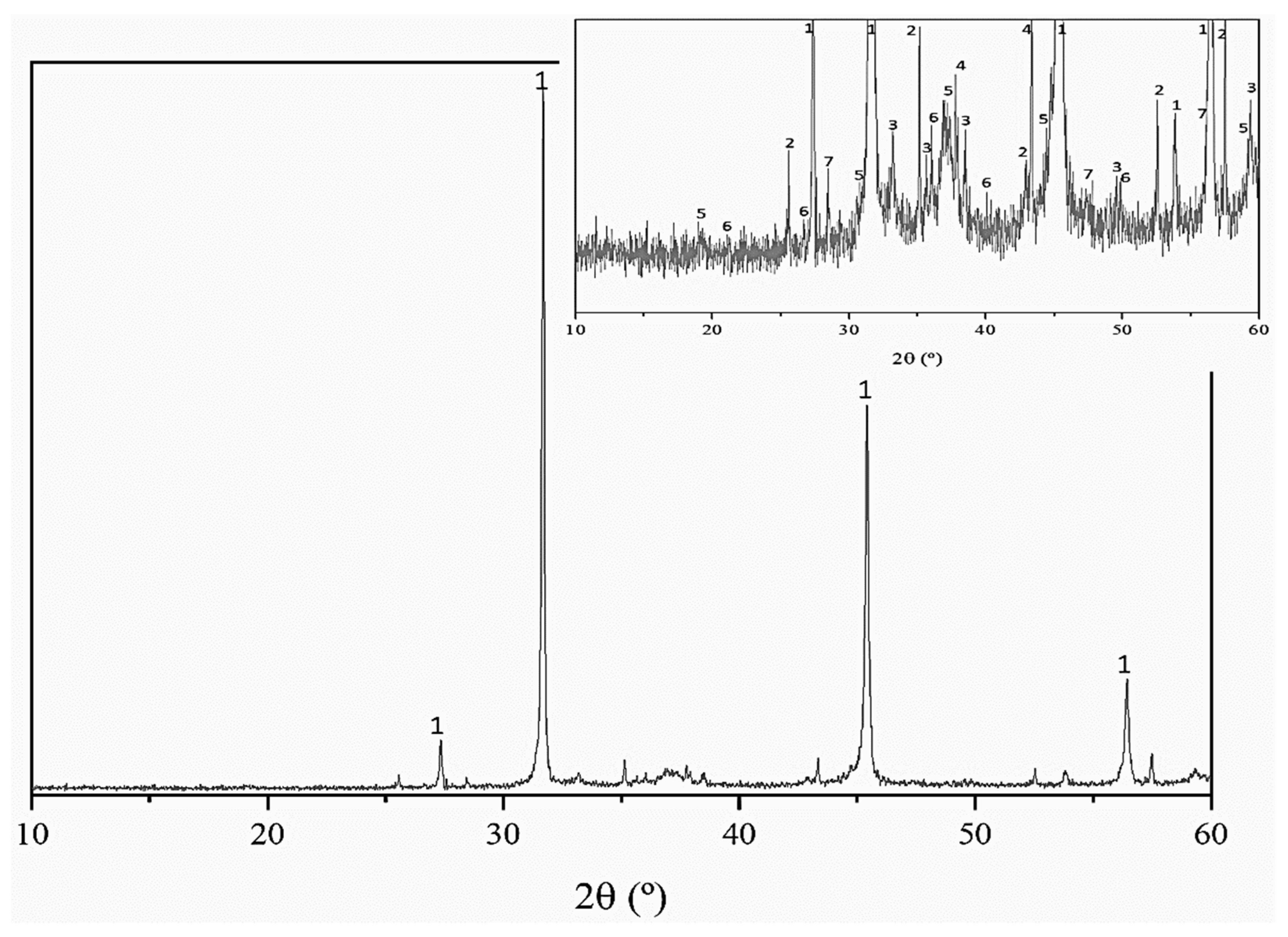
3.1. Hydrolysis of Salt Slag and Characterization of Products

The macroscopic appearances of the hydrolyzed slag after filtration (wet and dry) are shown in Figure 3a,b, respectively. Visual observation indicated a decrease in the grain size in the hydrolyzed salt in relation to the initial salt slag (Figure 1a).
The results of the hydrolysis tests are collected in Table 2, which includes the experimental conditions of the tests performed, the values of pH, density and ionic conductivity (I.C.) of the filtrates (brine) and the percentage recovery of NaCl and ammonia gas. Ammonia is generated by the reaction between the AlN content in the slag and water according to Equation (1).
2AlN + 3H2O → Al2O3 + 2NH3
The percentage of recovered NH3 was calculated taking into consideration that, according to the AlN content in the salt slag, a maximum of 30.40 Nm3 of gas can be recovered per ton of salt slag.
As expected, the values of the ionic conductivity of the brine obtained for the salt slag/water ratio of 1/3 were much higher than those corresponding to the 1/10 ratio due to the higher concentration of the solution, and, accordingly, the density values were due to the major concentration of salt.
The chemical composition of the brines obtained from hydrolyses 1/10-T25 and 1/3-T90 is collected in Table 3. The content of Na was almost three times the amount of brine obtained at a salt slag/water ratio of 1/3, but other significant elements, such as Al, were not affected by the dilution or temperature. In contrast, the Ca content was higher for the lowest salt slag/water ratio (1/10), probably due to the dissolution of any calcium carbonate included in the initial salt slag.
To recover the salt, the brine was subjected to a process of evaporation/crystallization. For the two temperatures tested, the recovery of NaCl was higher at a 1/10 ratio than at a 1/3 ratio due to the major volume of diluent (see Table 2). The chemical composition of a sample of salt obtained by evaporation/crystallization of brine 1/10-T25 is shown in Table 4.
Concerning NH3 (see Table 2), the gas was not recovered when tests were performed at room temperature. This may indicate that the hydrolysis of AlN did not occur to a large extent at this temperature or that, at room temperature, the effective stripping of the gases is not achieved.
According to the results obtained from the hydrolysis of the salt slag, although the test performed at a salt slag/water ratio of 1/10 allowed the major recovery of NaCl, the large volume of water that must be evaporated during the salt crystallization could make the process economically unviable. On the other hand, the higher the temperature of hydrolysis is, the higher the ammonia recovery. Thus, the best conditions for the hydrolysis of salt slag could be salt slag/water ratios of 1/3 and 90 °C.
The chemical composition of the hydrolyzed slag is shown in Table 5. Elements with values ≤0.1, such as K, Cr, Sr and Pb, were not included. The Al2O3 values ranged between 62 and 67%, being slightly higher in the tests carried out at room temperature, for the same S/L ratio, which indicates a lower loss of Al by dissolution.
The Cl (or Na) content was higher in the samples obtained in the tests with a higher S/L ratio. It should be taken into account that the cakes were not washed, so part of the salt content corresponds to the brine retained in the solid during filtration.

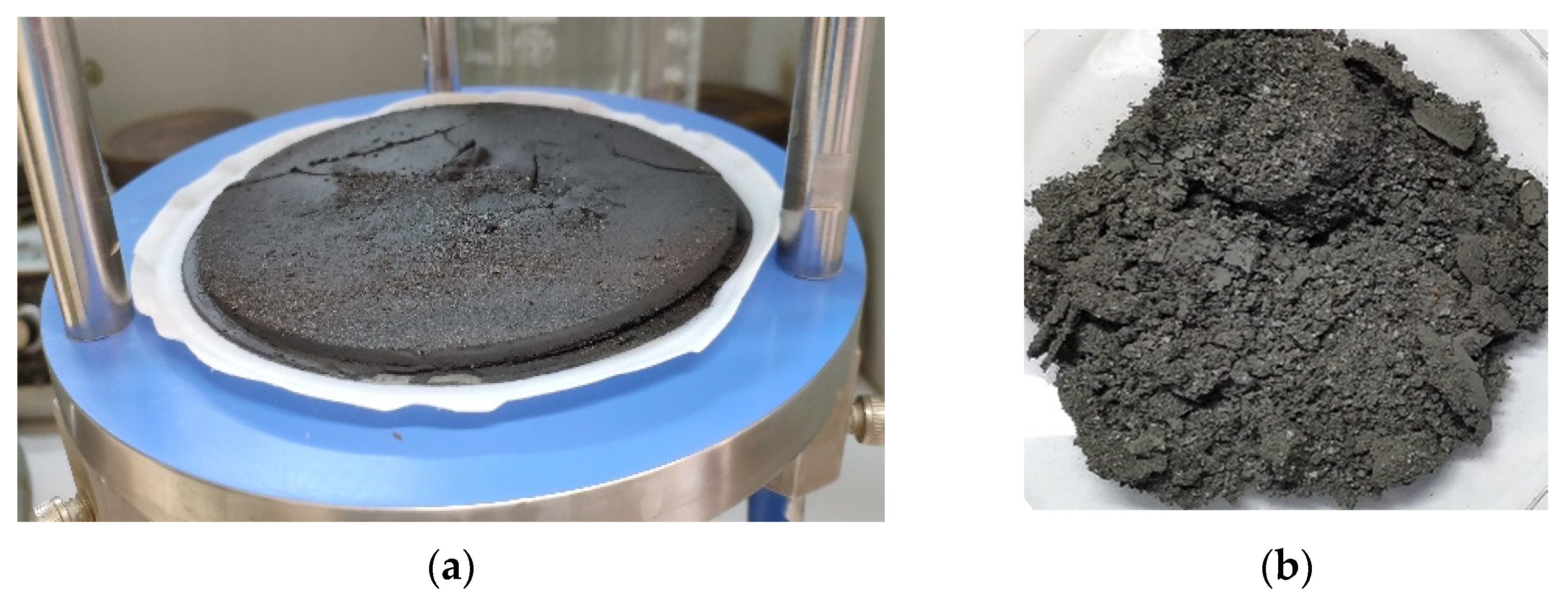
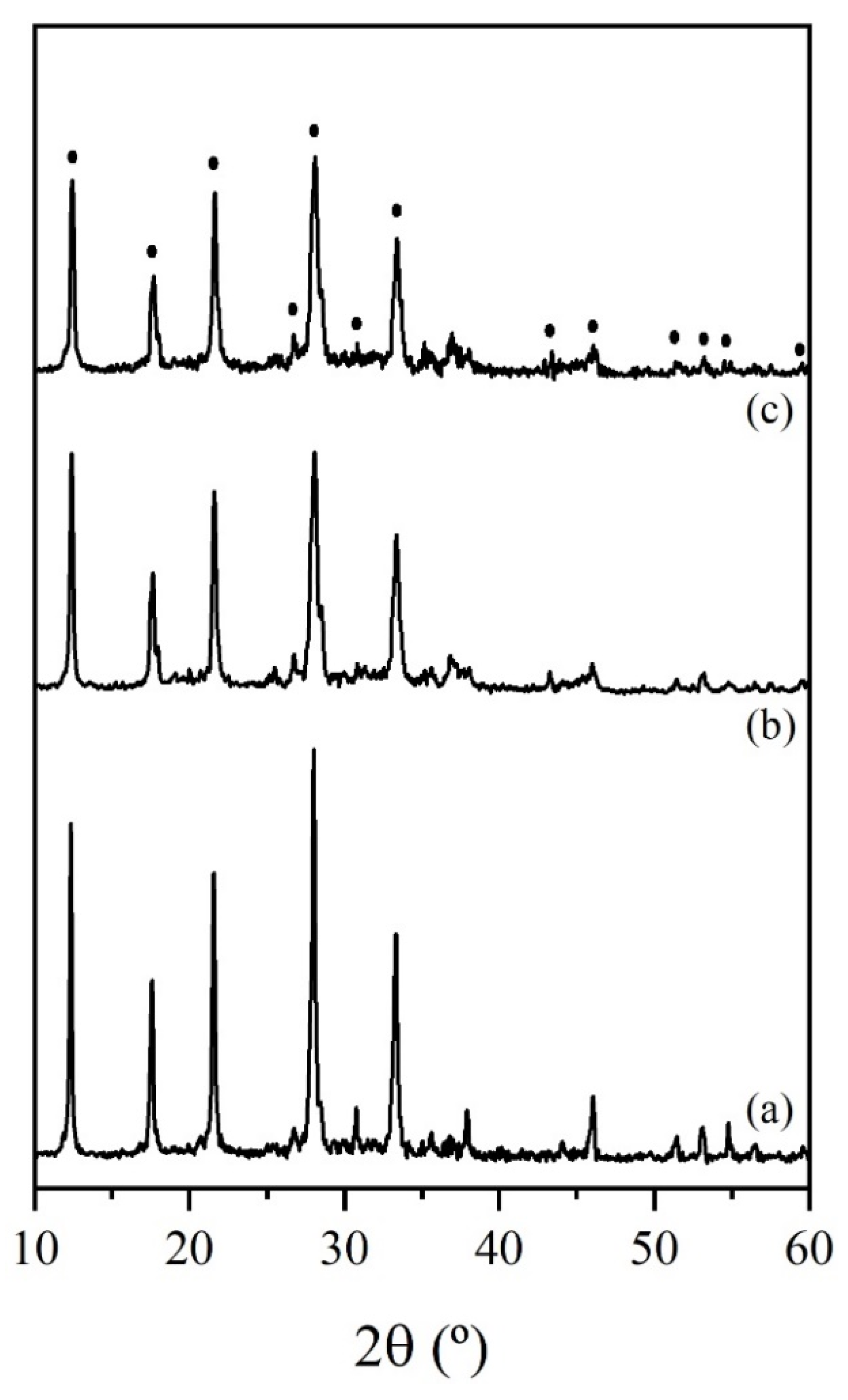
3.2. Synthesis of Zeolite

The synthesis of the zeolite was carried out using hydrolyzed slags 1/10-T25 and 1/3-T90. Table 6 lists the synthesis conditions and the results obtained, which include the reaction yield (expressed as mass of zeolite obtained per mass of the hydrolyzed slag used in the synthesis process) and the characteristics of the mother liquor (filtrate from the synthesis process), such as pH, ionic conductivity and density.
The pH, conductivity and density values of the mother liquors were quite similar for the three synthesis experiments carried out. The mass of the zeolite obtained was almost twice the mass of the hydrolyzed slag used in the synthesis due to the high molecular weight of the zeolite. A slightly higher yield was obtained for the reaction performed at 120 °C for 5 h, because the temperature favored the dissolution of aluminum oxide content in the hydrolyzed slag.
When the hydrolyzed slag used in the synthesis of zeolite comes from a hydrolysis process carried out at room temperature, ammonia gas is generated during the synthesis, and thus, in these experiments, 80–90% of ammonia was recovered. This indicates that ammonia can be recovered in the hydrolysis process or in the synthesis process, depending on the temperature used in the first process.
The XRD patterns of the samples are shown in Figure 4. All samples exhibited a profile characteristic of zeolite-type P (NaP, Na6Al6Si10O32.12H2O, cubic). Weak peaks attributable to spinel and quartz could be tentatively assigned. A slight splitting of the diffraction peaks corresponding to NaP zeolite was observed, principally for samples Z1/10-100-24h and Z1/10-120-5h, which could be due to, according to Taylor and Roy [44], the presence of the tetragonal phase of zeolite P (Na5,7Al5,7Si10.3O32.12H2O). NaP zeolites present variable compositions, with Si/Al ratios ranging between 1.59 and 2.63, and exhibit different symmetries (cubic, tetragonal or orthorhombic) depending on the synthesis conditions [44,45,46]. The crystallinity of the samples was higher for zeolite Z1/3-100-24h than for the other two zeolites. This seems to indicate that the use of hydrolyzed slag obtained at a high temperature (90 °C) leads to a more crystalline zeolite than those obtained from low-temperature hydrolyzed slag. This can be attributed to the presence or absence of AlN during the synthesis of zeolite: if the hydrolysis of salt slag is performed at room temperature, AlN is not hydrolyzed in this step; accordingly, hydrolysis and, consequently, ammonia gas release occur in the zeolite synthesis process.
The morphology of sample Z1/3-100-24h at different magnifications is shown in Figure 5a–d. At low magnification, the morphology consisted of “cauliflower-like” primary aggregates. At high magnification, these aggregates were formed by smaller secondary aggregates consisting of well-defined edges and anisotropic growth. Although morphology is very dependent on the synthesis process [45], this morphology has been reported for NaP zeolites obtained from other aluminum wastes [40], fly ash [47] and chemical reagents [48], among others.
The textural properties of the zeolite, such as the specific surface area (SBET), external surface (Sext), volume and pore size, were determined from the N2 adsorption/desorption isotherms (Figure 6a). As can be seen, the isotherms exhibit type IV behavior, which is typical of mesoporous materials such as zeolites. The small difference between SBET (17.00 m2 g−1) and Sex (16.88 m2 g−1) is related to the low micropore volume (8.4 × 10⁻⁵ cm3 g−1), which indicates that the sample was practically a non-microporous material. Ali et al. [49] reported SBET values ranging from 6 to 14 m2 g−1 for NaP zeolite obtained by chemical treatment at 100 °C for 4 days. Sánchez-Hernández et al. [40] reported values of ~14 m2 g−1 for zeolite obtained from a non-saline aluminum waste coming from slag milling. The curve of the pore size distribution obtained by the BJH method (Figure 6b) also shows a mesoporous distribution with a predominant pore size of 3.8 nm.
The NaP zeolite obtained from the salt slag exhibited a NH4Cl CEC value of 2.12 meq g−1, which is quite similar to the values reported in the literature for low Si/Al zeolites [36,49,50]. The variation in the zeta potential (Pz) with pH (Figure 7) shows that the surface of the zeolite was negatively charged under basic pH values. The initial value of Pz was −52 mV, which corresponds to a pH value of 9.2. Negative zeta potential values were maintained up to pH = 4.6, which is the isoelectric point. This parameter is related to the external surface charge, which depends on the SiO4/AlO4 ratio and plays an important role in adsorption processes. These findings confer to zeolite excellent characteristics to be used in processes related to removing metallic ions by cation exchange [51,52].

4. Conclusions

The results of this study allow us to conclude that a hazardous waste, such as salt slag produced in secondary aluminum metallurgy, can be valorized to produce zeolites in a straightforward process, which also allows salt and ammonia to be obtained as byproducts. Thus, for each ton of hydrolyzed slag, two tons of zeolite can be obtained. Moreover, more than 90% and 75% of salt and ammonia can be recovered as byproducts.
Although the work presented in this paper has been performed at laboratory scale, it has been conceptualized for a future scale-up. In this sense, some steps that could increase the cost of technology implementation have been avoided. For example, salt slag was used with the same granulometry as the one leaving the generating industry (there was no grinding or sieving process), and the hydrolyzed slag was not subjected to washing to remove remaining salt (the remaining NaCl content in the hydrolyzed slag did not affect the formation of zeolite). Nevertheless, future design and operation processes at pilot scale are under consideration.
Although the recovery of salt can be a costly process, the huge market for the commercialization of zeolite and the other byproducts can increase the benefits. Furthermore, the use of renewable energy such as solar energy for highly energy-demanding processes should be taken into account to reduce the energy cost.
Thus, this represents an important contribution to sustainability from both an environmental and economic point of view: the waste is removed from the usual hazardous waste management routes (saving costs and the enormous occupation of space) and is transformed into a raw material that can be used to obtain value-added materials.

Author Contributions

Conceptualization, A.L.-D. and I.P.; methodology, A.L.-D. and I.P.; investigation, I.P., M.R., S.L.-A. and A.L.-D.; writing—original draft preparation, I.P. and A.L.-D.; writing—review and editing, A.L.-D., M.R., S.L.-A. and I.P.; supervision, I.P., M.R. and A.L.-D.; funding acquisition, A.L.-D. and M.R. All authors have read and agreed to the published version of the manuscript.

Funding

This research was funded by Alusigma S.A., Sotiello, Gijón, Spain.

Institutional Review Board Statement

Not applicable.

Informed Consent Statement

Not applicable.

Data Availability Statement

Not applicable.

Acknowledgments

The authors thank Manuel Revuelta for technical advice. The technical support of Erick García and Unidad de Técnicas Geológicas-UCM is also recognized.

Conflicts of Interest

The authors declare no conflict of interest. The funders had no role in the design of the study; in the collection, analyses, or interpretation of data; in the writing of the manuscript; or in the decision to publish the results.

References

  1. Mahinroosta, M.; Allahverdi, A. Hazardous aluminum dross characterization and recycling strategies: A critical review. J. Environ. Manag. 2018, 223, 452–468. [Google Scholar] [CrossRef] [PubMed]
  2. López-Delgado, A.; Tayibi, H. Can hazardous waste become a raw material? the case study of an aluminium residue: A review. Waste Manag. Res. 2012, 30, 474–484. [Google Scholar] [CrossRef] [PubMed] [Green Version]
  3. Circular Aluminium Action Plan. A Strategy for Achieving Aluminium’s Full Potential for Circular Economy by 2030; Brussels, Belgium. 2020. Available online: https://european-aluminium.eu/media/2903/european-aluminium-circular-aluminium-action-plan.pdf (accessed on 2 February 2022).
  4. European Aluminium Vision 2050. European Aluminium’s Contribution to the EU’s Mid-Century Low-Carbon Roadmap; Brussels, Belgium. 2019. Available online: https://www.european-aluminium.eu/media/2545/sample_vision-2050-low-carbon-strategy_20190401.pdf (accessed on 8 February 2022).
  5. European Aluminium. European Aluminium & the Sustainable Development Goals. 2019. Available online: https://european-aluminium.eu/media/3253/european-aluminium_connecting-the-sustainability-roadmap-2025-to-the-sdgs-_december_2018_final.pdf (accessed on 10 February 2022).
  6. European Aluminium Recycling & Circular Economy. Available online: https://european-aluminium.eu/policy-areas/recycling-circular-economy/ (accessed on 10 February 2022).
  7. European Commission. Efficient Aluminium Salt Cake Recycling Technology. Available online: https://cordis.europa.eu/project/id/314922 (accessed on 15 January 2022).
  8. Tsakiridis, P.E. Aluminium salt slag characterization and utilization—A review. J. Hazard. Mater. 2012, 217–218, 1–10. [Google Scholar] [CrossRef] [PubMed]
  9. Gil, A.; Korili, S.A. Management and valorization of aluminum saline slags: Current status and future trends. Chem. Eng. J. 2016, 289, 74–84. [Google Scholar] [CrossRef]
  10. Tenorio, J.A.S.; Espinosa, D.C.R. Effect of salt/oxide interaction on the process of aluminum recycling. J. Light Met. 2002, 2, 89–93. [Google Scholar] [CrossRef]
  11. Ünlü, N.; Drouet, M.G. Comparison of salt-free aluminum dross treatment processes. Resour. Conserv. Recycl. 2002, 36, 61–72. [Google Scholar] [CrossRef]
  12. Zhang, L. State of the art in aluminum recycling from aluminum dross. TMS Light Met. 2006, 2006, 931–936. [Google Scholar]
  13. Bruckard, W.J.; Woodcock, J.T. Characterisation and treatment of Australian salt cakes by aqueous leaching. Miner. Eng. 2007, 20, 1376–1390. [Google Scholar] [CrossRef]
  14. Huang, X.L.; El Badawy, A.; Arambewela, M.; Ford, R.; Barlaz, M.; Tolaymat, T. Characterization of salt cake from secondary aluminum production. J. Hazard. Mater. 2014, 273, 192–199. [Google Scholar] [CrossRef]
  15. European Waste Catalogue and Hazardous Waste List, Published by the Environmental Protection Agency. Ireland. 2001. Available online: https://v4r7y5k5.stackpathcdn.com/wp-content/uploads/2016/08/EWC_HWL.pdf (accessed on 15 January 2022).
  16. European Commission. Commission Decision of 18 December 2014 Amending. Decision 2000/532/EC on the List of Waste Pursuant to Directive 2008/98/EC of the European Parliament and of the Council; Brussels, Belgium. 2014. Available online: https://eur-lex.europa.eu/legal-content/EN/TXT/?uri=celex%3A32014D0955 (accessed on 15 January 2022).
  17. Lysenko, A.P.; Sel’nitsyn, R.S.; Nalivaiko, A.Y. Comprehensive Processing of Saline Aluminum-Containing Slag. Metallurgist 2017, 61, 624–628. [Google Scholar] [CrossRef]
  18. Galindo, R.; Padilla, I.; Rodríguez, O.; Sánchez-Hernández, R.; López-Andrés, S.; López-Delgado, A. Characterization of Solid Wastes from Aluminum Tertiary Sector: The Current State of Spanish Industry. J. Miner. Mater. Charact. Eng. 2015, 3, 55–64. [Google Scholar] [CrossRef] [Green Version]
  19. David, E.; Kopac, J. The Assessment of the Recycling Process of Aluminum Hazardous Waste and a New Route of Development. Mater. Today Proc. 2019, 10, 340–347. [Google Scholar] [CrossRef]
  20. European Commission Efficient Aluminium Salt Cake Recycling Technology. In-House Salt Slag Processing Solution Which Turns Waste into a Product. 2022. Available online: https://cordis.europa.eu/article/id/223757-inhouse-salt-slag-processing-solution-which-turns-waste-into-a-product?msclkid=e4b28d11bf1411eca2aa783d8b270304 (accessed on 15 January 2022).
  21. Ballon, O. Aluminium Salt Slag Recycling: A Reality Check. In Proceedings of the Mineral Recycing Forum 2017, Rotterdam, The Netherlands, 7–8 March 2017. [Google Scholar]
  22. Wöhlk, W.; Niederjaufner, G.; Hofmann, G. Recycling of Cover Salt in the Secondary Aluminium Industry. Cryst. Precip. 1987, 99–108. [Google Scholar] [CrossRef]
  23. Graziano, D.; Hryn, J.N.; Daniels, E.J. The Economics of Salt Cake Recycling. United States. 1996. Available online: https://www.osti.gov/servlets/purl/224304 (accessed on 2 February 2022).
  24. Hazar, A.B.Y.; Saridede, M.N.; Çiǧdem, M. A study on the structural analysis of aluminium drosses and processing of industrial aluminium salty slags. Scand. J. Metall. 2005, 34, 213–219. [Google Scholar] [CrossRef]
  25. Davies, M.; Smith, P.; Bruckard, W.J.; Woodcock, J.T. Treatment of salt cakes by aqueous leaching and Bayer-type digestion. Miner. Eng. 2008, 21, 605–612. [Google Scholar] [CrossRef]
  26. Efficient Aluminium Salt Slag Recycling Technology: Significantly Reducing the Cost and CO2 Impacts of Transport for the Aluminium. 2017. Available online: https://cordis.europa.eu/article/id/223757-inhouse-salt-slag-processing-solution-which-turns-waste-into-a-product (accessed on 25 January 2022).
  27. Bruckard, W.J.; Woodcock, J.T. Recovery of valuable materials from aluminium salt cakes. Int. J. Miner. Process. 2009, 93, 1–5. [Google Scholar] [CrossRef]
  28. Xiao, Y.; Reuter, M.A.; Boin, U. Aluminium recycling and environmental issues of salt slag treatment. J. Environ. Sci. Health Part A Toxic/Hazardous Subst. Environ. Eng. 2005, 40, 1861–1875. [Google Scholar] [CrossRef]
  29. Peel, A.; Gibbs, A. Improvements in and Relating to Processing Methods and Processing Apparatus. WO Patent 2018/096358, 31 May 2018. Available online: https://patentscope.wipo.int/search/en/detail.jsf?docId=WO2018096358 (accessed on 20 January 2022).
  30. Momza, M.O.; Corsini, T.; Calende, S.; Fracchia, P. Process for the Processing of Slag from Aluminium Scrap and Waste Melting, Recovery of Components Thereof and Treatment of Gasses Generated. U.S. Patent 5013356, 7 May 1991. Available online: https://patents.google.com/patent/US5013356A/en (accessed on 15 January 2022).
  31. Peng, L.; Mei, Z.; Lidong, T.; Seetharaman, S. Recycling of Aluminum Salt Cake: Utilization of Evolved Ammonia. Metall. Mater. Trans. B 2013, 44, 16–19. [Google Scholar]
  32. Torres, J. Beneficios del Uso del PAVAL Para la Fabricación de Cementos. 2019. Available online: https://www.ieca.es/producto/beneficios-del-uso-del-paval-la-fabricacion-cementos/ (accessed on 15 January 2022).
  33. Torrez-Herrera, J.J.; Korili, S.A.; Gil, A. Bimetallic (Pt-Ni) La-hexaaluminate catalysts obtained from aluminum saline slags for the dry reforming of methane. Chem. Eng. J. 2022, 433, 133191. [Google Scholar] [CrossRef]
  34. Jiménez, A.; Misol, A.; Morato, Á.; Rives, V.; Vicente, M.A.; Gil, A. Optimization of hydrocalumite preparation under microwave irradiation for recovering aluminium from a saline slag. Appl. Clay Sci. 2021, 212, 106217. [Google Scholar] [CrossRef]
  35. Galindo, R.; López-Delgado, A.; Padilla, I.; Yates, M. Synthesis and characterisation of hydrotalcites produced by an aluminium hazardous waste: A comparison between the use of ammonia and the use of triethanolamine. Appl. Clay Sci. 2015, 115, 115–123. [Google Scholar] [CrossRef] [Green Version]
  36. Lobo-Recio, M.; Rodrigues, C.; Jeremias, T.; Lapolli, F.R.; Padilla, I.; López-Delgado, A. Highly efficient removal of aluminum, iron, and manganese ions using Linde type-A zeolite obtained from hazardous waste. Chemosphere 2021, 267, 128919. [Google Scholar] [CrossRef] [PubMed]
  37. Shi, B.; Chang, Q. Green synthesis of fly ash-based zeolite Y by mixed alkali fusion method. Micro Nano Lett. 2021, 16, 540–545. [Google Scholar] [CrossRef]
  38. Ren, X.; Qu, R.; Liu, S.; Zhao, H.; Wu, W.; Song, H.; Zheng, C.; Wu, X.; Gao, X. Synthesis of zeolites from coal fly ash for the removal of harmful gaseous pollutants: A review. Aerosol. Air Qual. Res. 2020, 20, 1127–1144. [Google Scholar] [CrossRef] [Green Version]
  39. López-Delgado, A.; Robla, J.I.; Padilla, I.; López-Andrés, S.; Romero, M. Zero-waste process for the transformation of a hazardous aluminum waste into a raw material to obtain zeolites. J. Clean. Prod. 2020, 255, 120178. [Google Scholar] [CrossRef]
  40. Sánchez-Hernández, R.; Padilla, I.; López-Andrés, S.; López-Delgado, A. Eco-friendly bench-scale zeolitization of an Al-containing waste into gismondine-type zeolite under effluent recycling. J. Clean. Prod. 2017, 161, 792–802. [Google Scholar] [CrossRef] [Green Version]
  41. Sánchez-Hernández, R.; López-Delgado, A.; Padilla, I.; Galindo, R.; López-Andrés, S. One-step synthesis of NaP1, SOD and ANA from a hazardous aluminum solid waste. Microporous Mesoporous Mater. 2016, 226, 267–277. [Google Scholar] [CrossRef]
  42. ASTM C 136—01 Standard Test Method for Sieve Analysis of Fine and Coarse Aggregates. Available online: https://www.studocu.com/en-us/document/colorado-school-of-mines/water-supply-engineering/astm-c136-2014-standard-test-method-for-sieve-analysis-of-fine-and-coarse-aggregates/8462887 (accessed on 4 December 2021).
  43. Wentworth, C.K. A scale of grade and class terms for clastic sediments. J. Geol. 1922, 27, 292–377. [Google Scholar] [CrossRef]
  44. Taylor, A.M.; Roy, R. Zeolite studies IV: Na-P zeolites and the ion-exchanged derivatives of tetragonal Na-P1. Am. Mineral. 1964, 49, 656–682. [Google Scholar]
  45. Huo, Z.; Xu, X.; Lü, Z.; Song, J.; He, M.; Li, Z.; Wang, Q.; Yan, L. Synthesis of zeolite NaP with controllable morphologies. Microporous Mesoporous Mater. 2012, 158, 137–140. [Google Scholar] [CrossRef]
  46. Azizi, D.; Ibsaine, F.; Dionne, J.; Coudert, L.; Blais, J. Microporous and macroporous materials state-of-the-art of the technologies in zeolitization of aluminosilicate bearing residues from mining and metallurgical industries: A comprehensive review. Microporous Mesoporous Mater. 2021, 318, 111029. [Google Scholar] [CrossRef]
  47. Qiu, X.; Liu, Y.; Li, D.; Yan, C. Preparation of NaP zeolite block from fly ash-based geoplymer via in situ hydrothermal method. J. Porous Matter 2015, 22, 291–299. [Google Scholar] [CrossRef]
  48. Ali, I.O.; El-Sheikh, S.M.; Salama, T.M.; Bakr, M.F.; Fodial, M.H. Controllable synthesis of NaP zeolite and its application in calcium adsorption. Sci. China Mater 2015, 58, 621–623. [Google Scholar] [CrossRef] [Green Version]
  49. Vistuba, J.P.; Nagel-Hassemer, M.E.; Lapolli, F.R.; Lobo-Recio, M.Á. Simultaneous adsorption of iron and manganese from aqueous solutions employing an adsorbent coal. Environ. Technol. 2013, 34, 275–282. [Google Scholar] [CrossRef]
  50. Espejel-Ayala, F.; Schouwenaars, R.; Durán-Moreno, A.; Ramírez-Zamora, R.M. Use of drinking water sludge in the production process of zeolites. Res. Chem. Intermed. 2014, 40, 2919–2928. [Google Scholar] [CrossRef]
  51. Gillies, G.; Raj, R.; Kopinke, F.; Georgi, A. Suspension stability and mobility of Trap-Ox Fe-zeolites for in-situ nanoremediation. J. Colloid Interface Sci. 2017, 501, 311–320. [Google Scholar] [CrossRef]
  52. Sánchez-Hernández, R.; Padilla, I.; López-Andrés, S.; López-Delgado, A. Single and competitive adsorptive removal of lead, cadmium, and mercury using zeolite adsorbent prepared from industrial aluminum waste. Desalin. WATER Treat. 2018, 126, 181–195. [Google Scholar] [CrossRef] [Green Version]
Figure 1. Macroscopic appearance of the salt slag (a) and granulometry (b).
Sustainability 14 04887 g001
Figure 2. XRD pattern of the salt slag (1 = halite (NaCl, pdf 77-2064), 2 = corundum (Al2O3, pdf 46-1212), 3 = AlN, pdf 65-0831, 4 = Al, pdf 04-0787, 5 = spinel (MgAl2O4, pdf 021-1152), 6 = quartz (SiO2, pdf 83-0539), 7= Si, pdf 027-1402).
Sustainability 14 04887 g002
Figure 3. Hydrolyzed slag: (a) wet and (b) dry.
Sustainability 14 04887 g003
Figure 4. DRX pattern of zeolite obtained under the different experimental conditions studied: (a) Z1/3-100-24h; (b) Z1/10-100-24h and (c) Z1/10-120-5h (dots indicate the XRD reflections of NaP zeolite).
Sustainability 14 04887 g004
Figure 5. SEM images of zeolite at different magnifications obtained from salt slag: (a) ×1·103; (b) ×1·104; (c) ×2.5·104; (d) ×6·104.
Sustainability 14 04887 g005
Figure 6. Nitrogen adsorption/desorption isotherms (a) and distribution of pore diameter (b) of zeolite obtained from salt slag.
Sustainability 14 04887 g006
Figure 7. Variation in the zeta potential of the zeolite obtained from salt slag with the pH in aqueous suspension.
Sustainability 14 04887 g007
Table 1. Chemical composition of the salt slag (FRX, expressed as wt.% oxide, except Cl).
Al2O3SiO2ClNa2OMgOFe2O3CaOSO3K2OTiO2Cr2O3MnOP2O5CuOZnOBaO
30.72.727.630.83.71.11.30.20.20.40.10.10.10.30.30.2
Table 2. Experimental conditions of hydrolysis of salt slag and results.
Hydrolysis TestsT
(°C)
Ratio
Slag/Water
Filtrate (Brine)Recovered NaCl
(%)
Recovered
NH3
(%)
pHI. C.
(mS cm−1)
Density
(g L−1)
1/10-T25251/1010.0 ± 0.164 ± 41.03 ± 0.0196n.r.
1/3-T25251/39.9 ± 0.1159 ± 21.09 ± 0.0189n.r.
1/10-T90901/1010.4 ± 0.168 ± 31.03 ± 0.019877
1/3-T90901/39.6 ± 0.1168 ± 11.09 ± 0.018088
n.r. = not recovered.
Table 3. Semiquantitative chemical composition of brine (ICP–OES, in µg mL−1).
BrineNaKAlCaSiSPSrBaLiZnMo Cu Cr Pb Mg Mn Ti Ni Co
1/10-T2512,88532442116181416190.4<0.2<0.2
1/3-T9039,61764035181547n.d.n.d.4<0.21<0.2
Elements with concentration ≤0.1 are not included; n.d. = not determined.
Table 4. Chemical composition of salt from hydrolysis test 1/10-T25 (FRX, expressed as wt.% oxide, with the exception of Cl).
ClNa2OAl2O3SiO2Fe2O3CaOSO3K2OBrSrO
55.143.30.50.10.030.50.10.50.020.01
Table 5. Chemical composition of the hydrolyzed slag (FRX, expressed as wt.% oxide, with the exception of Cl).
Hydrolyzed SlagAl2O3SiO2ClNa2OMgOFe2O3CaOSO3TiO2MnOCuOZnOBaO
1/10-T2567.44.02.82.57.82.31.70.40.80.30.80.70.3
1/3-T2565.33.43.53.38.12.01.80.40.70.30.70.60.4
1/10-T9065.36.11.91.87.03.12.40.51.10.31.00.80.5
1/3-T9062.15.37.37.46.52.51.90.30.70.20.70.50.3
Table 6. Experimental conditions for the synthesis of zeolite from hydrolyzed slag and mother liquor characteristics.
Hydrolyzed SLAGZeoliteExperimental ConditionsYield
mZeol (g)/mHS (g)
Mother Liquor
T (°C)t (h)pHI.C.
(mS cm−1)
Density
(g L−1)
1/10-T25Z1/10-120-5h12051.912.8 ± 0.1145 ± 21.03 ± 0.01
Z1/10-100-24h100241.812.9 ± 0.1144 ± 21.04 ± 0.01
1/3-T90Z1/3-100-24h100241.812.8 ± 0.1147 ± 21.04 ± 0.01
Publisher’s Note: MDPI stays neutral with regard to jurisdictional claims in published maps and institutional affiliations.

