Abstract
An increased electricity demand and dynamic load changes are creating a huge burden on the modern utility grid, thereby affecting supply reliability and quality. It is thus crucial for modern power system researchers to focus on these aspects to reduce grid outages. High-quality power is always desired to run various businesses smoothly, but power-electronic-converter-based renewable energy integrated into the utility grid is the major source of power quality issues. Many solutions are constantly being invented, yet a continuous effort and new optimized solutions are encouraged to address these issues by adhering to various global standards (IEC, IEEE, EN, etc.). This paper therefore proposes a concept of establishing a renewable-energy-based microgrid cluster by integrating various buildings located in an urban community. This enhances power supply reliability by managing the available energy in the cluster without depending on the utility grid. Further, a “fuzzy space vector pulse width modulation” (FSV-PWM) technique is proposed to control the inverter, which improves the power supply quality. This work uniquely optimized the dq reference currents using fuzzy logic theory, which were used to plot the space vectors with effective sector selection to generate accurate PWM signals for inverter control. The modeling/simulation of the microgrid cluster involving the FSV-PWM-based inverter was carried out using MATLAB/Simulink®. The efficacy of the proposed FSV-PWM over the conventional ST-PWM was verified by plotting voltage, frequency, real/reactive power, and harmonic distortion characteristics. Various power quality indices were calculated under different disturbance conditions. The results showed that the use of the proposed FSV-PWM-based inverter adhered to all the key standard requirements, while the conventional system failed in most of the indices.
1. Introduction
The electricity demand of any country is a reflection of its economic growth. The increasing quality of life worldwide has led to more sophisticated energy demands. The world’s urban population is expected to increase from 55% (4.2 billion) to 69% (6.7 billion) of the 9.7 billion people on the planet by 2050, which will result in huge consumption of existing energy sources [1,2]. It will accordingly be critical to meet the worldwide consumer load demand with the desired quality of power supply. Thus, the topic of power quality is considered to be a significant perspective based on the current position of renewable energy resources and the frequent connection of these resources to distribution systems [3]. Thus, work on distributed-generation-based microgrids has been ongoing for several years. Initially, microgrids were introduced to deliver the power to the areas where there is less accessibility to conventional power. In such places, the microgrids are installed to work in both autonomous and grid-connected modes. The aggregation of low-power sources in a microgrid or virtual power plant is the actual direction of boosting the efficiency of distributed generation and renewable energy resources. These systems have numerous characteristics including a huge number of semiconductor devices, the stochastic nature of renewable generation, and bi-directional power flow. As a result, ensuring the required power quality indicators such as voltage fluctuations, frequency deviation, non-sinusoidality, and overall harmonic distortions is a critical responsibility [4,5].
For the past few years, researchers have developed various optimization techniques, filters, controllers, FACTS devices, compensators, and battery storage units to address the power quality concerns of the microgrids. These studies are primarily focused on three aspects: (1) inverter topologies controlled by modern modulation techniques, (2) alternative conversion methods to replace power electronic inverters, and (3) taking uncertainty into account when designing storage units for energy management. A review of these literature works on improving the power quality of distribution power systems is presented as follows.
The adaption-based control strategy is proposed to improve the power quality parameters at the point of common coupling (PCC) of a three-phase distribution system. The control strategy is designed to balance three-phase currents and compensate for the reactive power of the system [6]. Microgrid power quality is managed using a model predictive control methodology, which regulates the microgrid’s power converters to meet the requirements. The control algorithm is designed to function with the microgrid when it is connected to the utility grid mode, or in standalone mode, or in interconnected mode [7]. Different control strategies for improving the quality of power in a microgrid at the distribution side are discussed in [8]. Moreover, in [9], the authors presented a comprehensive survey of power quality enhancement devices, with a focus on the auxiliary services provided by multi-functional generators. A review of the microgrid concept, testbeds, and related control approaches was also conducted. Later in [10], in the presence of a shunt active power filter (SAPF), the impact of power quality difficulties in an adopted standalone microgrid system (comprising solar, wind, and fuel-cell-based distributed generation) is explored. In the realization of this SAPF, a traditional synchronous reference frame and modified synchronous reference frame techniques are used for reference current generation, proportional–integral controller and fuzzy logic controller are used for DC-link capacitor voltage regulation, and a basic hysteresis band current controller technique is used for inverter switching pulse generation. Similarly, in [11], the authors proposed a decision-making approach for determining the power quality of a single-phase AC microgrid along with the development of a power quality monitoring index to evaluate the fuzziness in a random variation of power quality. Further, the authors in [12] proposed an upgraded custom power device termed a “distributed power condition controller” to improve the power quality in a multi-microgrid system with a high penetration of varied distributed generators in the island and interconnected modes. An improved triple-action controller design as a combination of a proportional–resonant controller, selective harmonic compensator (SHC), and feed-forward current controller is proposed [13]. This work examines a standalone distributed generating inverter’s controller, where the SHC produces a continuous sinusoidal voltage.
For a multilevel converter, an optimal current control mechanism is proposed [14]. In online harmonic compensation applications in microgrids, the control approach will overcome the inefficiencies of earlier control methods in harmonic current tracking. Grid-connected inverter-based multi-functional distributed generation converters can use this control mechanism. Later in [15], the authors tried to solve the fixed-frequency operation and fast dynamics problems by proposing a unique robust voltage control technique using an angle droop scheme. The voltage controller is designed with rotating reference frames in mind to reduce the detrimental effects of harmonics and negative-sequence disruption generated by nonlinear and unbalanced loads. The negative consequences of parameter variation, model uncertainty, and unmodeled dynamics are calculated in the required form and employed as a constraint in the optimization problem to increase the overall system’s robustness. An adaptive droop controller based on a fuzzy logic method is proposed in [16]. The droop coefficient is adaptively modified to lessen the influence of the line impedance and achieve appropriate power splitting among hybrid energy by detecting unbalanced power and voltage deviation. Further, a small-signal model was created to investigate the impact of droop coefficient modification on DC microgrid stability. In the work reported in [17], self-tuning filters along with fuzzy logic were used to extract the harmonic currents for controlling the DC voltage required for a multilevel inverter. Similarly, D-Statcom was modeled and controlled with the use of fuzzy and PI current controllers for voltage quality improvement [18].
A brief review was given of the FACTS technologies used for stabilization and power filtering in distribution systems [19]. Along with custom power devices, some different evolutionary algorithms are also proposed for improved power quality [20]. In [21], a robust, quick, and dynamic proportional–integral resonance controller with a harmonic and lead compensator feedback (PIR + HC + LC) is presented to manage the current of a 15-level neutral-point-clamped multilevel inverter. In [22], a unified power quality conditioner proposed as a standardized power quality conditioner for a nine-level structure is investigated. A solar system and a smart grid are both connected to the conditioner. For the switches of both series and parallel converters, a novel modulation technique to generate switching signals is discussed. This modulation technique uses an adaptive hysteresis band calculated by a fuzzy logic controller to produce the appropriate adjusted output voltage with minimal distortion.
The above literature addresses the power quality issues in a single microgrid that is operated in either autonomous or grid-connected mode, and all these methods are limited for multi-microgrid systems. Moreover, most of these methods have not considered all the typical characteristics of the power quality issue. A steady evolution of regulations on how the energy is to be generated and used demands the continuous exploration of new and effective solutions. Hence, in view of all these points, this paper,
- Proposes the concept of establishing a renewable-energy-based microgrid cluster by integrating multiple adjacent microgrids located in an urban community. This enhances power supply reliability by managing the available energy in the cluster without depending on the utility grid. An energy management system (EMS) is designed to manage the available energy in the cluster, which helps to reduce the dependency on the central utility grid.
- Proposes a “fuzzy space vector pulse width modulation” (FSV-PWM) technique to control the inverter, which improves the power supply quality. The use of the proposed fuzzy logic increases the capabilities of the control loop in regulating the system output under different operating conditions.
2. Microgrid Cluster and Its Constituents
The general architecture of the microgrid cluster system considered for the study is shown in Figure 1. It is formed by interconnecting four different buildings, viz. residential, software industry, academic institute, and manufacturing industry buildings, with different load profiles and is completely based on the AC power park. Each building is referred to as a single microgrid and is associated with locally available sources such as photovoltaic (PV), wind units (WTs), and fuel cells (FCs) along with storage batteries, AC/DC converters (rectifiers), DC/DC converters, and DC/AC inverters for local building loads. The modeling of all constituents is discussed in brief [23,24,25,26]. Each microgrid is linked to renewable sources in combination with paid sources and a storage system and DC/DC converters along with building loads. The voltage produced from the renewable sources is very low, so the voltage is increased to the value of 500 V (DC) which is the equivalent to an AC voltage of 415 V. Before being connected to neighboring microgrids or the utility grid, each microgrid in the cluster is equipped with a circuit breaker, which is controlled by the control signals provided by the EMS. The EMS manages the power flow by controlling and monitoring the entire process of each building in the microgrid cluster. It is connected to all of the individual buildings and the utility grid. The EMS generates a control signal based on the power excess/deficit situations and delivers it to the circuit breaker for switching ON/OFF, resulting in energy transfer. All individual energy resources in each building are connected to their own DC bus and then connected to a DC/AC converter, which powers a variety of loads. Table 1 shows the details of the generation and load profiles of the proposed microgrid cluster. The information about all the typical parameters used for modeling the cluster is mentioned in Appendix A. The integration of more distributed generations, storage systems, and necessary loads makes microgrid operation more difficult, especially when microgrids are networked and interoperable. Figure 2 shows the EMS operations developed to share the power among the neighbor microgrids connected in the cluster in island/grid-connected conditions [26].
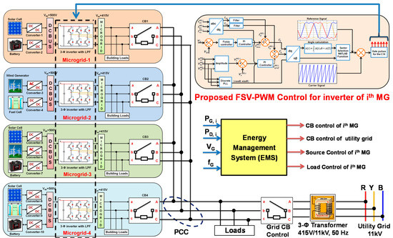
Figure 1.
Elucidation of microgrid cluster as an integrated multi-microgrid system.

Table 1.
Generation and load profile of the microgrid cluster.
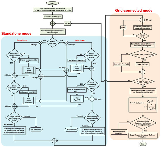
Figure 2.
Flow of EMS operations in microgrid cluster.
3. Description of the Proposed Control Strategy
When compared to sinusoidal pulse-width modulation, space-vector pulse-width modulation has become one of the most common PWM approaches due to its quicker digital implementation and greater DC bus utilization. The block diagram representation of the control circuit for producing switching gate pulses applied to the inverter of an ith microgrid is shown in Figure 3. It consists of two stages: (1) fuzzy-logic-based abc-dq0 transformation for calculation of Iref and (2) switching states and switching times of the current source inverter (CSI) of ith microgrid. The sequence of steps to produce switching pulses from the proposed control strategy to the inverter is shown in Figure 4.
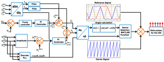
Figure 3.
Block diagram representation of control circuit for operating inverter of the ith microgrid.
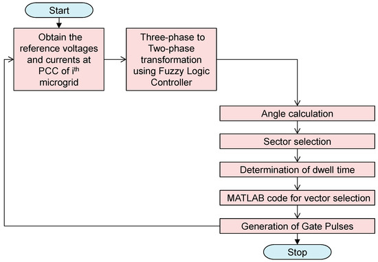
Figure 4.
Flowchart representation of FSV-PWM for generating gate pulses to the ith microgrid.
3.1. Calculation Reference Current (Iref) Using Fuzzy Logic
The set of voltages and currents are transformed to the frame using Equations (1) and (2) [10].
Here, and are the source currents and voltages with respect to the frame, and , are the source currents and voltages with respect to the frame. The transformation of the frame to the frame is given in Equation (3). The reference current with respect to the d-axis () is obtained as given in Equation (4), where is the d-axis current, and the loss component value at sampling instant () for meeting the losses in the ith microgrid is obtained as given in Equation (5).
where are PI controller gains and are tuned by fuzzy logic rules. Similarly, the reference current with respect to q-axis () is obtained as given in Equation (6).
Here, is the q-axis current and is the output component produced by the PI controller. The magnitude of the terminal voltage of the ith microgrid at PCC is calculated as given in Equations (7) and (8).
where is the q-axis current at the instant and is the terminal voltage amplitude at the sampling instant, where are PI controller gains. The reference current can be obtained as given in Equation (9). The reference current vector can be obtained as given in Equation (10).
The fuzzy controller of the proposed inverter is implemented by considering and evaluating some linguistic rules. The fuzzy controller consists of two inputs and one output function, the input error value is calculated by taking the difference between the reference voltage (V*dc) and sensed voltage (Vdc).
Here, both input signals, i.e., and , are numerical variables, which are transformed into linguistic variables. The fuzzy controller surface plot is shown in Figure 5. The proposed fuzzy scheme is characterized by the following features or assumptions.
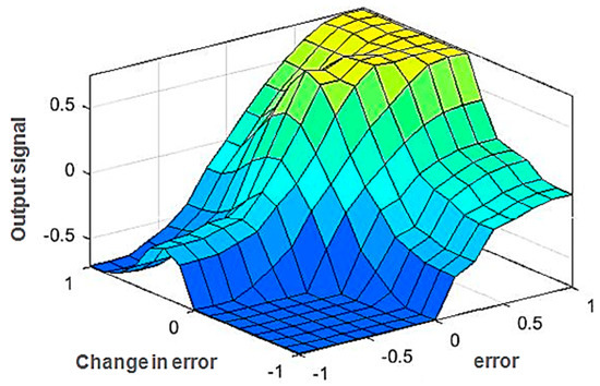
Figure 5.
Surface plot of the fuzzy controller.
- (1)
- Consists of seven fuzzy sets, namely, negative big (NB−3), negative medium (NM−2), negative small (NS−1), extreme zero (EZ0), positive small (PS+1.), positive medium (PM+2), and positive big (PB+3),
- (2)
- Triangular membership function with the Mamdani inference mechanism is used.
- (3)
- Centroid method is used for defuzzification.
- (4)
- A fuzzy logic controller is designed by considering 49 rules as listed in Table 2.
Table 2. Rules proposed for the implementation of the fuzzy logic.
3.2. Determination of Switching State and Switching Times
The switching limitation for CSI [27,28] space vector PWM is that only two switches should be active at any given moment. One is from the CSI’s top commutation group, while the other is from the bottom commutation group. The switching time duration of any sector from 1 to 6 of the inverter is shown in Table 3 for the space phasor diagram of the CSI shown in Figure 6.
Table 3.
Switching time duration of all sectors.
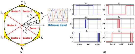
Figure 6.
(a) Space phasor diagram (b) switching gate pulses for CSI.
The mathematical expression for the active vector of the CSI space vector is given by Equation (11), where ‘n’ is the sector number of the current vector position,
The time that space vectors spend in a sector during is represented by the dwell time for stationary vectors. The so-called ampere-second balance principle is the foundation for dwell-time estimates. The key principle is that the total of the current vectors multiplied by the time interval of chosen space vectors equals the product of the sampling period and the reference vector , and it can be assumed to be constant throughout time if is small enough.
The reference current is approximated using this concept by using the nearby vectors corresponding to the real sector and the zero vectors to adjust the length. The ampere-second balance principle is given by Equations (12) and (13) to calculate and .
From Figure 6a, the reference current vector is projected onto the real and imaginary axis, and we get Equations (14) and (15). Upon solving Equations (12)–(15), Equation (16) can be obtained.
Here,, , and are dwell times of the phasors , , , and is the modulation index. By using Equation (11), we can determine the individual space vectors in sector 1. The generalized equation of the space vector in sector 1 is calculated as given in Equation (16). The typical value of space vector pulse width modulation is in the range [0.577–0.637], which is an improvement on the sinusoidal-PWM value range [0.5–0.577].
4. Results and Discussion
The usefulness of the proposed fuzzy space vector pulse width modulation (FSV-PWM)-based inverter for urban community microgrid cluster application was analyzed by considering parameters related to power quality, viz. voltage swell/sag [29,30], voltage imbalance [31,32], frequency deviations [33,34], power characteristics [35], and total harmonic distortion [35,36] with respect to various standard requirements. All these are explained in the following subsections. Various test conditions implemented to conduct the proposed study are presented in Table 4.
Table 4.
Test conditions and procedures for power quality study.
4.1. Analysis of Voltage Characteristics
The voltage waveform shape is to be maintained as pure sinusoidal, otherwise the distorted waveform leads to unequal voltage distribution in the cluster system. The main reason for the voltage sag is an abrupt change in the current flowing through the impedance (source), and sudden application of load or faults draws a high quantity of source currents, thus reducing the voltage. In the case of a voltage swell, sudden removal of load leads to less source current being drawn and causes an increase in the voltage. Typical voltage characteristics such as voltage sag/swell and imbalance are measured by considering test conditions given in Table 4. Test cases from 1(a) to 1(d) were considered and executed to observe the voltage sag, voltage swell, and voltage imbalance characteristics. The results obtained using simulations are shown in Figure 7, Figure 8, Figure 9 and Figure 10. The quantitative values are consolidated and presented in Table 5.
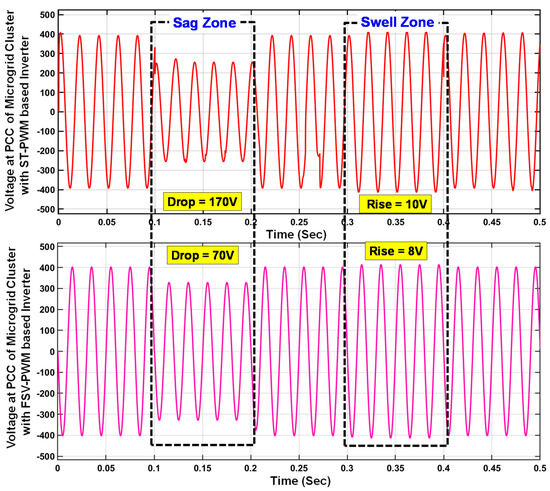
Figure 7.
Comparison of voltage sag/swells of microgrid cluster with conventional ST-PWM and proposed FSV-PWM-based inverters as per test cases 1(a) and 1(c).
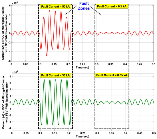
Figure 8.
Comparison of currents during voltage sag/swells of microgrid cluster with conventional ST-PWM and proposed FSV-PWM-based inverters as per test cases 1(a) and 1(c).
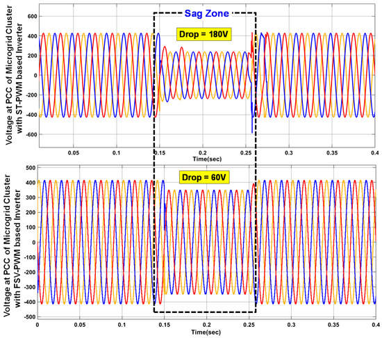
Figure 9.
Comparison of voltage sag of microgrid cluster with conventional ST-PWM and proposed FSV-PWM-based inverters as per test case 1(b).
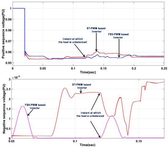
Figure 10.
Comparison of voltage imbalances of microgrid cluster with conventional ST-PWM and proposed FSV-PWM-based inverters as per test case 1(d).
Table 5.
Comparison of power quality indices with conventional and proposed methods.
A comparison of voltage sag/swells of microgrid cluster with conventional ST-PWM and proposed FSV-PWM-based inverters as per test cases 1(a) and 1(c) is given in Figure 7. From this, it is observed that the voltage sag (drop) in the conventional system is 170 volts, while it is 70 volts in the proposed system. Similarly, the voltage swell (rise) in the conventional system is 10 volts, while it is 8 volts in the proposed system. Hence, both the sag and swell are reduced with the use of the proposed FSV-PWM-based inverter. Similarly, the current waveforms during the voltage sag and swells as per test cases 1(a) and 1(c) are shown in Figure 8. From the obtained results it is shown that when a line to ground fault is applied in phase ‘a’, the fault current is higher, i.e., 50 kA as in the case of the ST-PWM-based inverter used in the cluster, which is high when compared with the proposed inverter which gives 35 kA. A comparison of voltage sag of the microgrid cluster with conventional ST-PWM and proposed FSV-PWM-based inverters as per test case 1(b) is given in Figure 9. From this, it is observed that the voltage sag (drop) in the conventional system is 180 volts, while it is 60 volts in the proposed system. Hence, this test condition also suggests the importance of the proposed method to address the voltage sag issue.
Similarly, a comparison of voltage imbalance of the microgrid cluster with conventional ST-PWM and proposed FSV-PWM-based inverters as per test case 1(d) is given in Figure 10. The positive sequence voltage and negative sequence voltages are plotted. From this, it is observed that the conventional system produces more deviation, thereby creating an imbalance in the voltage characteristic compared to the proposed method. The imbalance issue is solved using the proposed FSV-PWM-based inverter.
4.2. Analysis of Frequency Characteristics
Frequency is the important parameter that is to be continuously monitored and controlled when the microgrid is either operated in grid-connected or autonomous mode. For analyzing the frequency characteristics of the proposed system, different test cases 2(a) and 2(b) from Table 4 were considered and executed. The simulated results are shown in Figure 11 and the consolidated quantitative results are listed in Table 5.
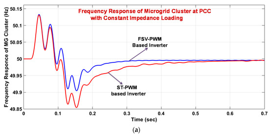
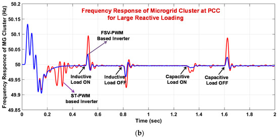
Figure 11.
Comparison of frequency characteristics of microgrid cluster with conventional ST-PWM and proposed FSV-PWM-based inverters as per test cases 2(a) and 2(b). (a) Frequency response as per test case 2(a). (b) Frequency response as per test case 2(b).
4.3. Analysis of Power Characteristics
The real and reactive power changes in the microgrid cluster are observed by injecting an inductive load of 100 kVAR from 0.1 to 0.2 s and a capacitive load of 75 kVAR from 0.3 to 0.4 s along with the baseload of 275 kW + j50 kVAR, as defined by test case 3 in Table 4. The corresponding simulation results are as shown in Figure 12; from which it is observed that the transient variations are smaller in the case of the proposed FSV-PWM-based inverter when compared to the conventional ST-PWM-based inverter during the applied large reactive load disturbances. These consolidated quantitative results are listed in Table 5.
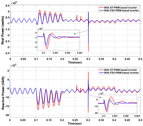
Figure 12.
Comparison of power characteristics of microgrid cluster with conventional ST-PWM and proposed FSV-PWM-based inverters as per test case 3.
4.4. Analysis of Total Harmonic Distortion
Total harmonic distortion is due to the nonlinear/high reactive loads in the microgrid cluster. For analyzing these distortions, consider the test cases 4(a) and 4(b) from Table 4 which are simulated as per the given procedure. The corresponding simulated results are shown in Figure 13. The consolidated results are listed in Table 5.
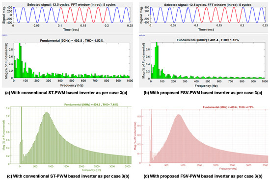
Figure 13.
Comparison of harmonic distortion characteristic of microgrid cluster with conventional ST-PWM and proposed FSV-PWM-based inverters as per test cases 4(a) and 4(b).
5. Conclusions
With the rising prevalence of renewable energy sources in power distribution systems, power electronic inverters are becoming increasingly crucial. Due to the rising importance to urbanization, microgrids are interconnected and run to provide stable, high-quality power to the consumers as well as to the grid. Thus, by considering factors such as the growing requirement for grid-independent systems, clean energy generation, and reliable and quality supply to feed consumer equipment, this paper proposes the concept of establishing renewable-energy-based microgrid clusters by integrating multiple adjacent microgrids located in an urban community. Further, to control the inverter, a “fuzzy space vector pulse width modulation” (FSV-PWM) technique is proposed. The salient advantages of this proposed system over the conventional system are as follows.
- The interoperable cluster microgrids can enhance the power supply reliability by managing the available energy in the cluster without depending on the utility grid. This further helps to reduce the dependency on the central utility grid, thereby solving the issue of frequent grid outages. However, the operation of an energy management system plays a crucial role in achieving effective energy sharing.
- Improved power quality through the proposed FSV-PWM technique by increasing the capabilities of the control loop in regulating the system output under different operating conditions. This can protect the power system during different critical uncertain conditions, such as large resistive/reactive loads, faults, arcing loads.
- Simple construction and reduced usage of clamping diodes and capacitors.
- Reduced stress with a low rating of the switching devices.
- The use of fuzzy logic reduces the usage of mathematical formulations.
- The modulation index is high.
- Reduced current harmonics when compared to the conventional mechanism.
Hence, from the comprehensive results obtained on various power quality indices, it is concluded that the proposed FSV-PWM controlled inverter is the best option to improve the power quality in urban community cluster microgrids.
Author Contributions
Data curation, C.P.R.; Formal analysis, S.N.V.B.R. and D.J.P.; Funding acquisition, A.F., H.K. and J.F.A.-A.; Investigation, S.N.V.B.R.; Methodology, Y.V.P.K.; Project administration, Y.V.P.K.; Resources, A.F., H.K. and J.F.A.-A.; Software, C.P.R.; Supervision, Y.V.P.K.; Validation, D.J.P.; Visualization, C.P.R. and H.K.; Writing—original draft, S.N.V.B.R.; Writing—review and editing, Y.V.P.K. and A.F. All authors have read and agreed to the published version of the manuscript.
Funding
This research was funded by the Ministry of Education in Saudi Arabia under grant number IF_2020_NBU_417 and by the Science and Engineering Research Board (SERB) in India under grant number SRG/2019/000648.
Institutional Review Board Statement
Not applicable.
Informed Consent Statement
Not applicable.
Data Availability Statement
Not applicable.
Acknowledgments
The authors extend their appreciation to the Deputyship for Research & Innovation, Ministry of Education in Saudi Arabia, for funding this research work through the project number IF_2020_NBU_417. The authors gratefully thank the Prince Faisal bin Khalid bin Sultan Research Chair in Renewable Energy Studies and Applications (PFCRE) at Northern Border University for their support and assistance. The authors also thank the Start-up Research Grant (SRG) scheme of the Science and Engineering Research Board (SERB), a statutory body under the Department of Science and Technology (DST), Government of India, for supporting this work under project number SRG/2019/000648.
Conflicts of Interest
The authors declare no conflict of interest.
Appendix A
The typical parameters used for modeling the microgrid cluster are as follows.
| Parameter | Typical Ratings |
| Solar Cell | |
| Open circuit voltage | 41 volts |
| Short circuit current | 3.16 amp |
| Irradiance | [150–1000] kW/m2 |
| Temperature | [20–45] °C |
| Electric charge | 1.6 × 10⁻¹⁹ coulombs |
| Boltzmann’s constant | 1.3805 × 10⁻²³ J/K |
| Energy gap | 1.1 eV |
| Wind Turbine | |
| Base power of wind | (1000/0.9) VA |
| Speed of wind | 10 m/s |
| Rotational speed of wind | 1.2 PU |
| Rotor efficiency (high speed with 2 blades) | 0.45 |
| Battery | |
| Nominal voltage of battery | 88 volts |
| Rated capacity of battery | 6.5 Ah |
| Initial SOC of battery | 100% |
| Response time of battery | 30 s |
| Fuel Cell | |
| Stack temperature of fuel cell | 343 K |
| Faraday’s constant of fuel cell | 96,484,600 |
| Gas constant of fuel cell | 8314.7 |
| Output voltage of fuel cell | 0.8 volts |
| No. of cells in stack of fuel cell | 80 |
| Utilization factor of fuel cell | 0.8 |
| H2/O2 flow ratio of fuel cell | 1.168 |
| DC/DC Converter | |
| Duty cycle | 0.76 |
| Inductance | 200 μH |
| Capacitance | 10 μF |
| Initial capacitor voltage | 200 volts |
| Switching frequency | 100 kHz |
| Cutoff frequency of low pass filter | 500 Hz |
| Damping factor of low pass filter | 0.707 |
| Transmission line length | 10 km |
| Distribution Transformer | |
| Power | 300 kVA |
| Frequency | 50 Hz |
| Winding-1: RMS voltage (phase–phase) | 420 volts |
| Resistance | 0.016 Ω |
| Winding-2: RMS voltage (phase–phase) | 420 volts |
| Resistance | 0.016 Ω |
| Utility Grid | |
| Grid voltage | 11,000 volts |
| Grid frequency | 50 Hz |
| Source resistance | 0.8929 Ω |
| Source inductance | 16.58 mH |
References
- Ana Jane, B.; André Felipe, S. Assessing the urban sustainable development strategy: An application of a smart city services sustainability taxonomy. Ecol. Indic. 2021, 127, 107734. [Google Scholar] [CrossRef]
- Bramareswara Rao, S.N.V.; Padma, K. A Review on Schemes for Interconnecting Microgrids of Urban Buildings. In Microelectronics, Electromagnetics and Telecommunications; Chowdary, P.S.R., Chakravarthy, V.V.S.S.S., Anguera, J., Satapathy, S.C., Bhateja, V., Eds.; Lecture Notes in Electrical Engineering; Springer: Singapore, 2021; Volume 655, pp. 431–438. ISBN 9789811538278. [Google Scholar] [CrossRef]
- Kakran, S.; Chanana, S. Smart Operations of Smart Grids Integrated with Distributed Generation: A Review. Renew. Sustain. Energy Rev. 2018, 81, 524–535. [Google Scholar] [CrossRef]
- Shalukho, A.V.; Lipuzhin, I.A.; Voroshilov, A.A. Power Quality in Microgrids with Distributed Generation. In Proceedings of the 2019 International Ural Conference on Electrical Power Engineering (UralCon), Chelyabinsk, Russia, 1–3 October 2019; pp. 54–58. [Google Scholar] [CrossRef]
- Kumar, R.; Bansal, H.O. Shunt Active Power Filter: Current Status of Control Techniques and Its Integration to Renewable Energy Sources. Sustain. Cities Soc. 2018, 42, 574–592. [Google Scholar] [CrossRef]
- Momeni, M.; Mazinan, A.H. Improvement of power quality in grid-connected inverter through adaptation-based control strategy. Energy Ecol. Environ. 2019, 4, 37–48. [Google Scholar] [CrossRef]
- Garcia-Torres, F.; Vazquez, S.; Gil-de-Castro, A.; Roncero-Sanchez, P.; Moreno-Munoz, A. Microgrids Power Quality Enhancement Using Model Predictive Control. Electronics 2021, 10, 328. [Google Scholar] [CrossRef]
- Viswanathan, L.; Kumar, S. A Review: Control Strategies for Power Quality Improvement in Microgrid. Int. J. Renew. Energy Res. 2018, 8, 150–165. [Google Scholar] [CrossRef]
- Naderi, Y.; Hosseini, S.H.; Zadeh, S.G.; Mohammadi-Ivatloo, B.; Vasquez, J.C.; Guerrero, J.M. An overview of power quality enhancement techniques applied to distributed generation in electrical distribution networks. Renew. Sustain. Energy Rev. 2018, 93, 201–214. [Google Scholar] [CrossRef]
- Barik, P.K.; Shankar, G.; Sahoo, P.K. Power quality assessment of microgrid using fuzzy controller aided modified SRF based designed SAPF. Int. Trans. Electr. Energy Syst. 2020, 30, e12289. [Google Scholar] [CrossRef]
- Kaushal, J.; Basak, P. A Novel Approach for Determination of Power Quality Monitoring Index of an AC Microgrid Using Fuzzy Inference System. Iran. J. Sci. Technol. Trans. Electr. Energy 2018, 42, 429–450. [Google Scholar] [CrossRef]
- Esmaeili, M.; Shayeghi, H.; Valipour, K.; Safari, A.; Sedaghati, F. Power quality improvement of multi-microgrid using improved custom power device called as distributed power condition controller. Int. Trans. Electr. Energy Syst. 2020, 30, e12259. [Google Scholar] [CrossRef]
- Naderi, Y.; Hosseini, S.H.; Zadeh, S.G.; Mohammadi-Ivatloo, B.; Savaghebi, M.; Guerrero, J.M. An optimized direct control method applied to multilevel inverter for microgrid power quality enhancement. Int. J. Electr. Power Energy Syst. 2019, 107, 496–506. [Google Scholar] [CrossRef]
- Salem, A.E.; Salim, O.N.; Arafa, S.I. New triple-action controller for inverter power quality improvement. Comput. Electr. Eng. 2020, 81, 106543. [Google Scholar] [CrossRef]
- Haiya, Q.; Xu, Q.; Jun, Z.; Yuan, X. A robust GPS-based control scheme for power sharing and quality improvement in microgrid. Int. J. Electr. Power Energy Syst. 2020, 123, 106324. [Google Scholar] [CrossRef]
- Ni, F.; Yan, L.; Liu, J.; Shi, M.; Zhou, J.; Chen, X. Fuzzy logic-based virtual capacitor adaptive control for multiple HESSs in a DC microgrid system. Int. J. Electr. Power Energy Syst. 2019, 107, 78–88. [Google Scholar] [CrossRef]
- Zellouma, L.; Rabhi, B.; Saad, S.; Benaissa, A.; Benkhoris, M.F. Fuzzy Logic Controller of Five Levels Active Power Filter. Energy Procedia 2015, 74, 1015–1025. [Google Scholar] [CrossRef]
- Amoozegar, D. Dstatcom Modelling for Voltage Stability with Fuzzy Logic PI Current Controller. Int. J. Electr. Power Energy Syst. 2016, 76, 129–135. [Google Scholar] [CrossRef]
- Gandoman, F.H.; Ahmadi, A.; Sharaf, A.M.; Siano, P.; Pou, J.; Hredzak, B.; Agelidis, V.G. Review of FACTS Technologies and Applications for Power Quality in Smart Grids with Renewable Energy Systems. Renew. Sustain. Energy Rev. 2018, 82, 502–514. [Google Scholar] [CrossRef]
- Mosaad, M.I.; Ramadan, H.S. Power Quality Enhancement of Grid-Connected Fuel Cell Using Evolutionary Computing Techniques. Int. J. Hydrog. Energy 2018, 43, 11568–11582. [Google Scholar] [CrossRef]
- Jahan, S.; Biswas, S.P.; Hosain, M.K.; Islam, M.R.; Haq, S.; Kouzani, A.Z.; Mahmud, M.A.P. An Advanced Control Technique for Power Quality Improvement of Grid-Tied Multilevel Inverter. Sustainability 2021, 13, 505. [Google Scholar] [CrossRef]
- Kenjrawy, H.; Makdisie, C.; Houssamo, I.; Mohammed, N. New Modulation Technique in Smart Grid Interfaced Multilevel UPQC-PV Controlled via Fuzzy Logic Controller. Electronics 2022, 11, 919. [Google Scholar] [CrossRef]
- Venkatramanan, D.; John, V. Dynamic Modeling and Analysis of Buck Converter Based Solar PV Charge Controller for Improved MPPT Performance. IEEE Trans. Ind. Appl. 2019, 55, 6234–6246. [Google Scholar] [CrossRef]
- Rao, S.N.V.B.; Kumar, Y.V.P.; Padma, K. Implementation of Minigrid with Hybrid Renewable Energy Sources for Urban Community Buildings. Int. J. Renew. Energy Res. 2019, 8, 10882–10892. [Google Scholar] [CrossRef]
- Farrokhabadi, M.; Konig, S.; Canizares, C.A.; Bhattacharya, K.; Leibfried, T. Battery Energy Storage System Models for Microgrid Stability Analysis and Dynamic Simulation. IEEE Trans. Power Syst. 2018, 33, 2301–2312. [Google Scholar] [CrossRef]
- Rao, S.N.V.B.; Padma, K. Control of Grid Frequency under Unscheduled Load Variations: A Two Layer Energy Management Controller in Urban Green Buildings. Int. J. Renew. Energy Res. 2020, 10, 1951–1961. [Google Scholar] [CrossRef]
- Neukirchner, L.; Magyar, A. Modelling a Three-Phase Current Source Inverter. Hung. J. Ind. Chem. 2016, 44, 105–111. [Google Scholar] [CrossRef][Green Version]
- Ding, L.; Li, Y. Control of Power Electronic Converters and Systems; Academic Press: Cambridge, MA, USA, 2021; pp. 367–402. [Google Scholar] [CrossRef]
- IEEE SA. IEEE 141-1993. Available online: https://standards.ieee.org/ieee/141/312/ (accessed on 12 March 2022).
- IEC Webstore. IEC 61000-4-11: 2020. Available online: https://webstore.iec.ch/publication/63503 (accessed on 12 March 2022).
- IEEE Std 1159.3-2019 (Revision of IEEE Std 1159.3-2003); IEEE Recommended Practice for Power Quality Data Interchange Format (PQDIF). IEEE: New York, NY, USA, 2019; pp. 1–185. [CrossRef]
- Pavan Kumar, Y.V.; Bhimasingu, R. Electrical Machines Based DC/AC Energy Conversion Schemes for the Improvement of Power Quality and Resiliency in Renewable Energy Microgrids. Int. J. Electr. Power Energy Syst. 2017, 90, 10–26. [Google Scholar] [CrossRef]
- IEC Webstore. IEC 61727: 2004. Available online: https://webstore.iec.ch/publication/5736 (accessed on 12 March 2022).
- IEC Webstore. IEC 61000-2-2: 2002. Available online: https://webstore.iec.ch/publication/4133 (accessed on 12 March 2022).
- IEEE Std 1547.1-2020; IEEE Standard Conformance Test Procedures for Equipment Interconnecting Distributed Energy Resources with Electric Power Systems and Associated Interfaces. IEEE: New York, NY, USA, 2020; pp. 1–282. [CrossRef]
- IEEE Std 519-2014 (Revision of IEEE Std 519-1992); IEEE Recommended Practice and Requirements for Harmonic Control in Electric Power Systems. IEEE: New York, NY, USA, 2014; pp. 1–29. [CrossRef]
Publisher’s Note: MDPI stays neutral with regard to jurisdictional claims in published maps and institutional affiliations. |
© 2022 by the authors. Licensee MDPI, Basel, Switzerland. This article is an open access article distributed under the terms and conditions of the Creative Commons Attribution (CC BY) license (https://creativecommons.org/licenses/by/4.0/).