
Construction Solutions and Materials to Optimize the Energy Performances of EPS-RC Precast Bearing Walls


Abstract
:1. Introduction
2. State-of-the-Art
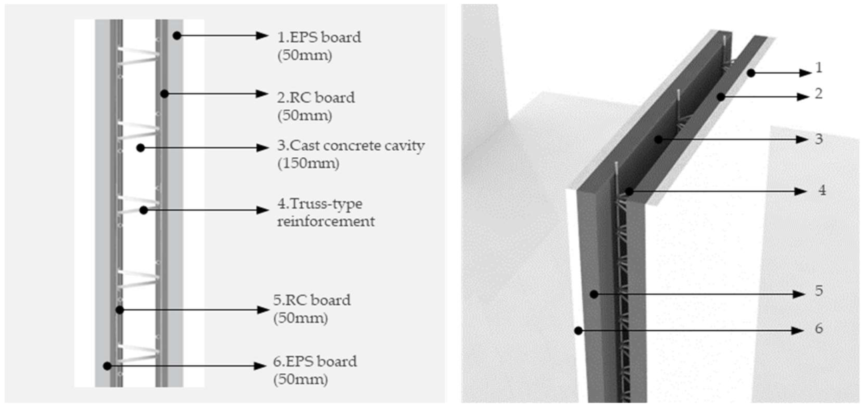
- Precast concrete sandwich panels (PCSPs), which are composite cladding types encompassing concrete wythes that embed a layer of thermal insulation. They are fully fabricated in the factory, thus ensuring greater quality control and a reduced risk of poor detailing, in addition to further performances including fire resistance, durability and thermal insulation [11,12,13,14];
3. Materials and Methods
3.1. Background
3.2. Research Development
4. Results
4.1. Employment of Recycled EPS in Concrete Mixtures
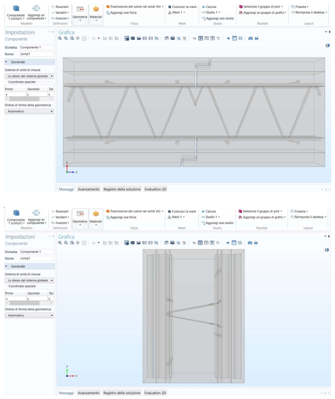
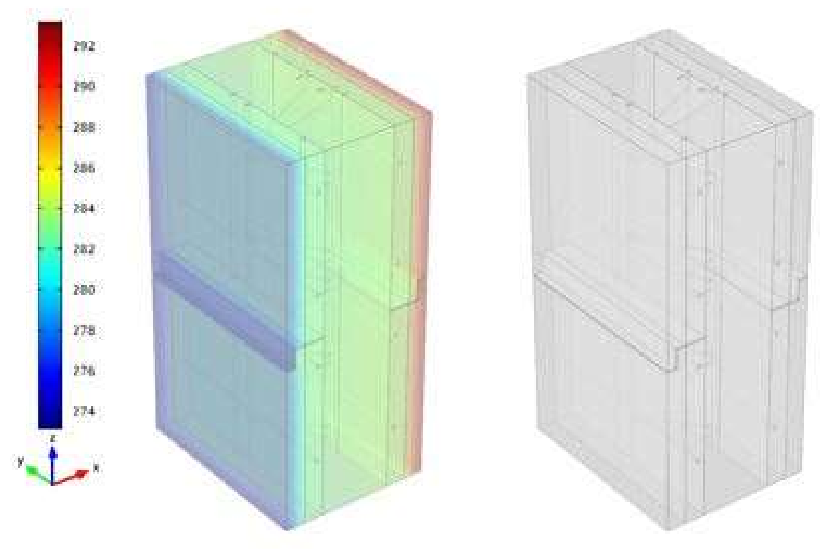
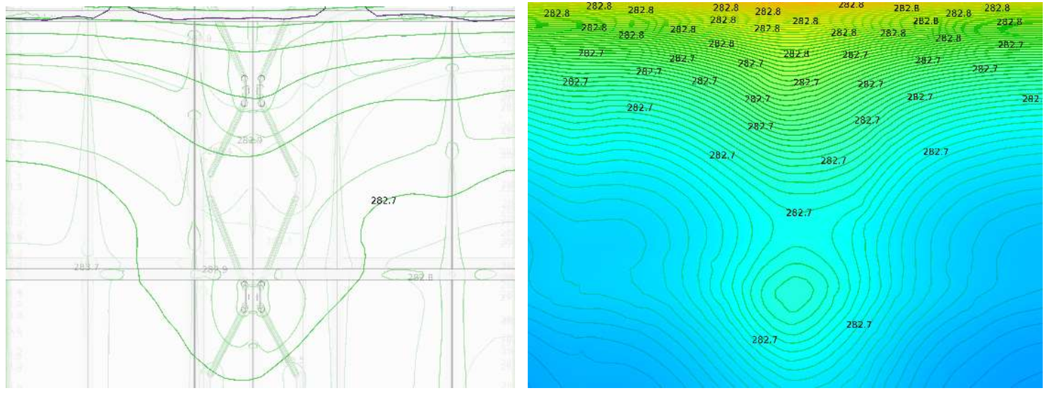
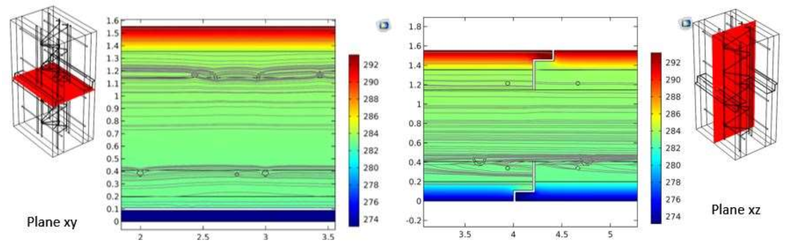
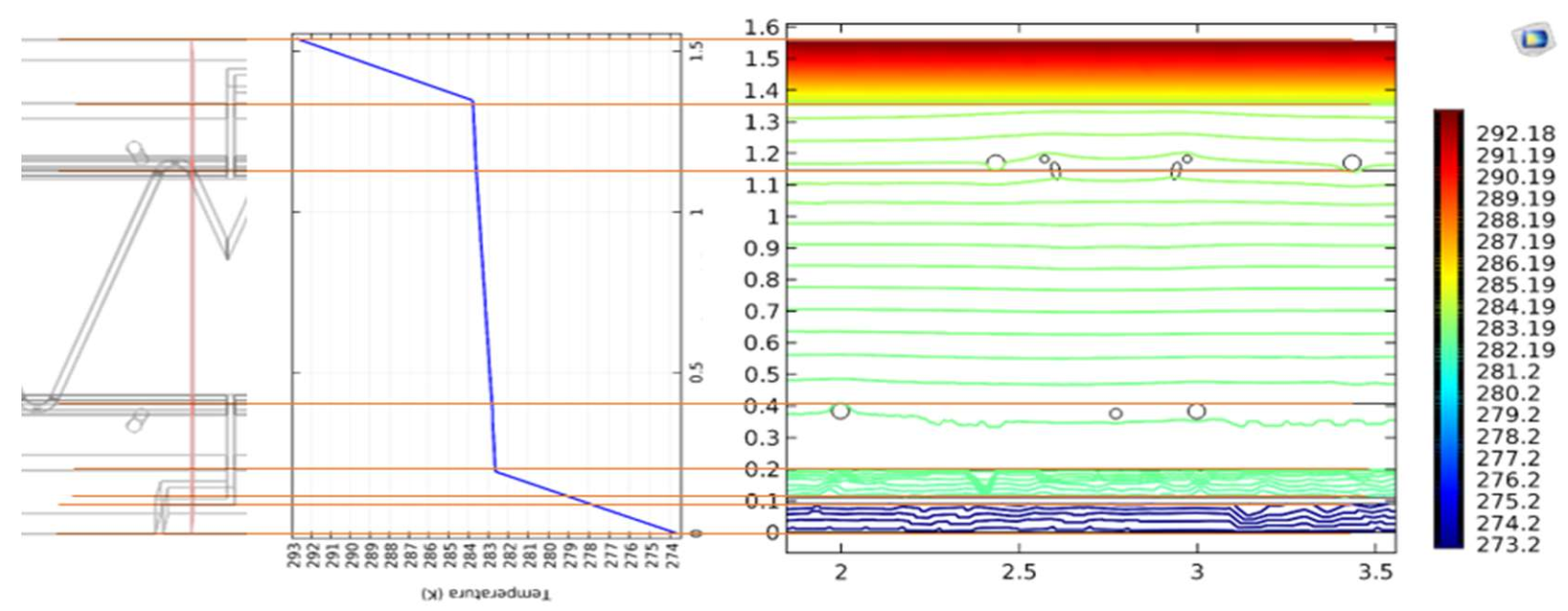
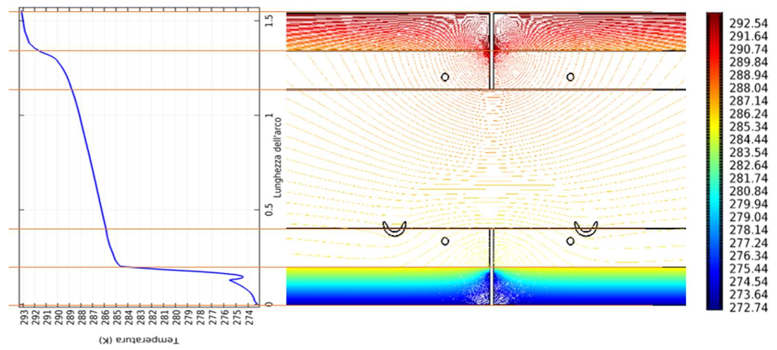
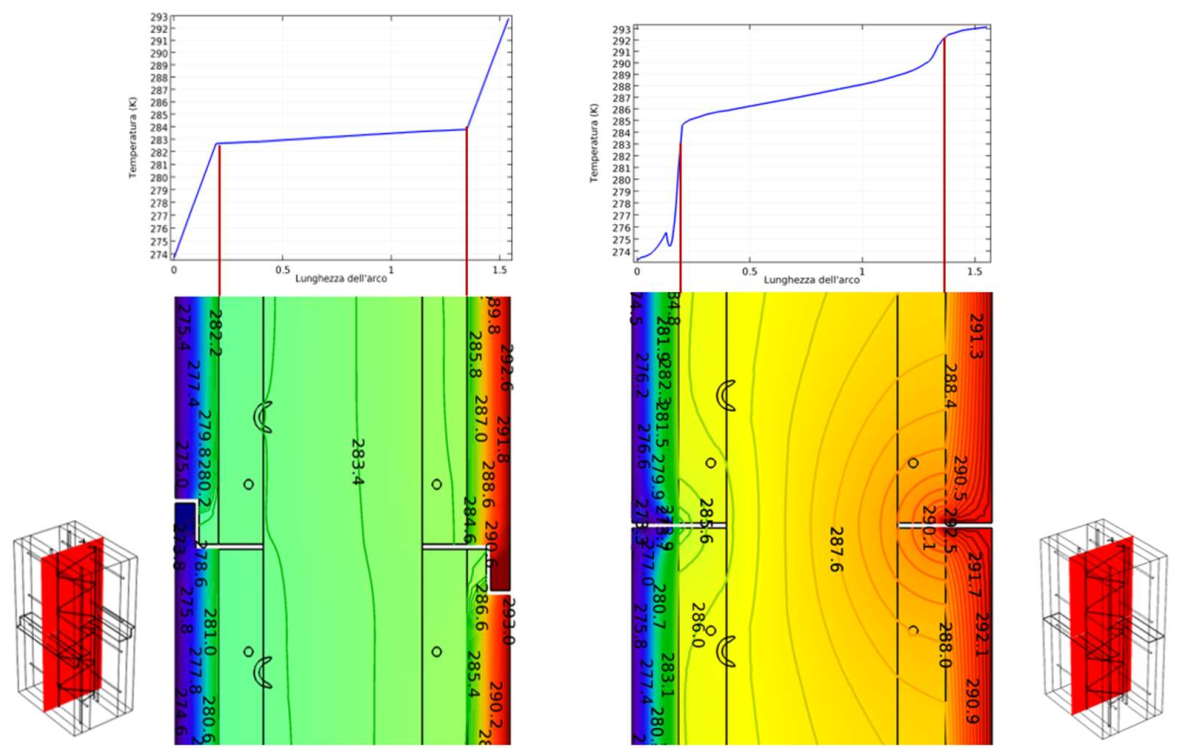
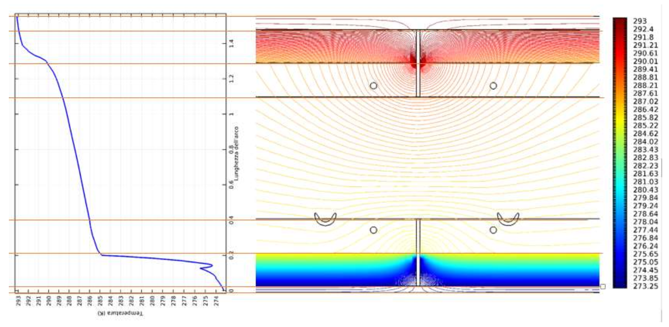
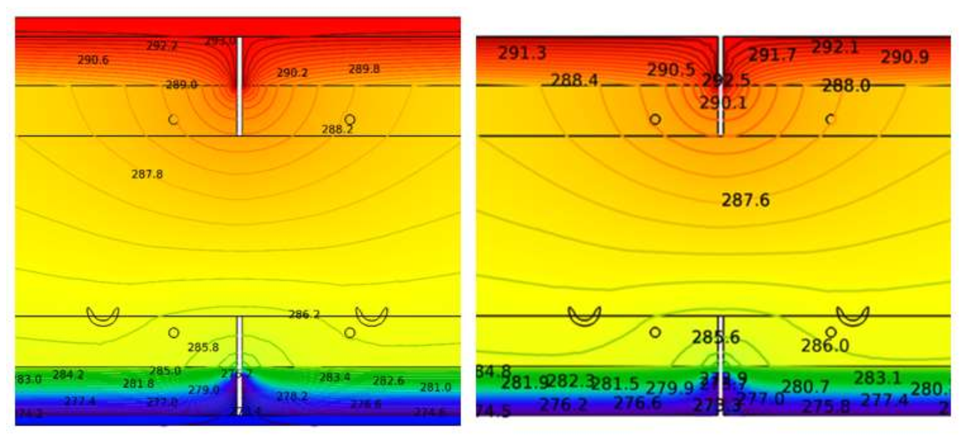
4.2. Design of Construction Joints to Prevent Thermal Bridges
5. Conclusions
Author Contributions
Funding
Institutional Review Board Statement
Informed Consent Statement
Data Availability Statement
Acknowledgments
Conflicts of Interest
References
- Cao, X.; Dai, X.; Liu, J. Building energy-consumption status worldwide and the state-of-the-art technologies for zero-energy buildings during the past decade. Energy Build 2016, 128, 198–213. [Google Scholar] [CrossRef]
- Campagna, L.M.; Fiorito, F. On the Impact of Climate Change on Building Energy Consumptions: A Meta-Analysis. Energies 2022, 15, 354. [Google Scholar] [CrossRef]
- Salvalai, G.; Sesana, M.M.; Iannaccone, G. Deep renovation of multi-storey multi-owner existing residential buildings: A pilot case study in Italy. Energy Build 2017, 148, 23–36. [Google Scholar] [CrossRef]
- Motuzienė, V.; Rogoža, A.; Lapinskienė, V.; Vilutienė, T. Construction solutions for energy efficient single-family house based on its life cycle multi-criteria analysis: A case study. J. Clean. Prod. 2016, 112, 532–541. [Google Scholar] [CrossRef]
- Salvalai, G.; Sesana, M.M.; Brutti, D.; Imperadori, M. Design and Performance Analysis of a Lightweight Flexible nZEB. Sustainability 2020, 12, 5986. [Google Scholar] [CrossRef]
- Ibrahim, M.; Ibrahim, M. Estimating the sustainability returns of recycling construction waste from building projects. Sustain. Cities Soc. 2016, 23, 78–93. [Google Scholar] [CrossRef]
- Kim, S.; Lee, D.-E.; Kim, Y.; Kim, S. Development and Application of Precast Concrete Double Wall System to Improve Productivity of Retaining Wall Construction. Sustainability 2020, 12, 3454. [Google Scholar] [CrossRef] [Green Version]
- Navarro-Rubio, J.; Pineda, P.; García-Martínez, A. Sustainability, prefabrication and building optimization under different durability and re-using scenarios: Potential of dry precast structural connections. Sustain. Cities Soc. 2020, 44, 614–628. [Google Scholar] [CrossRef]
- Zhang, J.; Long, Y.; Lv, S.; Xiang, Y. BIM-enabled Modular and industrialized Construction in China. Procedia Eng. 2016, 145, 1456–1461. [Google Scholar] [CrossRef] [Green Version]
- Zhang, C.; Hu, M.; Laclau, B.; Garnesson, T.; Yang, X.; Li, C.; Tukker, A. Environmental life cycle costing at the early stage for supporting cost optimization of precast concrete panel for energy renovation of existing buildings. J. Build. Eng. 2021, 35, 102002. [Google Scholar] [CrossRef]
- O’Hegarty, R.; Kinnane, O. Review of precast concrete sandwich panels and their innovations. Constr Build Mater. 2020, 233, 117145. [Google Scholar] [CrossRef]
- O’Hegarty, R.; Kinnane, O.; Grimes, M.; Newell, J.; Clifford, M.; West, R. Development of thin precast concrete sandwich panels: Challenges and outcomes. Constr Build Mater 2021, 267, 120981. [Google Scholar] [CrossRef]
- Graziani, L.; Quagliarini, E.; D’Orazio, M.; Lenci, S.; Scalbi, A. A More Sustainable Way for Producing RC Sandwich Panels On-Site and in Developing Countries. Sustainability 2017, 9, 472. [Google Scholar] [CrossRef] [Green Version]
- Mugahed Amran, Y.H.; El-Zeadani, M.; Lee, Y.H.; Lee, Y.Y.; Murali, G.; Feduik, R. Design innovation, efficiency and applications of structural insulated panels: A review. Structures 2020, 27, 1358–1379. [Google Scholar] [CrossRef]
- Expanded Polystyrene-Based Blocks for Formwork and Lightweight Blocks for Simple Formwork. Available online: https://evaluation.cstb.fr/en/certifications-products-services/product/entrevous-en-polystyrene-expanse-et-entrevous-legers-de-coffrage-simple/ (accessed on 21 December 2021).
- KORE Insulating Concrete Formwork System. Available online: https://www.nsai.ie/images/uploads/certification-agrement/IAB080307.pdf (accessed on 21 December 2021).
- Solomon, A.A.; Hemalatha, G. Characteristics of expanded polystyrene (EPS) and its impact on mechanical and thermal performance of insulated concrete form (ICF) system. Structures 2020, 23, 204–213. [Google Scholar] [CrossRef]
- Amer-Yahia, C.; Majidzadeh, T. Inspection of Insulated Concrete Form walls with Ground Penetrating Radar. Constr. Build Mater. 2012, 26, 448–458. [Google Scholar] [CrossRef]
- Sukontasukkul, P.; Sangpet, T.; Newlands, M.; Tangchirapat, W.; Limkatanyu, S.; Chindaprasirt, P. Thermal behaviour of concrete sandwich panels incorporating phase change material. Adv. Build. Energy Res. 2022, 16, 64–88. [Google Scholar] [CrossRef]
- Marani, A.; Madhkhan, M. Thermal performance of concrete sandwich panels incorporating phase change materials: An experimental study. J. Mater. Res. Technol. 2021, 12, 760–775. [Google Scholar] [CrossRef]
- Voellinger, T.; Bassi, A.; Heitel, M. Facilitating the incorporation of VIP into precast concrete sandwich panels. Energy Build. 2014, 85, 666–671. [Google Scholar] [CrossRef]
- Da Gloria, M.Y.R.; Dias Toledo Filho, R. Innovative sandwich panels made of wood bio-concrete and sisal fiber reinforced cement composites. Constr Build Mater. 2021, 272, 121636. [Google Scholar] [CrossRef]
- Šahmenko, G.; Šinka, M.; Namsone, E.; Korjakins, A.; Bajāre, D. Sustainable Wall Solutions Using Foam Concrete and Hemp Composites. Environ. Clim. Technol. 2021, 25, 917–930. [Google Scholar] [CrossRef]
- Chippagiri, R.; Gavali, H.R.; Ralegaonkar, R.V.; Riley, M.; Shaw, A.; Bras, A. Application of Sustainable Prefabricated Wall Technology for Energy Efficient Social Housing. Sustainability 2021, 13, 1195. [Google Scholar] [CrossRef]
- Šantek Bajto, J.; Štirmer, N.; Cerković, S.; Carević, I.; Kostanić Jurić, K. Pilot Scale Production of Precast Concrete Elements with Wood Biomass Ash. Materials 2021, 14, 6578. [Google Scholar] [CrossRef]
- Rodriguez, C.; Miñano, I.; Parra, C.; Pujante, P.; Benito, F. Properties of Precast Concrete Using Food Industry-Filtered Recycled Diatoms. Sustainability 2021, 13, 3137. [Google Scholar] [CrossRef]
- Dissanayake, D.M.K.W.; Jayasinghe, C.; Jayasinghe, M.T.R. A comparative embodied energy analysis of a house with recycled expanded polystyrene (EPS) based foam concrete wall panels. Energy Build. 2017, 135, 85–94. [Google Scholar] [CrossRef]
- Fernando, P.L.N.; Jayasinghe, M.T.R.; Jayasinghe, C. Structural feasibility of Expanded Polystyrene (EPS) based lightweight concrete sandwich wall panels. Constr Build Mater. 2017, 139, 45–51. [Google Scholar] [CrossRef]
- Awan, A.B.; Shaikh, F.U.A. Compressive behavior of precast concrete sandwich panels containing recycled tyre crumb rubber core. Struct. Concr. 2021, 22, 3602–3619. [Google Scholar] [CrossRef]
- Lee, B.-J.; Pessiki, S. Thermal performance evaluation of precast concrete three-wythe sandwich wall panels. Energy Build. 2006, 38, 1006–1014. [Google Scholar] [CrossRef]
- Zhai, X.; Wang, Y.; Wang, X. Thermal performance of precast concrete sandwich walls with a novel hybrid connector. Energy Build. 2018, 166, 109–121. [Google Scholar] [CrossRef]
- Kim, Y.J.; Allard, A. Thermal response of precast concrete sandwich walls with various steel connectors for architectural buildings in cold regions. Energy Build. 2014, 80, 137–148. [Google Scholar] [CrossRef]
- Scioti, A.; Pierucci, A.; De Fino, M.; Fatiguso, F. Pre-casting, recycle and performance efficiency for sustainable construction components. In Proceedings of the CIB World Building Congress 2019 “Constructing Smart Cities”, Hong Kong, China, 17–21 June 2019. [Google Scholar]
- Scioti, A. Pre-cast concrete walls: Techniques and technologies for performance optimization. TEMA 2015, 1, 83–88. [Google Scholar]
- Wu, S.; Li, H.; Wang, X.; Li, R.; Tian, C.; Hou, Q. Seismic performance of a novel partial precast RC shear wall with reserved cast-in-place base and wall edges. Soil Dyn. 2022, 152, 107038. [Google Scholar] [CrossRef]
- Jiang, J.; Luo, J.; Xue, W.; Hu, X.; Qin, D. Seismic performance of precast concrete double skin shear walls with different vertical connection types. Eng. Struct. 2021, 245, 112911. [Google Scholar] [CrossRef]
- Lu, X.; Memari, A. Comparative Energy Analysis and Life-Cycle Assessment of Innovative Residential Wall Systems in Cold Regions. Pract. Period. Struct. 2019, 24, 04019015. [Google Scholar] [CrossRef]
- Hachem-Vermette, C. Selected High-Performance Building Envelopes. In Solar Buildings and Neighborhoods; Green Energy and Technology; Springer: Berlin/Heidelberg, Germany, 2020; pp. 67–100. [Google Scholar]
- Cruz, A.S.; Cunha, E.G. The impact of climate change on the thermal-energy performance of the SCIP and ICF wall systems for social housing in Brazil. Indoor Built Environ. 2021. Available online: https://journals.sagepub.com/doi/abs/10.1177/1420326X211038047 (accessed on 1 January 2022). [CrossRef]
- Nibhanupudi, P.; Rahul, G.B. Comparative study on use of precast framed structure and precast load bearing wall structure. Mater. Today Proc. 2020, 33, 537–542. [Google Scholar] [CrossRef]
- Hilal, N.; Hamah Sor, N.; Faraj, R.H. Development of eco-efficient lightweight self-compacting concrete with high volume of recycled EPS waste materials. Environ. Sci. Pollut. Res. 2021, 28, 50028–50051. [Google Scholar] [CrossRef]
- Mohammed, H.J.; Hussein, Y.G. Concrete Properties using Treated Recycled EPS. IOP Conf. Ser. Earth Environ. Sci. 2021, 877, 012028. [Google Scholar] [CrossRef]
- Gopinathan, M.J.; Subramanian, K. High Performance and Efficiency of Joints in Precast Members. Int. J. Eng. Sci. Technol. 2013, 5, 4002–4009. [Google Scholar]
- Lu, Z.; Wu, B.; Yang, S.; Hou, J.; Ji, Z.; Li, Y.; Huang, J.; Zhang, M. Experimental study on flexural behaviour of prefabricated concrete beams with double-grouted sleeves. Eng. Struct. 2021, 248, 113237. [Google Scholar] [CrossRef]
- Gonçalves, M.; Simões, N.; Serra, C.; Flores-Colen, I.; Rottenbacher, K.; Flávia, A. Almeida, Study of the edge thermal bridging effect in vacuum insulation panels: Steady and unsteady-state approaches using numerical and experimental methods. Energy Build. 2022, 258, 111821. [Google Scholar] [CrossRef]
- Gonçalves, M.; Simões, N.; Serra, C.; Flores-Colen, I. A review of the challenges posed by the use of vacuum panels in external insulation finishing systems. Appl. Energy 2020, 257, 2020. [Google Scholar] [CrossRef]
- Song, J.H.; Lim, J.H.; Song, S.Y. Evaluation of alternatives for reducing thermal bridges in metal panel curtain wall systems. Energy Build. 2016, 127, 138–158. [Google Scholar] [CrossRef]
- Sorensen, T.; Thomas, R.; Dorafshan, S.; Maguire, M. Thermal Bridging in Concrete Sandwich Walls. Concr. Int. 2018, 40, 45–49. [Google Scholar]
- Martiradonna, S.; Fatiguso, F.; Lombillo, I. Thermal improvements of the existing reinforced concrete buildings by the precast concrete panel system. In Proceedings of the Colloqui.AT.e 2020—New Horizons for Sustainable Architecture, Catania, Italy, 10 January 2022. [Google Scholar]
- Gencel, O.; del Coz Díaz, J.J.; Sutcu, M.; Kocyigit, F.; Rabanal, F.P.Á.; Alonso-Martínez, M.; Barrera, G.M. Thermal Performance Optimization of Lightweight Concrete/EPS Layered Composite Building Blocks. Int. J. Thermophys. 2021, 42, 52. [Google Scholar] [CrossRef]
- UNI EN ISO 10456:2008. Building Materials and Products—Hygrothermal Properties—Tabulated Design Values and Procedures for Determining Declared and Design Thermal Values. Available online: http://store.uni.com/catalogo/uni-en-iso-10456-2008 (accessed on 12 November 2021).
- UNI EN ISO 13788:2013. Hygrothermal Performance of Building Components and Building Elements—Internal Surface Temperature to Avoid Critical Surface Humidity and Interstitial Condensation—Calculation Methods. Available online: http://store.uni.com/catalogo/uni-en-iso-13788-2013 (accessed on 12 November 2021).
- UNI EN 12667:2002. Thermal Performance of Building Materials and Products—Determination of Thermal Resistance by Means of Guarded Hot Plate and Heat Flow Meter Methods—Products of High and Medium Thermal Resistance. Available online: http://store.uni.com/catalogo/uni-en-12667-2002 (accessed on 12 November 2021).
- ISO 12572:2016. Hygrothermal Performance of Building Materials and Products—Determination of Water Vapour Transmission Properties—Cup Method. Available online: http://store.uni.com/catalogo/iso-12572-2016 (accessed on 12 November 2021).
- UNI EN 12390-2:2019. Testing Hardened Concrete—Part 2: Making and Curing Specimens for Strength Tests. Available online: http://store.uni.com/catalogo/uni-en-12390-2-2019 (accessed on 17 December 2021).
- UNI EN 12390-3:2019. Testing Hardened Concrete—Part 3: Compressive Strength of Test Specimens. Available online: http://store.uni.com/catalogo/uni-en-12390-3-2019 (accessed on 17 December 2021).
- UNI EN 12390-4:2019. Testing Hardened Concrete—Part 4: Compressive Strength—Specification for Testing Machines. Available online: http://store.uni.com/catalogo/uni-en-12390-4-2019 (accessed on 17 December 2021).
- UNI EN 206:2021. Concrete—Specification, Performance, Production and Conformity. Available online: http://store.uni.com/catalogo/uni-en-206-2021 (accessed on 17 December 2021).
- NTC2018. Italian Technical Normative for Construction. Available online: http://www.ingegneriasoft.com/pdf/Norme_Tecniche_Costruzioni_2018_NTC2018_NTC.pdf (accessed on 22 January 2022).
- DPR n. 412, 26 August 1993. Regulation Laying Down Rules for the Design, Install Ation, Operation and Maintenance of the Thermal Systems of the Buildings for the Purpose of Containment of Energy Consumption. Available online: https://www.gazzettaufficiale.it/eli/id/1993/10/14/093G0451/sg (accessed on 22 January 2022). (In Italian).


| Material | Density (kg/m3) | TC 1 (W/mK) | TD 1 (10−6 m2/s) | VHC 1 (106 J/m3K) | WVP 1 (10−12 kg/(m s Pa)) | WVRF 1 (-) |
|---|---|---|---|---|---|---|
| EPS0 | 10 | 0.0391 | 1.180 | 0.033 | 7.03 | 27.5 |
| C0 | 2189.0 | 1.77 | 1.01 | 1.77 | 3.61 | 53.76 |
| Layer | Thickness (m) | TC 1 (W/mK) | TR 1 (m2K/W) |
|---|---|---|---|
| RSI 2 | 0.13 | ||
| EPS0 | 0.05 | 0.039 | 1.282 |
| C0 | 0.25 | 2.5 | 0.10 |
| EPS0 | 0.05 | 0.039 | 1.282 |
| RSE 2 | 0.04 | ||
| WR 3 (m2K/W) | 2.83 | ||
| WT 3 (W/m2K) | 0.35 | ||
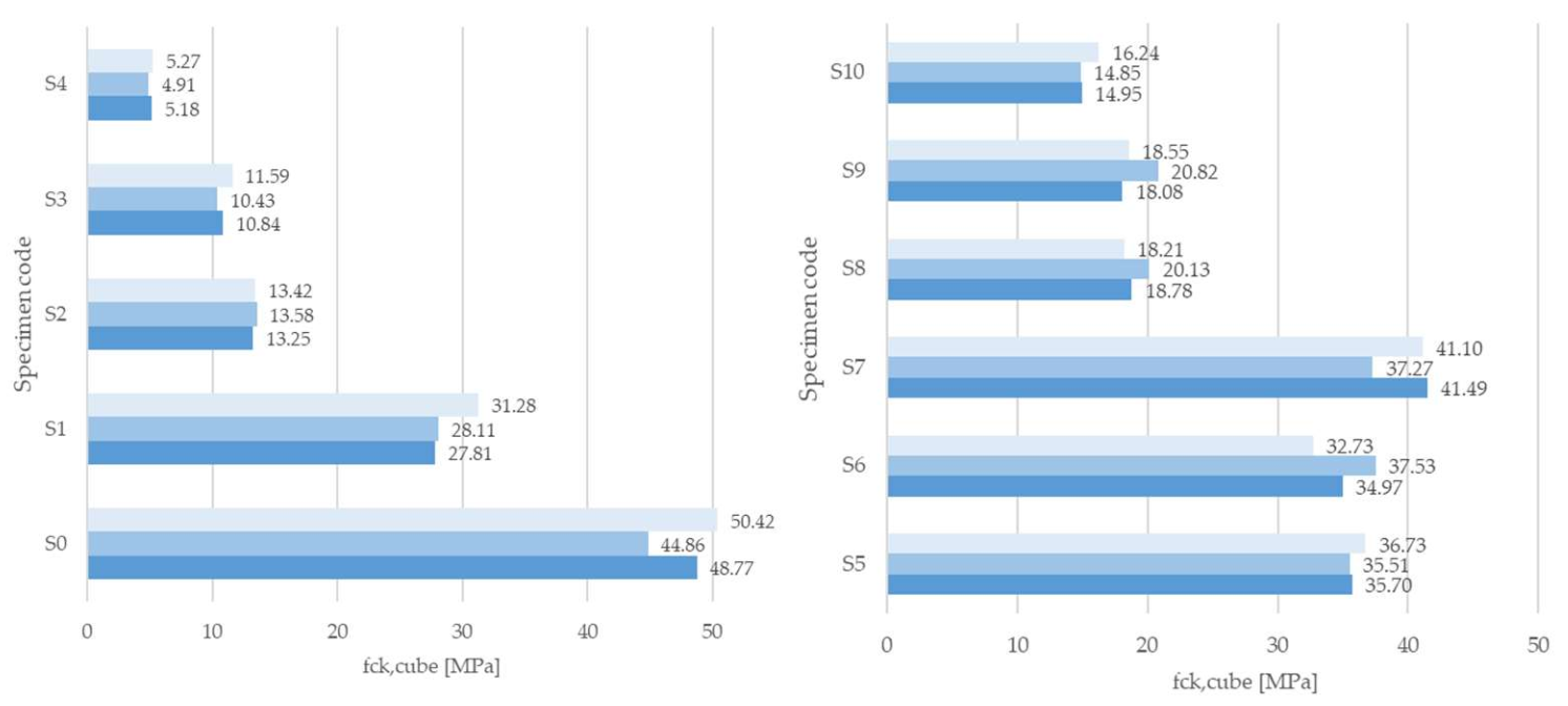
| Code | EPS | SAND | ||||||||||
|---|---|---|---|---|---|---|---|---|---|---|---|---|
| Grain Size (mm) | Grain Size (mm) | |||||||||||
| 0–0.5 | 0.5–1 | 1–2 | 2–4 | 4–6 | 6–8 | 0–0.5 | 0.5–1 | 1–2 | 2–4 | 4–6 | 6–8 | |
| S0 | 100%V | |||||||||||
| S1 | 25% | 75%V | ||||||||||
| S2 | 50% | 50%V | ||||||||||
| S3 | 75% | 25%V | ||||||||||
| S4 | 100% | |||||||||||
| S5 | V(1–2) | V(0–1) | V(2–4) | |||||||||
| S6 | V(2–4) | V(0–2) | V(4–8) | |||||||||
| S7 | V(4–8) | V(0–4) | ||||||||||
| S8 | V(1–4) | V(0–1) | V(4–8) | |||||||||
| S9 | V(2–8) | V(0–2) | ||||||||||
| S10 | V(1–8) | V(0–1) | ||||||||||
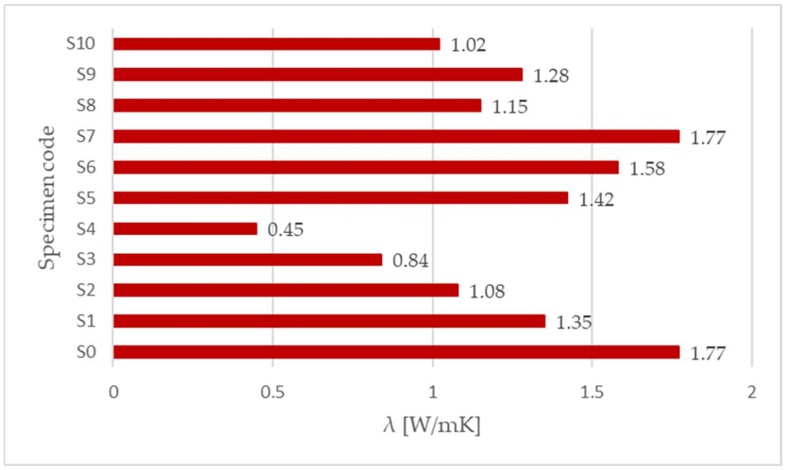
| Specimen Code | Density (kg/m3) | TC 1 (W/mK) | TD 1 (10−6 m2/s) | VHC 1 (106 J/m3K) |
|---|---|---|---|---|
| S0 | 2189.0 | 1.77 | 1.01 | 1.77 |
| S1 | 1974.9 | 1.35 | 0.83 | 1.63 |
| S2 | 1667.1 | 1.08 | 0.64 | 1.68 |
| S3 | 1377.3 | 0.84 | 0.56 | 1.52 |
| S4 | 1397.5 | 0.45 | 0.33 | 1.38 |
| S5 | 1973.31 | 1.42 | 0.87 | 1.64 |
| S6 | 2071.57 | 1.58 | 0.95 | 1.67 |
| S7 | 2147.27 | 1.77 | 1.02 | 1.73 |
| S8 | 1798.78 | 1.15 | 0.71 | 1.62 |
| S9 | 1892.38 | 1.28 | 0.80 | 1.60 |
| S10 | 1603.74 | 1.02 | 0.63 | 1.61 |
| Specimen Code | WVP 1 (10−12 kg/(m s Pa)) | WVRF 1 (-) |
|---|---|---|
| S0 | 3.61 | 53.76 |
| S1 | 4.65 | 41.59 |
| S2 | 4.57 | 42.46 |
| S3 | 7.58 | 26.45 |
| S4 | 6.60 | 29.29 |
| S5 | 7.34 | 26.29 |
| Specimen Code | Structural | Non-Structural | Lightweight | Normal |
|---|---|---|---|---|
| S1 | x | x | ||
| S2 | x | x | ||
| S3 | x | x | ||
| S4 | x | x | ||
| S5 | x | x | ||
| S6 | x | x | ||
| S7 | x | x | ||
| S8 | x | x | ||
| S9 | x | x | ||
| S10 | x | x |
| Wall Layer | Thickness (m) | Density (Kg/m3) | TC 1 (W/mK) | WVRF 1 (-) |
|---|---|---|---|---|
| Indoor heat transfer coefficient | 7.70 | |||
| EPS | 50 | 10 | 0.04 | 27.5 |
| S0 | 50 | 2189 | 1.77 | 53.7 |
| S1 | 150 | 1975 | 1.35 | 41.6 |
| S0 | 50 | 2189 | 1.77 | 53.7 |
| EPS | 50 | 10 | 0.04 | 27.5 |
| Outdoor heat transfer coefficient | 25 |
Publisher’s Note: MDPI stays neutral with regard to jurisdictional claims in published maps and institutional affiliations. |
© 2022 by the authors. Licensee MDPI, Basel, Switzerland. This article is an open access article distributed under the terms and conditions of the Creative Commons Attribution (CC BY) license (https://creativecommons.org/licenses/by/4.0/).
Share and Cite
Scioti, A.; De Fino, M.; Martiradonna, S.; Fatiguso, F. Construction Solutions and Materials to Optimize the Energy Performances of EPS-RC Precast Bearing Walls. Sustainability 2022, 14, 3558. https://doi.org/10.3390/su14063558
Scioti A, De Fino M, Martiradonna S, Fatiguso F. Construction Solutions and Materials to Optimize the Energy Performances of EPS-RC Precast Bearing Walls. Sustainability. 2022; 14(6):3558. https://doi.org/10.3390/su14063558
Chicago/Turabian StyleScioti, Albina, Mariella De Fino, Silvia Martiradonna, and Fabio Fatiguso. 2022. "Construction Solutions and Materials to Optimize the Energy Performances of EPS-RC Precast Bearing Walls" Sustainability 14, no. 6: 3558. https://doi.org/10.3390/su14063558
APA StyleScioti, A., De Fino, M., Martiradonna, S., & Fatiguso, F. (2022). Construction Solutions and Materials to Optimize the Energy Performances of EPS-RC Precast Bearing Walls. Sustainability, 14(6), 3558. https://doi.org/10.3390/su14063558