Article

SEBS-Polymer-Modified Slag–Cement–Bentonite for Resilient Slurry Walls

1
Department of Engineering, University of Cambridge, Cambridge CB2 1PZ, UK
2
State Environmental Protection Key Laboratory of Soil Environmental Management and Pollution Control, Nanjing Institute of Environmental Sciences, Ministry of Ecology and Environment of China, Nanjing 210042, China
3
College of Environmental Science and Engineering, Tongji University, Shanghai 200092, China
*
Author to whom correspondence should be addressed.
Sustainability 2022, 14(4), 2093; https://doi.org/10.3390/su14042093
Submission received: 11 January 2022 / Revised: 29 January 2022 / Accepted: 7 February 2022 / Published: 12 February 2022
(This article belongs to the Special Issue Biomimetic Infrastructure Materials: Towards a Greener Future)

Abstract

:
In spite of the well-established design and construction approaches of slag–cement–bentonite slurry walls, the materials deteriorate inevitably in contaminated land. The development of effective materials which are sustainable, resilient and self-healing over the lifetime of slurry walls becomes essential. This study, for the first time, adopts a styrene–ethylene/butylene–styrene (SEBS) polymer to modify slag–cement–bentonite materials to enhance mechanical and self-healing performance. The results show that the increase in SEBS dosage results in significantly increased strain at failure, indicating the enhanced ductility thanks to the modification by the deformable polymer. The increased ductility is beneficial as the slurry wall could deform to a greater extent without cracks. After the permeation of liquid paraffin, the SEBS exposed on the crack surface swells and seals the crack, with the post-healing permeability only slightly higher than the undamaged values, which exhibits good self-healing performance. Scanning electron microscopy and micro-computed tomography analyses innovatively reveal the good bonding and homogeneous distribution of SEBS in slag–cement–bentonite. SEBS acts as a binder to protect the slag–cement–bentonite sample from disintegration, and the swollen SEBS particles effectively seal and heal the cracks. These results demonstrate that the SEBS-modified slag–cement–bentonite could provide slurry walls with resilient mechanical properties and enhanced self-healing performance.

1. Introduction

The in situ treatment of contaminated land has usually involved either source removal or pathway management, and the installation of physical barriers to contain the contaminants is becoming more widespread. The cement–bentonite slurry trench wall is one of the most common ground barrier systems for underground water and contaminant containment [1]. The technology has developed from cut-off walls for dams and hence is particularly resistant to high hydraulic gradients [2]. The cement–bentonite slurry is produced by hydrating bentonite slurry and mixing it with cement before discharging it into a 0.5–1 m wide trench. The water-to-cement ratios are typically in the range of 10:1 to 3:1. Without bentonite such high water-to-cement ratios would lead to rapid settlement of cement particles to produce free water and a sediment. In cement–bentonite slurry it is the structure of hydrated bentonite gel that limits bleeding. The traditional composition of the slurry consists of Portland ordinary cement (OPC) and sodium bentonite [3,4]. Recently, supplementary cementitious materials, including fly ash and ground granulated blast-furnace slag (GGBS), manufactured from a by-product of the iron-making industry, have become a more sustainable cement substitute [5,6,7]. Improved workability, increased strength, reduced permeability, alkali silica reaction mitigation and improved resistance to chemical attack can all be reasonably expected when fly ash and slag are used as supplementary cementitious materials. Opdyke and Evans [8] investigated the effects of GGBS addition on the mechanical and transport properties of slag–cement–bentonite mixes. They found that when GGBS was added to replace 60% to 80% of cement, the unconfined compressive strength (UCS) and permeability were enhanced significantly.
In spite of the well-established design and construction approaches of slag–cement–bentonite slurry walls, the materials deteriorate inevitably in contaminated land [3,9,10,11]. The damage of slurry walls can result in undermined strength and durability, affecting their sustainability and even leading to undetected physical damage of the wall. For example, the variation in hydraulic conductivity with increasing deformation of slag–cement–bentonite was investigated by Alzayani [12]. The hydraulic conductivity drastically rose after the peak load was reached to be 1.3 × 10⁻⁸ m/s in comparison with the initial permeability of 4.6 × 10⁻⁹ m/s. It continued to increase significantly at the post-peak state, ranging between 10−6 and 10−7 m/s, much higher than the recommended hydraulic conductivity of 1.0 × 10⁻⁸ m/s.
Therefore, the development of effective materials which are sustainable, resilient and self-healing over the lifetime of slurry walls becomes essential. To a certain degree compositional modification can alleviate these concerns by postponing the effects of damage [13]. Polymer-based self-healing approaches have been investigated for the development of resilient oil well cement materials [14]. Lu et al. [15] synthesized an oil swellable polymer with a size of ~180 nm by copolymerizing styrene, butyl acrylate and octadecyl acrylate as functional monomers via radical polymerization. The inclusion of the long alkyl side chains from the functional monomers made the synthesized polymer oleophilic and swellable, with a sorption capacity of 7 g/g in diesel. Pore structure measurement showed that the addition of the oil-swellable polymer decreased the porosity of the cement, indicating the precipitation of the polymer film on the surface of the cement particles. The addition of the polymer increased the oil sorption ability of cement and more significantly increased the swelling capacity upon oil sorption. The self-healing performance in terms of crack closure in the polymer-containing cement samples was examined by an oil permeation test under different pressures. After the polymer-containing cement sample was immersed in an oil bath for a certain period of time, the oil permeation through a crack was clearly inhibited. However, previous studies failed to reveal the mechanical effects and 3D microstructure of the polymer embedded in the cementitious matrix.
In this study, the styrene–ethylene/butylene–styrene (SEBS) polymer was innovatively adopted to modify the slag–cement–bentonite material to enhance mechanical and self-healing performance. The absorption and swelling behavior of the SEBS polymer used in this study were first tested and characterized using thermogravimetric analysis (TGA) and Fourier-transform infrared spectroscopy (FTIR) techniques. After understanding its characteristics, SEBS was added in slag–cement–bentonite slurry. The effects of SEBS on the properties of slag–cement–bentonite were, for the first time, studied. In addition, the modified mechanical and self-healing performance was evaluated by examining the stress–strain response and recovery of permeability. The microstructure and morphology of SEBS in the cementitious matrix were revealed using scanning electron microscopy energy-dispersive X-Ray (SEM-EDX) and micro-computed tomography (micro-CT) techniques. These results demonstrate that the SEBS-modified slag–cement–bentonite could provide slurry walls with resilient mechanical properties and enhanced self-healing performance. The successful development of such a resilient and self-healing slurry wall barrier has the potential to yield substantial repair and maintenance savings and to enhance the durability and serviceability of contaminated land containment applications.

2. Materials and Methods
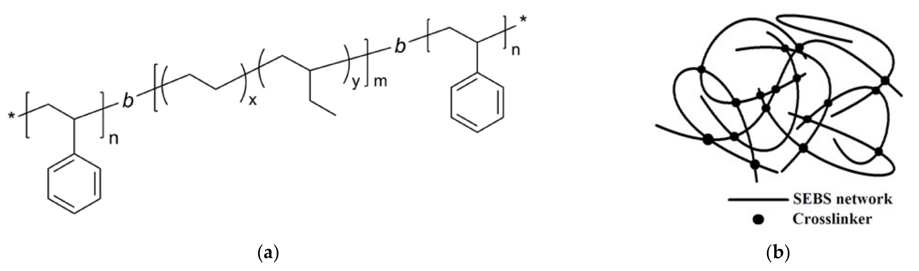
2.1. SEBS Polymer

The SEBS polymer used in this study is a form of thermoplastics elastomer. The chemical structure and polymer network model are shown in Figure 1. SEBS was produced by partial and selective hydrogenating of styrene–butadiene–styrene copolymer which improves the thermal stability and weathering resistance. After hydrogenation, electron irradiation was applied to induce the formation of a cross-linked network structure through the free-radical mechanism. During exposure to irradiation, the generation of free radicals on the vinyl group of the butene and styrene segments and simultaneous formation of a C–C bond through inter/intra-molecular crosslinking produced the three-dimensional network structure of cross-linked SEBS [16]. Polymer chains are interlaced on a molecular scale, and this polymer network cannot be separated unless chemical bonds are broken.
The SEBS polymer is commercially available and delivered in the form of rubbery particles with a bulk density of around 350 kg/m3 and a specific gravity of 0.91 g/cm3. The SEBS were crushed into single particles after the polymerization process; these particles therefore had irregular shapes. It can be noted in the SEM image that the SEBS particle had a very porous structure, which increases the specific area and facilitates the migration of organic liquid into the SEBS particle (Figure 2). These interstices on the surface also contribute to rapid organic sorption by capillary action. EDX analysis shows that carbon was the only element detected, which suggests that the SEBS were pure hydrocarbon.

2.2. Slag–Cement–Bentonite

A CEM-I 52.5N cement with a particle density of 2.7–3.2 g/cm3, supplied by Hanson Limited, UK, was used. The ground granulated blast-furnace slag (GGBS), which is a by-product cement substitute, used in this study was Regen GGBS supplied by Hanson Limited, UK, with a particle density of around 2.9 g/cm3. A sodium-activated bentonite produced to OCMA standard with a particle density of 2.4–2.6 g/cm3 obtained from Macromin Kentish Minerals, UK, was used. The bentonite was a pale-colored fine-grained powder, and more than 75% of the bentonite passed through a 75 µm (No. 200) sieve. The chemical compositions of the cement, GGBS and bentonite are detailed in Table 1.
All slag–cement–bentonite mixes were prepared in a lab mixer with a rotational speed of 190 rpm. The bentonite was first mixed with water for ten minutes to ensure the formation of a uniform bentonite slurry. The bentonite slurry was then left to hydrate for 24 h, after which the dry cement, GGBS and SEBS were added. Cylinder specimens with a height of 100 mm and diameter of 50 mm were prepared. These specimens were left to cure in an incubator at a temperature of 21 °C and 100% RH. Table 2 shows the mix constituents and nomenclatures.

2.3. Experimental Methods

The absorption capacity of the SEBS polymer was determined using a filtration test. Different organic liquids were dropped to 1.0 g dry SEBS polymer and the mix was vacuum filtered after 24 h. The weight difference between the dry and saturated state is calculated as the absorption capacity.
Fourier-transform infrared spectroscopy (FTIR) analysis was carried out to investigate the fundamental vibrations and associated rotational–vibrational structure. The infrared spectrum of the SEBS samples before and after sorption was obtained using a Perkin Elmer FTIR spectrometer to examine the change in microstructure. Scans were taken from 4000 to 400 cm−1 with a resolution of 4 cm−1.
Thermogravimetric analyses (TGA) of SEBS were conducted using a Perkin Elmer STA 6000. Approximately 10 mg SEBS was used in the tests. During the tests the sample weight and temperature were measured with high precision while the samples were heated up from 30 to 600 °C at an increase rate of 10 °C/min. Thermogravimetric result curves and the first derivative of the thermogravimetric (DTG) result curves were obtained by plotting normalized sample weight with temperature.
The unconfined compressive strength (UCS) was obtained in triplicate cylinder specimens according to ASTM: D4219-08 [17] using a Controls Testing Uniframe 70-T0108/E loading frame. The UCS test was started by applying a constant axial displacement rate of 1.0 mm per minute until the peak force was reached. A linear variable differential transformer was utilized to measure the axial deformation to calculate the axial strain.
The hydraulic conductivity of the specimens was measured using the flexible-wall permeability method in triaxial cells according to ASTM: D5084-16 [18]. The cell pressure of 100 kPa was applied and maintained during the test. A peristaltic pump was connected to the base of the cell and a flow of water was permeated into the cylinder specimen from the bottom to the top. The pore water pressure generated by the water flow was measured with a pressure transducer connected to the inflow pipe. The first permeability tests were conducted on the undamaged specimens after 28-day curing, after which the specimens were cracked using the UCS testing frame until the force reached its peak value. The second permeability tests were carried out on the day of cracking, and then the cracked specimens were permeated with liquid paraffin for six hours before the third permeability tests on the post-healing specimens.
Phenom Pro X SEM was used to characterize the microstructural surface morphology of the sample with SEBS, and EDX was used to analyze the elemental composition. Small chips extracted from the cracked slag–cement–bentonite specimens were vacuum dried at 20 °C for 24 h before being scanned. Samples were scanned under the secondary electron mode and images were captured at different magnifications at a 10 kV accelerating voltage. EDX was carried out to determine the chemical composition of the material interested at a 15 kV accelerating voltage.
The micro-CT scan produces a 3D distribution of the local linear attenuation coefficient of the sample in the form of grey values, and specialized rendering software (VGStudio MAX) allows for visual inspection of this 3D volume. Cubic slag–cement–bentonite samples, around 10 × 10 × 10 mm3, were cut from the cylinder specimens and scanned innovatively using the Nikon XT H 225 ST scanner.

3. Results and Discussion

3.1. Sorption Capacities and Microstructure of SEBS

The SEBS polymer used in this study primarily takes up organic liquids through absorption, and the absorption process depends mostly on polymer–liquid interaction and diffusion [19]. The amounts of absorbed organic liquids by the SEBS are quantified in Figure 3. The SEBS readily absorbs pure straight-chain hydrocarbons with the number of carbon atoms less than 10, such as hexane (C6H14), a significant constituent of gasoline, up to an absorption capacity of 22.6 g/g. This is due to the strong oil–substrate interaction. The absorption capacities for liquid paraffin and mineral oil were also high at 12.4 and 9.9 g/g. This study used liquid paraffin as the permeation liquid in the permeability tests because it is highly stable and less toxic compared to other organic liquids.
FTIR tests were carried out to investigate the chemical structure of the neat SEBS polymer after the absorption of liquid paraffin. The FTIR spectra with frequency peaks corresponding to different chemical functional groups of the two samples are shown in Figure 4. SEBS contains aliphatic and aromatic hydrocarbon groups, and the assignments of the most typical bands of neat SEBS were extensively reported in the literature [16,20,21]. In the SEBS polymer, the characteristic bands at 697 and 750 cm−1 were attributed to the out-of-plane C-H deformation in the aromatic ring due to the styrene moiety present in the SEBS elastomer, while the smaller peak at 720 cm−1 was characteristic for the aliphatic C-H bending vibrations. The bands at 1453 and 1378 cm−1 were attributed to asymmetric methyl bending vibration (-CH3) and methylene wagging deformation (-CH2). Moreover, the stretching vibration absorption peaks of -CH2 appeared at around 2918 and 2844 cm−1. The SEBS after absorbing liquid paraffin had a similar FTIR spectrum to the neat polymer, especially for the absorbance bands corresponding to aliphatic functional groups. The major difference between the neat and swollen SEBS lay in the absorbance bands in the range of 750 to 690 cm−1, which were primarily attributed to the aromatic ring in the styrene moiety. The decrease in the peak intensity over this range indicated that the content of aromatic ring was reduced in the saturated polymer. This is because liquid paraffin has simple straight chains of alkanes with a chemical composition of CnH2n+2, and therefore the content of the aromatic ring in the saturated polymer was relatively reduced by the absorbed saturated hydrocarbon. The absence of new peaks or frequency shifts in the FTIR spectrum of the swollen SEBS indicated that the sorption process of liquid paraffin exhibited absorption (not adsorption).
The effect of oil absorption on the thermal stability of the SEBS was investigated using TGA tests. The TGA tests were conducted on the neat SEBS after the absorption of liquid paraffin, and the variations of the mass loss and differential thermogravimetry (DTG) with the temperature are presented in Figure 5. The neat SEBS remained thermally constant up to 250 °C, whereas the SEBS saturated with liquid paraffin started losing weight gradually at 150 °C. There was degradation between 250 and 450 °C for the neat SEBS, and the DTG peaks appeared at 380 °C and 530 °C. The SEBS polymer backbone began to degrade at 250 °C and was completely oxidized after 550 °C [22]. During the heating process of SEBS, the decomposition, scission, and oxidation of the polymer chain occurs mainly at the boundary of styrene–olefin phase. These structural changes result in acetone end groups on the styrene units and carboxylic acids on the olefin chain ends [16]. The absorption of liquid paraffin decreased the thermal stability of the swollen SEBS, with the first DTG peak shifting to 290 °C compared to the 380 °C for the neat SEBS. The early onset of mass loss after the absorption was caused by the thermal degradation of liquid paraffin, which started to decompose into smaller hydrocarbons at ~150 °C [23]. It should be noted that the chemical structure of the SEBS polymer was not affected by the absorption of liquid paraffin as discussed earlier in the FTIR analysis, despite a lower onset temperature of mass loss due to the degradation of the absorbed oil. The temperature of geotechnical and geoenvironmental slurry wall applications is usually at ~30 °C and not higher than 50 °C [24], so that both of the neat and swollen SEBS can remain good thermal stability during the construction of slurry walls.

3.2. Rheological Properties of SEBS-Modified Slurry

The proper rheological behavior of fresh slag–cement–bentonite slurry plays an important role in the successful construction of slurry walls, as the pumpability is primarily governed by the viscosity. The effects of SEBS addition were studied, and the values of plastic viscosity and yield stress are shown in Figure 6. These values appear to increase linearly with increased SEBS content. The plastic viscosities for samples containing 0, 2% and 4% SEBS were 13.5, 26.7 and 53.2 mPa·s, respectively. When the flowability drops, the initiation of slurry flow requires higher energy, leading to increased yield stress. The yield stress of the SEBS-2% and SEBS-4% increased to 22.9 and 31.5 Pa from the control value of 14 Pa. It is recommended that the plastic viscosity of the fresh slag–cement–bentonite slurry range from 12 to 78 mPa·s to achieve good pumpability [25]. It should be noted that all the SEBS-modified mixes meet the workability requirement, with plastic viscosity values below 78 mPa·s. This indicates that SEBS incorporation at a dosage of up to 4% is reasonable, in terms of rheological properties, for the slurry trench wall applications.

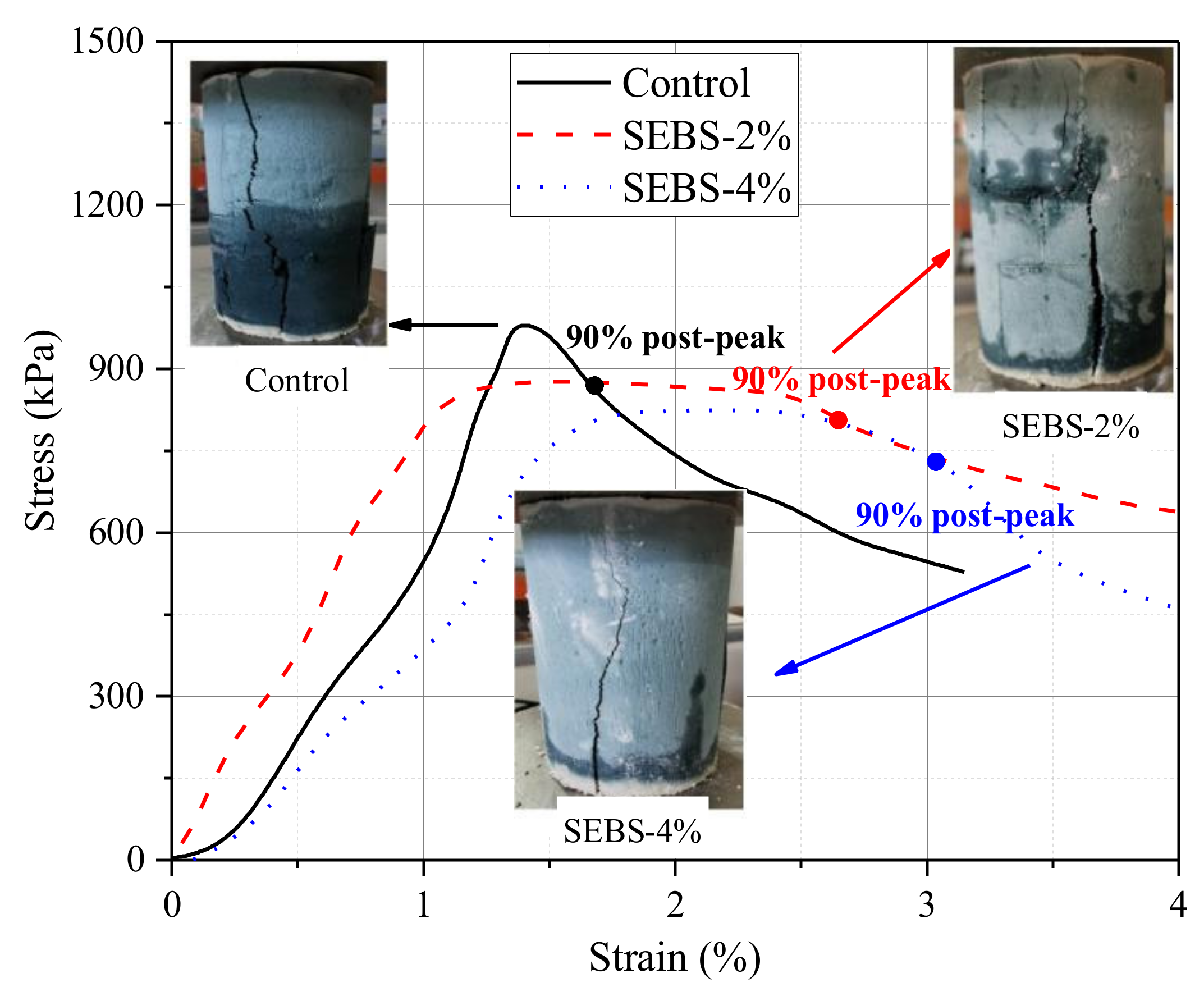
3.3. Mechanical Properties of SEBS-Modified Slag–Cement–Bentonite

The values of UCS and strain at failure of slag–cement–bentonite specimens with and without SEBS are shown in Figure 7. After 28 days of curing, SEBS had a negligible effect on the UCS and strain at failure regardless of the dosage. However, the effects of SEBS addition on the mechanical properties became visible after 90 days of curing. In general, the increase in SEBS dosage resulted in reduced UCS and increased strain at failure. The 90-day UCS decreased by 7.6% and 8.7% for SEBS-2% and SEBS-4%, compared with the control value of 1049 kPa. The SEBS polymer is an elastomer with a low Young’s modulus and high failure strain (600%) compared with cementitious materials [26]. Therefore, the SEBS particles are unable to bear or transmit load in the cementitious matrix due to their low stiffness, acting as defects, which was considered harmful to the strength. The values of strain at failure of SEBS-2% and SEBS-4% increased by 15% and 38% compared to the control at 90 days.
The representative stress–strain curves and crack patterns of the control and SEBS-modified slag–cement–bentonite specimens were investigated after 90 days of curing, as shown in Figure 8. All the specimens showed a tensile failure mode with a major vertical crack along the generatrix of the cylinder samples. The SEBS-2% and SEBS-4% specimens exhibited a much longer strain-softening section than the control after the peak force was reached. The strains at 90% post-peak strength were 2.7% and 3.0% for SEBS-2% and SEBS-4% samples, compared with the control value of 1.7%. The stress–strain behavior of SEBS-modified slag–cement–bentonite became more ductile as the SEBS content increased, suggesting that the decreased stiffness is due to the incorporation of the deformable polymer. This is comparable to the enhanced post-peak tension-softening behavior observed in fiber-modified cementitious composites. Fiber-modified cementitious composites that were reinforced with a low volume of fibers, typically 0.5–2%, have a strain-softening response and demonstrate an increase in post-peak ductility [27].

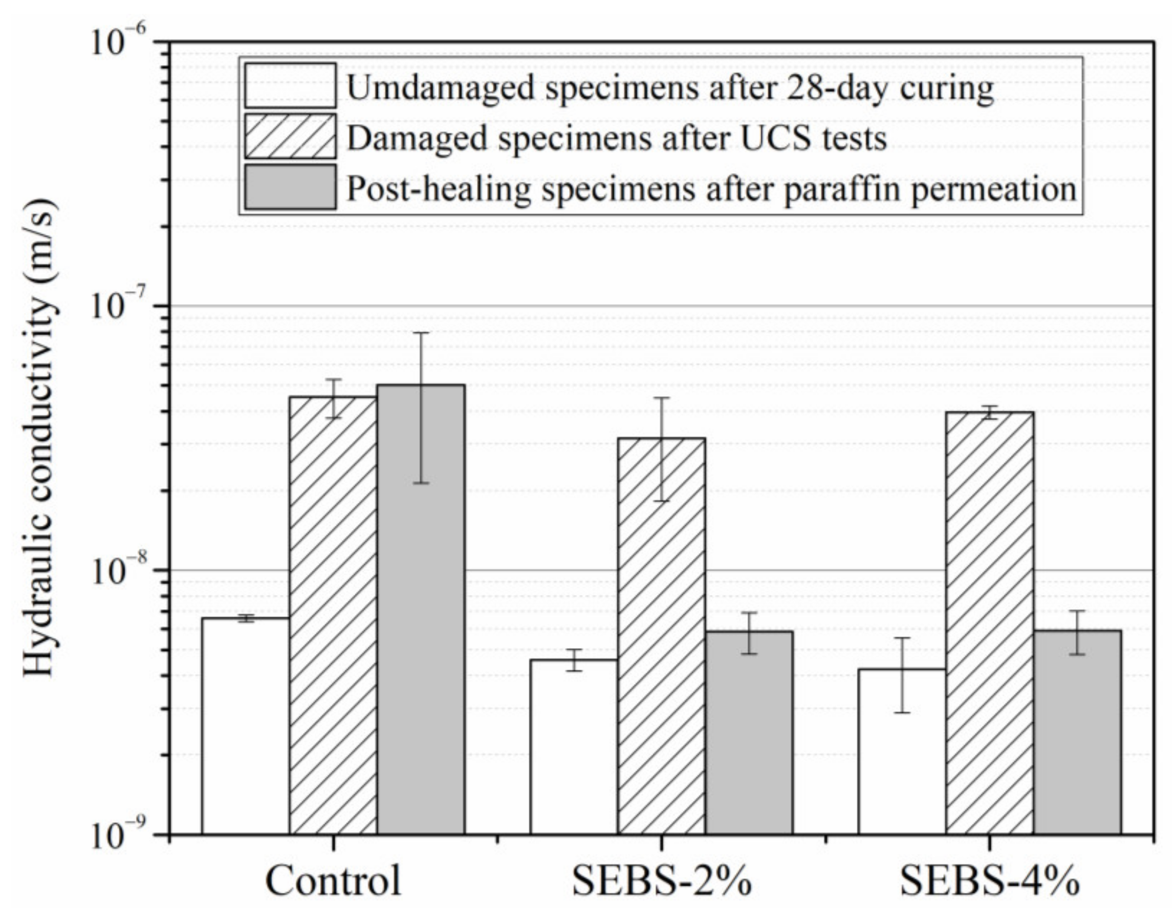
3.4. Self-Healing Performance

Figure 9 presents the comparison of the hydraulic conductivity results on the undamaged slag–cement–bentonite specimens, as well as their cracked and post-healing counterparts. The addition of SEBS had a negligible effect on the hydraulic conductivity of undamaged specimens after 28-day curing. The hydraulic conductivities of SEBS-2% and SEBS-4% were 4.6 × 10⁻⁹ m/s and 4.2 × 10⁻⁹ m/s compared with the control value of 6.6 ×10⁻⁹ m/s. This means that SEBS particles had good bonding with the cementitious matrix and no preferential channels were created due to the incorporation SEBS. In addition, the hydrophobic SEBS particles might act as a hydraulic barrier in the cementitious matrix, impeding water flow through the specimens. After the formation of cracks under the UCS frame, the damaged Control, SEBS-2% and SEBS-4% specimens had similar hydraulic conductivities of 4.5 × 10⁻⁸, 3.2 × 10⁻⁸ and 4.0 × 10⁻⁸ m/s. All of these values were higher than the recommended highest hydraulic conductivity of 1.0 × 10⁻⁸ m/s. After the permeation of liquid paraffin for six hours, the SEBS exposed to the paraffin ingress swelled and sealed the cracks, and the hydraulic conductivity decreased. In the post-healing specimens, the hydraulic conductivities of SEBS-2% and SEBS-4% decreased drastically to 5.8 × 10⁻⁹ and 5.9 × 10⁻⁹ m/s after the permeation of liquid paraffin, only slightly higher than the undamaged values. The significant recovery of the permeability of the SEBS-modified specimens exhibits good self-healing performance triggered by the ingress of organic contaminants, verifying the effective crack blockage by the swollen SEBS.
The improved mechanical and self-healing performance of the slurry wall materials can lead to more resilient and sustainable barrier systems for contaminated land containment applications, minimizing the carbon footprint and increasing the cost-effectiveness of land contamination risk management. However, a cost-effectiveness analysis of the developed novel slurry wall materials is difficult at this stage, because the cost of the adopted SEBS polymer will be variable. With the development of the scale-up of the manufacturing process and mass production techniques, the cost will decrease significantly. The RM4L project undertook various cost and economic feasibility analyses and studies about the impact of self-healing additives on the whole-life costs of infrastructure. In a Lychgate market research study, a 20% increase in initial cost was considered acceptable by the construction industry, although it was clear that a lower premium would be aimed for [28]. It is expected that the costs of polymer additives used in this study will be within the 20% margin when they are scaled up commercially.

3.5. Microstructural Analysis

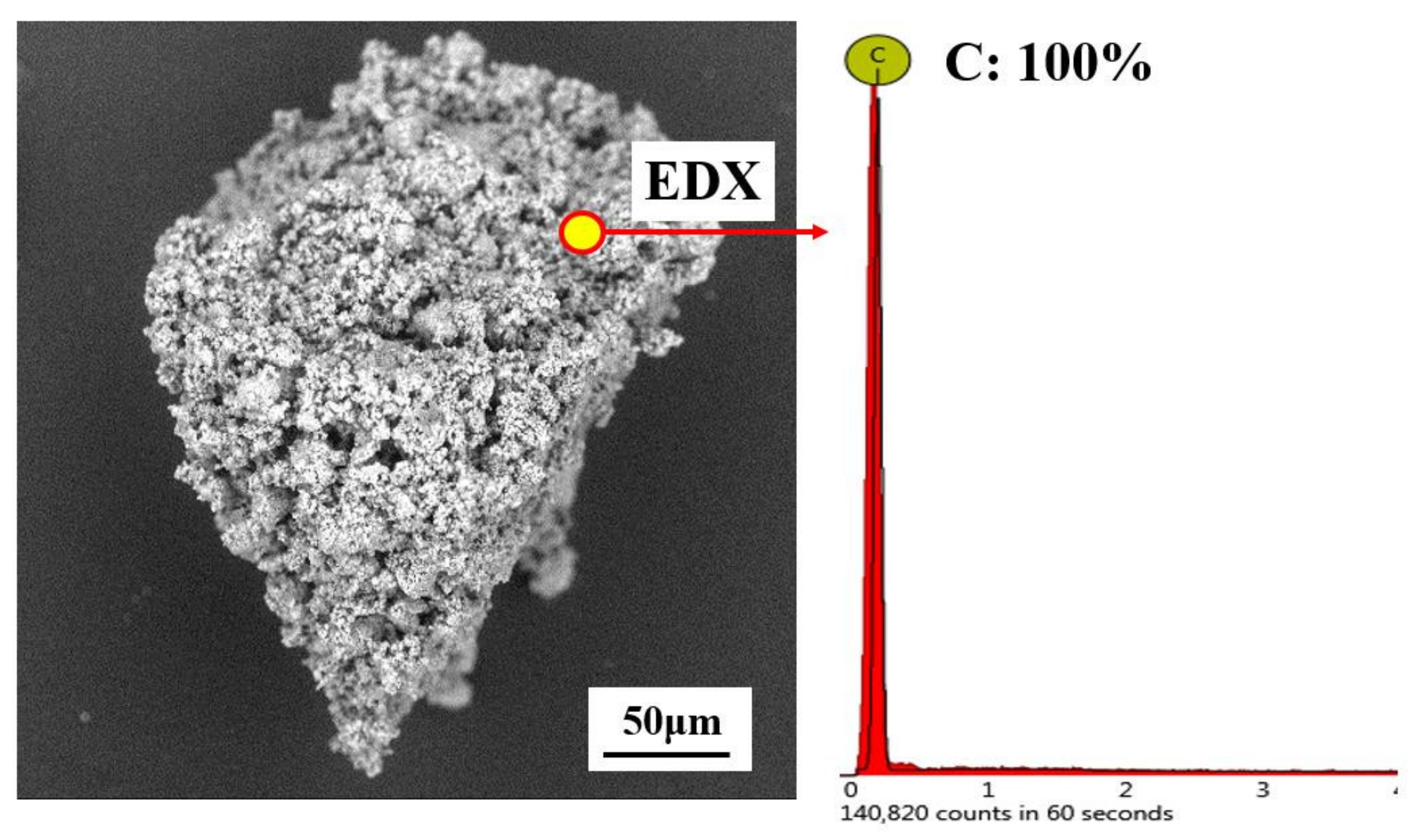
3.5.1. SEM-EDX Results

On the day of cracking, folded and dry SEBS polymer was examined on the small chips extracted from crack surfaces of SEBS-4% specimens under an SEM (Figure 10). The SEBS was found tightly embedded into the slag–cement–bentonite matrix, suggesting good bonding between the cementitious binder and the polymer despite the hydrophobic property of SEBS. The tensile strength that was mobilized during the crack development is attributed to the bonding and friction between the polymer and the cementitious particles. As a result, further opening and formation of cracks were prevented. Voids could be seen in the folded SEBS polymer, which could potentially create preferential flow channels in the matrix. However, these voids were closed pores without connection between each other, so that they failed to adversely affect the undamaged hydraulic conductivity as discussed before. Taking a closer look at the folded SEBS particle, several cement hydration products were found to adhere to the surface and within the folds. These hydration products included clusters of CSH gel, portlandite, ettringite and calcite.
EDX was also conducted to analyze the elemental composition. The tests were carried out at a point on the SEBS-4% sample, as shown in Figure 10. The EDX testing point located on the surface of the SEBS polymer, and various chemical elements, including oxygen, carbon, calcium and silicon, were detected on the SEBS surface. This confirms the precipitation of cement hydration products on the SEBS surface, indicating that the EDX point was in fact a mix of the hydrocarbon polymer and cementitious products. On the surface of SEBS, oxygen was the most-detected element, and carbon, a unique element from the polymer, accounted for the second highest proportion of the chemical composition. The EDX results confirmed the homogenous mixing of SEBS with the cementitious binder and the strong bonding between them.

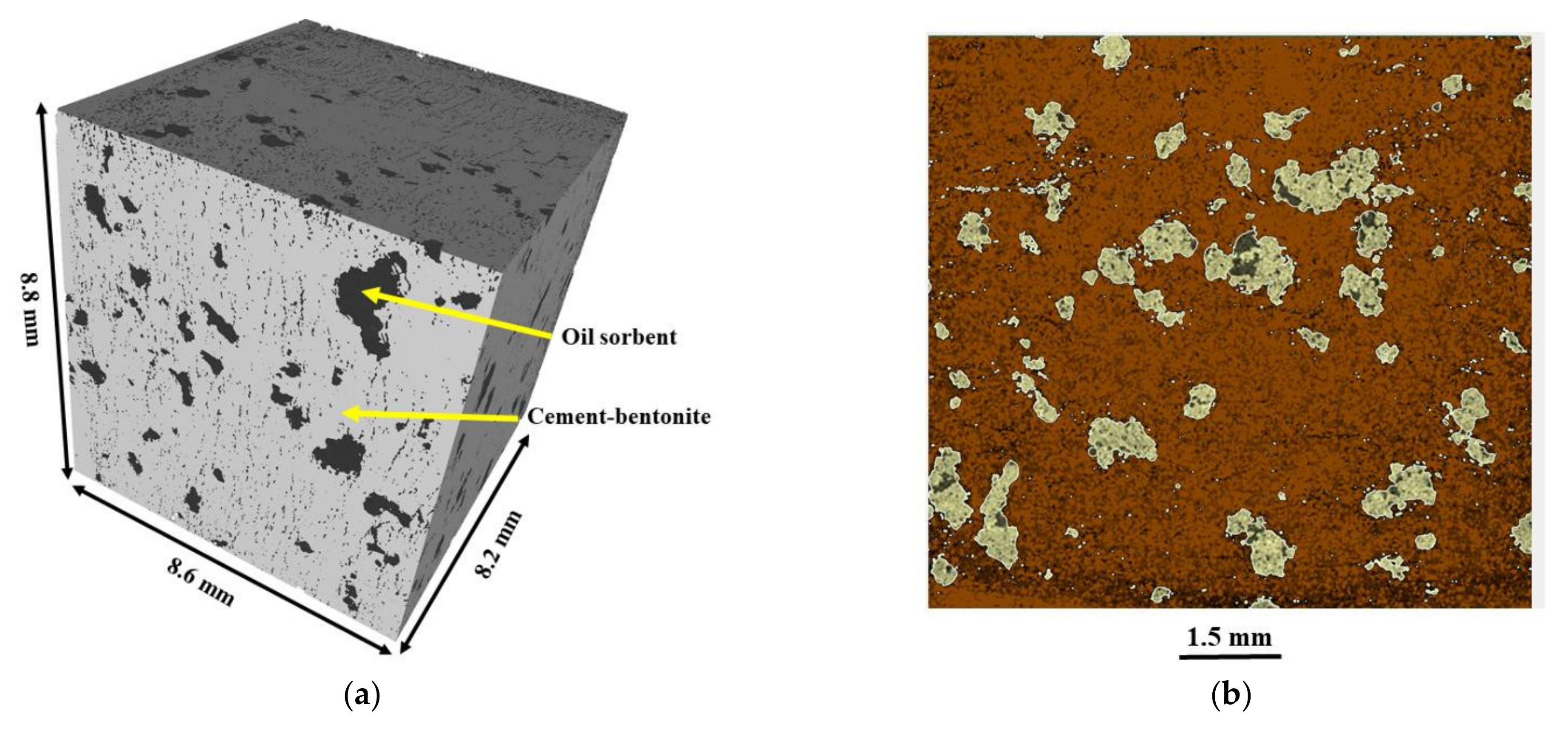
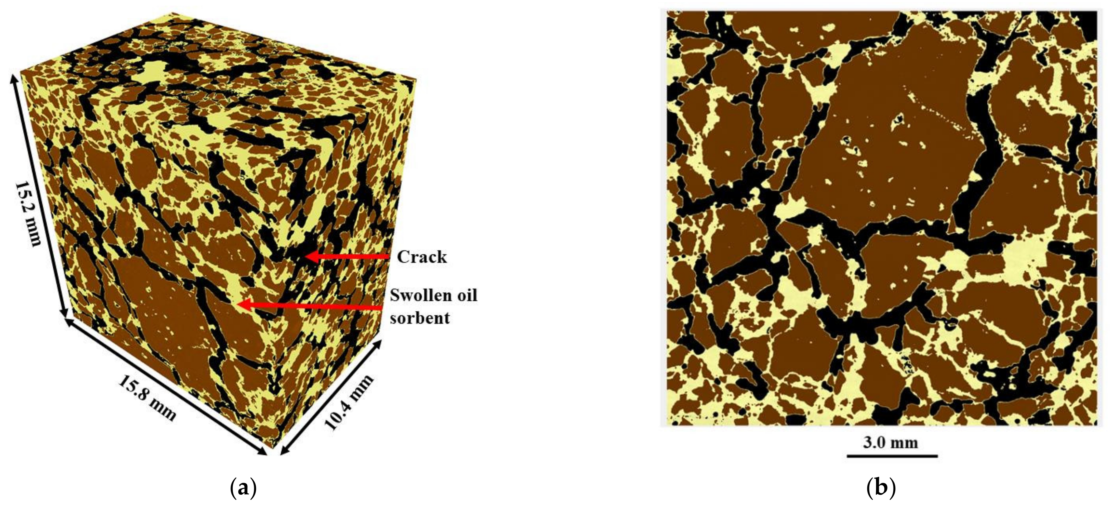
3.5.2. 3D micro-CT Results

Micro-CT analysis was carried out on an undamaged and post-healing SEBS-4% sample to investigate the 3D microstructure. Three phases could be distinguished in the undamaged samples based on the difference in density: (1) the gas phase of the voids within the dry SEBS polymer; (2) a denser solid phase of the SEBS polymer; and (3) the densest phase of the cementitious matrix. For convenience of analysis, a region of interest, 8.8 mm×8.6 mm×8.2 mm, was numerically extracted and the three phases were colored in the 2D image with black for air pores, yellow for SEBS, and brown for the slag–cement–bentonite matrix (Figure 11). In the 2D cross-section, the SEBS polymers were seen to be uniformly distributed over the slice, suggesting the good dispersion of SEBS particles during the mixing process. Pores were mostly observed within the SEBS and were not connected with each other, confirming the closed-cell porous structure of the polymers. Besides, almost no air space was observed on the periphery of the SEBS particles, which indicates good interfacial bonding with the cementitious matrix.
The second CT scan test was conducted on the post-healing sample to study the swelling and sealing performance of the SEBS. Regions of interest were extracted from the sample and the typical images are presented in Figure 12. In the reconstructed image, black cracks randomly formed throughout the sample due to desiccation. It is clear that one benefit of SEBS polymers is that they could help maintain the wholeness. Without SEBS modification, the development of a large number of wide cracks would usually disassemble the cementitious matrix. SEBS incorporated in slag–cement–bentonite function as reinforcement and binder to protect the cracked sample from disintegration. Furthermore, it is observed that the paraffin-triggered swollen SEBS could seal most cracks and cut off the flow channels. The swollen polymer was saturated with liquid paraffin, and therefore no voids were observed in the SEBS in the 2D slices, which is an obvious morphological difference from the dry and unsaturated SEBS. Figure 12c shows the extracted SEBS network saturated with liquid paraffin. This polymer network contributed significantly in maintaining the sample integrity and inhibiting the further ingress of organic liquids. In this way, the permeability was reduced and the slag–cement–bentonite samples self-healed. Generally, the observations from the micro-CT scan confirmed the even dispersion of SEBS and effective sealing of cracks, and revealed the morphological change of SEBS after absorbing liquid paraffin.

4. Conclusions

This study innovatively modified the slag–cement–bentonite material with SEBS to enhance mechanical and self-healing performance. The results demonstrate that the novel slag–cement–bentonite could provide slurry walls with resilient mechanical properties and enhanced self-healing performance. The successful development of such a resilient and sustainable slurry wall barrier has the potential to yield substantial repair and maintenance savings and to enhance the durability and serviceability of contaminated land containment applications. The main conclusions are as follows:
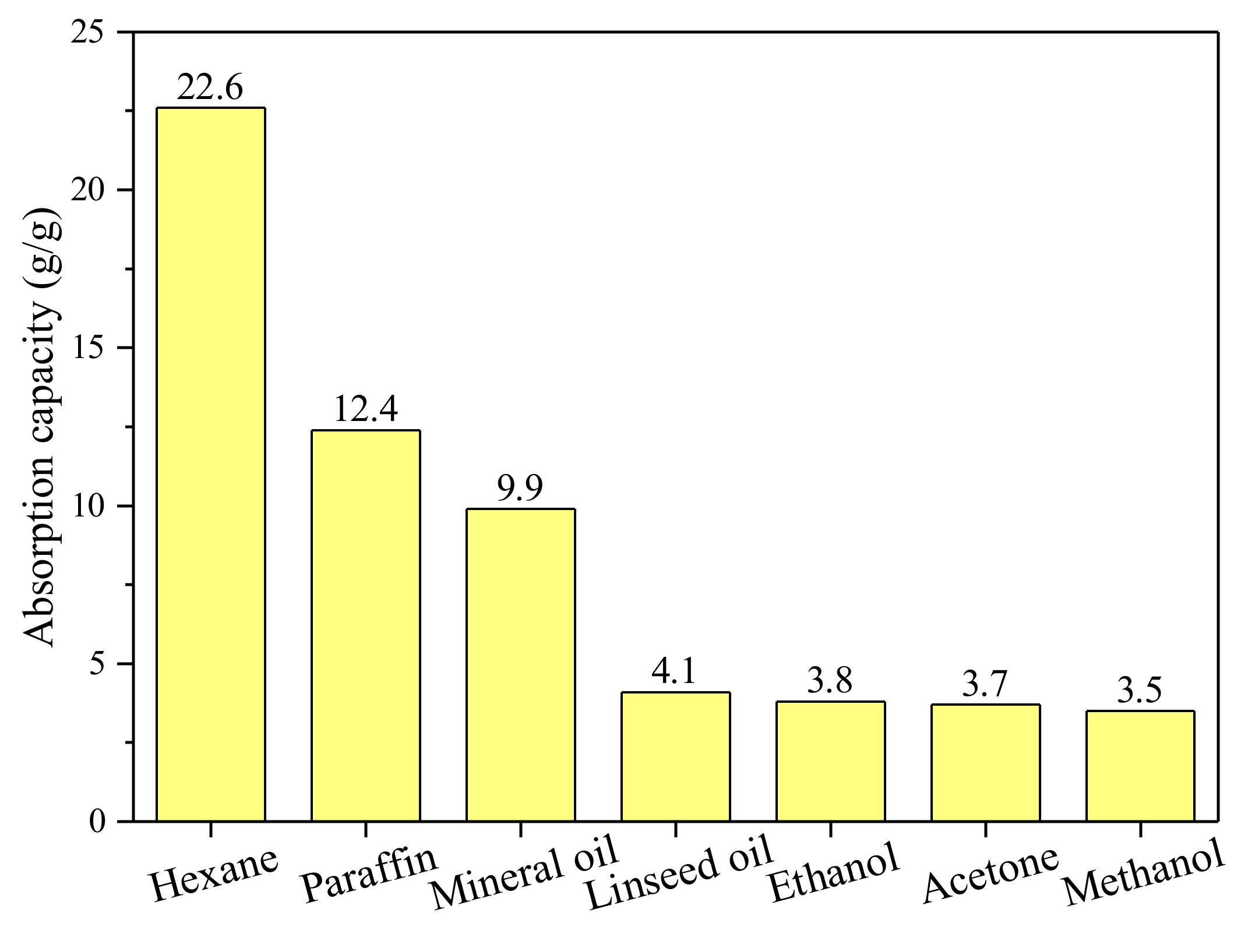
  • The absence of new peaks or frequency shifts in the FTIR spectrum indicated that the sorption process exhibited absorption (not adsorption). The SEBS polymer has a high absorption capacity at 9.8–12.4 g/g including liquid paraffin and mineral oil.
  • Although the viscosity showed a linear increase with increasing SEBS content, the viscosity values of SEBS-modified slurry were less than the suggested maximum values.
  • The increase in SEBS dosage resulted in reduced UCS and increased strain at failure, suggesting that the increased ductility is due to the addition of the deformable polymer. The increased ductility is beneficial as the slurry wall could deform to a greater extent without cracking.
  • After the permeation of liquid paraffin, the SEBS on the crack surface swelled and sealed the crack, with the post-healing hydraulic conductivity only slightly higher than the undamaged values, which exhibits good self-healing performance.
  • SEM-EDX and micro-CT scan analyses revealed strong bonding and homogeneous distribution of SEBS in the slurry. SEBS acted as a binder to protect the sample from disintegration, and the swollen SEBS particles sealed most cracks.

Author Contributions

Conceptualization, B.C. and A.A.-T.; data curation, Y.Z.; formal analysis, B.C.; funding acquisition, B.C., Y.Z. and A.A.-T.; methodology, Y.Z.; writing—original draft, B.C.; writing—review and editing, A.A.-T. All authors have read and agreed to the published version of the manuscript.

Funding

This research was funded by the EPSRC program grant Resilient Materials for Life (RM4L) (EP/P02081X/1), the Youth Program of National Natural Science Foundation of China (42107220) and the Shanghai Sailing Program (21YF1449200).

Institutional Review Board Statement

Not applicable.

Informed Consent Statement

Not applicable.

Data Availability Statement

All data, models and code generated or used during the study appear in the study.

Conflicts of Interest

The authors declare no conflict of interest.

References

  1. Jefferis, S.A. The origins of the slurry trench cut-off and a review of cement-bentonite cut-off walls in the U.K. In Proceedings of the International Containment Technology Conference and Exhibition, St. Petersburg, FL, USA, 9–12 February 1997; pp. 52–70. [Google Scholar]
  2. Hodge, V.; Robinson, T.; Spooner, P.; Wetzel, R.; Spooner, C.; Furman, C.; Tokarski, E.; Hunt, G. Slurry Trench Construction for Pollution Migration Control; U.S. Department of Energy Office of Scientific and Technical Information: Oak Ridge, TN, USA, 1985.
  3. Garvin, S.L.; Hayles, C.S. The chemical compatibility of cement–bentonite cut-off wall material. Constr. Build. Mater. 1999, 13, 329–341. [Google Scholar] [CrossRef]
  4. Jefferis, S. Cement-Bentonite Slurry Systems. In Grouting and Deep Mixing 2012, Proceedings of the Fourth International Conference on Grouting and Deep Mixing, New Orleans, LA, USA, 15–18 February 2012; ASCE: Reston, VA, USA, 2012; pp. 1–24. [Google Scholar]
  5. Alzayani, N.J.; Royal, A.C.D.; Ghataora, G.S.; Jefferson, I. Cement-bentonite in comparison with other cemented materials. Environ. Geotech. 2017, 4, 353–372. [Google Scholar] [CrossRef] [Green Version]
  6. Joshi, K.; Kechavarzi, C.; Sutherland, K.; Ng, M.Y.A.; Soga, K.; Tedd, P. Laboratory and In Situ Tests for Long-Term Hydraulic Conductivity of a Cement-Bentonite Cutoff Wall. J. Geotech. Geoenviron. Eng. 2010, 136, 562–572. [Google Scholar] [CrossRef]
  7. Royal, A.C.D.; Opukumo, A.W.; Qadr, C.S.; Perkins, L.M.; Walenna, M.A. Deformation and Compression Behaviour of a Cement–Bentonite Slurry for Groundwater Control Applications. Geotech. Geol. Eng. 2018, 36, 835–853. [Google Scholar] [CrossRef] [Green Version]
  8. Opdyke, S.M.; Evans, J.C. Slag-Cement-Bentonite Slurry Walls. J. Geotech. Geoenviron. Eng. 2005, 131, 673–681. [Google Scholar] [CrossRef]
  9. Cermak, J.; Evans, J.; Tamaro, G.J. Evaluation of Soil-Cement-Bentonite Wall Performance—Effects of Backfill Shrinkage. In Grouting and Deep Mixing 2012, Proceedings of the Fourth International Conference on Grouting and Deep Mixing, New Orleans, LA, USA, 15–18 February 2012; ASCE: Reston, VA, USA, 2012; pp. 502–511. [Google Scholar]
  10. Nejad, B.G.; Osborne, T.; Carter, J.P. Forensic Investigation of a Slurry Wall Failure: A Case Study. In Grouting 2017, Proceedings of the Fifth International Conference on Grouting, Honolulu, HI, USA, 9–12 July 2017; ASCE: Reston, VA, USA, 2017; pp. 513–522. [Google Scholar]
  11. Cao, B.; Chen, J.; Al-Tabbaa, A. Crack-resistant cement–bentonite cut-off wall materials incorporating superabsorbent polymers. Can. Geotech. J. 2021, 58, 800–810. [Google Scholar] [CrossRef]
  12. Alzayani, N.J. Impact of Undrained Deformation on the Hydraulic Conductivity of Cement-Bentonite Barrier Material. Ph.D. Thesis, University of Birmingham, Birmingham, UK, 2019. [Google Scholar]
  13. Al-Tabbaa, A.; Harbottle, M.J. Self-healing materials and structures for geotechnical and geo-environmental applications. Geotech. Eng. Infrastruct. Dev. 2015, 589–594. [Google Scholar]
  14. Mangadlao, J.D.; Cao, P.; Advincula, R.C. Smart cements and cement additives for oil and gas operations. J. Pet. Sci. Eng. 2015, 129, 63–76. [Google Scholar] [CrossRef]
  15. Lu, Z.; Kong, X.; Yang, R.; Zhang, Y.; Jiang, L.; Wang, Z.; Wang, Q.; Liu, W.; Zeng, M.; Zhou, S.; et al. Oil swellable polymer modified cement paste: Expansion and crack healing upon oil absorption. Constr. Build. Mater. 2016, 114, 98–108. [Google Scholar] [CrossRef]
  16. Allen, N.S.; Edge, M.; Wilkinson, A.; Liauw, C.M.; Mourelatou, D.; Barrio, J.; Martínez-Zaporta, M.A. Degradation and stabilisation of styrene–ethylene–butadiene–styrene (SEBS) block copolymer. Polym. Degrad. Stab. 2000, 71, 113–122. [Google Scholar] [CrossRef]
  17. ASTM. D4219-08; Standard Test Method for Unconfined Compressive Strength Index of Chemical-Grouted Soils. ASTM International: West Conshohocken, PA, USA, 2008.
  18. ASTM. D5084-16; Standard Test Methods for Measurement of Hydraulic Conductivity of Saturated Porous Materials Using a Flexible Wall Permeameter. ASTM International: West Conshohocken, PA, USA, 2016.
  19. Zhou, X.-M.; Chuai, C.-Z. Synthesis and characterization of a novel high-oil-absorbing resin. J. Appl. Polym. Sci. 2010, 115, 3321–3325. [Google Scholar] [CrossRef]
  20. Luengo, C.; Allen, N.S.; Edge, M.; Wilkinson, A.; Parellada, M.D.; Barrio, J.A.; Santa, V.R. Photo-oxidative degradation mechanisms in styrene–ethylene–butadiene–styrene (SEBS) triblock copolymer. Polym. Degrad. Stab. 2006, 91, 947–956. [Google Scholar] [CrossRef]
  21. Senna, M.M.H.; Abdel-Moneam, Y.K.; Hussein, Y.A.; Alarifi, A. Effects of electron beam irradiation on the structure–property behavior of blends based on low density polyethylene and styrene-ethylene-butylene-styrene-block copolymers. J. Appl. Polym. Sci. 2012, 125, 2384–2393. [Google Scholar] [CrossRef]
  22. Chi, W.S.; Hwang, S.; Lee, S.-J.; Park, S.; Bae, Y.-S.; Ryu, D.Y.; Kim, J.H.; Kim, J. Mixed matrix membranes consisting of SEBS block copolymers and size-controlled ZIF-8 nanoparticles for CO2 capture. J. Membr. Sci. 2015, 495, 479–488. [Google Scholar] [CrossRef]
  23. Klaus, E.E.; Perez, J.M. Thermal Stability Characteristics of Some Mineral Oil and Hydrocarbon Hydraulic Fluids and Lubricants. ASLE Trans. 1976, 10, 38–47. [Google Scholar] [CrossRef]
  24. Faridmehr, I.; YazdaniPour, M.R.; Jokar, M.J.; Ozbakkaloglu, T. Construction and Monitoring of Cement/Bentonite Cutoff Walls: Case Study of Karkheh Dam, Iran. Studia Geotech. Mech. 2019, 41, 184–199. [Google Scholar] [CrossRef] [Green Version]
  25. Ryan, C.; Day, S. Performance Evaluation of Cement-Bentonite Slurry Wall Mix Design; US EPA: Washington, DC, USA, 1986.
  26. Didier, P.; Léger, R.; Otazaghine, B.; Ienny, P. Hyperelastic behavior of modified sepiolite/SEBS thermoplastic elastomers. J. Mater. Sci. 2017, 52, 7591–7604. [Google Scholar]
  27. Hamoush, S.; Abu-Lebdeh, T.; Cummins, T. Deflection behavior of concrete beams reinforced with PVA micro-fibers. Constr. Build. Mater. 2010, 24, 2285–2293. [Google Scholar] [CrossRef]
  28. Gardner, D.; Lark, R.; Jefferson, T.; Davies, R. A survey on problems encountered in current concrete construction and the potential benefits of self-healing cementitious materials. Case Stud. Constr. Mater. 2018, 8, 238–247. [Google Scholar] [CrossRef]
Figure 1. (a) Chemical structure and (b) schematic polymer network of the styrene–ethylene/butylene–styrene (SEBS) polymer used in this study.
Sustainability 14 02093 g001
Figure 2. Typical images of an SEBS particle under an SEM with EDX analysis.
Sustainability 14 02093 g002
Figure 3. The sorption capacity of the SEBS in different organic liquids.
Sustainability 14 02093 g003
Figure 4. FTIR spectra of the SEBS before and after the absorption of liquid paraffin.
Sustainability 14 02093 g004
Figure 5. The TGA results of (a) mass loss and (b) differential thermogravimetry (DTG) curves of the SEBS before and after the absorption of liquid paraffin.
Sustainability 14 02093 g005
Figure 6. Variations of (a) plastic viscosity and (b) yield stress of slag–cement–bentonite mixes with increasing SEBS dosage.
Sustainability 14 02093 g006
Figure 7. The average values of (a) UCS and (b) strain at failure of slag–cement–bentonite specimens.
Sustainability 14 02093 g007
Figure 8. Typical stress–strain curves of 90-day cured slag–cement–bentonite specimens.
Sustainability 14 02093 g008
Figure 9. The permeability recovery of slag–cement–bentonite specimens.
Sustainability 14 02093 g009
Figure 10. Representative SEM images and EDX results of an SEBS-4% sample.
Sustainability 14 02093 g010
Figure 11. Reconstructed (a) 3D and (b) 2D image of an undamaged SEBS-4% sample (black for air pores, yellow for SEBS, and brown for cementitious matrix).
Sustainability 14 02093 g011
Figure 12. Reconstructed (a) 3D and (b) 2D image of a post-healing SEBS-4% sample; (c) extracted swollen SEBS network (black for cracks, yellow for SEBS, and brown for cementitious matrix).
Sustainability 14 02093 g012aSustainability 14 02093 g012b
Table 1. Principal oxides of the cement, GGBS and bentonite used, as provided by the supplier.
CaO
(%)
SiO2
(%)
Al2O3
(%)
MgO
(%)
Fe2O3
(%)
Cement6520512
GGBS403512100.2
Bentonite1.0165.311.73.356.36
Table 2. Mix composition (%) of slag–cement–bentonite slurry.
Mix IDSlag–Cement–Bentonite SlurrySEBS (% by Total Slurry Weight)
BentoniteCementGGBSWater
Control5416750
SEBS-2%5416752
SEBS-4%5416754
Publisher’s Note: MDPI stays neutral with regard to jurisdictional claims in published maps and institutional affiliations.

