
LCA of Mortar with Calcined Clay and Limestone Filler in RC Column Retrofit


Abstract
:1. Introduction
2. Materials and Methods
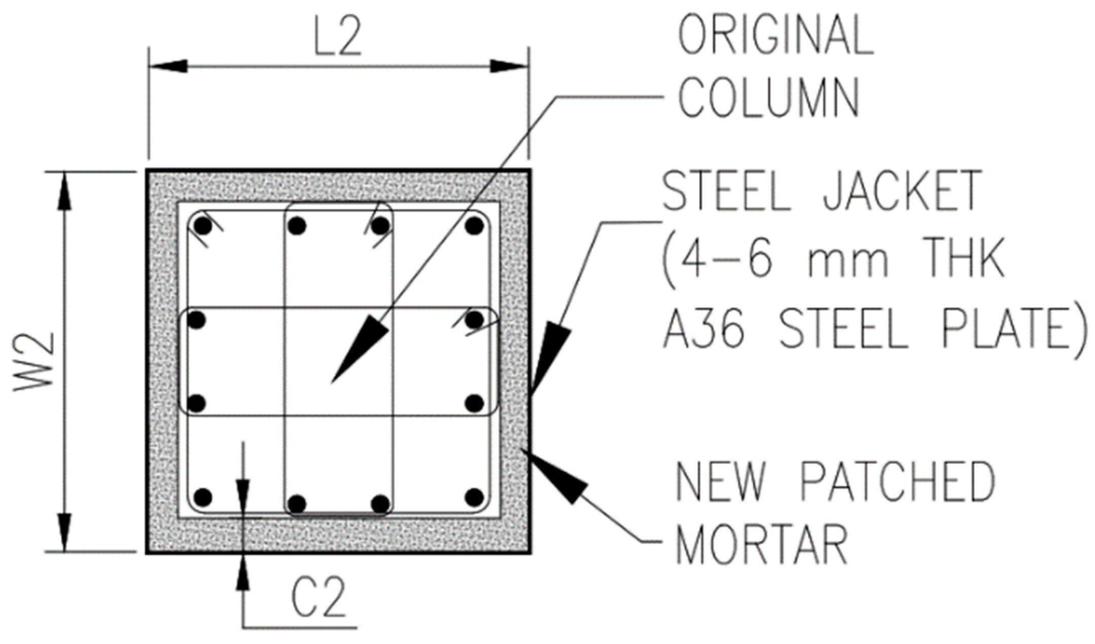
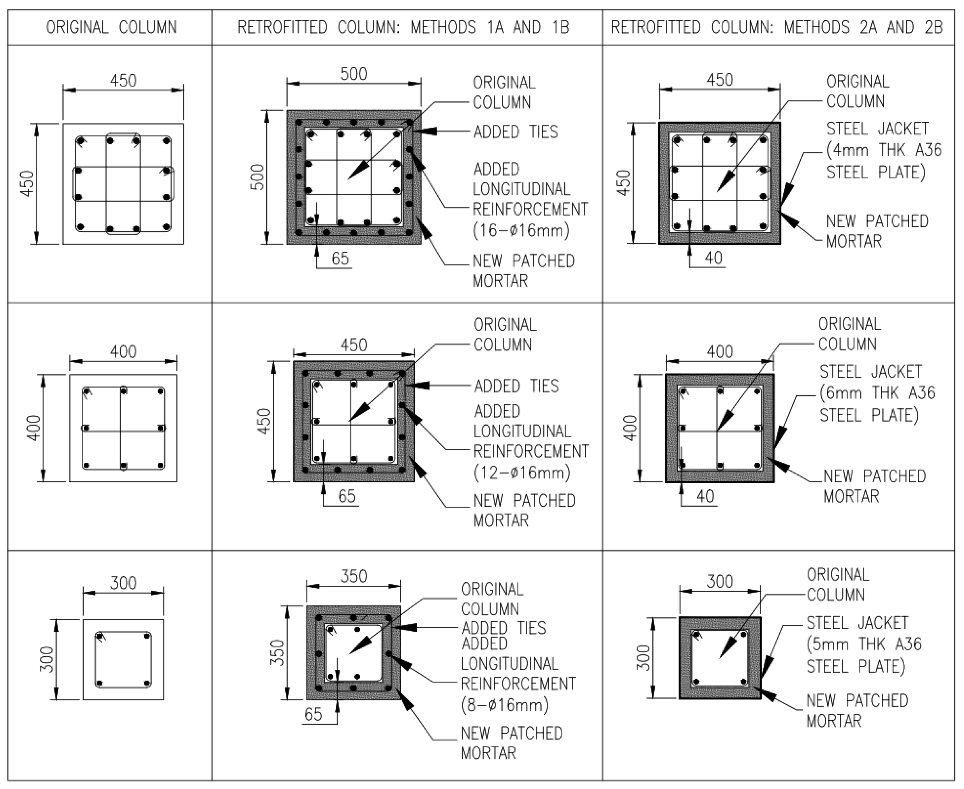
2.1. Use of Mortar with Calcined Clay and Limestone Filler for Retrofitting Works
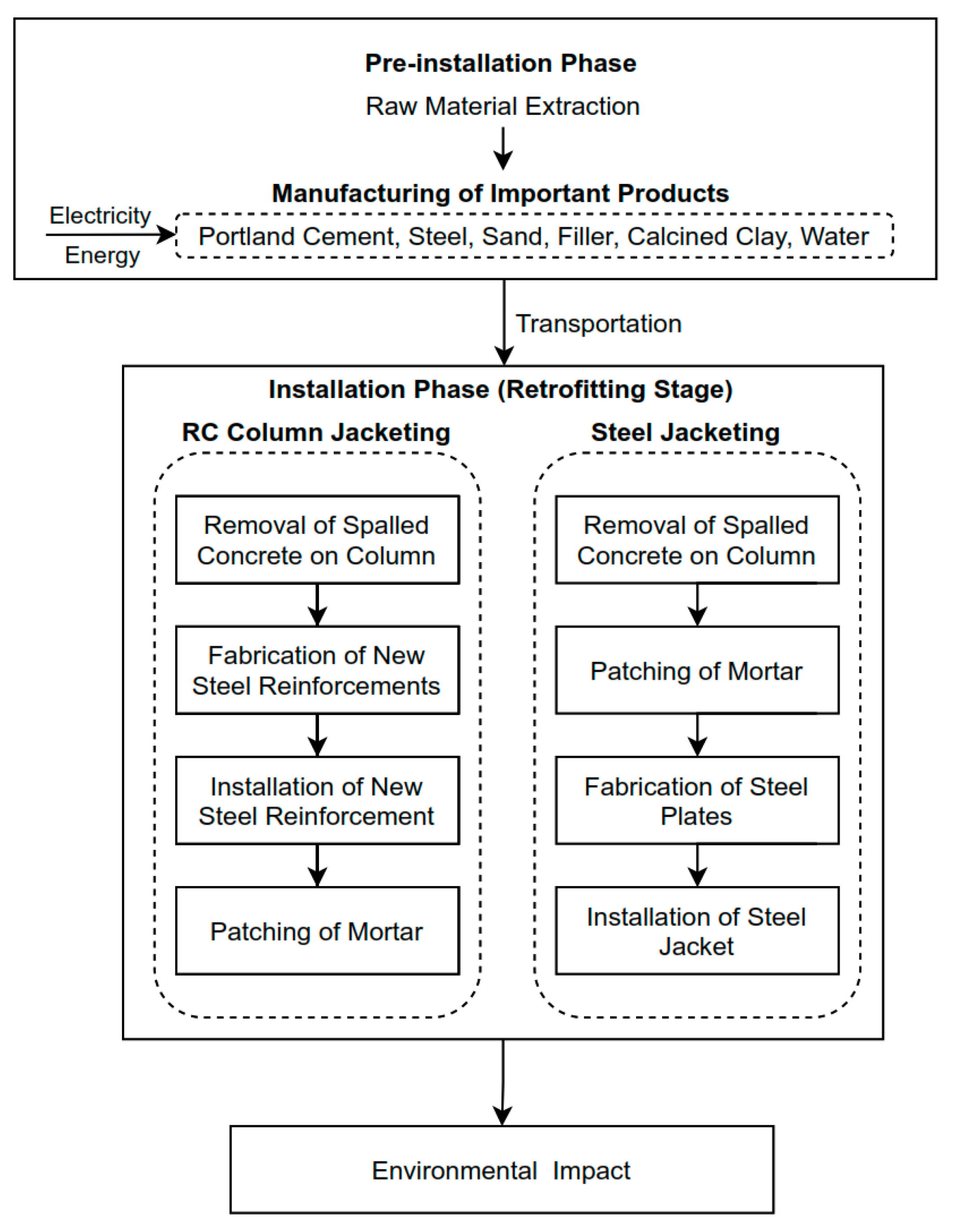
2.2. Life Cycle Assessment
2.2.1. Goal and Scope Definition
2.2.2. Functional Unit
2.2.3. System Boundary
2.2.4. Data Collection for LCI, Analysis, and Interpretation
3. Results and Discussion
3.1. Life Cycle Inventory (LCI) Analysis Phase
3.1.1. Column Design and Bill of Materials
3.1.2. Life Cycle Inventory
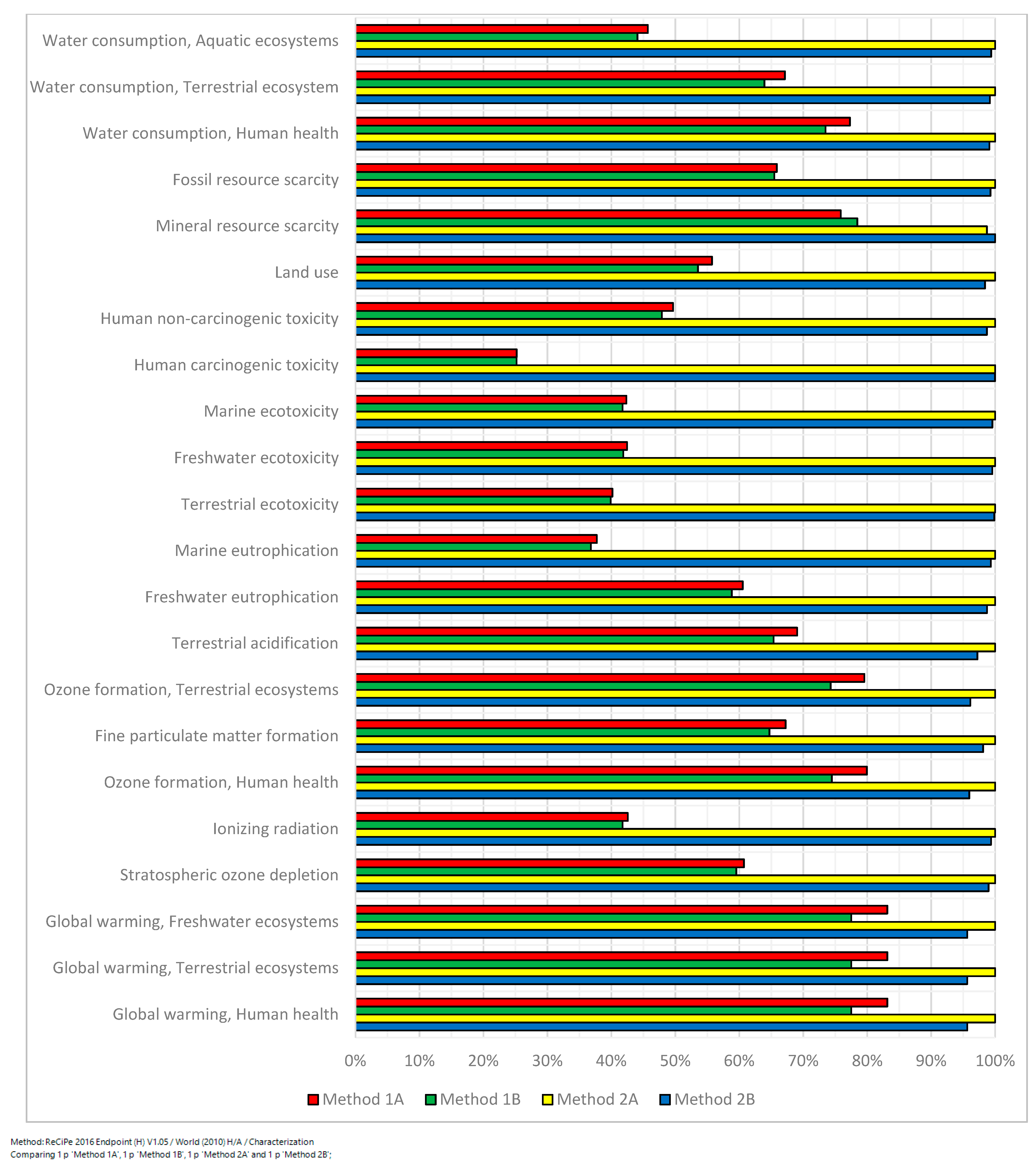
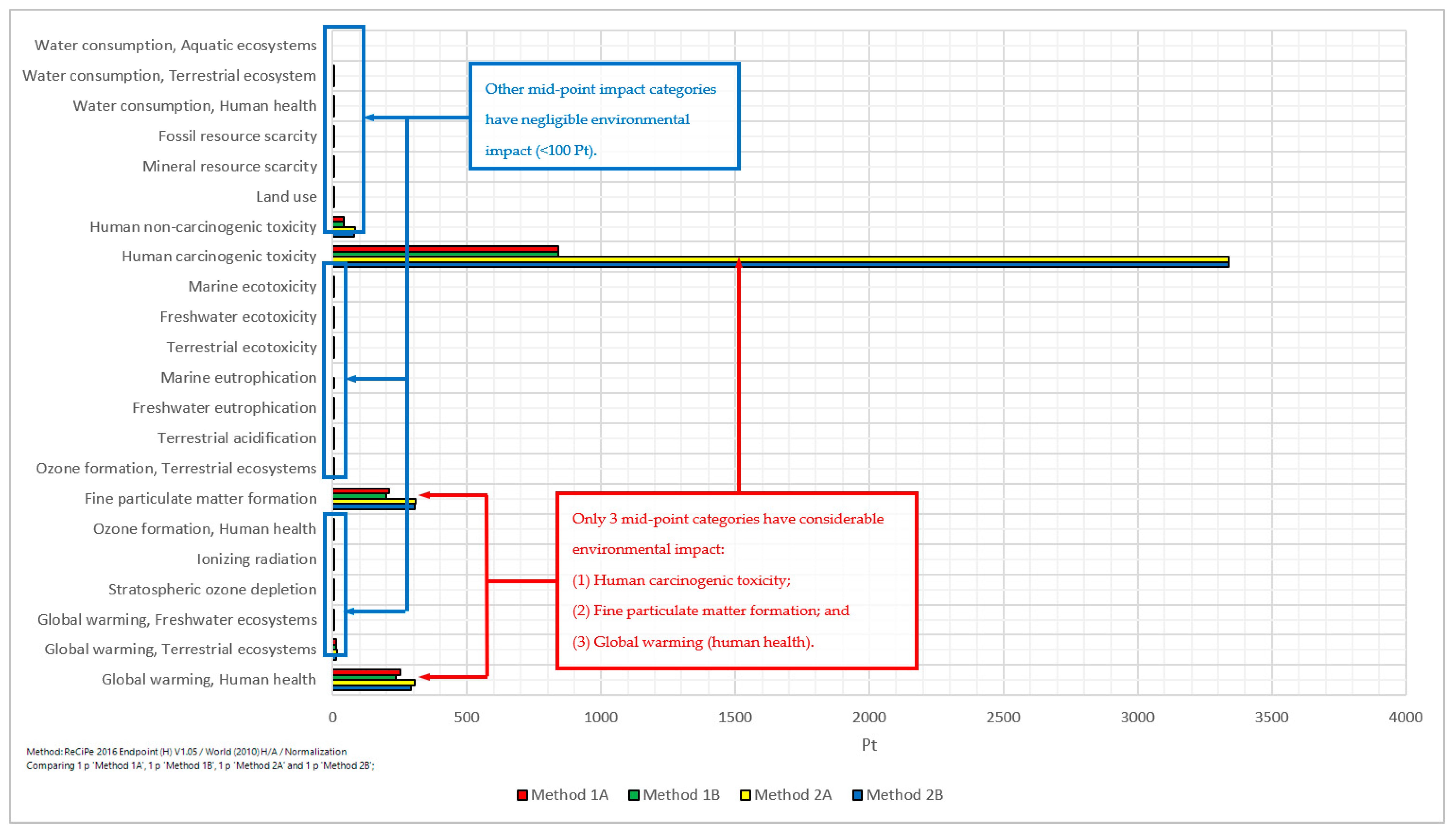
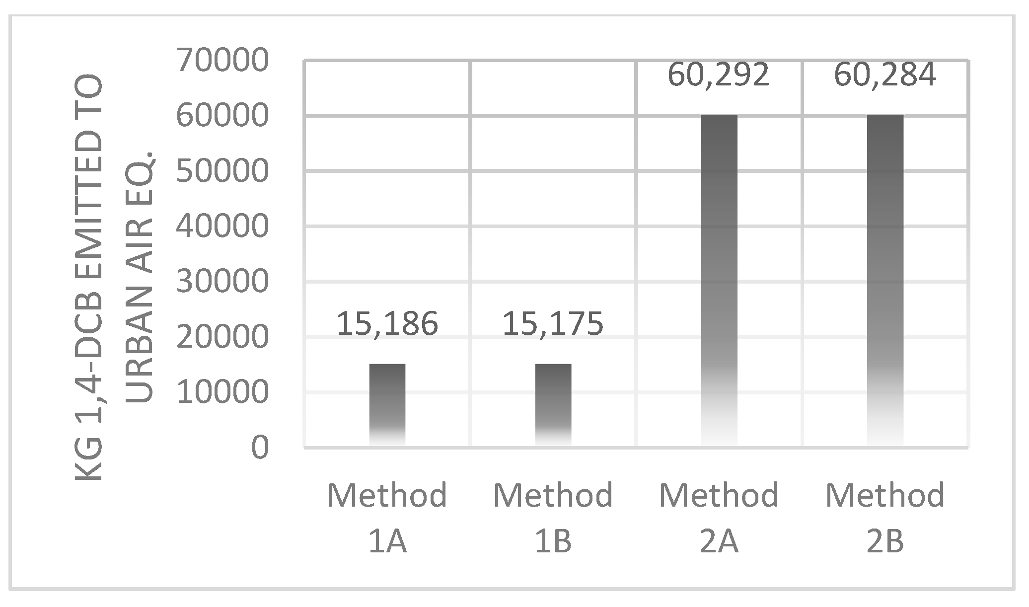
3.2. Life Cycle Impact Assessment and Interpretation
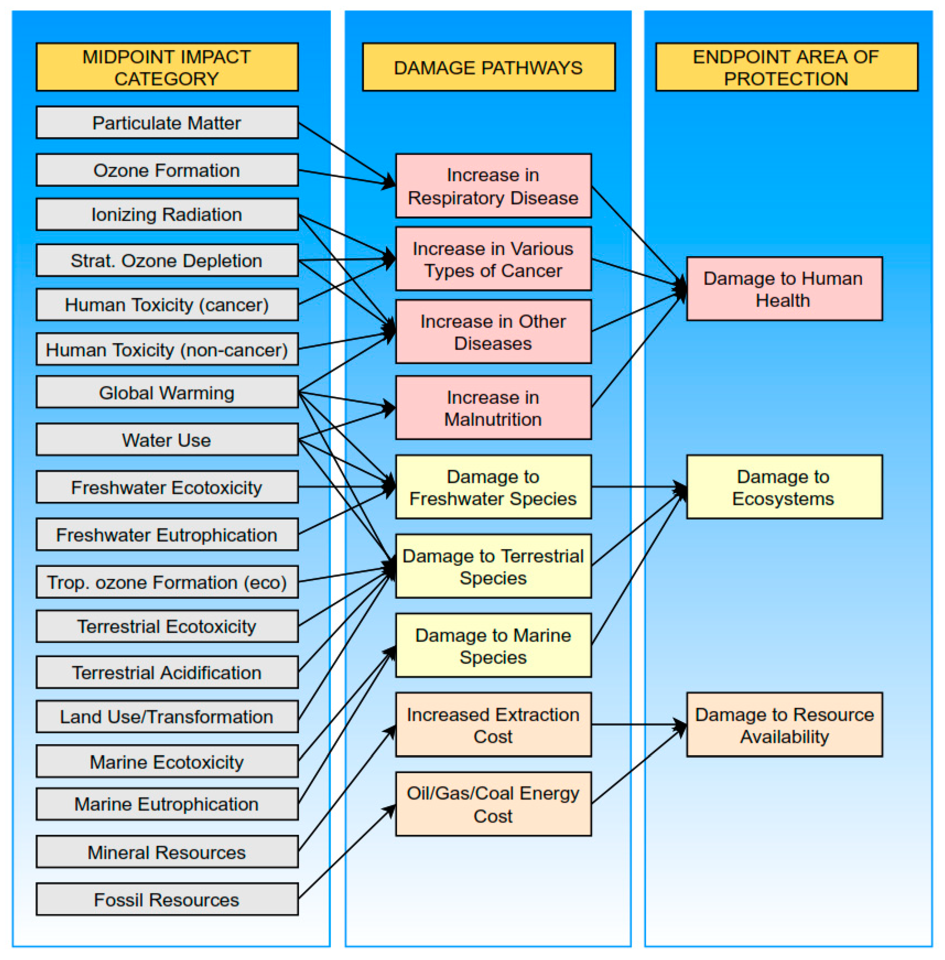
3.2.1. Impact Assessment Method
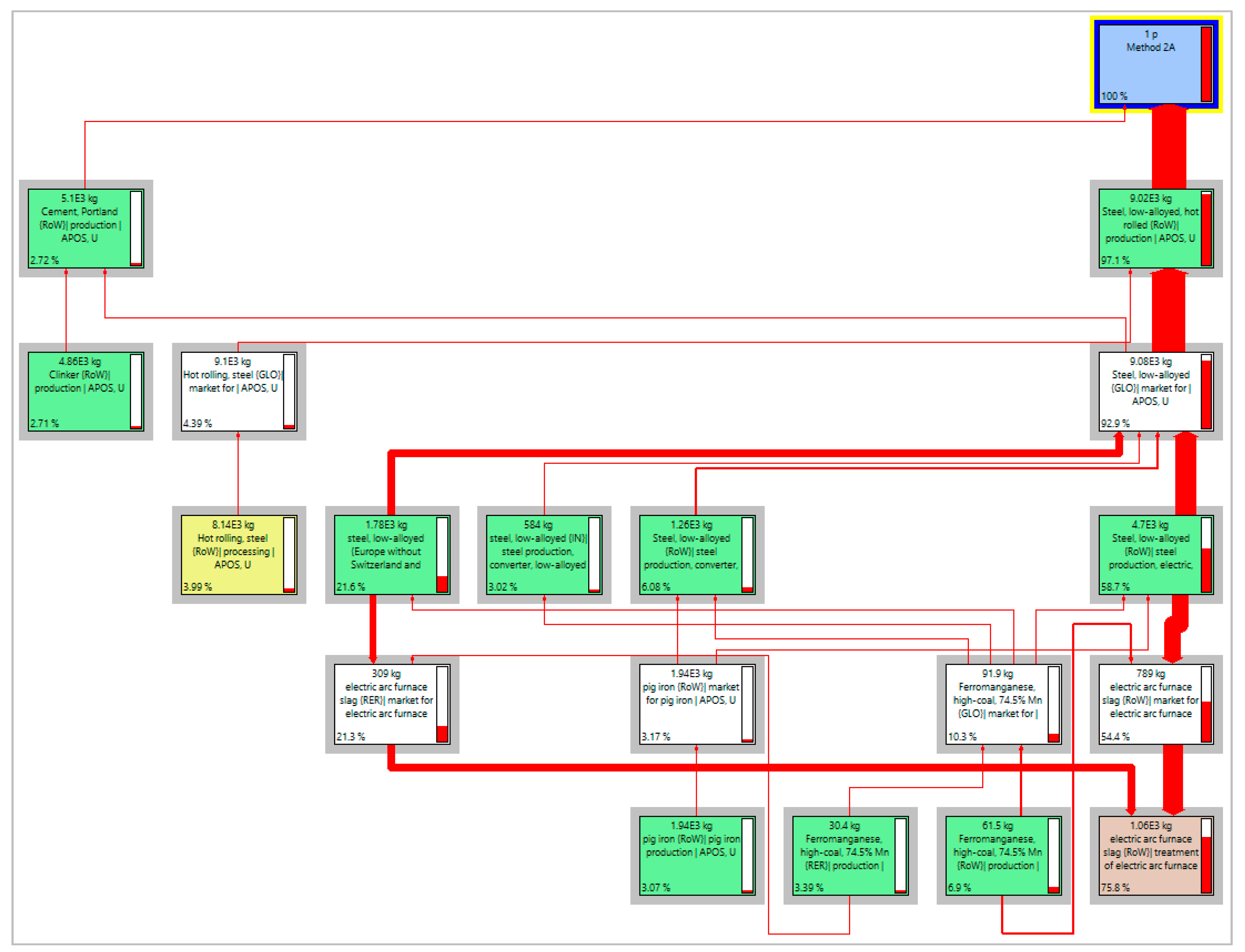
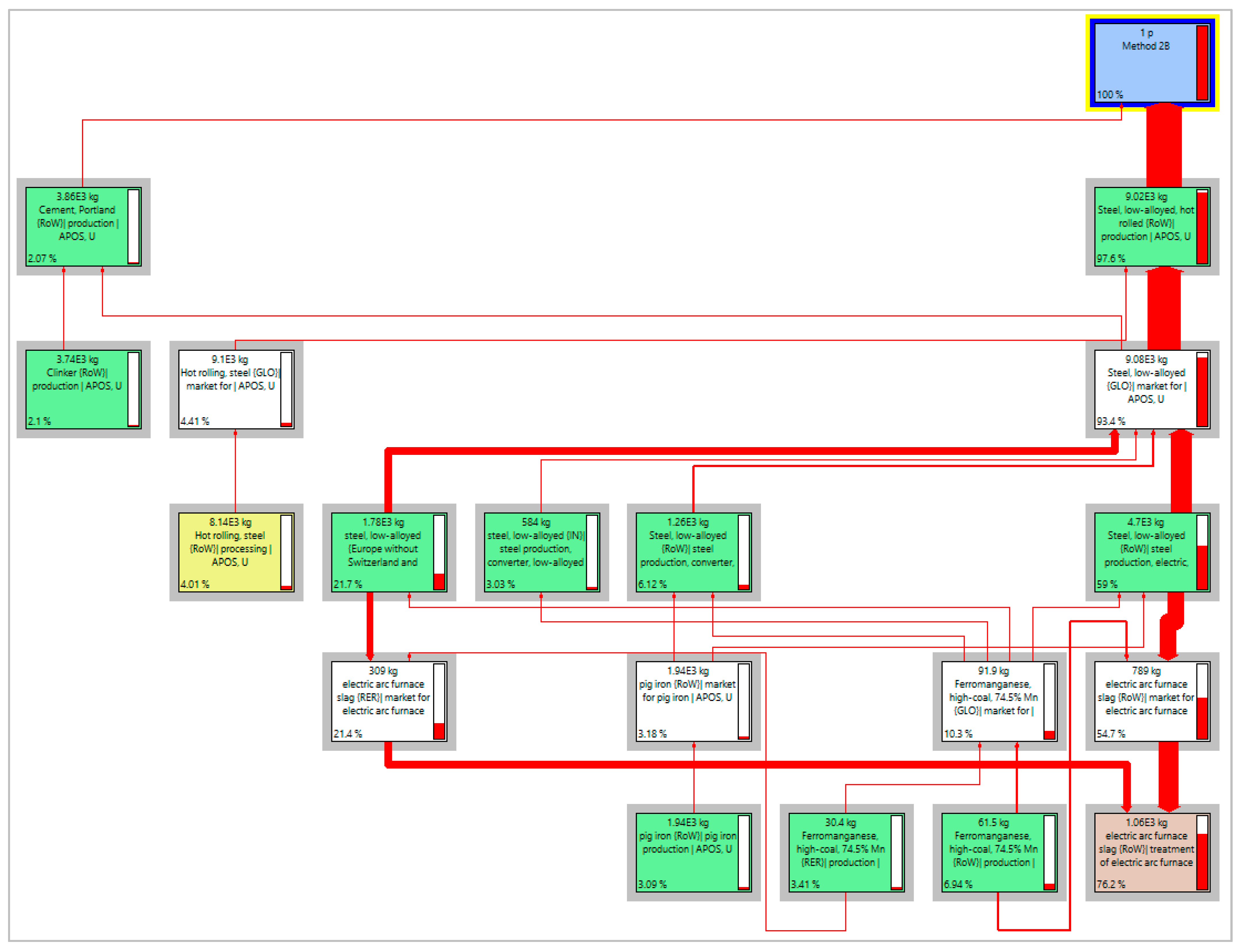
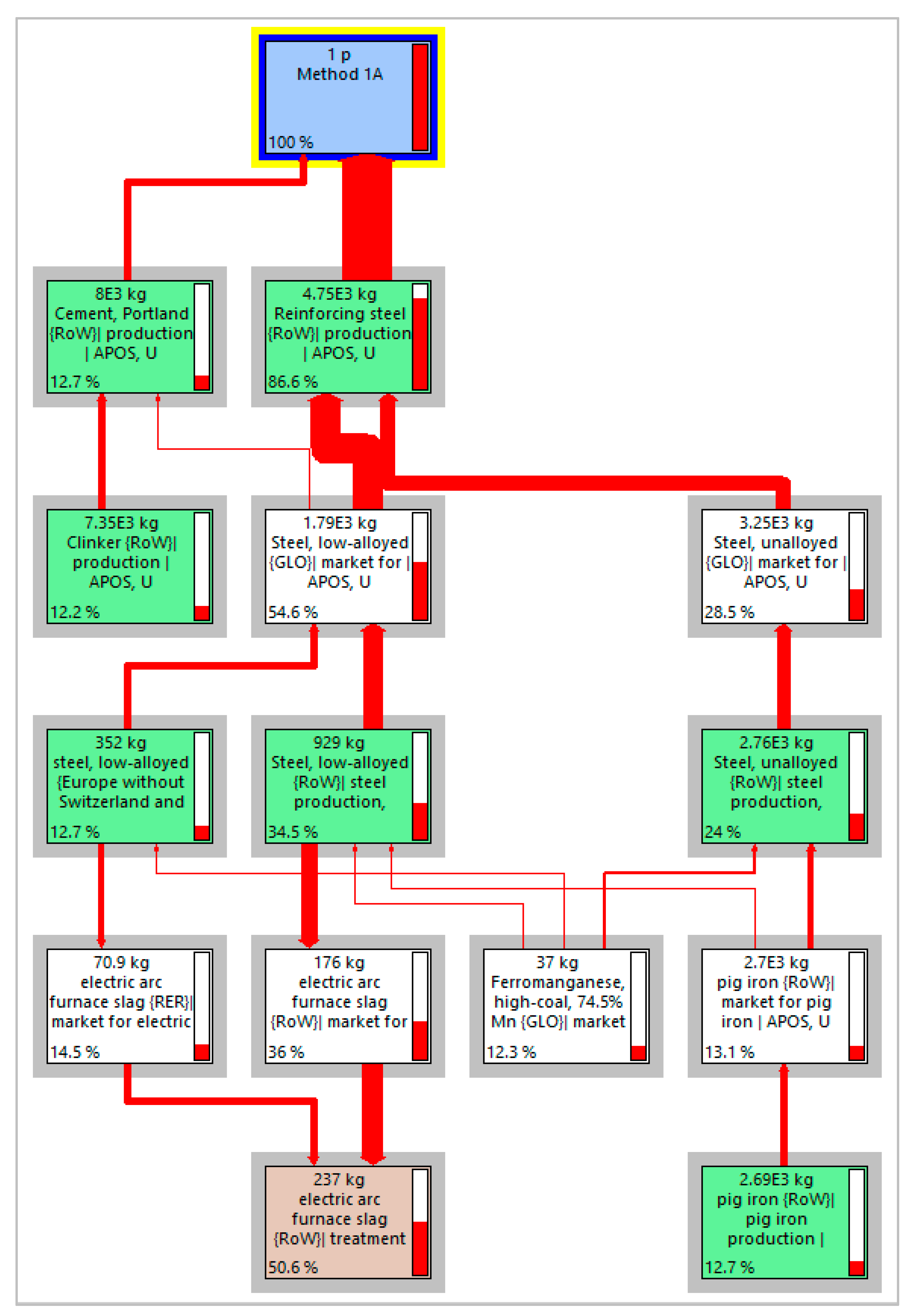
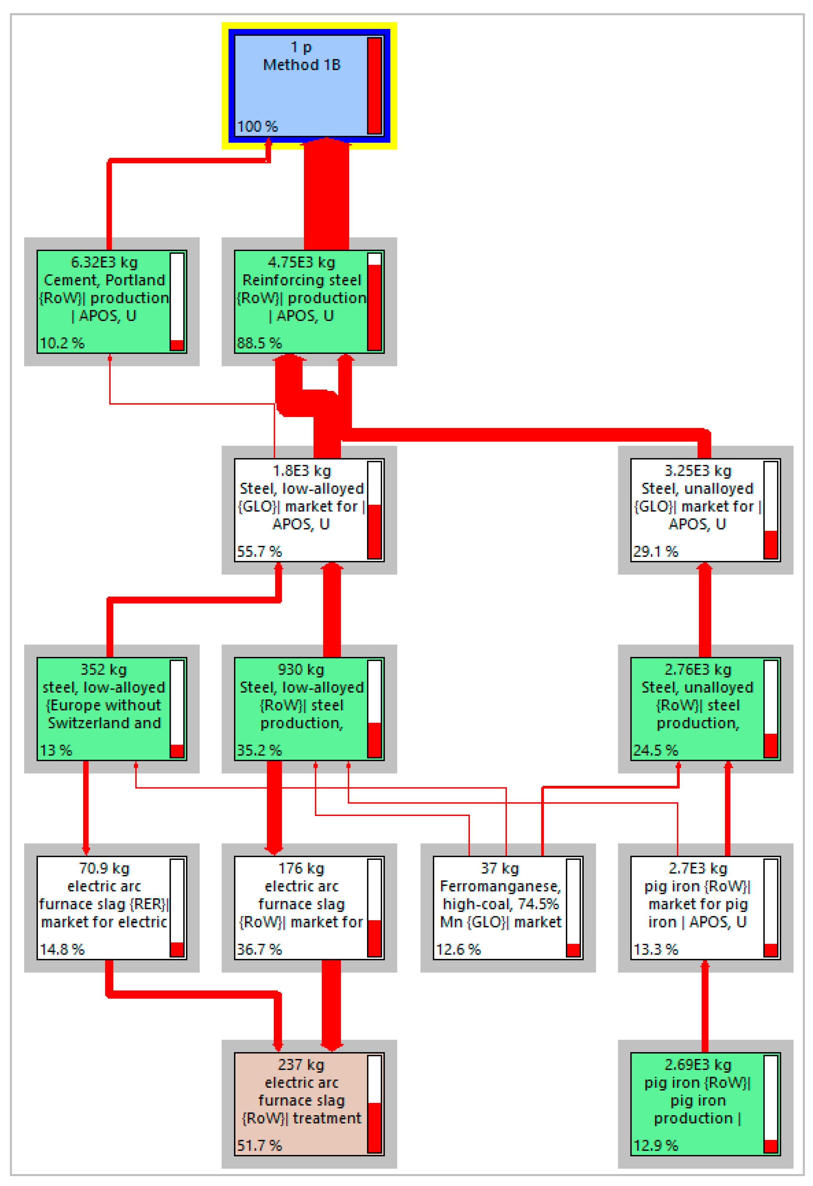
3.2.2. Process Network
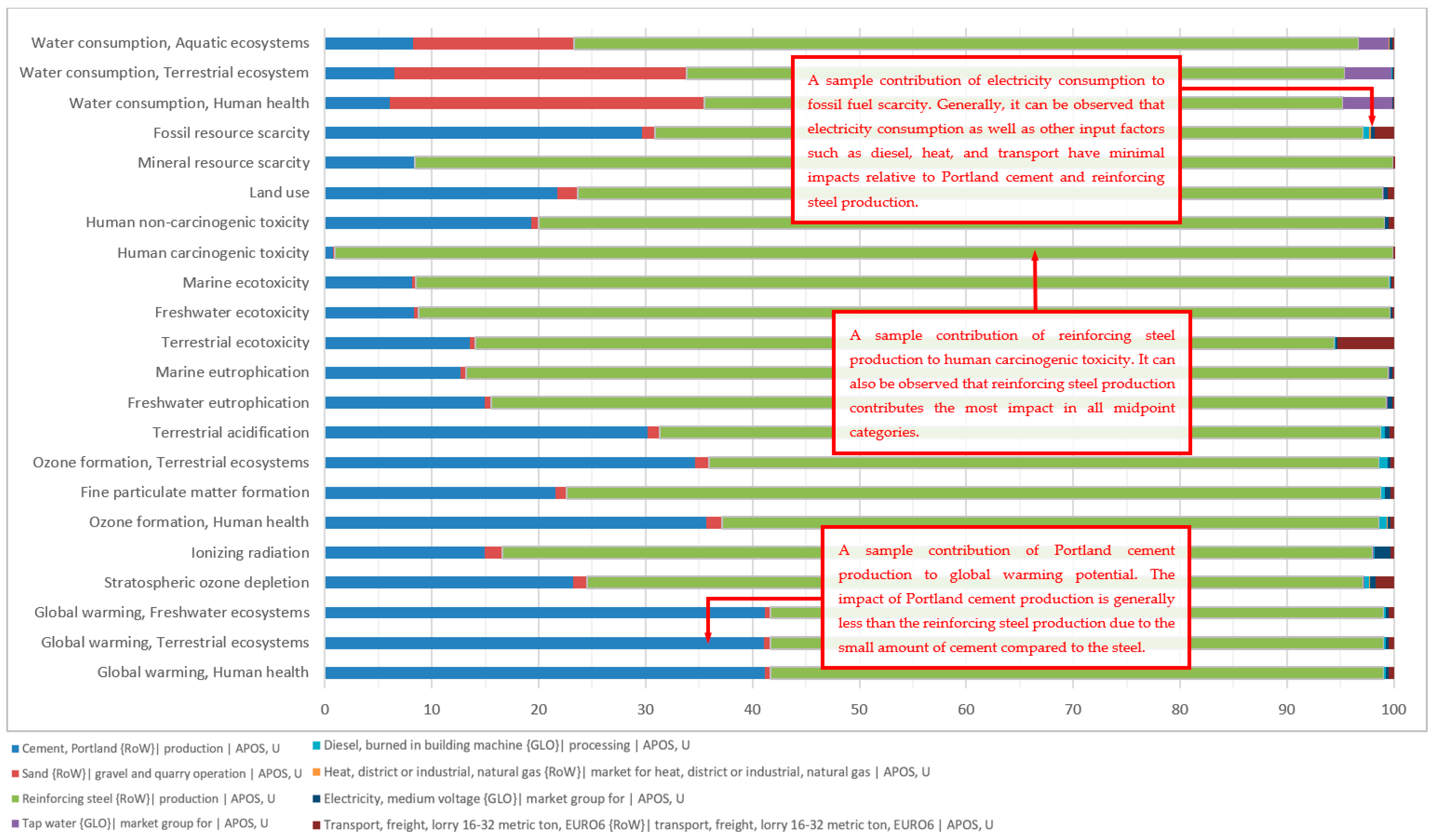
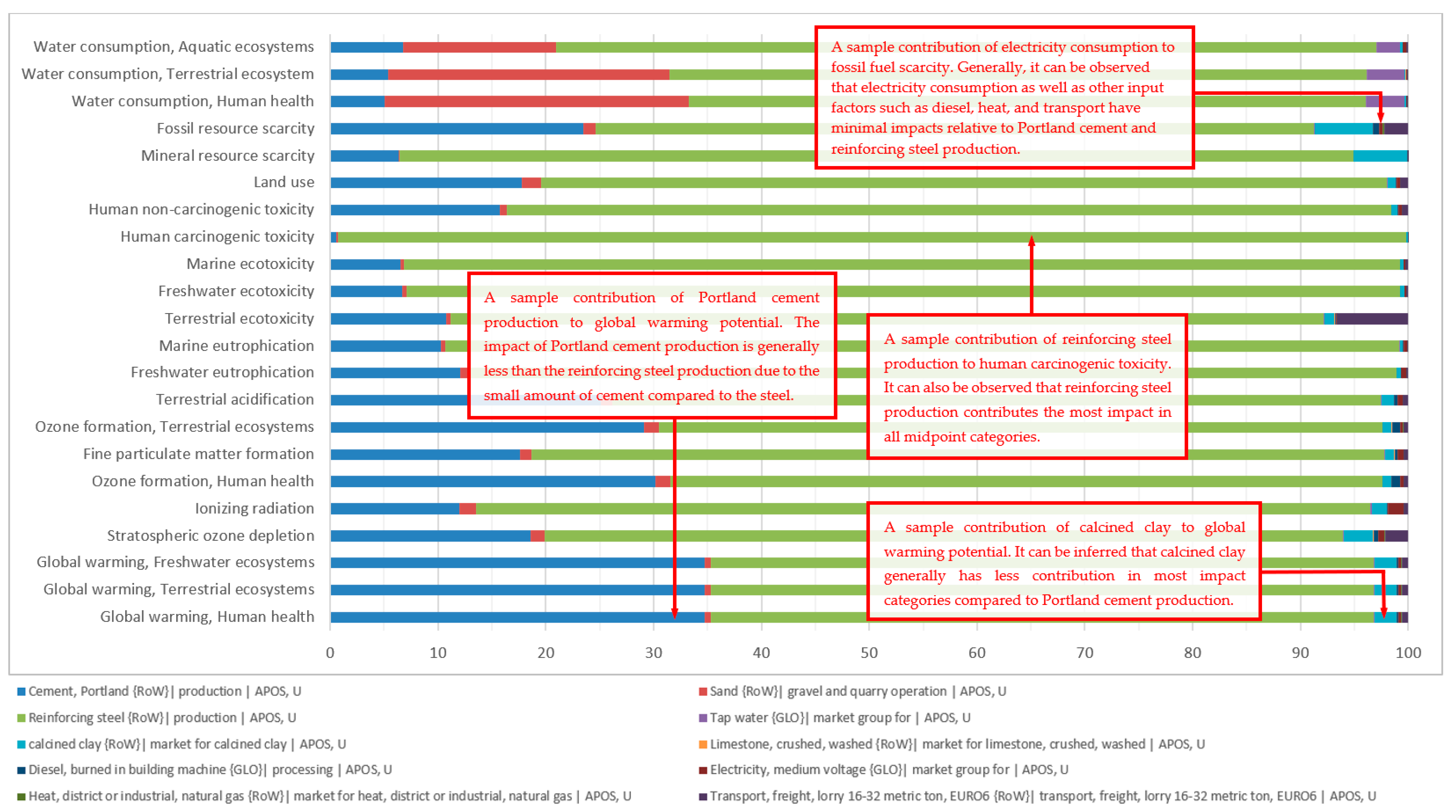
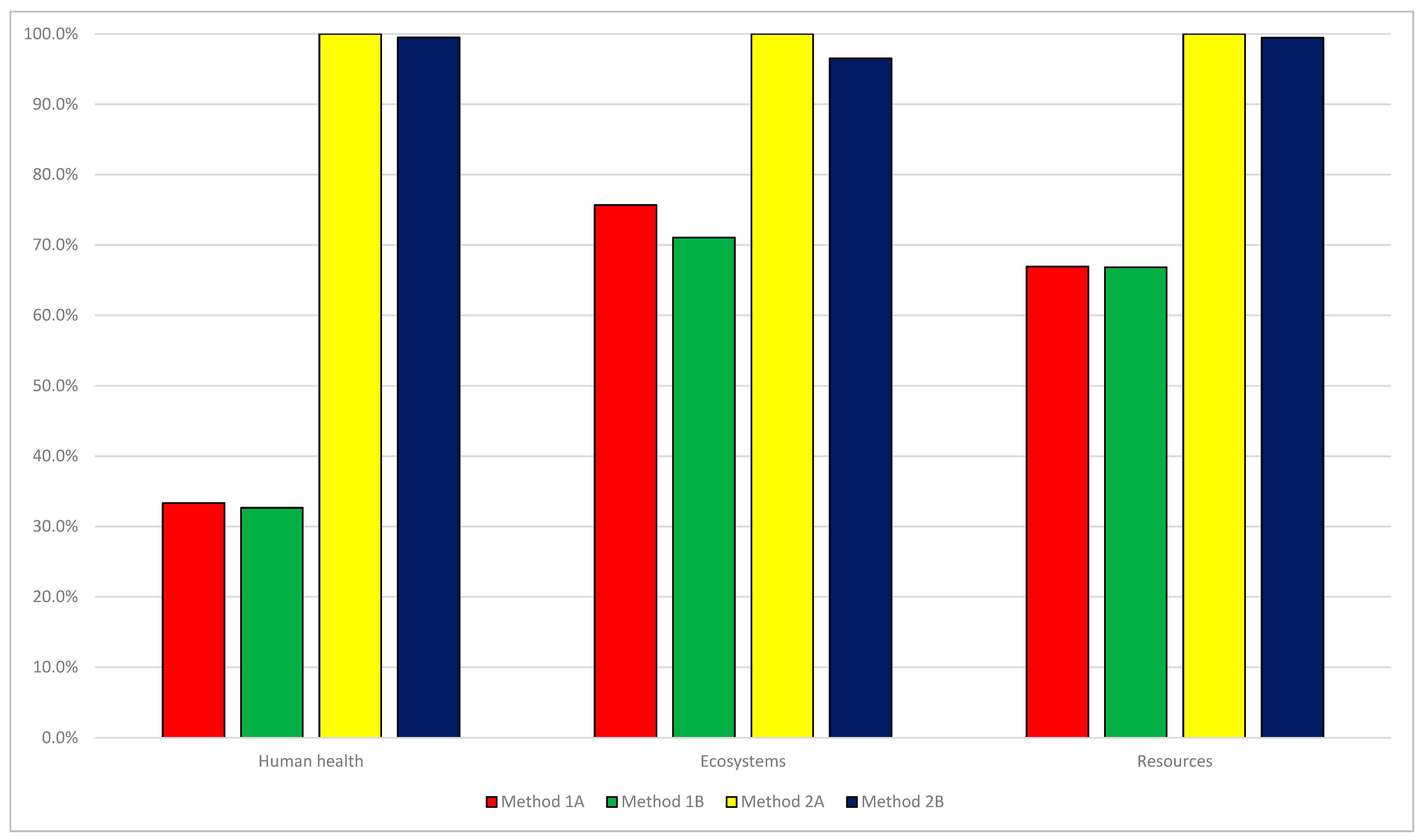
3.2.3. LCA Comparison
3.2.4. Limitations of the Life Cycle Impact Assessment and Interpretation
4. Conclusions and Recommendations
Author Contributions
Funding
Institutional Review Board Statement
Informed Consent Statement
Data Availability Statement
Acknowledgments
Conflicts of Interest
References
- Bautista, B.; Garciano, L.; Lopez, L. Comparative Analysis of Shear Strength Parallel to Fiber of Different Local Bamboo Species in the Philippines. Sustainability 2021, 13, 8164. [Google Scholar] [CrossRef]
- Salzer, C.; Wallbaum, H.; Lopez, L.F.; Kouyoumji, J.L. Sustainability of Social Housing in Asia: A Holistic Multi-Perspective Development Process for Bamboo-Based Construction in the Philippines. Sustainability 2016, 8, 151. [Google Scholar] [CrossRef] [Green Version]
- Gupta, J.; Vegelin, C. Sustainable development goals and inclusive development. Int. Environ. Agreem. Polit. Law Econ. 2016, 16, 433–448. [Google Scholar] [CrossRef] [Green Version]
- Kulatunga, U.; Amaratunga, D.; Haigh, R.; Rameezdeen, R. Attitudes and perceptions of construction workforce on construction waste in Sri Lanka. Manag. Environ. Qual. Int. J. 2006, 17, 57–72. [Google Scholar] [CrossRef]
- Bianco, I.; Tomos, B.A.D.; Vinai, R. Analysis of the environmental impacts of alkali-activated concrete produced with waste glass-derived silicate activator—A LCA study. J. Clean. Prod. 2021, 316, 128383. [Google Scholar] [CrossRef]
- Ongpeng, J.; Guades, E.; Promentilla, M. Cross-Organizational Learning Approach in the Sustainable Use of Fly Ash for Geopolymer in the Philippine Construction Industry. Sustainabilty 2021, 13, 2454. [Google Scholar] [CrossRef]
- Van Vliet, K.; Pellenq, R.; Buehler, M.J.; Grossman, J.C.; Jennings, H.; Ulm, F.-J.; Yip, S. Set in stone? A perspective on the concrete sustainability challenge. MRS Bull. 2012, 37, 395–402. [Google Scholar] [CrossRef] [Green Version]
- Samad, S.; Shah, A. Role of binary cement including Supplementary Cementitious Material (SCM), in production of environmentally sustainable concrete: A critical review. Int. J. Sustain. Built Environ. 2017, 6, 663–674. [Google Scholar] [CrossRef]
- Justnes, H. How to Make Concrete More Sustainable. J. Adv. Concr. Technol. 2015, 13, 147–154. [Google Scholar] [CrossRef] [Green Version]
- UN Environment Programme. Eco-Efficient Cements: Potential, Economically Viable Solutions for a Low-CO2 Cement Based Industry; UN Environment Programme: Nairobi, Kenya, 2016; p. 64. [Google Scholar]
- Scrivener, K.L. Options for the future of cement. Indian Concr. J. 2014, 88, 11–21. [Google Scholar]
- Ouellet-Plamondon, C.; Scherb, S.; Köberl, M.; Thienel, K.-C. Acceleration of cement blended with calcined clays. Constr. Build. Mater. 2020, 245, 118439. [Google Scholar] [CrossRef]
- Nawel, S.; Mounir, L.; Hedi, H. Effect of temperature on pozzolanic reaction of Tunisian clays calcined in laboratory. SN Appl. Sci. 2020, 2, 157. [Google Scholar] [CrossRef] [Green Version]
- Meissner, H. Pozzolans Used in Mass Concrete. In Proceedings of the Symposium on Use of Pozzolanic Materials in Mortars and Concretes, San Francisco, CA, USA, 10–14 October 1949; ASTM International: West Conshohocken, PA, USA, 1950; p. 16. [Google Scholar]
- Jaskulski, R.; Jóźwiak-Niedźwiedzka, D.; Yakymechko, Y. Calcined Clay as Supplementary Cementitious Material. Materials 2020, 13, 4734. [Google Scholar] [CrossRef]
- Pierkes, R.; Schulze, S.E.; Rickert, J. Optimization of Cements with Calcined Clays as Supplementary Cementitious Materials; RILEM Bookseries; Springer: Dordrecht, The Netherlands, 2015; pp. 59–66. [Google Scholar] [CrossRef]
- Brooks, J.; Johari, M.M. Effect of metakaolin on creep and shrinkage of concrete. Cem. Concr. Compos. 2001, 23, 495–502. [Google Scholar] [CrossRef]
- Khan, M.S.H.; Nguyen, Q.D.; Castel, A. Carbonation of Limestone Calcined Clay Cement Concrete; RILEM Bookseries; Springer: Dordrecht, The Netherlands, 2017; pp. 238–243. [Google Scholar]
- Bishnoi, S.; Maity, S.; Mallik, A.; Joseph, S.; Krishnan, S. Pilot scale manufacture of limestone calcined clay cement: The Indian experience. Indian Concr. J. 2014, 88, 22–28. [Google Scholar]
- Zhang, D.; Jaworska, B.; Zhu, H.; Dahlquist, K.; Li, V.C. Engineered Cementitious Composites (ECC) with limestone calcined clay cement (LC3). Cem. Concr. Compos. 2020, 114, 103766. [Google Scholar] [CrossRef]
- Argın, G.; Uzal, B. Enhancement of pozzolanic activity of calcined clays by limestone powder addition. Constr. Build. Mater. 2021, 284, 9–14. [Google Scholar] [CrossRef]
- Claisse, P.A. Water vapour and liquid permeability measurements in concrete. In Transport Properties of Concrete; Woodhead Publishing: Sawston, UK, 2021; pp. 103–114. [Google Scholar] [CrossRef]
- Raza, S.; Khan, M.K.I.; Menegon, S.J.; Tsang, H.-H.; Wilson, J.L. Strengthening and Repair of Reinforced Concrete Columns by Jacketing: State-of-the-Art Review. Sustainability 2019, 11, 3208. [Google Scholar] [CrossRef] [Green Version]
- Villar-Salinas, S.; Guzmán, A.; Carrillo, J. Performance evaluation of structures with reinforced concrete columns retrofitted with steel jacketing. J. Build. Eng. 2021, 33, 101510. [Google Scholar] [CrossRef]
- Del Zoppo, M.; Menna, C.; Di Ludovico, M.; Asprone, D.; Prota, A. Opportunities of light jacketing with Fibre Reinforced Cementitious Composites for seismic retrofitting of existing RC columns. Compos. Struct. 2021, 263, 113717. [Google Scholar] [CrossRef]
- Hu, X.; Chen, Z.; Bu, X. Axial compressive behavior on steel tube-retrofitted circular RC short columns with grout under preload. Structures 2021, 33, 2500–2519. [Google Scholar] [CrossRef]
- Shoraka, M.B.; Elwood, K.J.; Yang, T.Y.; Liel, A.B. Collapse Assessment of Non-Ductile, Retrofitted and Ductile Reinforced Concrete Frames. Spec. Publ. 2014, 297, 1–20. [Google Scholar]
- Menna, C.; Del Vecchio, C.; Di Ludovico, M.; Mauro, G.M.; Ascione, F.; Prota, A. Conceptual design of integrated seismic and energy retrofit interventions. J. Build. Eng. 2021, 38, 102190. [Google Scholar] [CrossRef]
- Salgado, R.A.; Apul, D.; Guner, S. Life cycle assessment of seismic retrofit alternatives for reinforced concrete frame buildings. J. Build. Eng. 2020, 28, 101064. [Google Scholar] [CrossRef]
- Júlio, E.S.; Branco, F.; Silva, V.D. Structural rehabilitation of columns with reinforced concrete jacketing. Prog. Struct. Eng. Mater. 2003, 5, 29–37. [Google Scholar] [CrossRef] [Green Version]
- Di Trapani, F.; Malavisi, M.; Marano, G.C.; Sberna, A.P.; Greco, R. Optimal seismic retrofitting of reinforced concrete buildings by steel-jacketing using a genetic algorithm-based framework. Eng. Struct. 2020, 219, 110864. [Google Scholar] [CrossRef]
- Liu, X.; Lu, Z.-D.; Li, L.-Z. The Use of Bolted Side Plates for Shear Strengthening of RC Beams: A Review. Sustainability 2018, 10, 4658. [Google Scholar] [CrossRef] [Green Version]
- Wu, Y.F.; Griffith, M.C.; Oehlers, D.J. Improving the Strength and Ductility of Rectangular Reinforced Concrete Columns through Composite Partial Interaction: Tests. J. Struct. Eng. 2003, 129, 1183–1190. [Google Scholar] [CrossRef]
- Palacios-Munoz, B.; Gracia-Villa, L.; Zabalza-Bribián, I.; López-Mesa, B. Simplified structural design and LCA of reinforced concrete beams strengthening techniques. Eng. Struct. 2018, 174, 418–432. [Google Scholar] [CrossRef] [Green Version]
- Maes, B.; Buyle, M.; Audenaert, A.; Craeye, B. Enhanced fly ash use in concrete: Ex-ante LCA on an emerging electro-mass separation technology. Clean. Eng. Technol. 2021, 2, 100076. [Google Scholar] [CrossRef]
- Habert, G.; Arribe, D.; Dehove, T.; Espinasse, L.; Le Roy, R. Reducing environmental impact by increasing the strength of concrete: Quantification of the improvement to concrete bridges. J. Clean. Prod. 2012, 35, 250–262. [Google Scholar] [CrossRef]
- Heede, P.V.D.; Maes, M.; Gruyaert, E.; De Belie, N. Full probabilistic service life prediction and life cycle assessment of concrete with fly ash and blast-furnace slag in a submerged marine environment: A parameter study. Int. J. Environ. Sustain. Dev. 2012, 11, 32. [Google Scholar] [CrossRef]
- Association of Structural Engineers of the Philippines (ASEP). National Structural Code of the Philippines; Association of Structural Engineers of the Philippines (ASEP): Quezon City, Philippines, 2015. [Google Scholar]
- International Organization for Standardization (ISO); Technical Committee ISO/TC 207. Life Cycle Assessment—Principles and Framework, ISO 14040:2006; International Organization for Standardization (ISO): Geneve, Switzerland, 2006. [Google Scholar]
- Huijbregts, M.A.; Steinmann, Z.J.; Elshout, P.M.; Stam, G.; Verones, F.; Vieira, M.; Zijp, M.; Hollander, A.; van Zelm, R. ReCiPe 2016: A Harmonized Life Cycle Impact Assessment Method at Midpoint and Endpoint Level: Report I: Characterization, RIVM Report 2016-0104; National Institute for Public Health and the Environment (RIVM): Bilthoven, The Netherlands, 2016; p. 194. Available online: https://www.rivm.nl/bibliotheek/rapporten/2016-0104.pdf (accessed on 18 December 2021).
- Goedkoop, M.; Huijbregts, M. ReCiPe 2008 Characterisation; Pré Sustainability: Amersfoort, The Netherlands, 2013; pp. 4–20. [Google Scholar]
- Mutel, G. Ecoinvent Database: Geographies. Ecoinvent. Available online: https://ecoinvent.org/the-ecoinvent-database/geographies/ (accessed on 4 December 2021).
- Pré Sustainability. Simapro Database Manual: Methods Library; Pré Sustainability: Amersfoort, The Netherlands, 2014; pp. 3–48. [Google Scholar]
- Tokar, E.J.; Benbrahim-Tallaa, L.; Waalkes, M.P. Metal ions in human cancer development. Metal Ions Life Sci. 2011, 8, 375–401. [Google Scholar]
- Kalbar, P.P.; Birkved, M.; Nygaard, S.E.; Hauschild, M. Weighting and Aggregation in Life Cycle Assessment: Do Present Aggregated Single Scores Provide Correct Decision Support? J. Ind. Ecol. 2016, 21, 1591–1600. [Google Scholar] [CrossRef] [Green Version]
- Wu, D.; Li, Q.; Ding, X.; Sun, J.; Li, D.; Fu, H.; Teich, M.; Ye, X.; Chen, J. Primary Particulate Matter Emitted from Heavy Fuel and Diesel Oil Combustion in a Typical Container Ship: Characteristics and Toxicity. Environ. Sci. Technol. 2018, 52, 12943–12951. [Google Scholar] [CrossRef] [PubMed]


| Mortar Used | Retrofitting Method | Compressive Strength (28 Days) | Composition | Design Mix (kg per m3) | Reference |
|---|---|---|---|---|---|
| OPC with Partial Replacement of Calcined Clay and Limestone Filler | Method 1B and Method 2B | 35.5 MPa | Cement | 400 | [21] |
| Fine Aggregates | 1375 | ||||
| Calcined Clay | 80 | ||||
| Limestone Filler | 20 | ||||
| Water (w/c = 0.53) | 265 | ||||
| Pure OPC Based | Method 1A and Method 2A | 35 MPa | Portland Cement | 544 | |
| Sand | 1342 | [22] | |||
| Water (w/c = 0.65) | 354 |
| Material | Route | Transport Distance (Raw Material to Plant) | Transport Distance (Plant to Site) | Transport Type | |
|---|---|---|---|---|---|
| From | To | ||||
| Natural Aggregate | Quarrying Site in Rizal | Concrete Batching Plant in Rizal | 15 km | 45 km | Truck (16–32 t) |
| Cement | Cement Factory in Rizal | 15 km | 45 km | ||
| Calcined Clay | Source in Batangas | 105 km | 45 km | ||
| Steel | Raw Material Source in Bulacan | Steel Mill in Rizal | 75 km | 70 km | |
| Retrofit Method | Cement | Calcined Clay | Limestone Filler | Fine Aggregates | Reinforcement Bars | Steel Plate | Water |
|---|---|---|---|---|---|---|---|
| Method 1A | 7880 | 22,928 | 4716 | 5380 | |||
| Method 1B | 6200 | 1217 | 306 | 20,907 | 4716 | 4033 | |
| Method 2A | 4840 | 11,726 | 8944 | 3095 | |||
| Method 2B | 3600 | 701 | 177 | 12,024 | 8944 | 2321 |
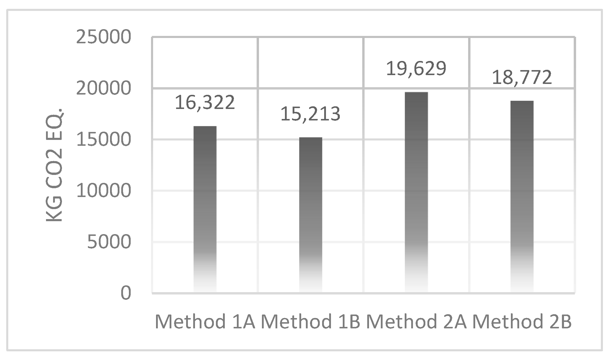
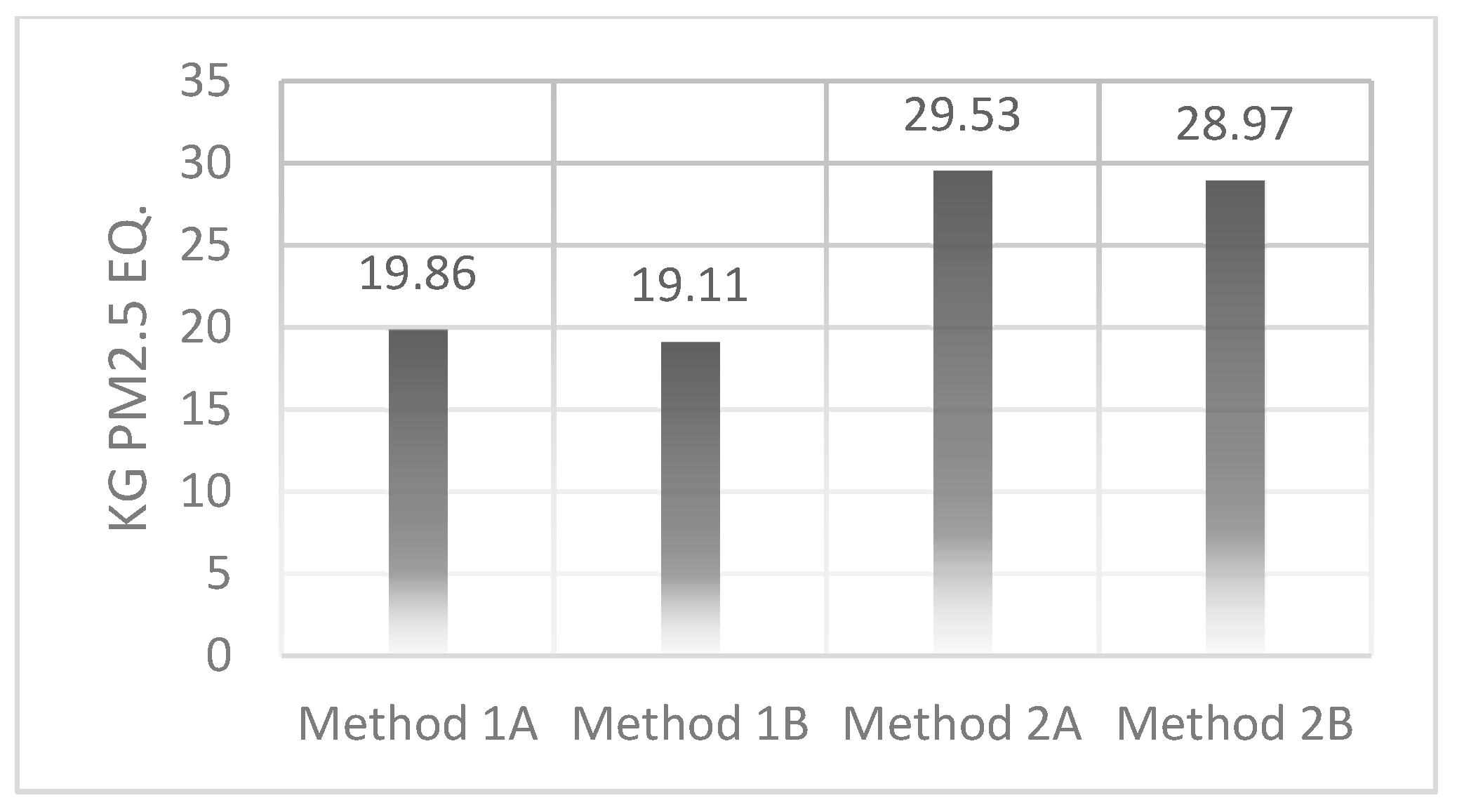
| Category | SimaPro Input | Input Values | Units | Human Carcinogenic Toxicity | Particulate Matter Formation | Global Warming Potential | |
|---|---|---|---|---|---|---|---|
| kg 1.4-DCB Emitted eq | kg PM2.5 eq | kg CO2 eq | |||||
| Materials | Portland Cement | Cement, Portland {RoW}|production|APOS, U | 6200 | kg | 89.08 | 3.37 | 5279.89 |
| Sand | Sand {RoW}| gravel and quarry operation|APOS, U | 20,907 | kg | 19.09 | 0.20 | 85.91 | |
| Reinforcing Steel | Reinforcing steel {RoW}|production|APOS, U | 4716 | kg | 15,041.03 | 15.13 | 9364.68 | |
| Tap Water | Tap water {GLO}|market group for|APOS, U | 4033 | kg | 1.73 | 0.01 | 3.20 | |
| Calcined Clay | Calcined clay {RoW}|market for calcined clay|APOS, U | 1217 | kg | 14.92 | 0.16 | 311.82 | |
| Limestone Filler | Limestone, crushed, washed {RoW}|market for limestone, crushed, washed|APOS, U | 306 | kg | 0.16 | 0.01 | 1.50 | |
| Processes | Concrete Production | Diesel, burned in building machine {GLO}|processing|APOS, U | 237.8 | MJ | 1.54 | 0.06 | 21.59 |
| Heat, district or industrial, natural gas {RoW}|market for heat, district or industrial, natural gas|APOS, U | 161.6 | MJ | 0.08 | 0.00 | 6.24 | ||
| Electricity, medium voltage {GLO}| market group for|APOS, U | 62.4 | kWh | 2.10 | 0.10 | 44.76 | ||
| Transportation | Transport, freight, lorry 16–32 metric ton, EURO6 {RoW}|transport, freight, lorry 16–32 metric ton, EURO6|APOS, U | 550.0 | tkm | 5.46 | 0.09 | 93.30 | |
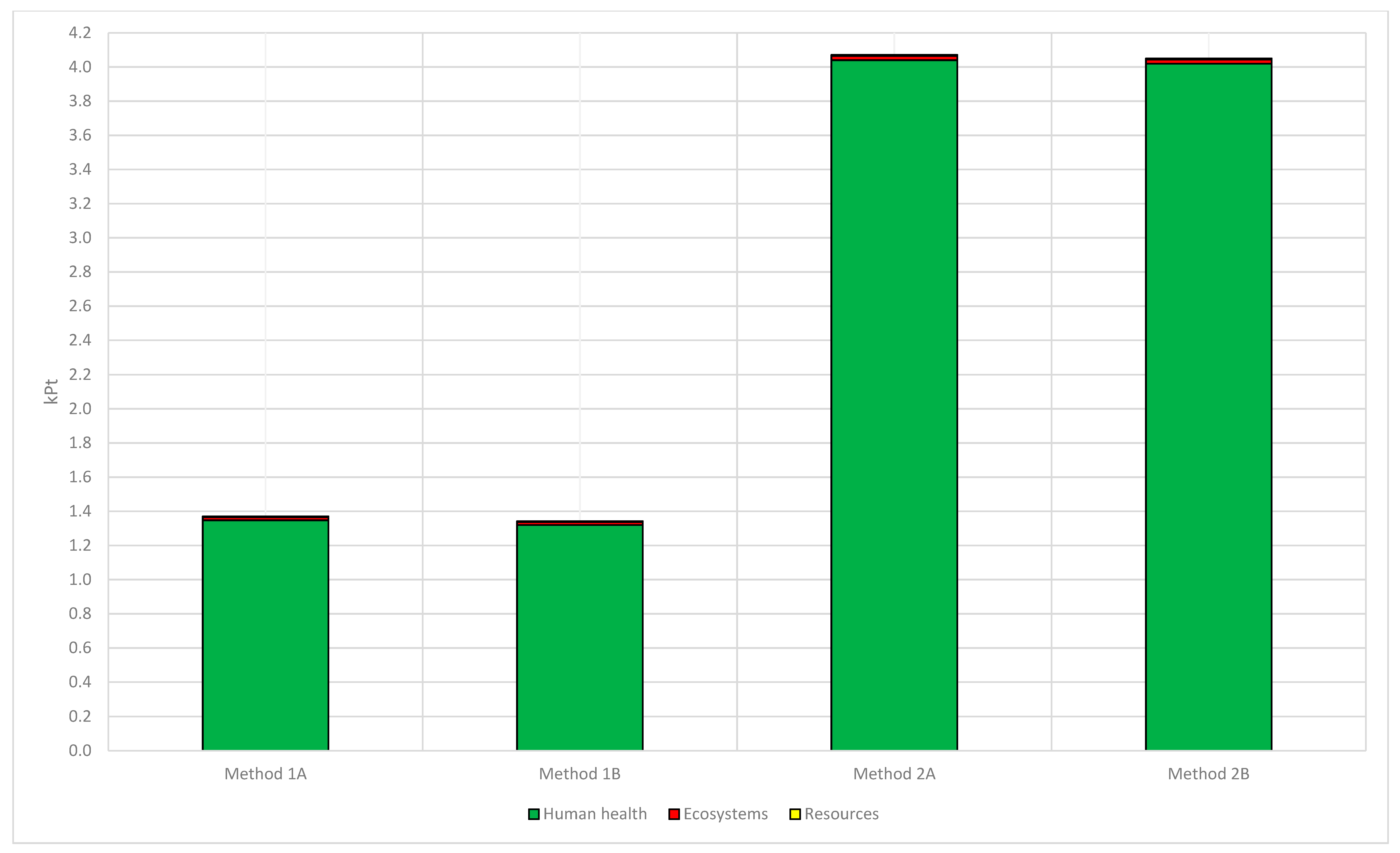
| Damage Category | Units | Method 1A | Method 1B | Method 2A | Method 2B |
|---|---|---|---|---|---|
| Human Health | DALY | 0.081 | 0.079 | 0.242 | 0.241 |
| Ecosystems | species. yr | 6.91 × 10⁻⁵ | 6.49 × 10⁻⁵ | 9.13 × 10⁻⁵ | 8.81 × 10⁻⁵ |
| Resources | USD2013 | 672 | 671 | 1003 | 998 |
Publisher’s Note: MDPI stays neutral with regard to jurisdictional claims in published maps and institutional affiliations. |
© 2022 by the authors. Licensee MDPI, Basel, Switzerland. This article is an open access article distributed under the terms and conditions of the Creative Commons Attribution (CC BY) license (https://creativecommons.org/licenses/by/4.0/).
Share and Cite
Bautista, B.E.; Ongpeng, J.M.C.; Razon, L.F. LCA of Mortar with Calcined Clay and Limestone Filler in RC Column Retrofit. Sustainability 2022, 14, 1175. https://doi.org/10.3390/su14031175
Bautista BE, Ongpeng JMC, Razon LF. LCA of Mortar with Calcined Clay and Limestone Filler in RC Column Retrofit. Sustainability. 2022; 14(3):1175. https://doi.org/10.3390/su14031175
Chicago/Turabian StyleBautista, Brian E., Jason Maximino C. Ongpeng, and Luis F. Razon. 2022. "LCA of Mortar with Calcined Clay and Limestone Filler in RC Column Retrofit" Sustainability 14, no. 3: 1175. https://doi.org/10.3390/su14031175
APA StyleBautista, B. E., Ongpeng, J. M. C., & Razon, L. F. (2022). LCA of Mortar with Calcined Clay and Limestone Filler in RC Column Retrofit. Sustainability, 14(3), 1175. https://doi.org/10.3390/su14031175