Article

Theoretical Analysis of Ultimate Main Span Length for Arch Bridge

1
Poly Changda Engineering Co., Ltd., Guangzhou 510620, China
2
State Key Laboratory of Disaster Reduction in Civil Engineering, Tongji University, Shanghai 200092, China
*
Author to whom correspondence should be addressed.
Sustainability 2022, 14(24), 17043; https://doi.org/10.3390/su142417043
Submission received: 29 October 2022 / Revised: 9 December 2022 / Accepted: 15 December 2022 / Published: 19 December 2022

Abstract

:
The advancement of construction techniques and high-performance sustainable materials enables the increase of span length for arch bridge. It is of great importance to study the theoretical ultimate span length of arch bridge. Based on the parabolic and catenary arch axes, the analytical solutions of ultimate span length of arch bridge are solved using theoretical derivation accounting for the strength, in-plane stability and out-plane stability conditions, respectively. Then, the use of high-performance concrete, reactive powder concrete and high-strength steel is considered to study the relationship between theoretical ultimate span length and rise-span ratio as well as material strength for concrete and steel arch bridges. The results show that the theoretical ultimate span length derived by catenary arch axis is smaller by about 2–6% than that obtained by parabolic arch axis, but the difference is insignificant. When the rise-span ratio is 1/5, the theoretical ultimate span length for concrete arch bridge using R200 reactive powder concrete can reach 2000 m (2161 m for catenary arch axis and 2099 m for parabolic arch axis) while the main span of steel arch bridge using Q690 high-strength steel can be longer than 2500 m (2948 m for catenary arch axis and 2865 m for parabolic arch axis).

1. Introduction

Long-span arch bridge is one of competitive types of bridge to cross rivers and canyons due to its favorable durability and mechanical performance [1]. Recent years, many long-span arch bridges were constructed in China and rewritten the world record of the main span. For steel arch bridges, Chaotianmen Bridge with a main span of 552 m set a world record in 2009 [2]. For concrete arch bridge, the construction of the Tianelongtan Bridge in Guangxi Province, China will break the record of the span length of arch bridge to the value of 600 m [3]. Table 1 summarizes 15 world records of the main span length during the development of arch bridge, including the year of the completion, years of the record, material of the bridge etc. Compared with the rapid development of suspension bridge and cable-stayed bridge, the main span length of arch bridge is almost at a standstill for a long time. It can be noted that since the completion of the first 500 m-main-span-level arch bridge (Bayonne Bridge with the main span of 504 m in the USA) in 1931 [4], the span length has only been increased to 575 m in past about 90 years after the completion of Pingnan 3rd Bridge in 2020 [5]. However, the span capacity of arch bridge is not well examined, especially with the rapid development of advanced construction techniques and new materials. The span length of arch bridge could be continuously broken in the future. The study of ultimate main span length of arch bridge has become a hotspot in the bridge engineering community [6,7,8,9,10].
Some pioneering studies on the ultimate span of arch bridge have been performed in past several decades, as summarized in Table 2. As can be seen, the steel, concrete or CFST are customarily employed for the arch. The catenary and parabolic arch rib axes are usually treated as the reasonable arch axes under dead load with the rise-to-span ratios of 1/3~1/5. The ultimate span length is almost positively relevant to the material strength and steel arch bridge is considered to have a larger span capacity than that of concrete. The ultimate span length for concrete arch bridge is about 600 m when the C100 or lower grade of concrete is utilized. Comparatively, except Tang [8] and Järvenpää and Jutila [13], the steel arch bridge is able to reach 1000 m when the Q460 or lower grade if steel is employed. As for the CFST arch bridge, Wang [14] proposed an optimization method for solving the ultimate span length based on the response surface method, founding that the maximum span length of the CFST arch bridge can reach up to 821 m if the Q420 steel and C80 concrete were utilized.
With the advancement of concrete-filled steel tube and stiff skeleton concrete arch bridge technology as well as the development of new materials, such as high-performance steel and ultra-high-performance concrete, the main span length of arch bridge is expected to make a breakthrough. Among them, the concrete arch bridge has natural rationality in the application of materials. With the application of ultra-high-performance concrete, the spanning capacity of concrete arch bridge increases constantly. And the stiff skeleton construction method provides a reasonable solution for the construction of long-span concrete arch bridge. It can be said that the concrete arch bridge has a very potential to continuously break the span record. As for the steel arch bridge, although it has no economic advantage, it is proved to have a strong spanning capacity according to the theoretical analysis. Chen and Liu [20] believes that it is feasible to build a 3300 m main span steel arch bridge. Some trial design schemes of super-span arch bridges have also been proposed to validate the feasibility. Čandrlić and Radić [21] studied the applicability of reactive powder concrete (RPC) to the construction of 1000 m main span concrete arch bridge. Zheng et al. [22] performed a feasibility study on the construction of 700 m main span concrete filled steel tube arch bridge. Shao et al. [23,24] proposed a new system of super long-span steel UHPC composite truss arch bridge and proved its feasibility to construct the 800 m and 1000 m main span arch bridges.
Although there are some theoretical and numerical studies on investigating the ultimate span length of long-span arch bridges, some other conditions, such as the out-of-plane stability and the application of recent high-performance sustainable materials are not well considered. To further investigate the theoretical ultimate span length of arch bridge, this study performs the theoretical analysis of ultimate span length of arch bridges using parabolic and catenary arch axes, respectively considering the strength, in-plane stability and out of plane stability conditions. The relationships between the theoretical ultimate span length and the rise-span ratio as well as the material strength are comparatively studied. The ultimate span lengths for concrete and steel arch bridges are finally obtained with respect to different material grades and rise-span ratios.

2. Parabolic Arch Axis

2.1. Strength Condition

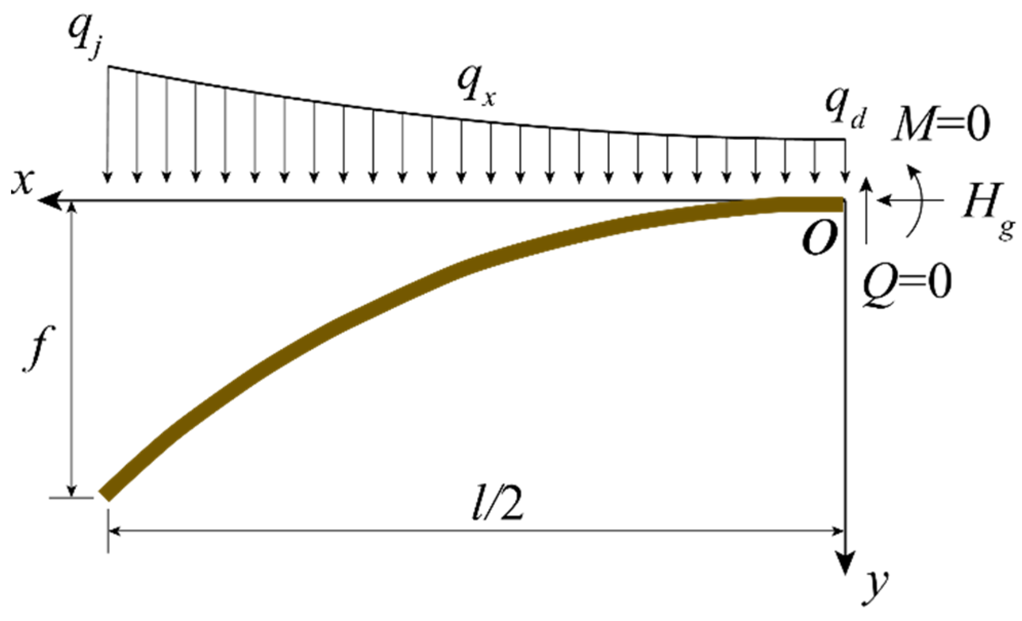
As shown in Figure 1, a half-span arch is subjected to the uniformly distributed load with the density of q (N/m). l (m) and f (m) are the span length and rise of the arch, respectively. M (N·m), Hg (N) and Q (N) are moment, axial force, and shear force at the apex of arch, respectively. By setting the origin of the coordinate at the apex of arch, the parabolic curve of the arch axis is formulated as:
y = 4 f x 2 / l 2
When the dead load is assumed to be the uniformly distributed load as shown in Figure 1, the dead load compression line coincides with the parabolic arch axis. That is, there is only axial compression force in the arch under the action of dead load, and there is no bending moment and shear force. At the apex of arch, the horizontal compression force under dead load can be solved as:
H g = M j f = 0 l / 2 q ( l / 2 x ) d x f = q l 2 8 f = q l 8 n
where M j is the bending moment at the abutment of the arch due to the half-span dead load, n = f/l is the ratio of rise to span. The axial force at the abutment of the arch can be easily obtained:
N j = H g cos θ j = H g 1 / 1 + tan θ j 2 = q l 8 n 1 + 16 n 2
where θj (°) is the angle between the tangent direction of the arch axis at the abutment and horizontal direction. Assume that the proportion of the self-weight of the arch to the total load is λ. The arch is assumed to have a uniform cross section with the area of A (m2) and apparent density of γ (N/m3). The density of the dead load is therefore estimated by q = γA. The design value of material compressive strength of the arch is fd (MPa). Based on the General Code for Design of Highway Bridges and Culverts (JTG D60-2015) [25], the structural importance factor of 1.1 and partial safety factor of permanent action of 1.2 are considered. The strength condition of theoretical ultimate span length for arch bridge based on parabolic arch axis is then derived as:
1.1 × 1.2 × N j A = 1.32 × γ l 8 n 1 + 16 n 2 λ f d
or
l l max 1 = 8 λ n f d 1.32 γ 1 + 16 n 2 = 6.06 λ n 1 + 16 n 2 f d γ
It can be seen that the value of n / 1 + 16 n 2 increases with n, suggesting that the ultimate span length increases with the rise-span ratio in strength condition.

2.2. Stability Conditions

2.2.1. In-Plane Stability

Although the parabolic arch only bears axial compressive force without bending moment under the action of uniform load, the axial compressive force varies along the arch axis. Meanwhile, the variation of the curvature of the arch results in that the coefficients of the equilibrium differential equation are not constant. The theoretical solution of the equation is usually unavailable. In engineering applications, the effective calculation length S0 of the arch is often used to approximately describe the critical compressive force. Similar to the centrally compressed member, the critical compressive force of the in-plane stability (normally used as the critical compressive force at the cross section of the 1/4 span) can be calculated by [26]:
N cr 1 = π 2 E I z l z 2 = π 2 E I z ( 0.36 l a ) 2
where lz (m) is the calculation length of in-plane stability of the arch, lz = 0.36la for unhinged arch, in which la is the arc length of the arch axis, E (MPa) is the modulus of elasticity of the material used by the arch, Iz (m4) is the moment of inertia of the cross section with respect to the vertical direction. The arc length of the arch axis can be approximately calculated using the first two terms of the Taylor’s series expansion:
l a = 2 0 l / 2 1 + ( 8 n l x ) 2 d x 2 0 l / 2 [ 1 + 1 2 ( 8 n l x ) 2 ] d x = l ( 1 + 8 3 n 2 )
Under the action of uniform load, the axial compressive force at the cross-section of 1/4 span is expressed as:
N l / 4 = H g cos θ l / 4 = H g 1 / 1 + tan θ l / 4 2 = q l 8 n 1 + 4 n 2
where θ l / 4 (°) is the angle between the tangent direction of the arch axis at 1/4 span and horizontal direction. By setting a stability safety coefficient of φ = 4.0, the in-plane stability condition of theoretical ultimate span length for arch bridge based on parabolic arch axis is then derived as:
l 3 2 λ π 2 0.36 2 × n 1 + 4 n 2 ( 1 + 8 n 2 / 3 ) 2 × E γ × I z A
where λ is the ratio of slenderness. To calculate the Iz/A in Equation (9), a box cross section with the width of b (m), height of h (m) and thickness of plate of t (m) is introduced. The high-order terms with respect to t can be ignored when calculating the moment of inertia since the value of t is relatively much smaller than b and h. The ratio of the moment of inertia and area of the section can be calculated by:
I z A = 3 b h 2 + h 3 12 ( b + h )
I y A = 3 h b 2 + b 3 12 ( b + h )
where Iy (m4) is the moment of inertia with respect to the lateral direction. The ratio between the height of the arch cross section and span length h/l is usually at the range of 1/50~1/100. The width of the section to the span length ratio b/l is at the range of 1/20~1/30. If h/l = 1/50 and b/l = 1/30, the in-plane stability condition can be rewritten as:
l l max 2 = 0.0114 λ n 1 + 4 n 2 ( 1 + 8 n 2 / 3 ) 2 E γ
As can be seen, the value of n / [ 1 + 4 n 2 ( 1 + 8 n 2 / 3 ) 2 ] increases first before decreasing with n at the range of 0 < n < 1 and has the maximum of 0.17 at n = 0.29.

2.2.2. Out-of-Plane Stability

Similar to the element subjected to the axially loaded compression, the critical compressive force related to the out-of-plane stability of the arch can be expressed as:
N cr 2 = π 2 E I y l y 2 = π 2 E I y ( ζ l 2 ( 1 4 n + n ) ) 2
where ly (m) is the calculation length of out-of-plane stability of the arch, l y = ζ l 2 ( 1 4 n + n ) for unhinged arch, in which ζ is the calculation length coefficient of out-of-plane stability, as listed in Table 3.
Based on the in-plane stability condition of N l / 4 λ N cr 2 / φ and the safety factor of φ = 4.0, the out-of-plane stability condition of theoretical ultimate span length for arch bridge based on parabolic arch axis is then derived as:
l l max 3 = 0.2050 λ n 3 ζ 2 ( 1 + 4 n 2 ) 5 2 E γ
where the value of ζ increase with n, but n 3 / ( 1 + 4 n 2 ) 5 2 increase first before decreasing with n at the range of 0 < n < 1 and has the maximum at n = 0.61.

3. Catenary Arch Axis

3.1. Strength Condition

When the dead load density (gravity per unit length) over the arch is continuously distributed and gradually increases from the apex to the abutment of the arch and has an approximate linear relationship with the arch axis, its reasonable arch axis is a catenary. The shape of the catenary is not only related to the rise-span ratio, but also depends on the arch axis coefficient. The force of the catenary arch can be optimized by adjusting the arch axis coefficient so that has a relatively strong adaptability to non-uniform loads. The catenary is the most commonly used arch axis for log-span arch bridges. As shown in Figure 2, a half-span arch with the span length of l (m) and rise of f (m) is subjected to the non-uniform load. The density of the load at the abutment and apex of the arch are qj (N/m) and qd (N/m), respectively. M (N·m), Hg (N) and Q (N) are moment, axial force and shear force at the apex of arch, respectively. By setting the origin of the coordinate at the apex of arch, the load density at the location of x is expressed as:
q x = q d ( 1 + m 1 f y )
where m = qj/qd is the arch axis coefficient. The catenary arch axis is formulated as:
y = f m 1 ( cosh k ξ 1 )
where ξ = 2 x / l , k = ln ( m + m 2 1 ) . When the dead load is continuously distributed and gradually increased from the apex to the abutment of the arch and has an approximately linear relationship with the arch axis, the dead load compression line coincides with the catenary arch axis. That is, there is only axial compression force in the arch under the action of dead load, and there is no bending moment and shear force. At the apex of arch, the horizontal compression force under dead load can be solved as:
H g = M j f = 0 l / 2 q x ( l / 2 x ) d x f = q d l 4 n k 2 ( m 1 )
The compressive force at the abutment of the arch is:
N j = H g cos θ j = H g 1 / 1 + tan θ j 2 = q d l 4 n k 2 ( m 1 ) 1 + 4 n 2 k 2 m + 1 m 1
Similar to the parabolic arch axis in Section 2.1, assume that the proportion of the self-weight of the arch to the total load is λ. The arch is assumed to have a uniform cross section with the area of A (m2) and apparent density of γ. The strength condition of theoretical ultimate span length for arch bridge based on catenary arch axis is derived as:
l l max 1 4 λ n k 2 f d 1.32 γ ( m 1 ) 1 + 4 n 2 k 2 m + 1 m 1 = 3.03 λ n k 2 ( m 1 ) 1 + 4 n 2 k 2 m + 1 m 1 f d γ

3.2. Stability Conditions

3.2.1. In-Plane Stability

Similar to the centrally compressed member, the critical compressive force of the in-plane stability of catenary arch (normally used as the critical compressive force at the cross section of the 1/4 span) can be calculated by using Equation (6). The arc length of the catenary arch axis can be approximately calculated by:
l a = 2 0 l / 2 1 + ( 2 n k ( m 1 ) sinh k ξ ) 2 d x = 2 0 l / 2 1 + 4 n 2 k 2 ( m 1 ) 2 ( sinh k 2 x l ) 2 d x
where the integral equation is like 1 + a sinh 2 ( b x ) d x , which is the second type of the elliptic integral if a ≠ 1. When a = 1, or 4 n 2 k 2 = ( m 1 ) 2 :
cos θ j = 1 1 + tan θ j 2 = 1 1 + sinh k = 1 m
That means m = 1 / cos θ j when 4 n 2 k 2 = ( m 1 ) 2 . The load density at the abutment of the arch is expressed as:
q j = m q d = γ A cos θ j
By introducing an element of the abutment of the arch with the arch length of ds, Equation (22) can be rewritten as:
q j d x = γ A d x cos θ j = γ A d s
where d x = d s cos θ j is the horizontal projection length of the element. Equation (23) suggests that the dead load density at the abutment of the arch is exactly equal to the self-weight of the arch with a uniform cross-section at abutment. Then, the arch axis is just the reasonable arch axis under the action of self-weight of the arch. That is, the reasonable arch axis coefficient can be determined by the equation of 2 n k = m 1 . By substituting k = ln ( m + m 2 1 ) into this equation produces:
m 1 ln ( m + m 2 1 ) = 2 n
Equation (24) can be used to determine a reasonable arch axis coefficient m based on the rise-span ratio n. The arc length of the catenary arch axis is therefore calculated by:
l a = 2 0 l / 2 1 + ( sinh k 2 x l ) 2 d x = l k sinh k
The axial compressive force at the cross-section of 1/4 span is expressed as:
N l / 4 = H g cos θ l / 4 = H g 1 / 1 + tan θ l / 4 2 = q d l 2 k cosh k 2
Based on the in-plane stability condition of N l / 4 λ N cr 2 / φ and the safety factor of φ = 4.0 as well as the cross-section property in Equation (10), the in-plane stability condition of theoretical ultimate span length for arch bridge based on catenary arch axis is then derived as:
l l max 2 = 0.0029 λ k 3 sinh 2 k cosh k 2 E γ

3.2.2. Out-of-Plane Stability

Similar to Equation (13), the critical compressive force related to the out-of-plane stability of the catenary arch can be expressed as:
q d l 2 k cosh k 2 λ 4.0 × π 2 E I y ζ 2 l 2 4 ( 1 4 n + n ) 2
or
l l max 3 = 0.0512 λ k n 2 ζ 2 cosh k 2 ( 1 + 4 n 2 ) 2 E γ

4. Theoretical Ultimate Span Length

Based on above theoretical derivation, the strength, in-plane stability and out-of-plane stability conditions of the parabolic and catenary arch axes are summarized listed in Table 4, respectively. The theoretical ultimate span length of arch bridges lmax (m) is expressed as
l max = min { l max 1 , l max 2 , l max 3 }
To further discuss the ultimate span length, the concrete and steel arch bridges with different materials are introduced and compared.

4.1. Concrete Arch Bridge

As suggested by the Specifications for Design of Highway Reinforced Concrete and Prestressed Concrete Bridges and Culverts (JTG 3362-2018) [27] and Technical Specification for Reactive Powder Concrete Structures (DBJ43/T 325-2017) [28], the design values of compressive strength fd and modulus of elasticity E for concrete are listed in Table 5. The apparent density of concrete γ = 26.0 kN/m3.
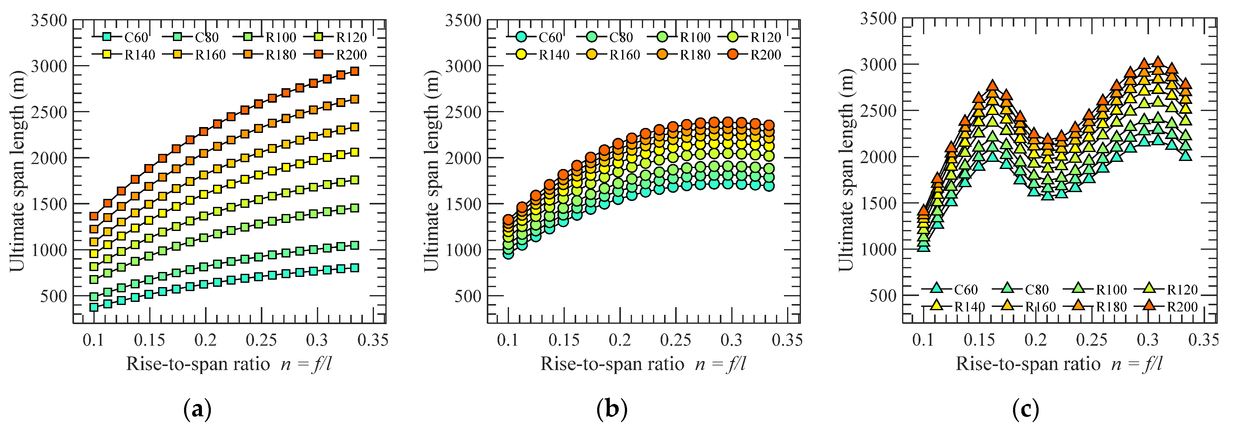
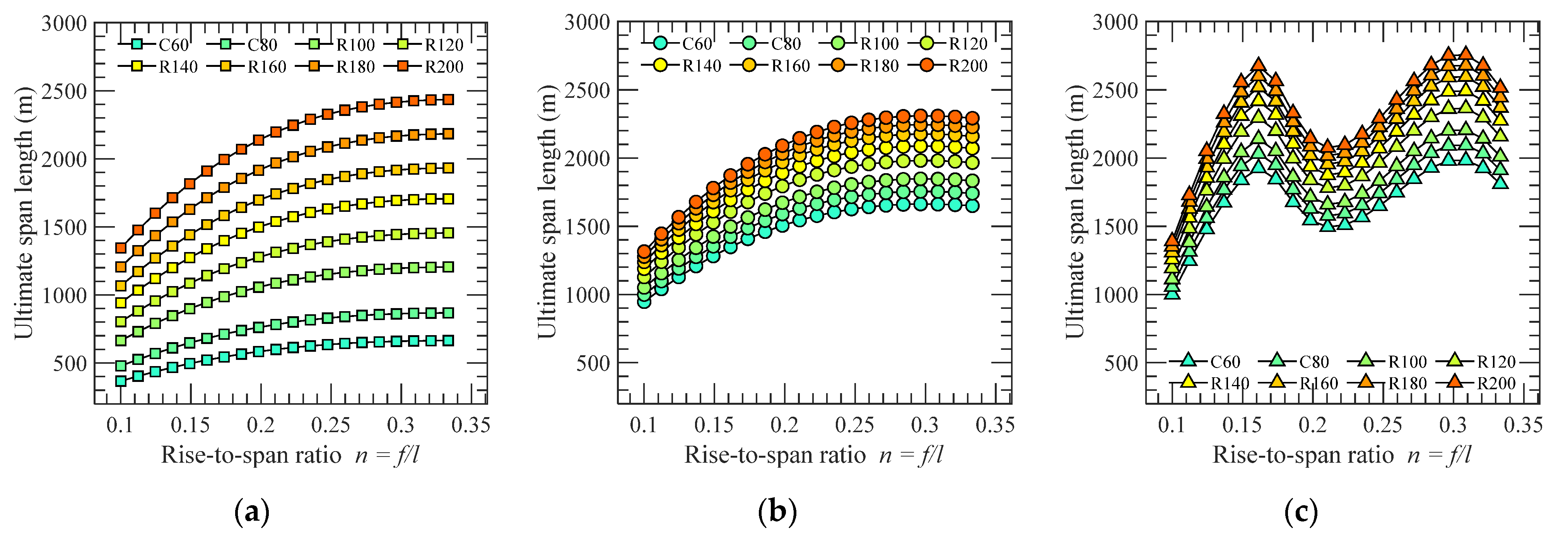
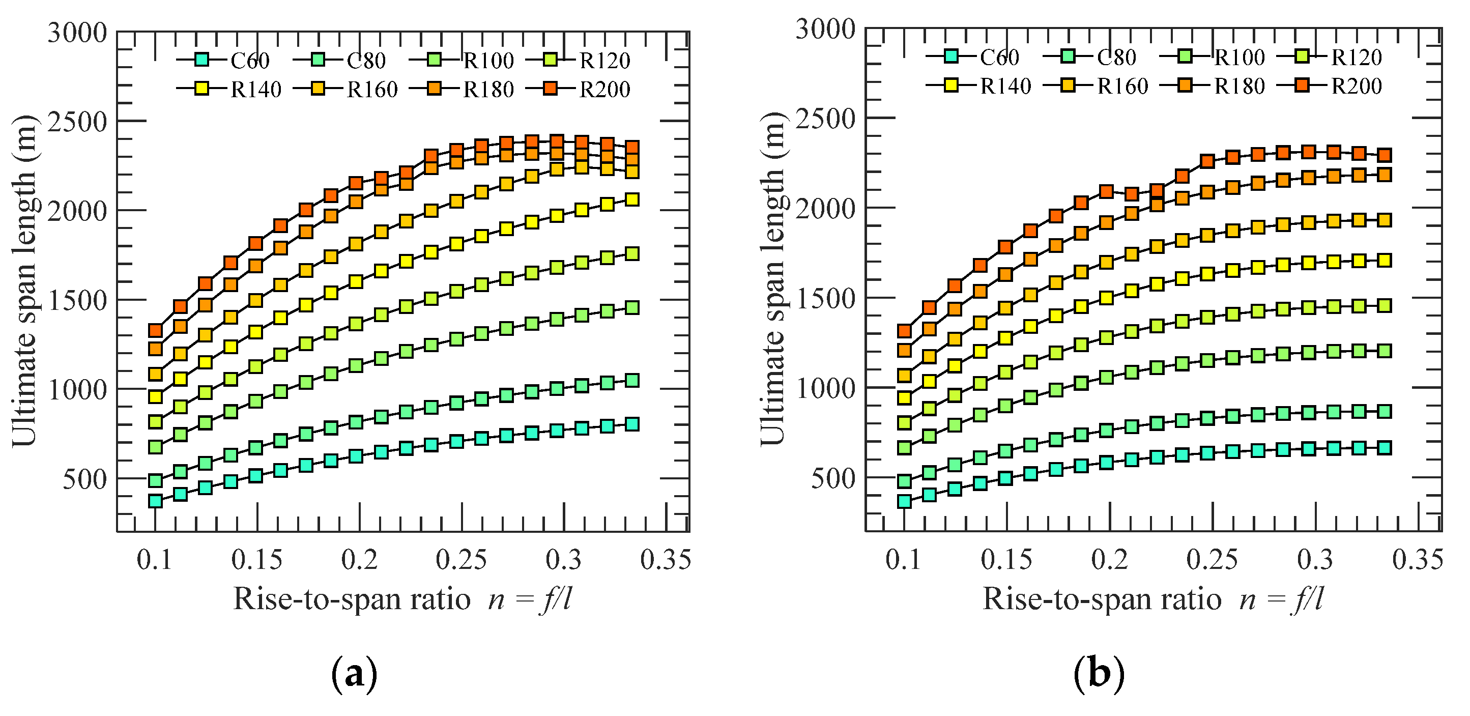
By substituting the design values of different grades of concrete in Table 5 into the theoretical solutions in Table 4, the ultimate span lengths of parabolic and catenary arch bridges with respect to the strength, in-plane stability and out-of-plane stability conditions can be readily obtained, as shown in Figure 3 and Figure 4. The final theoretical ultimate span length is shown in Figure 5.
As can be seen, the ultimate span length of arch bridge is mainly controlled by the strength condition as the increase of the grade of concrete. The stability condition starts to affect the result when the strength of the concrete reaches up to the grade of R160 for parabolic arch and R180 for catenary arch. The stability condition completely dominates the ultimate span length when the grade of R200 concrete is employed. Specifically, when the rise-span ratio is 1/5, the ultimate span lengths for parabolic and catenary arch axes are about 627 m and 586 m, respectively if the C60 concrete is used. This value can be increased to be 2160 m and 2099 m, respectively if the ultra-high-performance concrete with the grade of R200 is utilized.

4.2. Steel Arch Bridge

The high-performance steel has been well examined and applied in some real bridge structures. For example, the Q500q grade steel was utilized by Husutong Yangtze River Bridge completed in July 2020, which is the second longest span cable-stayed bridge. The Q690q grade steel was applied to the Jianghan 7th Arch Bridge with the main span of 408 m. As suggested by the Specifications for Design of Highway Steel Bridge (JTG D64-2015) [29] and the Structural Steel for Bridge (GB/T 714-2015) [30], the design strength fd of steel is listed in Table 5. The modulus of elasticity E = 2.06 × 10⁵ MPa. The apparent density of concrete γ = 78.5 kN/m3.
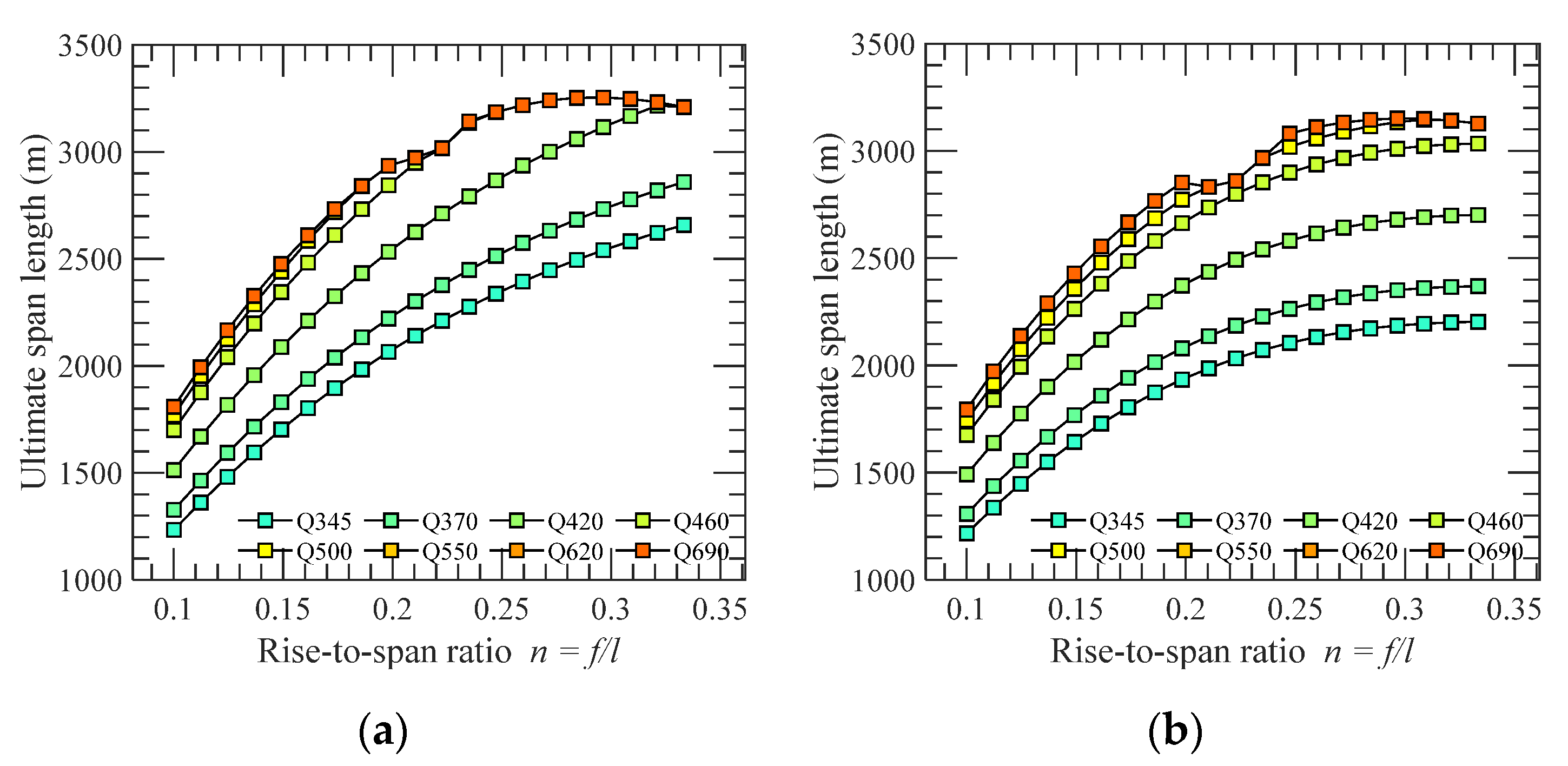
By substituting the design strength of different steel grades in Table 6 into the theoretical solutions in Table 4, the ultimate span lengths of parabolic and catenary arch bridges with respect to the strength, in-plane stability and out-of-plane stability conditions can be readily obtained, as shown in Figure 6 and Figure 7. The final theoretical ultimate span length is shown in Figure 8.
Similar to the concrete arch bridge, the ultimate span length of steel arch bridge is also mainly controlled by the strength condition as the increase of the grade of steel. The stability condition starts to affect the result when the strength of the steel reaches up to the grade of Q420 for parabolic arch and Q460 for catenary arch. The stability condition completely dominates the ultimate span length when the grade of Q500 steel is employed. Specifically, when the rise-span ratio is 1/5, the ultimate span lengths for parabolic and catenary arch axes are about 2077 m and 1942 m, respectively if the Q345 steel is used. This value can be increased to be 2948 m and 2865 m, respectively if the high-performance steel with the grade of Q690 is utilized.
For comparison purpose, Table 7 and Table 8 list the theoretical solutions of ultimate span length for concrete and steel arch bridges using parabolic and catenary arch axes, respectively when the rise-span ratio is 1/5. As can be seen, the results based on catenary arch axis are slightly smaller by about 2–6% than that of parabolic arch axis. This is because that the uniformly distributed load is assumed by the parabolic arch axis, which neglects the increment of dead load at abutment compared to the load at the apex of the arch.

5. Conclusions and Discussion

Based on the theoretical derivation of strength, in-plane stability and out-of-plane stability conditions, the theoretical solutions of ultimate span length for arch bridge using the parabolic and catenary arch axes are achieved, respectively. They are applied to estimate the ultimate span lengths of concrete and steel arch bridges with various rise-span ratios using different grades of material. The results show that the theoretical ultimate span length based on catenary arch axis is slightly smaller than that of parabolic arch axis. When the rise-span ratio of the bridge is 1/5, the theoretical ultimate span of concrete arch bridge can be longer than 2000 m if the ultra-high-performance concrete with the grade of R200 is utilized. As for steel arch bridge, the ultimate span length can be longer than 2500 m if the high-performance steel with the grade of Q690 is utilized.
The findings of ultimate span length in this study provide the basis to better understanding the length capacity of arch bridge when advanced new materials are utilized. It is worth mentioning that only the arch structure under the action of dead load is analyzed in this study. The design of a real long-span arch bridge is much more complicated. The effects of some other extreme loadings, such as wind [31,32,33], earthquake [34,35,36,37] and vehicle etc. could dominate the design of the arch. Moreover, such other issues, including instability of spandrel column for concrete deck arch bridges [38], strength of hangers for through arch bridge, local buckling instability etc. should be considered during the design of a real arch bridge. The difficulty of construction and rapid increase of cost are also great challenges for the completion of these very long-span arch bridges.

Author Contributions

All four co-authors contributed to the completion of this article. Conceptualization, Z.D. and Y.G.; methodology, Z.D. and G.F.; software, X.Z. and Z.D.; validation, G.F. and Y.G.; formal analysis, X.Z. and Z.D.; investigation, Z.D.; resources, Y.G.; data curation, Z.D.; writing—original draft preparation, G.F.; writing—review and editing, X.Z. and G.F.; visualization, Z.D.; supervision, Y.G.; project administration, G.F. and Y.G.; funding acquisition, G.F. and Y.G. All authors have read and agreed to the published version of the manuscript.

Funding

This research was funded by the National Natural Science Foundation of China (52108469, 51978527), the Shanghai Pujiang Program (20PJ1413600) and the Fundamental Research Funds for the Central Universities (22120220577).

Institutional Review Board Statement

Not applicable.

Informed Consent Statement

Not applicable.

Data Availability Statement

Any interested parties can contact the corresponding author directly via email for information on the data.

Conflicts of Interest

The authors declare no conflict of interest.

References

  1. Hu, N.; Dai, G.L.; Yan, B.; Liu, K. Recent development of design and construction of medium and long span high-speed railway bridges in China. Eng. Struct. 2014, 74, 233–241. [Google Scholar] [CrossRef]
  2. Cheng, J. Optimum design of steel truss arch bridges using a hybrid genetic algorithm. J. Constr. Steel Res. 2010, 66, 1011–1017. [Google Scholar] [CrossRef]
  3. Liu, J.P.; Chen, B.C.; Li, C.; Zhang, M.J.; Mou, T.M.; Tabatabai, H. Recent application of and research on concrete arch bridges in China. Struct. Eng. Int. 2022. [Google Scholar] [CrossRef]
  4. Thrall, A.P.; Billington, D.P. Bayonne Bridge: The Work of Othmar Ammann Master Builder. J. Bridge Eng. 2008, 13, 635–643. [Google Scholar] [CrossRef]
  5. Zheng, J.L.; Du, H.L.; Mu, T.M.; Liu, J.; Qin, D.; Mei, G.; Tu, B. Innovations in design, construction, and management of Pingnan Third Bridge—The largest-span arch bridge in the world. Struct. Eng. Int. 2022, 32, 134–141. [Google Scholar] [CrossRef]
  6. Nazmy, A.S. Stability and lode-carrying capacity of three-dimensional long-span steel arch bridges. Comput. Struct. 1997, 65, 857–868. [Google Scholar] [CrossRef]
  7. Salonga, J.; Gauvreau, P. Comparative study of the proportions, form, and efficiency of concrete arch bridges. J. Bridge Eng. 2014, 19, 04013010. [Google Scholar] [CrossRef]
  8. Tang, M.C. Super-long span bridges. Struct. Infrastruct. Eng. 2017, 13, 722–730. [Google Scholar] [CrossRef]
  9. Ge, Y.J. Challenge and development of long-span arch bridges in statics, dynamics and aerodynamics. In Proceedings of the ARCH 2019: 9th International Conference on Arch Bridges, Porto, Portugal, 2–4 October 2019. [Google Scholar]
  10. Zheng, J.L.; Wang, J.J. Concrete-Filled Steel Tube Arch Bridges in China. Engineering 2018, 4, 143–155. [Google Scholar] [CrossRef]
  11. Azzara, R.M.; Falco, A.D.; Girardi, M.; Pellegrini, D. Ambient vibration recording on the Maddalena Bridge in Borgo a Mozzano (Italy): Data analysis. Ann. Geophys. 2017, 60, S0441. [Google Scholar] [CrossRef] [Green Version]
  12. Lin, Y.P.; Zhang, Z.H.; Ma, B.; Zhou, L. Lupu arch bridge, Shanghai. Struct. Eng. Int. 2004, 14, 24–26. [Google Scholar] [CrossRef]
  13. Järvenpää, E.; Jutila, A. Ultimate spans and optimal rise relations of steel arches. In Proceedings of the IABSE Congress, New York, NY, USA, 4–6 September 2019. [Google Scholar]
  14. Wang, X.C. Study on the reasonable arch axis of long-span concrete-filled steel tubular arch bridge. Master’s Thesis, Chongqing Jiaotong University, Chongqing, China, 2019. [Google Scholar]
  15. Xia, M.; Liu, H. Disquisition of limitation span of arch bridge. Transp. Sci. Technol. 2005, 12, 39–42. [Google Scholar]
  16. Xia, M. Analysis of ultimate carrying capacity for long-span fixed arch bridge with thrust. Ph.D. Thesis, Tongji University, Shanghai, China, 2005. [Google Scholar]
  17. Li, X.H.; Chen, B.C. Development of long span arch bridges. World Bridge 2007, 1, 9–12. [Google Scholar]
  18. Wang, J. The Study of Ultimate Spans for Steel Arch Bridges. Master’s Thesis, Chongqing Jiaotong University, Chongqing, China, 2012. [Google Scholar]
  19. Zhao, H.D. Analysis on the ultimate span of railway concrete deck type arch bridges. High Speed Railw. Technol. 2017, 8, 29–32. [Google Scholar]
  20. Chen, B.C.; Liu, J.P. Review of construction and technology development of arch bridges in the world. J. Traffic Transp. Eng. 2020, 20, 27–41. [Google Scholar]
  21. Čandrlić, V.; Radić, J.; Gukov, I. Research of Concrete Arch Bridges up to 1000 m in Span. In Proceedings of the 4th International Conference on Arch Bridge, Advances in Assessment, Structural Design and Construction, Barcelona, Spain, 17–19 November 2004. [Google Scholar]
  22. Zheng, J.; Wang, J.J.; Mou, T.M.; Feng, Z.; Han, Y.; Qin, D. Feasibility study on design and construction of concrete filled steel tubular arch bridge with a span of 700 m. Strateg. Study Chin. Acad. Eng. 2014, 16, 33–37. [Google Scholar]
  23. Shao, X.D.; He, G. Conceptual design and feasibility study of an 800 m scale steel-UHPC composite truss arch bridge. China J. Highw. Transp. 2020, 33, 73–82. [Google Scholar]
  24. Shao, X.D.; He, G.; Shen, X.J.; Zhu, P.; Chan, Y. Conceptual design of 1000 m scale steel-UHPFRC composite truss arch bridge. Eng. Struct. 2021, 226, 111430. [Google Scholar] [CrossRef]
  25. CCCC Highway Consultants Co., Ltd. General Specification for Design of Highway Bridges and Culverts: JTG D60-2015; China Communication Press: Beijing, China, 2015. [Google Scholar]
  26. Xiang, H.F.; Liu, G.D. Stability and Vibration of Arch Structures; China Communication Press: Beijing, China, 1991. [Google Scholar]
  27. CCCC Highway Consultants Co., Ltd. Specifications for Design of Highway Reinforced Concrete and Prestressed Concrete Bridges and Culverts: JTG 3362-2018; China Communication Press: Beijing, China, 2018. [Google Scholar]
  28. Hunan University. Technical Specifications for Reactive Powder Concrete Structures: DBJ43/T 325-2017; China Architecture & Building Press: Beijing, China, 2017. [Google Scholar]
  29. CCCC Highway Consultants Co., Ltd. Specifications for Design of Highway Steel Bridges: JTG D64-2015; China Communication Press: Beijing, China, 2015. [Google Scholar]
  30. China Iron and Steel Association. Structural Steel for Bridge: GB/T 714-2015; Standards Press of China: Beijing, China, 2015. [Google Scholar]
  31. Fang, G.S.; Pang, W.; Zhao, L.; Xu, K.; Cao, S.; Ge, Y. Tropical-Cyclone-Wind-Induced Flutter Failure Analysis of Long-Span Bridges. Eng. Fail. Anal. 2022, 132, 105933. [Google Scholar] [CrossRef]
  32. Hu, X.N.; Fang, G.S.; Yang, J.Y.; Zhao, L.; Ge, Y. Simplified models for uncertainty quantification of extreme events using Monte Carlo technique. Reliab. Eng. Syst. Saf. 2023, 230, 108935. [Google Scholar] [CrossRef]
  33. Fang, G.S.; Wei, M.M.; Zhao, L.; Xu, K.; Cao, S.; Ge, Y. Site- and building height-dependent design extreme wind speed vertical profile of tropical cyclone. J. Build. Eng. 2022, 62, 105322. [Google Scholar] [CrossRef]
  34. Wang, X.W.; Mazumder, R.K.; Salarieh, B.; Salman, A.M.; Shafieezadeh, A.; Li, Y. Machine learning for risk and resilience assessment in structural engineering: Progress and future trends. J. Struct. Eng. 2022, 148, 03122003. [Google Scholar] [CrossRef]
  35. Pang, Y.; Wang, X. Cloud-IDA-MSA conversion of fragility curves for efficient and high-fidelity resilience assessment. J. Struct. Eng. 2021, 147, 04021049. [Google Scholar] [CrossRef]
  36. Zhong, J.; Ni, M.; Hu, H.; Yuan, W.; Yuan, H.; Pang, Y. Uncoupled multivariate power models for estimating performance-based seismic damage states of column curvature ductility. Structures 2022, 36, 752–764. [Google Scholar] [CrossRef]
  37. Khedmatgozar Dolati, S.S.; Mehrabi, A.; Khedmatgozar Dolati, S.S. Application of Viscous Damper and Laminated Rubber Bearing Pads for Bridges in Seismic Regions. Metals 2021, 11, 1666. [Google Scholar] [CrossRef]
  38. Khedmatgozar Dolati, S.S.; Mehrabi, A. Review of available systems and materials for splicing prestressed-precast concrete piles. Structures 2021, 30, 850–865. [Google Scholar] [CrossRef]
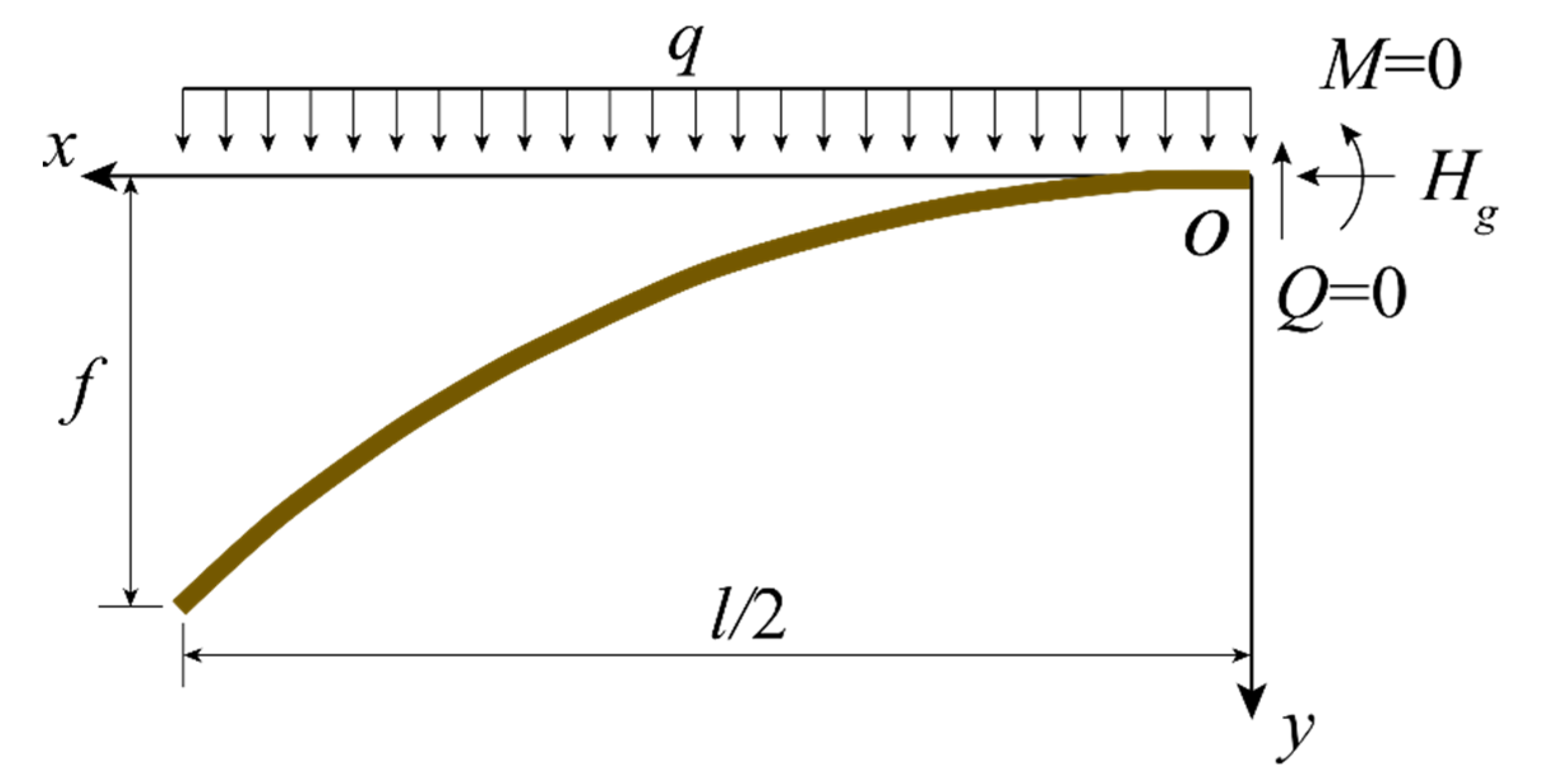
Figure 1. Parabolic arch axis.
Sustainability 14 17043 g001
Figure 2. Catenary arch axis.
Sustainability 14 17043 g002
Figure 3. Ultimate span length of parabolic concrete arch bridge: (a) lmax1; (b) lmax2; (c) lmax3.
Sustainability 14 17043 g003
Figure 4. Ultimate span length of catenary concrete arch bridge: (a) lmax1; (b) lmax2; (c) lmax3.
Sustainability 14 17043 g004
Figure 5. Ultimate span length of concrete arch bridge: (a) Parabolic arch axis; (b) Catenary arch axis.
Sustainability 14 17043 g005
Figure 6. Ultimate span length of parabolic steel arch bridge: (a) lmax1; (b) lmax2; (c) lmax3.
Sustainability 14 17043 g006
Figure 7. Ultimate span length of steel arch bridge: (a) lmax1; (b) lmax2; (c) lmax3.
Sustainability 14 17043 g007
Figure 8. Ultimate span length of steel arch bridge: (a) Parabolic arch axis; (b) Catenary arch axis.
Sustainability 14 17043 g008
Table 1. World record of the main span length for arch bridge.
No.Year of
Completion
Years of
Record
Bridge NameMain Span (m)Rate of IncreaseMaterialCountry
1605695Zhaozhou Bridge37.5——StoneChina
2130041Maddalena Bridge [11]381.3%StoneItaly
3134115Diable Bridge4518.4%StoneItaly
4135621Castelvecchio Bridge498.9%StoneItaly
51377500Trezzo Bridge *7246.9%StoneItaly
618777Maria Bridge160122.2%Cast ironPortugal
718842Garabit Bridge1653.1%Cast ironFrance
8188612Dom Luís Bridge172.54.5%Cast ironPortugal
9189818Upper Steel Bridge *25648.4%Steel trussUSA
10191615Hell Gate Bridge29816.4%Steel trussUSA
11193146Bayonne Bridge [2]50469.1%Steel trussUSA
12197726New River Gorge Bridge5182.8%Steel trussUSA
1320036Lupu Bridge [12]5506.2%Steel boxChina
14200911Chaotianmen Bridge [4]5520.4%Steel trussChina
152020——Pingnan 3rd Bridge [3]5754.2%CFST *China
* Note: Trezzo Bridge collapsed in 1416; Upper Steel Bridge collapsed in 1938; CFST: Concrete Filled Steel Tube.
Table 2. Summary of study on ultimate span of arch bridge.
ResearcherYearMaterialArch AxisRise-Span RatioMaterial GradeUltimate Span (m)MethodCondition
Xia [15,16]2005ConcreteParabolic1/4C60481Theoretical analysisStrength and in-plane stability, solid-web rectangular arch section. An ultimate span reduction coefficient of 0.75 is used for only considering the self-weight of the main arch.
Catenary1/4C60451
SteelParabolic1/4Q345916
Catenary1/4Q345860
Li [17]2007ConcreteCatenary1/5C100590Numerical simulation of archStrength and stability conditions
SteelCatenary1/5Q460660
Wang [18]2012SteelParabolic1/4Q420866Numerical simulation of archStrength and stability conditions
Catenary1/5.5Q420818
Zhao [19]2017ConcreteParabolic1/4C60540Theoretical analysisStrength and in-plane stability conditions. An ultimate span reduction coefficient of 0.62 is used for only considering the self-weight of the main arch.
Tang [8]2017SteelCatenary1/5.55000Theoretical analysisStrength, the allowable stress of steel is 420 MPa
Wang [14]2019CFSTCatenary1/4Q420/C80821Numerical simulation of full bridgeStrength, stiffness and stability conditions
Järvenpää and Jutila [13]2019SteelParabolic1/2.316250Theoretical analysisStrength condition, the allowable stress of steel is 500 MPa
Catenary1/2.968284
Table 3. Calculation length coefficient of out-of-plane stability.
n1/31/41/51/61/71/81/91/10
ζ1.1670.9620.7970.5760.4950.4520.4250.406
Table 4. Ultimate span length in different conditions.
Arch AxisStrength lmax1In-Plane Stability lmax2Out-of-Plane Stability lmax3
Parabola 6.06 λ n 1 + 16 n 2 f d γ 0.0114 λ n 1 + 4 n 2 ( 1 + 8 n 2 / 3 ) 2 E γ 0.2050 λ n 3 ζ 2 ( 1 + 4 n 2 ) 5 2 E γ
Catenary 3.03 λ n k 2 ( m 1 ) 1 + 4 n 2 k 2 m + 1 m 1 f d γ 0.0029 λ k 3 sinh 2 k cosh k 2 E γ 0.0512 λ k n 2 ζ 2 cosh k 2 ( 1 + 4 n 2 ) 2 E γ
Table 5. Design values of compressive strength fd and modulus of elasticity E for concrete.
GradeC60C80R100R120R140R160R180R200
fd (MPa)26.534.648.058.068.077.087.097.0
E (×104 MPa)3.603.804.004.294.524.714.865.00
Table 6. Design strength of steel fd.
GradeQ345Q370Q420Q460Q500Q550Q620Q690
fd (MPa)265285325365380420460520
Table 7. Ultimate span length for concrete arch bridge at n = 1/5.
GradeC60C80R100R120R140R160R180R200
Parabolic arch axis lmax (m)627819113613721609182220582161
Catenary arch axis lmax (m)586766106212831505170419252099
Table 8. Ultimate span length for steel arch bridge at n = 1/5.
GradeQ345Q370Q420Q460Q500Q550Q620Q690
Parabolic arch axis lmax (m)20772233254728602948294829482948
Catenary arch axis lmax (m)19422089238226752785286528652865
Publisher’s Note: MDPI stays neutral with regard to jurisdictional claims in published maps and institutional affiliations.