Abstract
To meet the engineering requirements of long-distance and high-precision elevation transfer under adverse sea conditions, a new structure for a combined survey platform based on the basic principle of vibration reduction and isolation is designed in this paper. The combined survey platform uses the barrier effect of the external support system on the wave-current load to reduce the influence of the wave-current load on the internal support system and the platform, so it can maintain good performance, even in harsh sea conditions, under the premise of no collision between the internal and external support systems. The expected working performance of the structure was verified by numerical simulation, and the influence of the layout, structure size, waves, and water flow on the working performance of the structure was quantitatively analyzed. The results show that: (1) the external support system can better realize the barrier effect of the wave-current load and significantly reduce the influence of the wave-current load on the internal support system and platform; (2) for the independent combined survey platform, when the pile diameters of the internal and external support systems are 0.8 m and 1.2 m and the wall thicknesses are 11.0 mm and 12.0 mm, respectively, the period of the wave is 8.0 s, the water depth is 20.0 m, the speed of water flow is 1.0 m/s, and the wave height is 4.0 m, then the maximum variation of the vertical angle of the platform is only 19.3″; (3) for the attached combined survey platform, the lateral stiffness of the external support system is increased and the displacement of the external support system is significantly reduced because the external support system is connected with the cushion cap through the attachments; therefore, the structure size of the survey platform can be greatly reduced.
1. Introduction
During the construction of large-scale sea-crossing bridge projects, it is necessary to carry out a high-precision sea-crossing elevation transfer to unify the elevation data on both sides of the bridge and accurately transfer the elevation on both sides to the pier and main beam in the sea. Combined with the many sea-crossing bridges that have been built, the precision of the elevation control survey is generally required to meet national second-class survey standards [1]. The corresponding control parameters are that the accidental mean square error of elevation difference per kilometer is ±1 mm and the total mean square error of elevation difference per kilometer is ±2 mm. However, the span of sea-crossing bridges is generally long, as some of these bridges reach several kilometers or even tens of kilometers; therefore, it is extremely difficult to carry out a sea-crossing elevation transfer survey using the conventional leveling method [2,3]. In the project, the elevation control network is generally densified by setting a survey platform in the sea to shorten the survey distance. With the continuous progress of the project, the survey platform is often set on the foundation works, such as the test pile and some piers under priority construction, which greatly shortens the distance measurement [4], creating conditions for the sea-crossing elevation transfer survey using the total station. However, in the actual construction process, due to the influence of the wind, waves, tide, and other factors, the survey platform is always subject to slight shaking, resulting in the vertical angle change range of the total station installed on the survey platform reaching tens of seconds or even minutes [5,6], and the problem is particularly prominent for engineering projects located in strong wave and deep-water area.
At present, the main challenge to realize long-distance and high-precision elevation transfer on the sea is that, under complex sea conditions, the traditional survey platform will have micro-amplitude shaking, which makes the accuracy of elevation difficult to meet the high standard requirements of relevant specifications or standards.
In the previous engineering construction process, the main methods to reduce the impact of external wave-current load (the wave-current refers to waves and currents, which are independent of each other) on the survey were: (1) reducing the shaking amplitude of the survey platform through the designed structure, and (2) reducing the survey error by combining the method based on taking the average value of multiple repeated observations [5,7]. In order to keep the offshore survey platform stable under the impact of wave-current load, the most straightforward method is to increase the stiffness of the platform by increasing the geometric size of the platform. In references [5,8], the sea-crossing elevation survey under the influence of current and waves is carried out directly by increasing the structural stiffness of the survey platform and setting the forced centering observation stand. Practical tests show that the maximum shaking amplitude of the survey platform is still more than under the influence of sea conditions, such as waves and currents. At the same time, the construction cost of a survey platform designed with this concept is huge and even unacceptable when it adapts to the environment of strong waves and deep water. Although the survey error can also be reduced by taking the average value of multiple repeated observations, the method is different from the traditional single survey, and the survey methods and the data processing systems require special design, which is inefficient. In essence, this method assumes that the impact of waves in the survey window period is stable to ensure the statistical stability of the survey data. In fact, waves are mostly unsteady [9], and their impact on the survey platform and the survey reference point is also unsteady, so the statistical survey data itself changes with time. To ensure the accuracy of the survey data, it is necessary to observe for a long time or select an appropriate survey window period. The elevation survey is generally carried out at night [10], which causes obvious interference with the construction.
In view of this, to meet the engineering requirements of a long-distance high-precision elevation transfer under severe wave-current conditions, this paper proposes a combined survey platform suitable for strong wave and deep-water conditions based on the idea of vibration reduction and isolation. A reasonable design is carried out according to engineering practice to ensure the stability of the platform under harsh surge conditions. At the same time, through numerical simulation, the influence of different structural sizes and different sea conditions on the working performance of the combined survey platform is quantitatively studied. The main purpose of the combined survey platform proposed in this paper is to properly reduce the project investment. At the same time, it can make the offshore elevation survey free from the influence of the survey window period, and it can realize fast and accurate real-time offshore elevation monitoring [11]. It is of great engineering and practical significance.
2. Principles and Methods
2.1. Research Background
2.1.1. Project Case
This paper is based on the projects of the Peljesac Bridge in Croatia and the Shenzhen-Zhongshan Bridge in China.
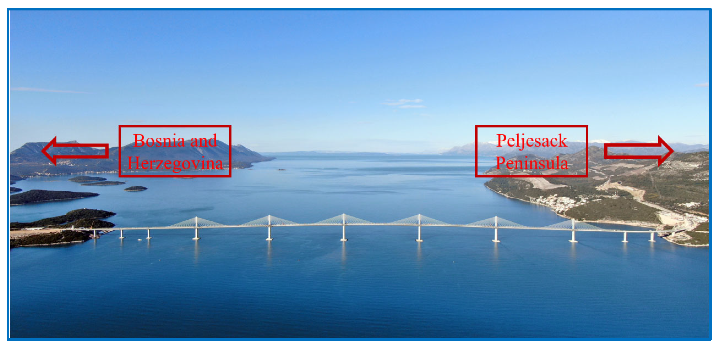
The main bridge of the Peljesac Bridge is a six-tower central single cable plane steel box girder low tower cable-stayed bridge. The total length of the bridge is 2404 m, and its span group is (84 + 108 + 108 + 189.5 + 5 × 285 + 189.5 + 108 + 108 + 84) m. The bridge has 14 piers and abutments in total, including 4 piers and abutments arranged on the land on both banks and the remaining 10 piers and towers arranged in the water, as shown in Figure 1.
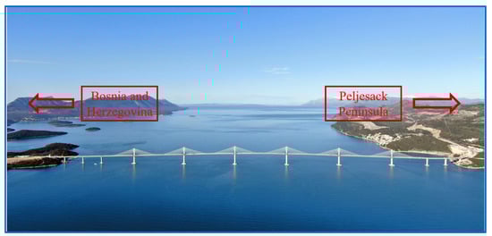
Figure 1.
The layout of the Peljesac Bridge.
The Peljesac Bridge crosses Mariston Bay and the European Union Nature Reserve. It has strict control over the setting of temporary structures in the sea, and the average water depth of the bay at the bridge location is 27 m. The bridge adopts a high pile cap foundation with a soft foundation. During the construction of the bridge, no marine survey platform was set. The elevation transfer is carried out by arranging the survey station on the cushion cap, as shown in Figure 2.
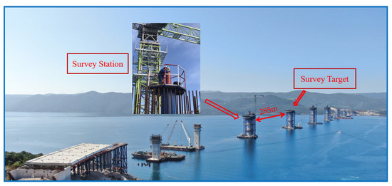
Figure 2.
The offshore survey layout of the Peljesac Bridge.
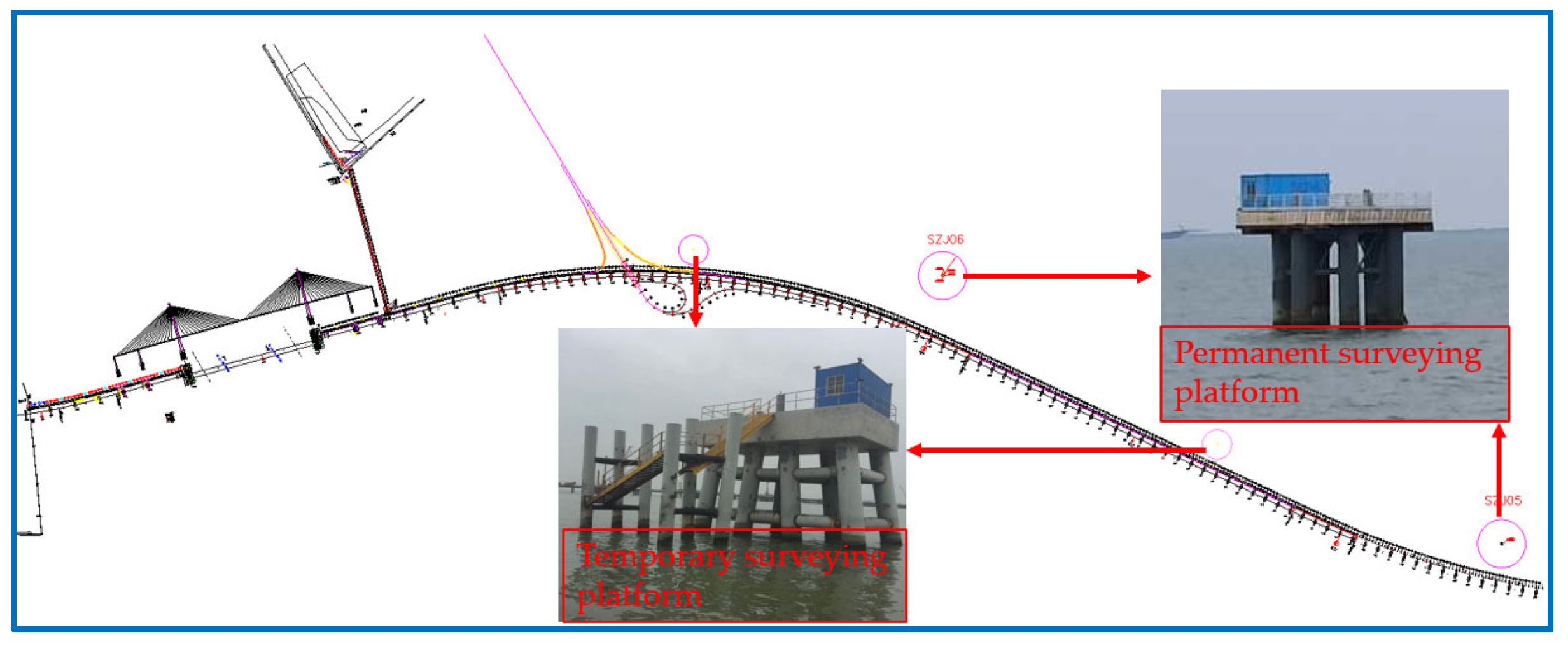
The Shenzhen-Zhongshan Bridge is located in the middle of the Pearl River in the core area. It is a bridge under construction that connects Shenzhen City and Zhongshan City in Guangdong Province, and it has a total length of 24 km. To meet the needs of the construction survey, two permanent survey platforms and two temporary survey platforms are set up, as shown in Figure 3.
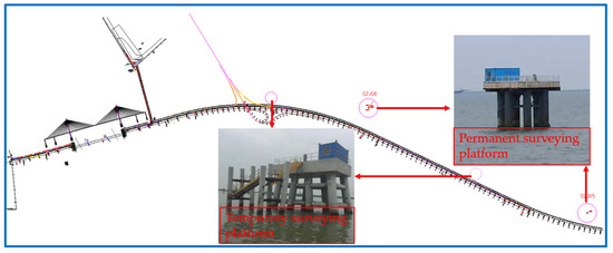
Figure 3.
The survey platform layout of the Shenzhen-Zhongshan Bridge.
2.1.2. Working Performance Test
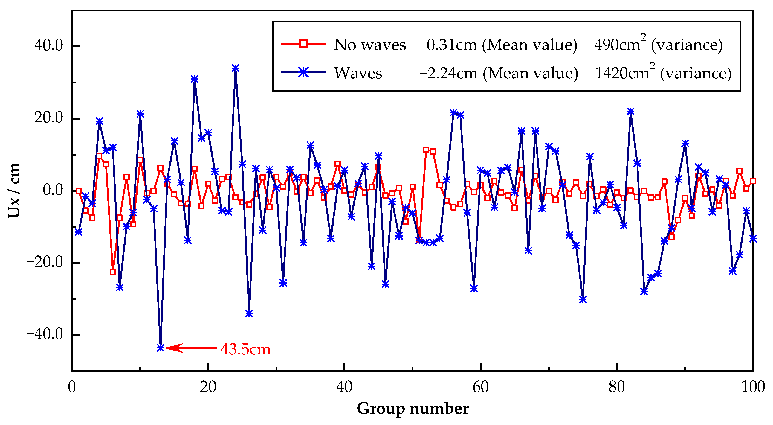
Due to the influence of the waves, the water flow, and the tide, the survey instruments placed on the pier, the cushion cap, and the separately set survey platform each shake greatly during the working period. Figure 4 and Figure 5, respectively, show the changes in the instrument coordinates and the vertical angles of a total station set on a cushion cap in the sea that were caused by the sea conditions present during the construction of the Peljesac Bridge.
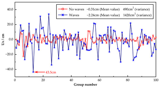
Figure 4.
The coordinate changes in the survey instrument.
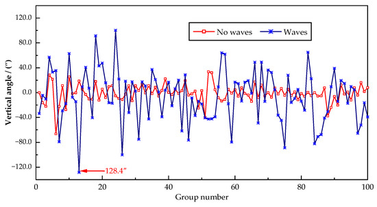
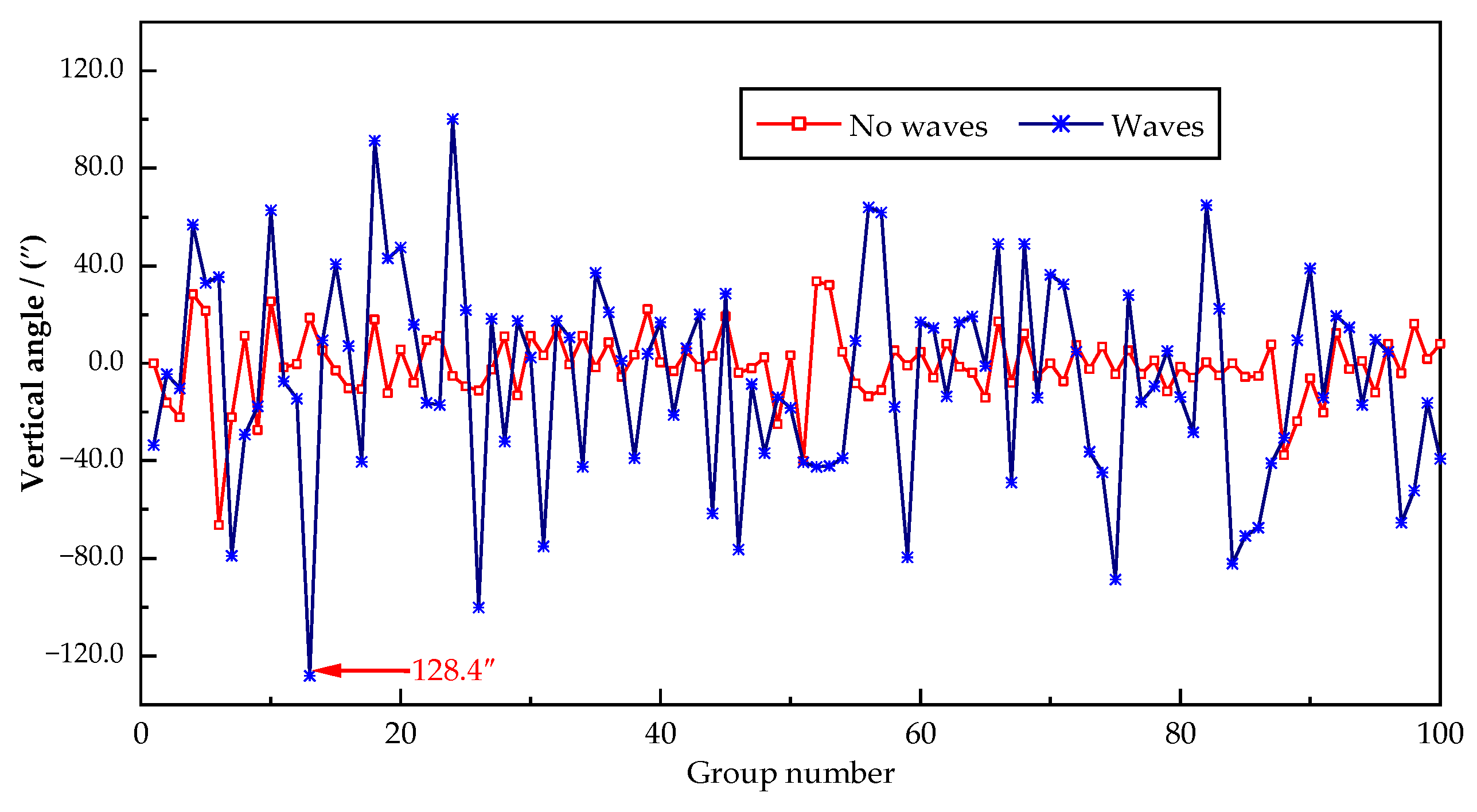
Figure 5.
The vertical angle changes in the survey instrument.
The changes in the coordinates and the vertical angles of the measuring instrument under the conditions of waves and no waves show that:
- (1)
- The shaking of the survey platform is relatively significant due to the impact of the wave current, and the maximum coordinate change in the survey instrument in the direction of wave propagation can reach about 43.5 cm, with a corresponding vertical angle change value of 128.4″.
- (2)
- Compared with the condition of waves, the working performance of the survey platform is more stable under the condition of no waves, and the change in the coordinates and the vertical angle in the survey instrument is relatively small.
2.2. The Principle of Design
For the previous survey platform, the wave-current load on the platform is borne by the pile foundation. When the sea conditions are relatively bad, the survey platform will shake to some extent, which affects the survey accuracy of the total station erected on it.
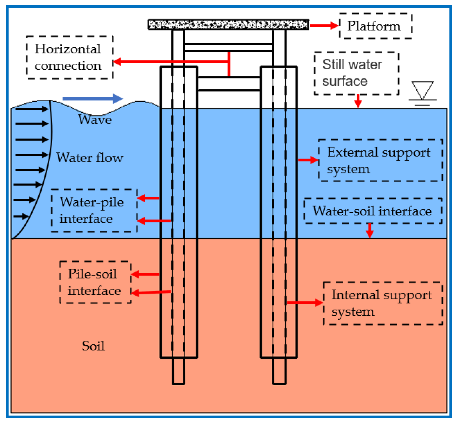
Based on the basic principle of vibration reduction and isolation, this paper designs a new structure for a combined survey platform, and its principle of design is shown in Figure 6. The combined survey platform is composed of internal and external support systems and platforms, and the internal and external support systems are independent of each other in terms of load. The external support system directly bears the wave-current load, while the internal support system is not directly affected by the wave and water flow. It only bears the load imposed by the top platform and the load transmitted by the water and the soil between the internal and external support systems so the combined survey platform can maintain stability even under adverse sea conditions.
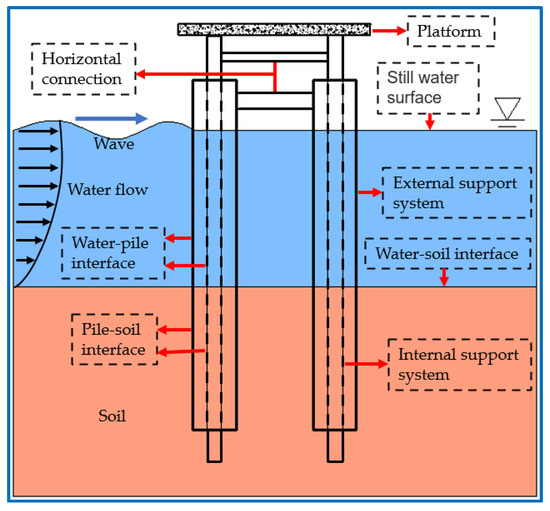
Figure 6.
The design principle of the combined survey platform.
According to the different functions of the internal and external support systems, the corresponding structural dimensions need to be designed separately. The larger the inner diameter of the external support system is, the greater the rigidity. Additionally, the larger the gap between the external support system and the internal support system is, the less likely it is that the internal support system will touch the external support system, but this will increase the investment of the entire survey platform. At the same time, with the increase in the inner diameter of the external support system, the wave-current load on the external surface increases correspondingly. Selecting the appropriate stiffness and geometric size while meeting the needs of the working performance is an important measure to achieve the dual goals of applicability and economy.
2.3. Design of the Layout Scheme
According to the different layouts, the design of the combined survey platform can be divided into two schemes: independent and attached.
2.3.1. The Independently Set Combined Survey Platform
Since the construction of sea-crossing bridges is mostly in wide sea areas, the survey platform needs to work as an independent structure. Therefore, the loads caused by waves and water flow are all borne by the survey platform. The rigidity of the traditional survey platform should be strong enough to meet the high standard requirements of survey instruments for the stability of the survey platform. The direct problem is a large amount of investment, and the economy of engineering construction cannot be guaranteed. For the combined survey platform proposed in this paper, because its external wave-current load is completely loaded onto the external support system and the internal support system only bears the load generated by the upper platform and the load transmitted by the soil and the water between the internal and external support systems, its stability does not need to be ensured by greatly increasing the rigidity of the structure like the traditional survey platform, but the high standard working performance requirements of the survey platform are realized.
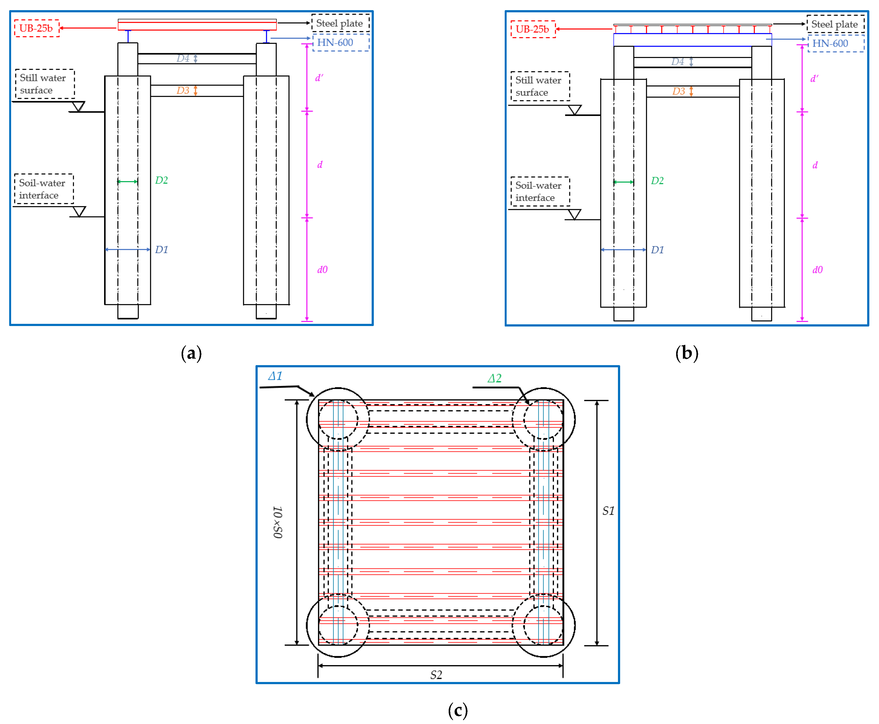
For the upper platform part of the independently set combined survey platform, two HN-600 load-bearing beams can be set on top of the internal support system. UB-25b distribution beams with a spacing of 488 mm are placed on the load-bearing beams. Fifteen mm thick steel plates are laid on the distribution beams. The design drawing is shown in Figure 7.
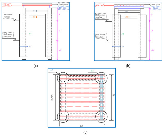
Figure 7.
The design drawing of the independently set combined survey platform. (a) The elevation view of the survey platform. (b) The side view of the survey platform. (c) The vertical view of the survey platform.
and are the diameters of the external and internal support systems, respectively; and are the diameters of the external lateral connection and the internal lateral connection, which are 0.8 m and 0.4 m, respectively, and their thicknesses are 0.01 m; is the penetration depth of the internal and external support systems in the soil, which are 30 m and 25 m, respectively; is the height from the still water surface to the seabed, taken as 20 m; is the distance from the top of the internal and external support systems to the still water surface, taken as 5 m and 4 m, respectively; is the spacing between the distribution beams, taken as 0.448 m; and are the length and the width of the platform, which are both 5 m; and and are the thicknesses of the external and internal support systems, respectively.
2.3.2. The Attached Combined Survey Platform
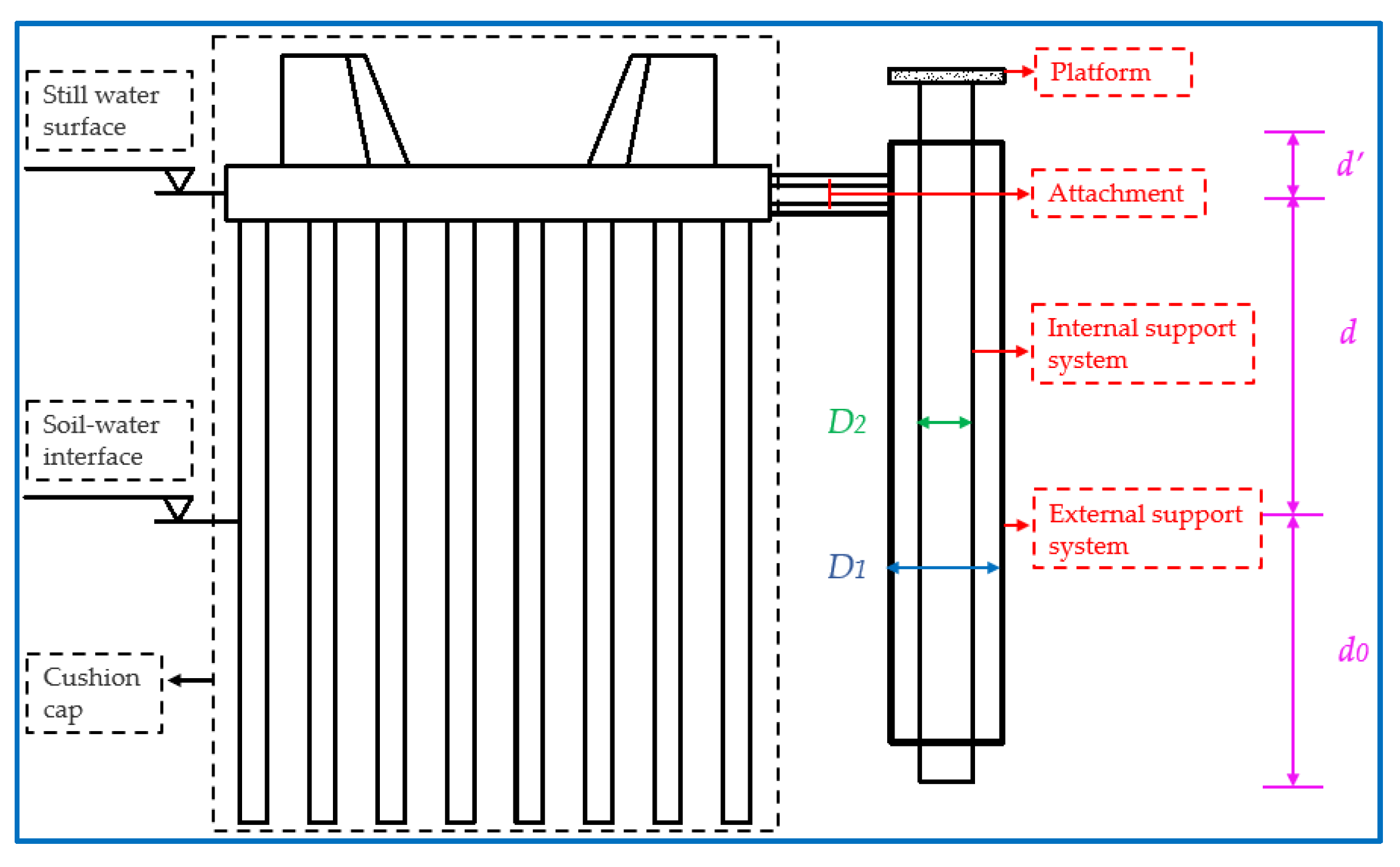
The survey and positioning accuracy of the pile foundation and the cushion cap is lower. In the early stage of the project, cross-water surveys can be carried out by GNSS and other methods. When the construction of the cushion cap is completed, the external support system of the combined survey platform can be attached to the cushion cap through attachments (a steel pipe or other structures with sufficient rigidity). The stiffness of the cushion cap can make up for the deficiency in the stiffness of the external support system so the external support system will not shake significantly under the wave-current load. The cushion cap will shake to a certain extent under the wave-current load, and if the internal support system is also connected with the cushion cap, the shaking will have a negative impact on the working performance of the independent combined survey platform; therefore, the internal support system will not be connected with the cushion cap. At the same time, the attached combined survey platform can be a single-pile platform. The gap between the external support system and the internal system can be properly reduced. The design drawing is shown in Figure 8.
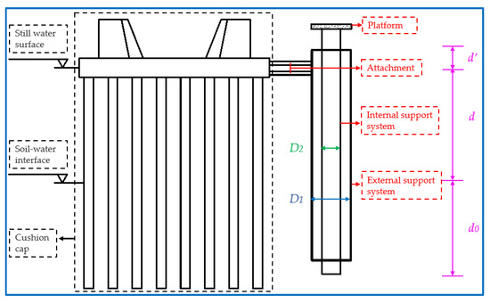
Figure 8.
The design drawing of the attached combined survey platform.
Where the parameters in the figure have the same meanings as those in Figure 7.
2.3.3. Project Cost Comparison
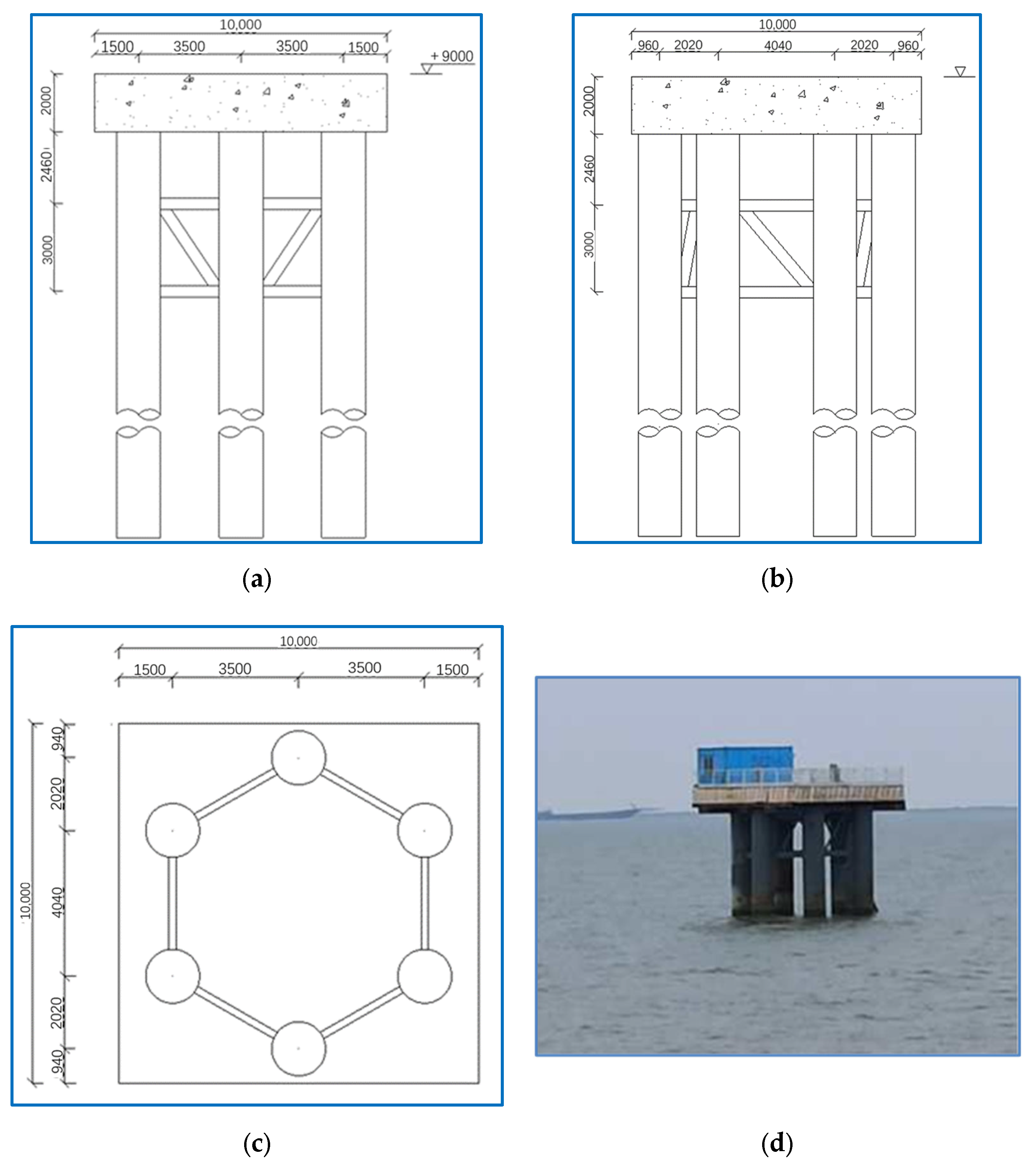
In order to make an approximate evaluation of the project cost required for the combined survey platform designed in this paper, the materials required for the construction of the independently set combined survey platform and the permanent survey platform (as shown in Figure 9) in project case 2 are compared. The steel pipe piles of the platform shown in Figure 9 are all , and the size of the concrete platform is . The structural dimensions of the external and internal support systems of the independently set combined survey platform are: , , , .
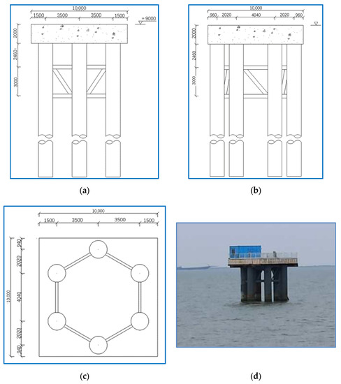
Figure 9.
The permanent survey platform. (a) The elevation view. (b) The side view. (c) The vertical view. (d) The general arrangement plan. Note: All dimensions in the figure are in millimeters.
The comparison of material consumption is shown in Figure 10. It can be seen from the figure that the traditional survey platform needs to provide enough stiffness to resist the impact of the external wave current load, so its structure size is often large, and the required engineering investment is more than that of the combined survey platform proposed in this paper.
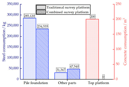
Figure 10.
The comparison of material consumption.
2.4. Dynamic Equations and Boundary Conditions
This section describes the dynamic equations and boundary conditions used in the numerical simulation in Section 2.6.
2.4.1. Governing Equation of Water
It is assumed that the fluid is a compressible, small-disturbance fluid without rotation and viscosity. The governing equation of water, represented by the velocity potential of water, φ, is
where is the speed of sound in water, , and when the compressibility of the water is neglected; K is the bulk modulus of water [12]; is the water density; and is the time.
2.4.2. Governing Equations of Soil and Pile
According to the basic equations of elastodynamics, the governing equations of soil and pile can be expressed as
where is the vector differential operator of rectangular coordinates; and are the lame constant; and , , and are the displacements of soil and pile in , , and directions respectively.
2.4.3. Surface Boundary Conditions of Water
The pressure on the free surface of still water is equal to the atmospheric pressure. For simplicity of the following calculation,
the hydrodynamic pressure at any time and space can be expressed as
where is the hydrodynamic pressure of water.
If a small amplitude wave is formed on the free surface of the water, the gravity wave included in the analysis shall be considered through the linear surface wave condition [13]. The pressure on the surface can be expressed as
The above equation can be expressed as
2.5. Calculation of Wave-Current Load
In addition to the load generated by the wave, the offshore structure is often acted upon by the current load generated by the water flow. Therefore, when analyzing the response of the structure under the action of the sea conditions, the wave load and the current load should be considered together. In this section, the wave parameter calculation model and the model of current velocity varying with water depth used in the numerical calculation in Section 2.6 are described.
2.5.1. Wave Parameter
Waves can be divided into regular and irregular waves according to their shapes. The waves that propagate freely after leaving the wind zone are close to regular waves, while the wind waves in the ocean are irregular. The regular linear wave theory is selected as the wave theory in this paper, and the expression of the wave surface equation is
where is the wave height and is the wave number.
The strong wave and deep-water conditions described in this paper are defined according to the international wave level table (as shown in Table 1) and the micro amplitude wave theory.

Table 1.
The international wave level table.
According to the micro amplitude wave theory, wave types can be divided as follows.
The deep-water wave:
The finite depth wave:
The shallow water wave:
where is the wavelength and is the water depth. In engineering, d = 0.5 L is often used as the boundary between infinite water depth and finite water depth.
The dispersion equation of linear waves is
where and .
After the period is determined, the wavelength can be solved through the above dispersion equation, and vice versa. Many scholars have put forward some approximate methods for a direct solution to the above equations. In this paper, the following calculation (Formula 14 ), proposed by Vatankhah and Aghashariatmadari [14] through numerical analysis, is used to solve them.
Under any water depth condition, the maximum relative error of the formula is less than 0.019%.
2.5.2. The Flowing Speed Model of Seawater
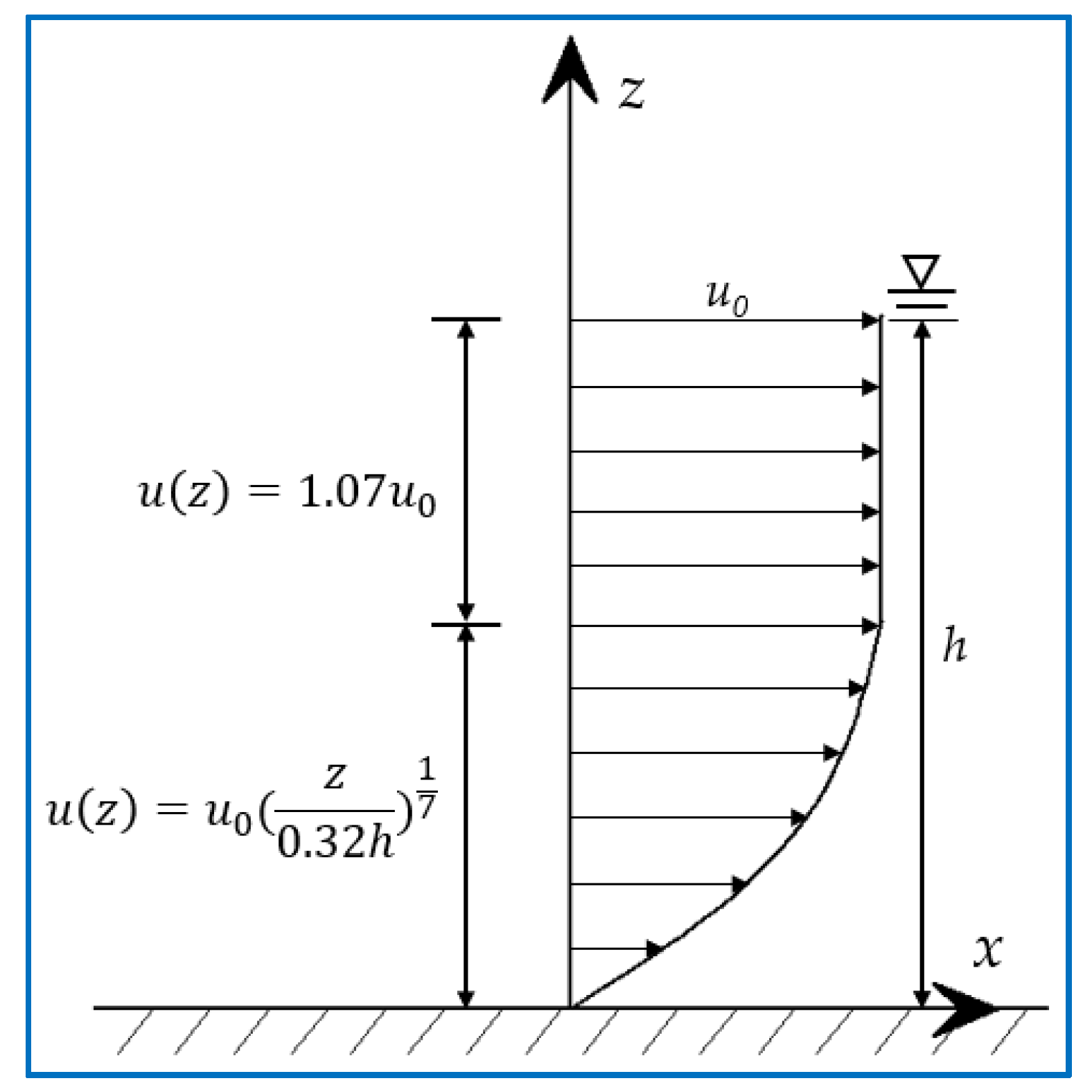
In the direction perpendicular to the sea level, the speed of the seawater flow changes with the depth of the seawater. Generally, the speed changes from the sea level to the seabed in a regular manner of “large up and small down.” In this paper, the 1/7 exponential rate distribution model [15], proposed by Soulsby, is adopted. The model divides the vertical distribution of the flow speed into two layers for calculation. The upper layer adopts a linear distribution, and the lower layer adopts an exponential distribution. The schematic diagram of the model is shown in Figure 11. The vertical distribution of flow speed is given by
where is the velocity of the seawater surface, .
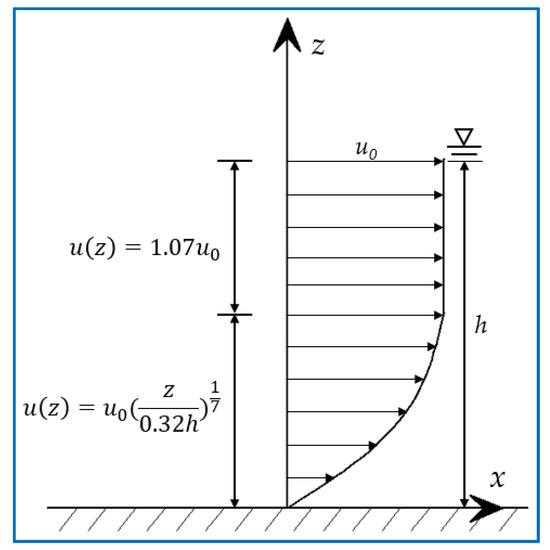
Figure 11.
The flowing speed model of seawater in the direction of water depth.
2.5.3. Wave-Current Load
There are many methods used to calculate the wave-current load [16,17]. In this paper, the nonlinear wave force [18] is not considered. The Morison formula with current participation is used to calculate the wave-current load on the pile. The wave-current load is given by
where is the wave-current load on a unit length micro-segment at any height of the pile, ; is the sectional area of the pile, ; is the drag coefficient; is the inertia force coefficient; is the weight of the water, ; is the horizontal acceleration of the orbital motion of the water particles, ; is the total horizontal velocity of the water particles, ; is the flow speed of the water, ; and u is the flow speed of the water particles generated by waves, .
2.5.4. Hydrodynamic Coefficient
The values of the two hydrodynamic coefficients in the Morison formula, namely the drag coefficient and the inertia force coefficient , are related to the accuracy of the final calculation results. For the values of these two coefficients, local scholars and scholars abroad have done a lot of experimental research, and they have given many recommended values in relevant papers, as well as specifications for reference in engineering practice. In general, if we want to get more accurate results, we must carry out hydrodynamic experiments in the actual water area to determine the value of the correlation coefficient. In this paper, the and values are determined according to references [19,20]. Finally, the is taken as 1.2, and the is taken as 2.0.
When calculating the wave-current load on the pile foundation of offshore structures, if the relative pile distance ( is the pile center distance and D is the pile diameter) is small, the blocking effect of the pile array on the wave-current will increase the flow speed at the pile foundation, and the pile group effect cannot be ignored. When ≥ 3.0, the pile group effect is weak, and the impact can be ignored [21].
2.6. Numerical Simulation
2.6.1. Method
In this paper, the Coupled Acoustic-Structure approach (CAS) is used for numerical simulation analysis in the finite element software ABAQUS. The acoustic wave control equation expressed by the acoustic pressure p as an independent variable is also called the Helmholtz equation, which is given as
where is the speed of sound in the liquid, , and k is the bulk modulus of the liquid.
The advantage of using the CAS approach for modeling is that it is relatively simple and effective for numerical processing because it assumes no material flow, so no mesh deformation occurs. In addition, since the acoustic element has only pressure freedom at each node, it significantly reduces the computational time required for simulation [22].
The impedance boundary condition is defined on the free surface of the acoustic element using linear wave theory. The boundary impedance relates the pressure of the acoustic element to the normal motion at the acoustic structure interface. The speed () of acoustic particles in the direction of the external normal of the fluid surface is related to the pressure and the rate of change in the pressure over time, which is given as
where is the acoustic pressure; is the change rate of sound pressure with time; is the ratio coefficient between the acoustic pressure and the displacement in the normal direction of the surface; and is the ratio coefficient between the acoustic pressure [23].
2.6.2. The Finite Element Model
In the modeling and numerical analysis of the combined survey platform shown in Figure 7, acoustic elements are used to simulate the internal and external support systems and the water between the support systems [24,25,26]. The internal and external support systems are simulated by shell elements, and the seabed is simulated by solid elements. The simulation of the water-pile and water-soil interfaces is realized by “tie” constraints, and the simulation of the pile-soil interface is realized by “embedded” constraints. The interaction between the platform and the distribution beam above the internal support system is defined by “tie” constraints in the software [27], and the analysis program uses dynamic implicit analysis. The parameters of pile and soil in the model are shown in Table 2.
Table 2.
The parameters of the model.
During the shaking process in the water between the internal and external support systems, gravity is essential for resilience, but it is not allowed to directly define the uniformly distributed gravity load in the acoustic elements. In order to solve this problem, the acoustic impedance is introduced [22]. In the “geostatic step” of the model, the hydrostatic pressure corresponding to the water depth should be applied to the soil, and the treatment of the stress balance should be carried out by introducing the stress field. The wave-current load caused by the wave and water flow on the external support system is loaded by using the time history load obtained by the calculation method described in Section 2.5.3. The modeling process is shown in Figure 12.
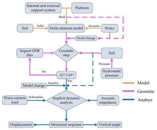
Figure 12.
The flow chart of the numerical simulation modeling. * Note: is the displacement in the depth direction of the soil in the geostatic step.
2.6.3. The Development and Verication of Subroutine
The “AQUA” module in ABAQUS can only calculate the wave-current load on small-scale structures, and the model element can only be calculated by the beam element. To load the combined survey platform proposed in this paper with the wave-current load, the load on the beam element is converted to the shell element by the principle applied in reference [29], and then the subroutine “Utracload” is compiled in the Fortran language to load the corresponding load.
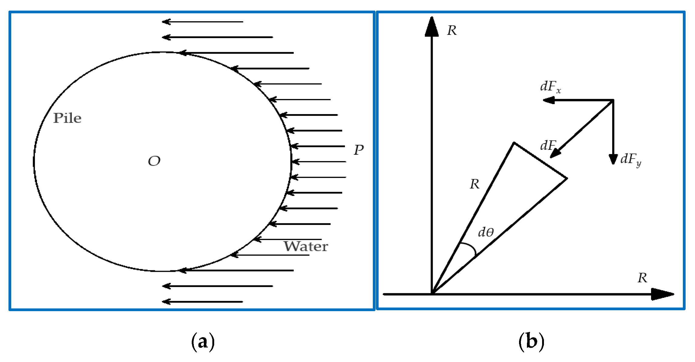
The principle applied in this process is: assuming that the pressure P is uniformly distributed on the half circumference of the pile, which is the surface facing the direction of the wave, the resultant force of the pile in the x direction is the total wave load on the pile, and the resultant force of the pile in the y direction is 0 [29]. The calculation principle is shown in Figure 13. Reference [29] has studied the rationality of this method. The research results show that the method can be used to simplify the wave load on small-scale structures, and the accuracy of the calculation results fully meets the engineering requirements.
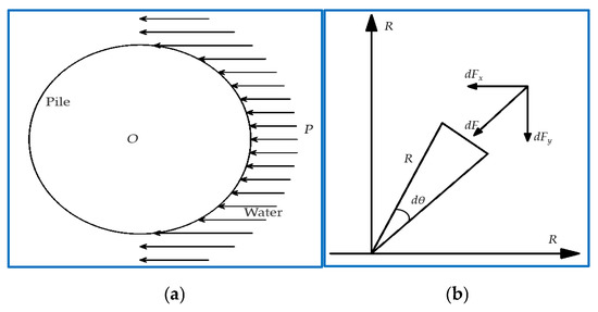
Figure 13.
The conversion principle of the wave-current load on the shell element.
The expression of the wave-current load on the shell element is given as
where represents the angle between the axis and the line connected by the wave propagation direction and the center of the steel pipe. Its function is to decompose the wave force of the steel pipe pile along the axis and the axis, respectively.
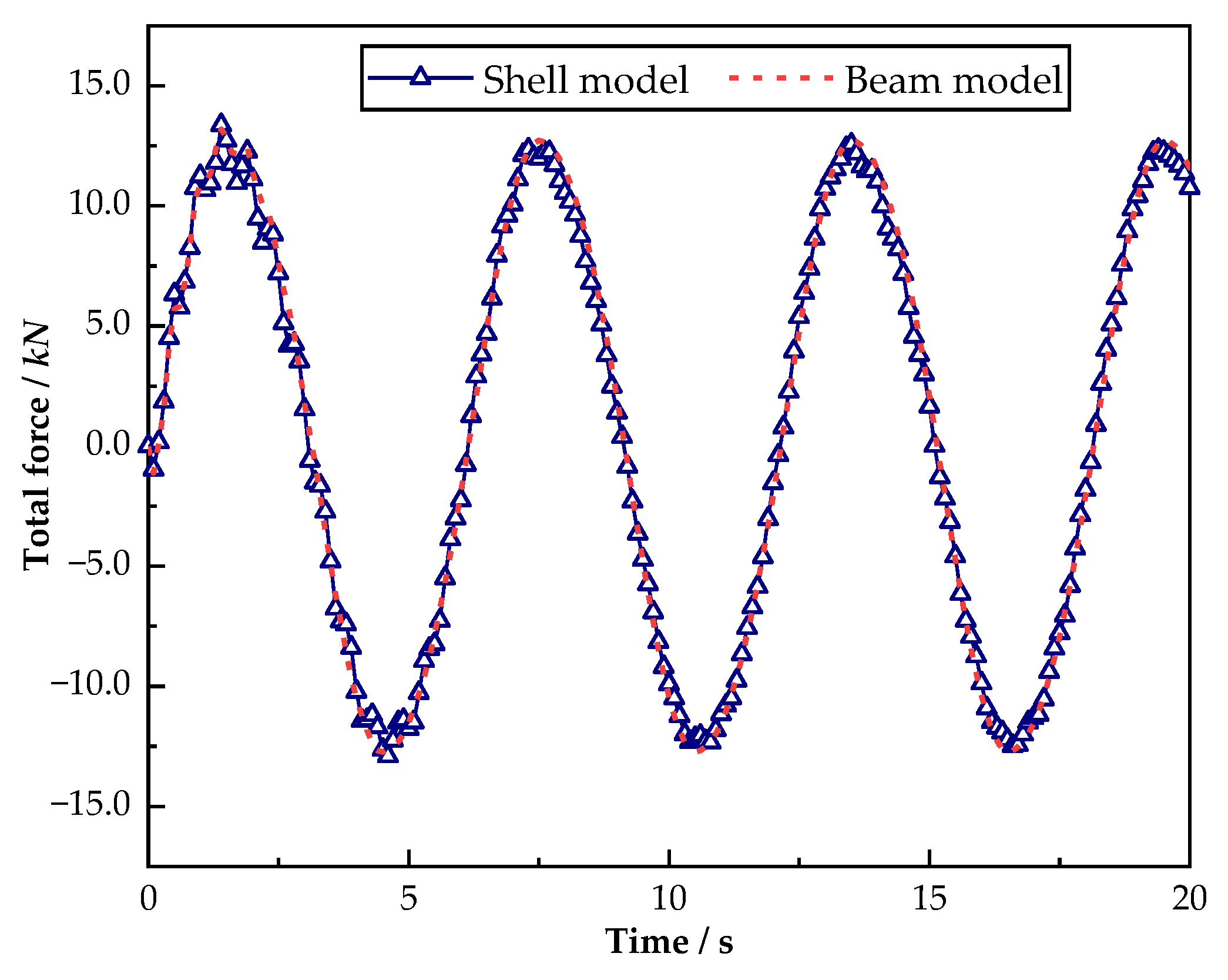
To verify the accuracy of the load subroutine, the beam element and the shell element are used to establish models for the steel pipe pile with a diameter of 1 m and a pile length of 20 m in ABAQUS, respectively, and contrast analysis of the two models in the wave height of 1 m, a period of 8 s wave conditions, and the steel pipe piles by the total difference of wave load. Among them, the beam element model uses the “AQUA” module to load the wave load, and the shell element model uses the above-mentioned load subroutine to load the wave load calculated by the theoretical formula. The total wave load received by the beam element model is the support reaction force received by the pile bottom in the wave propagation direction, while the shell element model is the sum of the support reaction forces received by each node at the pile bottom in the wave propagation direction. The comparison of the results is shown in Figure 14.
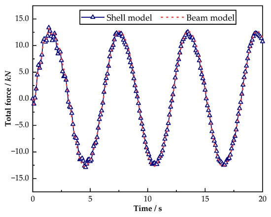
Figure 14.
The comparison of the results.
It can be seen from the comparison of the two models shown in Figure 14 that the results obtained by the shell element and the beam element are the same. This shows that the principle of the method used to convert the wave load on the beam element into the shell element is reasonable, and it also verifies the correctness of the Fortran subroutine written in this paper.
3. Analysis of Working Performance
Based on the basic principle of vibration reduction and isolation, a new structure for a combined survey platform is proposed in this paper. Two kinds of layout designs are carried out according to the different positions of the survey platform: independent and attached. Quantitative research is carried out to understand the specific effects of the structural size and the sea conditions on the working performance of the combined survey platform.
For the convenience of expression, the pile diameter and the wall thickness mentioned below refer to the combination of the pile diameter and the wall thickness of the external support system, and the platform described is the survey platform on the top of the internal support system.
3.1. The Working Performance of the Independent Layout Scheme
According to the different roles played by the internal and external support systems in the process of quantitative research on the independently set combined survey platform, six combination schemes are designed according to the different structure sizes, as shown in Table 3.
Table 3.
The schemes of size combinations.
3.1.1. The Structural Response of the Independently Set Combined Survey Platform
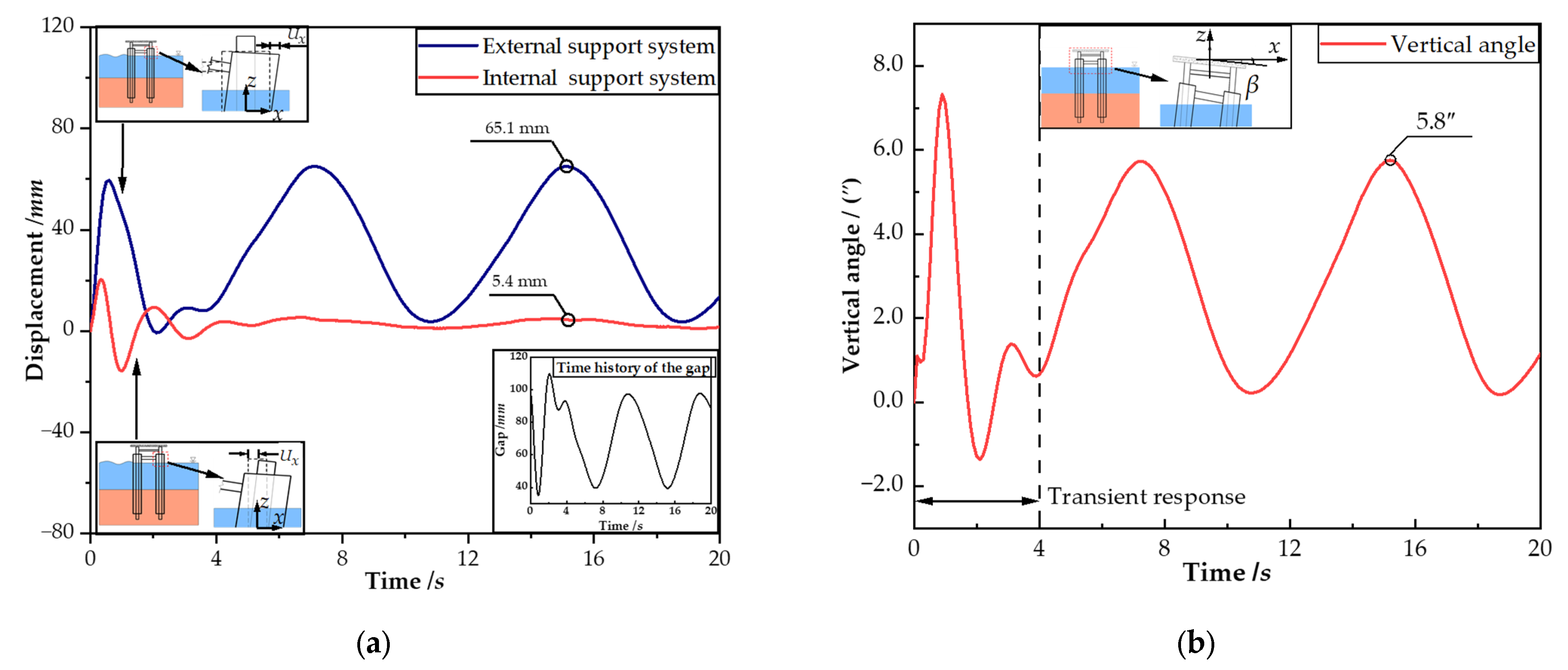
In order to verify the working performance of the independently set combined survey platform under the wave-current load, the wave height, the wave period, the speed of the water flow, and the water depth are set as 1.0 m, 8.0 s, 1.0 m/s, and 20.0 m, respectively. The time history of the wave-current load is loaded on the survey platform mentioned in Scheme 2 in Table 3. Figure 15a shows the displacement variation time history of the free end of the internal and external support systems. As the figure shows, under the action of the wave-current load, the variation amplitude of the displacement of the external support system is large, with a maximum value of up to 65.1 mm, while the variation amplitude of the displacement of the internal support system is significantly reduced compared to the external support system, and the maximum displacement is only 5.4 mm.

Figure 15.
The time history of structural response. (a) The displacement of the internal and external support systems. (b) The vertical angle of the platform.
The gap between the internal and external support systems can be expressed as
where is the gap between the internal and external support systems, ; is the diameter of the external support systems, ; is the diameter of the internal support systems, ; is the displacement of the external support system, ; and is the displacement of the internal support system, .
The subgraph in Figure 15a shows the time-history curve of the gap between the internal and external support systems. The large difference in displacement between the internal and external support systems indicates that: (1) the external support system achieves the expected barrier effect to the wave-current load, and the internal support system only bears the load transferred by soil and water quality between the internal and external support systems, which can significantly reduce the wave-current load on the influence of the internal support system; and (2) since the displacement of the internal support system is small, whether the internal and external support systems collide is mainly affected by the displacement of the external support system. Figure 15b shows the variation time history of the vertical angle of the independently set combined survey platform. As the figure displays, under the action of the wave-current load, the variation amplitude of the vertical angle of the platform is small, and the maximum value of the vertical angle is only 5.8″, which proves that the independently set combined survey platform designed in this paper still has a good working performance under the influence of the wave and the current.
The prerequisite for the good working performance of the combined survey platform proposed in this paper is that the internal and external support systems do not collide. Additionally, since the displacement of the internal support system is small compared to the displacement of the external support system, the quantitative research carried out in the following is evaluated by the displacement of the external support system and the vertical angle of the top platform.
3.1.2. The Influence of Sea Conditions
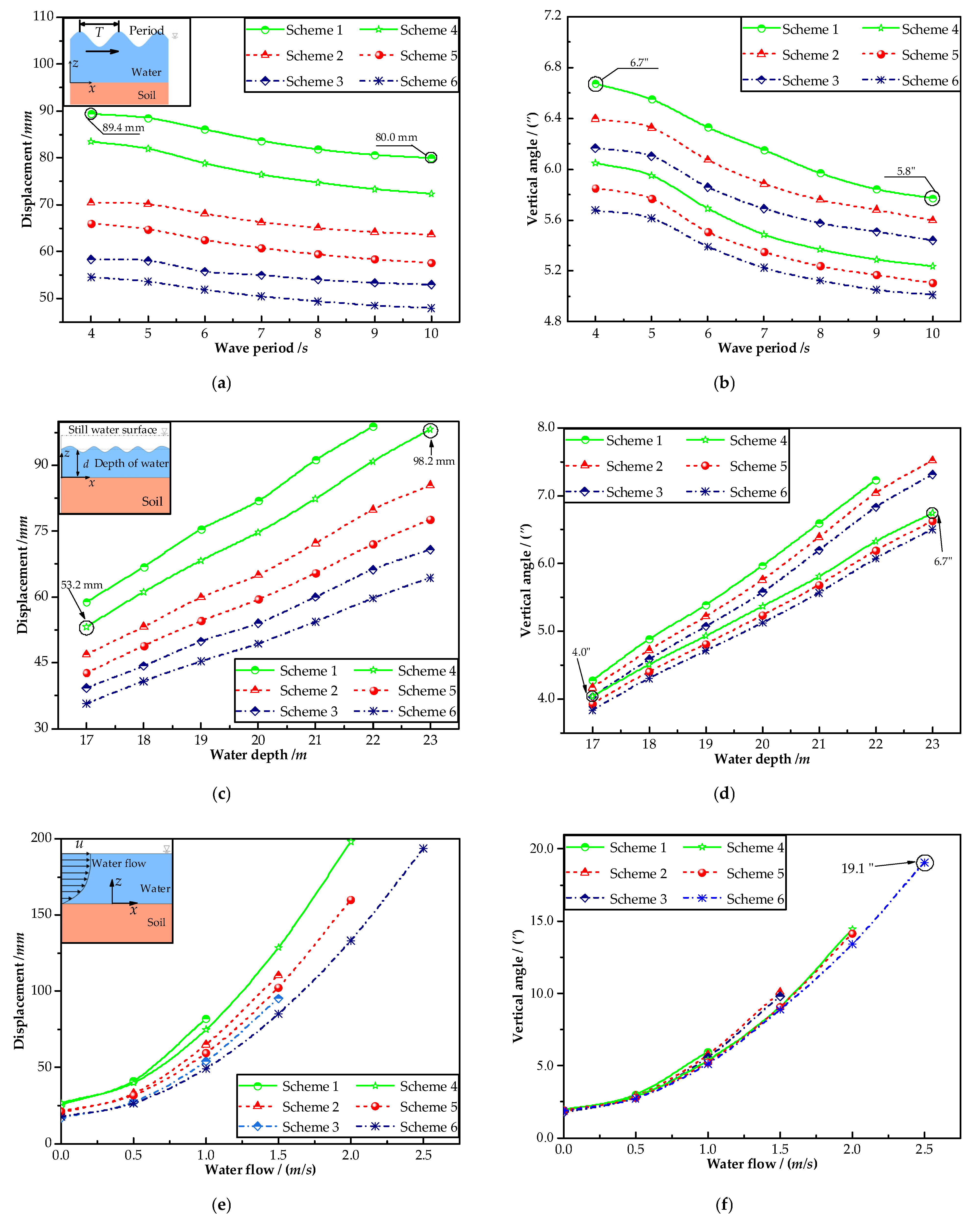
To study the influence of the wave-current period on the working performance of the independently set combined survey platform, the wave height, the velocity, the water depth, and the wave-current period are set as 1.0 m, 1.0 m/s, 20.0 m, and 4.0–10.0 s, respectively. Then, the wave-current load is loaded on the survey platform with different structure size combination schemes. Figure 16a,b shows the influence of the maximum displacement of the external support system and the maximum vertical angle of the platform by the wave-current period. As shown in the figure, for the same combined survey platform model, the maximum displacement of the external support system and the maximum vertical angle of the platform gradually decrease with the gradual increase of the wave-current period, but the decreasing trend is relatively gentle. In general, the variation of the wave-current period has little influence on the working performance of the independently set combined survey platform. When the wave-current load is the same, the model results with different structural sizes have certain differences. By increasing the pile diameter or the wall thickness, the displacement of the external support system can be reduced to a large extent, but the change in the vertical angle of the platform is small.
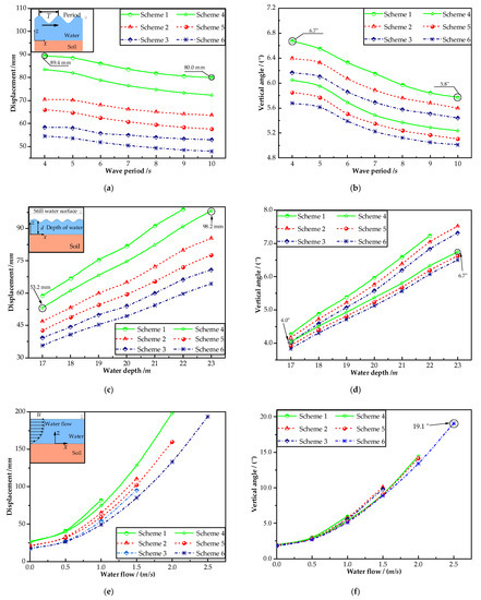
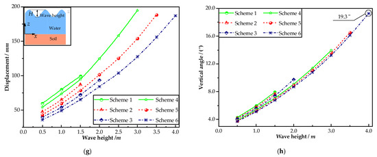
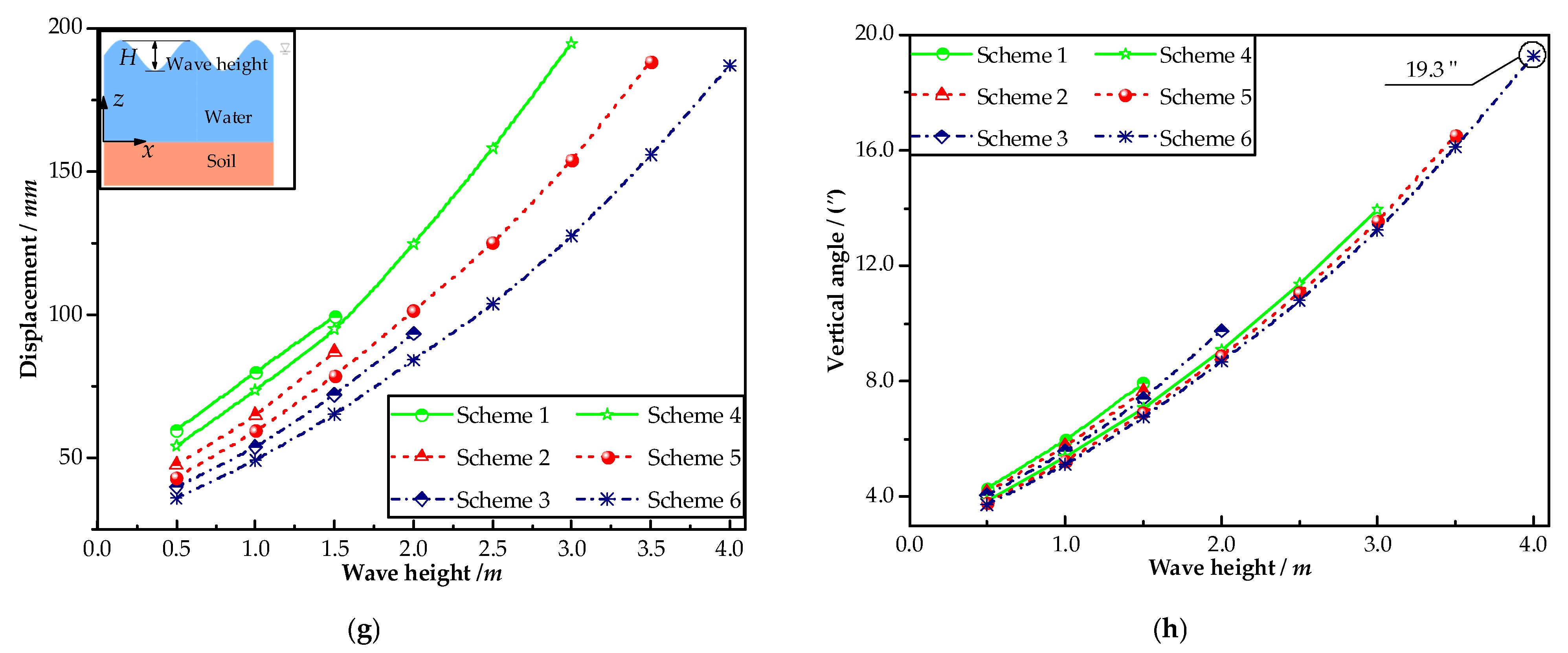
Figure 16.
The most unfavorable effect of sea conditions on the working performance of the dependently set combined survey platform. (a,c,e,g) The maximum displacement of the external support system. (b,d,f,h) The maximum vertical angle of the platform.
Due to the influence of tides, the water depth at the location of the survey platform will change constantly. The wave height, the speed of the water flow, the wave-current period, and the water depth are set as 1.0 m, 1.0 m/s, 8 s, and 17.0~23.0 m, respectively. The most unfavorable effects of the water depth on the working performance of the dependently set combined survey platform are shown in Figure 16c,d. The figure highlights that the maximum displacement of the external support system and the maximum vertical angle of the platform basically show a trend of linear increase with the increase in the water depth. An increase in the water depth from 17 m to 23 m results in a change in the maximum displacement of the external support system of about 45 mm and a change in the maximum vertical angle of the platform of about 2.7”. When the wave-current load is the same, the displacement of the external support system can be reduced, to a large extent, by increasing the pile diameter or the wall thickness, but the magnitude of the change in the vertical angle of the platform is relatively small.
In order to quantify the influence of the water flow on the working performance of the independently set combined survey platform, the wave height, the wave-current period, the water depth, and the water flow speed are set as 1.0 m, 8.0 s, 20.0 m, and 0~2.5 m/s, respectively. Figure 16e,f respectively show the influence of the maximum displacement of the external support system and the maximum vertical angle of the platform by the water flow speed. It can be seen from the figure that the water flow speed has a great influence on the performance of the independently set combined survey platform. With the increase in water flow speed, the maximum displacement of the external support system and the maximum vertical angle of the platform increase significantly. Due to the large displacement of the external support system, the gap between the internal and external support systems should be increased accordingly to avoid a collision between the internal and external support systems. As shown in the figure, by increasing the pile diameter and the wall thickness of the external support system, the independently set combined survey platform can still work normally at a water flow speed of 2.0 m/s, and the maximum vertical angle of the platform is not more than 20″. It is thus clear that the independently set combined survey platform is sensitive to the influence of the water flow speed. It has a good effect by changing the structure size to reduce the displacement of the external support system and prevent collisions between the internal and external support systems under the influence of large water flow speeds, but the impact on the vertical angle is relatively small.
To clarify the influence of the wave height on the working performance of the independently set combined survey platform, the period, the water depth, the water flow speed, and the wave height are set to 8 s, 20 m, 1.0 m/s, and 0.5~4.0 m, respectively. Figure 16g,h respectively show the influence of the maximum displacement of the external support system and the maximum vertical angle of the platform by the wave height. As the figure shows, due to the gradual increase in wave height, the maximum displacement of the external support system and the maximum vertical angle of the platform both increase significantly, and the possibility of collision between the internal and external support systems also increases accordingly. The internal and external support systems need to provide a larger gap to avoid a collision. As shown in the figure, by increasing the pile diameter and the wall thickness of the external support system, the displacement of the external support system can be significantly reduced, and the collision between the internal and external support systems can be effectively prevented, but it has little effect on the vertical angle of the platform.
3.2. The Working Performance of the Attached Layout Scheme
The displacement of the external support system caused by the wave-current load in the direction parallel to the attachments is small for the attached combined survey platform. Therefore, the influence of the wave-current load in the direction perpendicular to attachments on its working performance is studied in this paper. As shown in Table 4, according to different combinations of sizes, nine layout schemes are designed.
Table 4.
The schemes of the size combinations.
3.2.1. Effect Verification of Attachment Layout Scheme
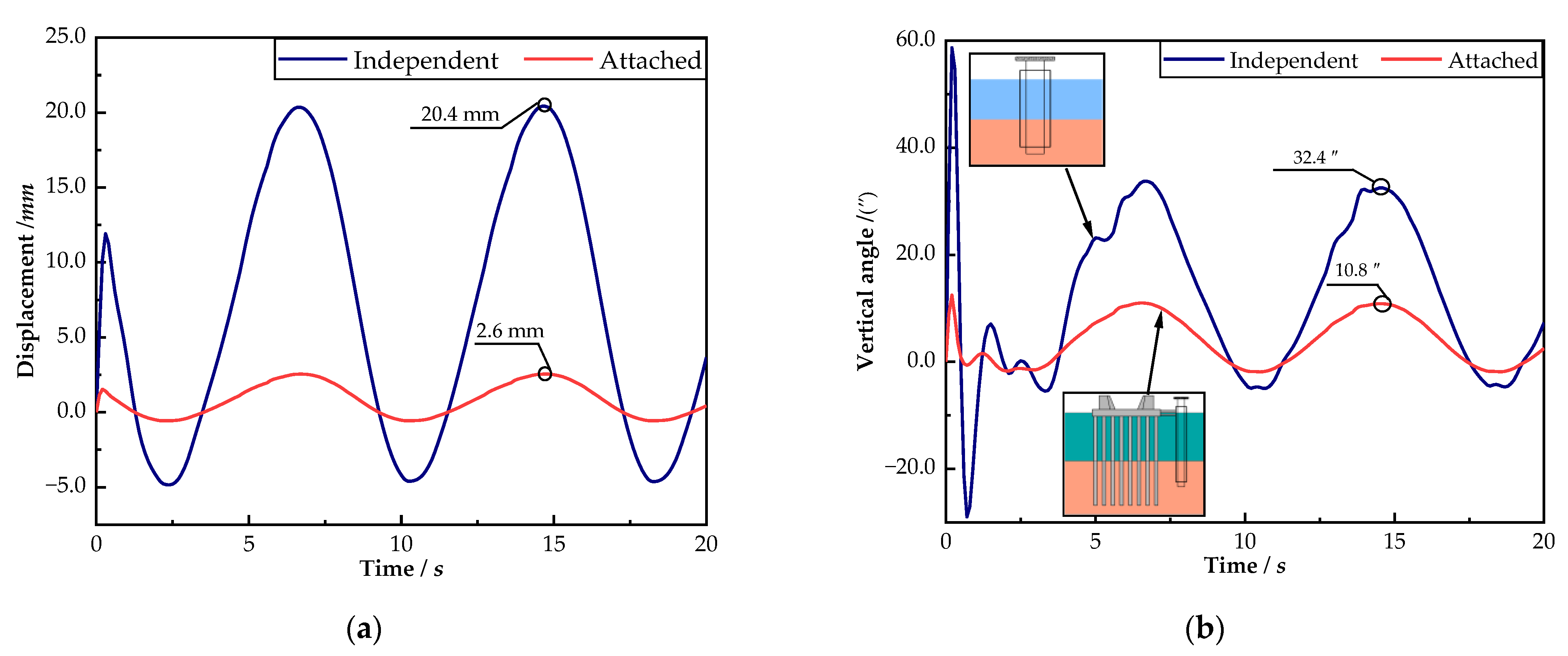
The attached layout scheme proposed in this paper is to attach the external support system of the combined survey platform to the cushion cap with attachments to improve the lateral stiffness of the external support system, reduce the structure size, and ensure the working performance of the survey platform. To verify the working performance of the attached combined survey platform under the influence of the wave-current load, the wave height, the wave period, the water flow speed, and the water depth are set as 1.0 m, 8.0 s, 1.0 m/s, and 20.0 m, respectively. The combined survey platform mentioned in Scheme 5 in Table 4 is respectively arranged in independent and attached layouts. Then, the wave-current load time history loading is carried out. Figure 17a,b show the time history of the displacement of the free end of the external support system and the vertical angle of the platform, respectively, for the single-pile combined survey platform with two types of arrangement. It can be seen from the figure that, under the influence of the wave-current load, the maximum displacement of the external support system of the independently set combined survey platform is 20.4 mm, and the maximum vertical angle of the platform is 32.4”. For the attached combined survey platform, the maximum displacement of the external support system is only 2.6 mm and the maximum vertical angle of the platform is 10.8”.
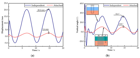
Figure 17.
The time history of the structural response of the combined survey platform with two types of layouts. (a) The displacement of the external support system. (b) The vertical angle of the platform.
The stiffness of the external support system can be increased by attaching the external support system to the cushion cap, and the displacement of the external support system and the vertical angle of the platform can be significantly reduced, which verifies the expected effect of the attached layout scheme proposed in this paper.
3.2.2. The Influence of Sea Conditions
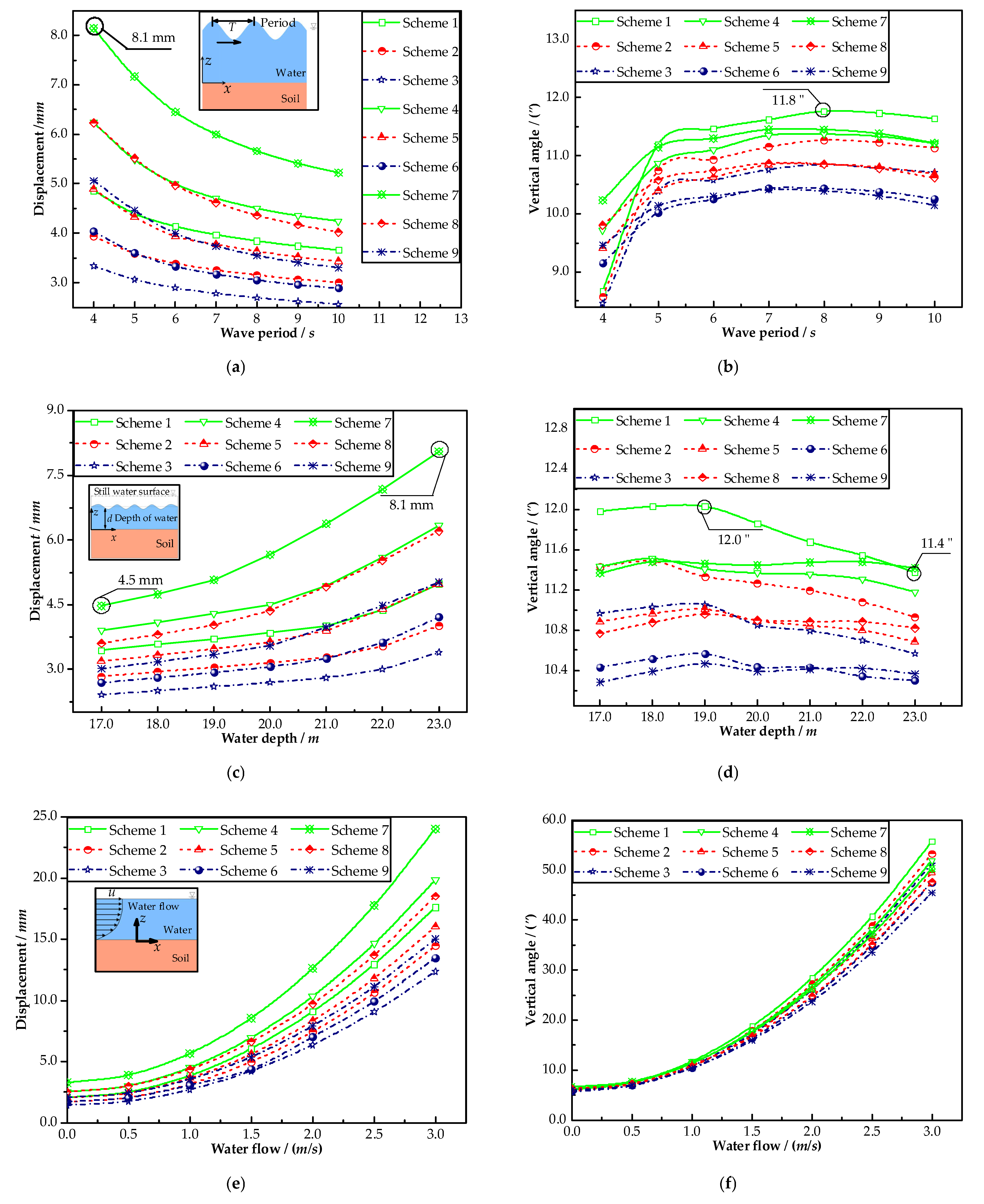
The wave height, the water flow speed, the water depth, and the wave-current period are set as 1.0 m, 1.0 m/s, 20.0 m, and 4.0–10.0 s, respectively. The wave-current load is loaded on the survey platform with different size combination schemes. Figure 18a,b, respectively, show the influence of the maximum displacement of the external support system and the maximum vertical angle of the platform by the wave-current period. As shown in the figure, due to the change in the wave-current period, the displacement of the external support system and the vertical angle of the platform are less affected—the maximum displacement of the external support system is only 8.1 mm, and the maximum vertical angle of the platform is 11.8”. With the period of the wave-current increasing gradually, the maximum displacement of the external support system decreases gradually and then flattens out, while the maximum vertical angle of the platform increases gradually and then flattens out.
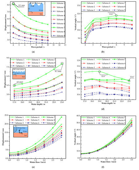
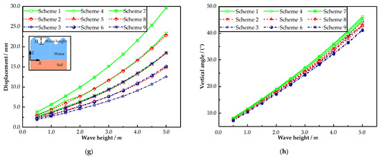
Figure 18.
The most unfavorable effect of sea conditions on the working performance of the attached combined survey platform. (a,c,e,g) The maximum displacement of the external support system. (b,d,f,h) The maximum vertical angle of the platform.
The wave height, the water flow speed, the wave-current period, and the water depth are set as 1.0 m, 1.0 m/s, 8.0 s, and 17.0~23.0 m, respectively. Figure 18c,d, respectively, show the influence of the maximum displacement of the external support system and the maximum vertical angle of the platform by the tide. As shown in the figure, the variation in the water depth caused by the tides has a low impact on the displacement of the external support system and the vertical angle of the attached combined survey platform. The maximum displacement of the external support system gradually increases with the increase in water depth. Within the selected water depth range, the maximum change in the maximum displacement of the external support system is about 3.6 mm. The vertical angle of the platform shows a trend of rising first and then decreasing, and the maximum change in the vertical angle within the selected water depth change range is about 0.6′′.
The wave-current period, the water depth, the wave height, and the water flow speed are set as 8.0 s, 20.0 m, 1.0 m, and 0–3.0 m/s, respectively. Figure 18e,f, respectively, show the influence of the maximum displacement of the external support system and the maximum vertical angle of the platform by the water flow speed. The figure shows that the water flow speed has a significant influence on the performance of the attached combined survey platform. When the water flow speed increases, the maximum displacement of the external support system and the maximum vertical angle of the platform increase significantly. Changing the pile diameter and the wall thickness affects the displacement of the external support system to a certain extent, but the vertical angle of the platform is less affected. Increasing the pile diameter increases the displacement of the external support system, and increasing the wall thickness can reduce the displacement of the external support system, but the displacement of the external support system is generally small.
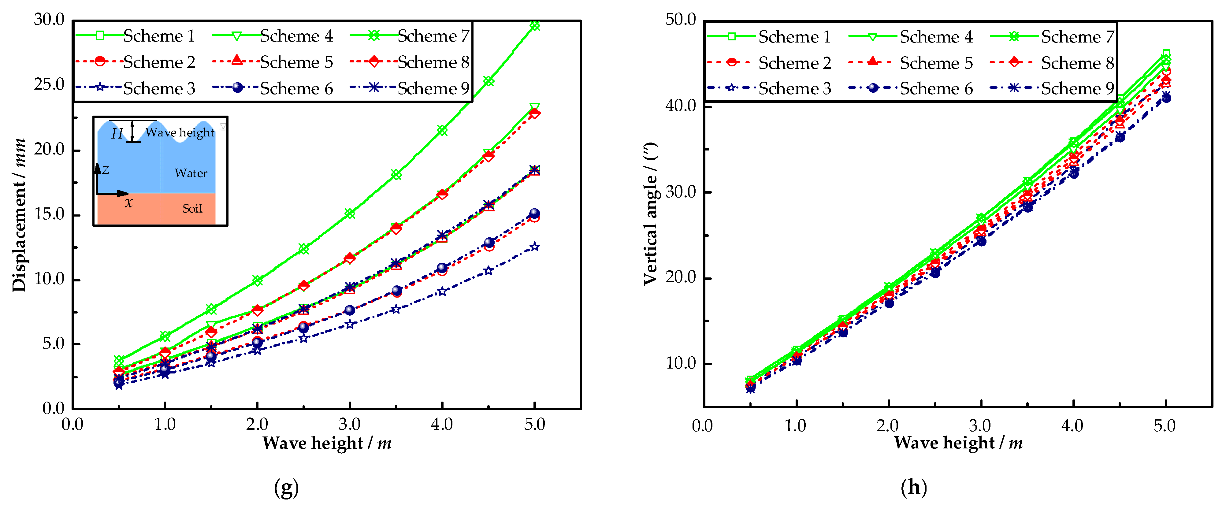
The wave-current period, the water depth, the water flow speed, and the wave height are set as 8.0 s, 20.0 m, 1.0 m/s, and 0.5~5.0 m, respectively. Figure 18g,h, respectively, show the influence of the maximum displacement of the external support system and the maximum vertical angle of the platform by the wave height. As shown in the figure, the maximum displacement of the external support system and the maximum variation of the vertical angle of the platform increase significantly with the increase in wave height. It has great influence on the displacement of the external support system by changing the structural size, but it has little influence on the vertical angle of the platform. With the same wave height, the maximum displacement of the external support system decreases with the increase in the wall thickness and increases with the increase in the pile diameter, and the difference between the different combinations of sizes increases significantly with the increase in the wave height.
4. Discussion
Due to wave-current load, the traditional survey platform has a large shaking amplitude, so it is difficult to meet the high standard requirements of long-distance and high-precision elevation transfer in the construction of sea-crossing bridges. This paper designs a new structure for a combined survey platform based on the basic principle of vibration reduction and isolation to better solve this problem. The internal support system is only subjected to loads transferred by soil and water quality between the internal and external support systems, which has little influence on the displacement of the internal support system and the vertical angle of the platform, so the new structure has excellent working performance.
Two kinds of layout designs are carried out according to the different positions of the survey platform: independent and attached. The wave-current load is loaded on the models of the two layouts. The time history response analysis of the structure shows that: (1) the external support system achieves the expected blocking effect on the wave-current load, significantly reduces the impact of the wave-current load on the internal support system, and provides a guarantee for stable work of the platform on the top of the internal support system; and (2) attaching the external support system to the cushion cap through attachments can increase the stiffness of the external support system, significantly reduce the displacement of the external support, and effectively prevent collision between the internal and external support systems.
Different sea areas have different sea conditions. Through the reasonable setting of sea conditions, the specific effects of the wave-current period, the wave height, the current velocity, and the tide on the two layouts are quantitatively analyzed. The analysis results show that: (1) tide and wave-current periods have little impact on the working performance of the combined survey platform; and (2) the increase in wave height and water flow speed has a significant impact on the working performance of the survey platform.
Through the quantitative analysis of the structural dimensions of the combined survey platforms of the two layouts, it is found that the structural stiffness of the external support system can be improved by increasing the wall thickness and the pile diameter of the external support system, but as the pile diameter increases, the wave-current load on the external support system will also increase. The above analysis shows that: (1) changing the pile diameter and the wall thickness of the external support system has a significant impact on the displacement of the external support system, but it has a small impact on the vertical angle of the platform; (2) the displacement of the external support system of the combined survey platform of the two layouts can be effectively reduced by increasing the wall thickness; and (3) for the independently set combined survey platform, increasing the pile diameter can improve the overall stiffness of the external support system and better reduce the displacement of the external support system. For the attached combined survey platform, increasing the pile diameter can increase the stiffness of the structure, but since the internal and external support systems are single-pile structures and the overall stiffness of the structure is small, the increase in the stiffness caused by the increase in the pile diameter is insufficient to resist the deformation caused by the increase in the wave-current load, and the displacement of the external support system will increase. The above analysis also shows that: (4) for the independent combined survey platform, the pile diameter can be appropriately increased to provide greater rigidity, and the gap between the internal and external support systems is larger to prevent collision between the internal and external support systems; and (5) for the attached combined survey platform, its external support system is attached to the cushion cap through attachments. The displacement of the external support system caused by the wave-current load is small, so the pile diameter and wall thickness of the external support system can be appropriately reduced to ensure the economy of engineering construction.
Different layouts have their characteristics. The structural size of the attached combined survey platform is small, so the construction cost is low. However, its internal support system is a single-pile structure with poor stiffness. It is sensitive to the load transmitted by the water and the soil between the internal and external support systems, and the vertical angle of the platform changes greatly. Moreover, the external support system needs to be attached to the cushion cap, so the construction of the survey platform can only be carried out after the construction of the cushion cap is completed, which limits the construction period. When the longitudinal bridge alignment of the sea-crossing bridge is a curve, the sight of the observation instrument erected on the survey platform is easily blocked, and the field of view is narrow. For the independently set combined survey platform, the wave-current load is borne by the external support system. The displacement of the external support system is large, the gap between the internal and external support systems must be high, and the structural size is large, so the construction cost is high. However, its internal support system is integrated by multiple single piles through lateral connections. It has a large overall stiffness, and the load transmitted by the soil and the water has little impact on the vertical angle of the platform. The position of the survey platform can be reasonably arranged according to the project requirements. Therefore, the field of view of the observation instruments erected on the survey platform is relatively wide.
In sum, the combined survey platform of the two layouts has advantages and disadvantages. In actual engineering, the survey platform of the two layout forms can be reasonably adopted according to the needs.
5. Conclusions
The main research conclusions are as follows:
- Through the comparative analysis of the displacement time-history responses of the internal and external support systems under the influence of the wave-current load, the barrier effect of the external support system on the wave-current load is verified, and the influence of the wave-current load on the internal support system is significantly reduced.
- The external support system of the independently set combined survey platform produces a large displacement. Increasing the pile diameter of the external support system can improve the stiffness of the structure, and the gap between the internal and external support systems can also increase, effectively preventing collision between the internal and external support systems.
- For the independent combined survey platform, when the pile diameters of the internal and external support systems are 0.8 m and 1.2 m and the wall thicknesses are 11.0 mm and 12.0 mm, respectively, the period of the wave is 8.0 s, the water depth is 20.0 m, the speed of water flow is 1.0 m/s, and the wave height is 4.0 m, the maximum variation of the vertical angle of the platform is only 19.3”.
- For the attached combined survey platform, the lateral stiffness of the external support system is increased, and the displacement of the external support system is significantly reduced, because the external support system is connected to the cushion cap through the attachments. When the pile diameters of the internal and external support systems are 2.0 m and 2.4 m, the wall thickness is 14.0 mm and 14.0 mm, and the period of the wave, the water depth, the water flow speed, and the wave height are set as 8.0 s, 20.0 m, 1.0 m/s, and 5.0 m, respectively, the maximum displacement of the outer support system is only 29.6 mm.
6. Patents
There is an invention patent resulting from the work reported in this manuscript. The invention relates to a combined survey platform suitable for strong wave conditions (application number is 202010461340. X).
Author Contributions
Conceptualization, J.X. (Jun Xiao) and J.X. (Jianping Xian); methodology, J.X. (Jun Xiao), J.X. (Jianping Xian) and S.Z.; software, S.Z.; validation, J.X. (Jun Xiao), J.X. (Jianping Xian) and Y.Z.; formal analysis, S.Z.; investigation, J.X. (Jun Xiao), S.L. and Y.Z.; resources, J.X. (Jun Xiao); data curation, S.Z.; writing—original draft preparation, J.X. (Jun Xiao), J.X. (Jianping Xian), S.Z., S.L. and Y.Z.; writing—review and editing, S.Z.; visualization, J.X. (Jun Xiao), J.X. (Jianping Xian) and S.L.; supervision, J.X. (Jun Xiao); project administration, S.Z.; funding acquisition, J.X. (Jun Xiao). All authors have read and agreed to the published version of the manuscript.
Funding
This research was funded by the Science and Technology Project of CCCC (grant number: No. 2020-ZJKJ-QNCX04) and the Science and Technology Special Major Project of CCCC (grant number: No. 2019-ZJKJ-07).
Institutional Review Board Statement
Not applicable.
Informed Consent Statement
Not applicable.
Data Availability Statement
Data are contained within the article.
Conflicts of Interest
The authors declare no conflict of interest.
References
- GB/T 12897-2006; Specifications for the First and Second Order Leveling. Standards Press of China: Beijing, China, 2006.
- Zhu, Y.H.; Xu, T.D. Survey scheme of Hangzhou Bay Sea-crossing Bridge. In Proceedings of the National Conference on Bridge Engineering, China-2005, Ningbo, China, 12–15 October 2015, 1st ed.; China Communication Press: Beijing, China, 2005; pp. 51–58. [Google Scholar]
- Wu, D.J.; Xiong, W.; Zheng, Q. Research on methods and techniques of repetition surveying of the first order control network for Hong Kong-Zhuhai-Macao Bridge. Geotech. Investig. Surv. 2011, 9, 74–78. [Google Scholar]
- Guo, B.J.; Xu, T.D. Leica TCA1800 High-precision ultra-long-distance sea-crossing height leveling. Rail. Investig. Surv. 2007, 1, 1–8. [Google Scholar]
- Wu, D.J.; Xiong, W. A method of sea-crossing trigonometric leveling by total station in the condition of survey station rocking. Bull. Surv. Mapp. 2016, 6, 87–90. [Google Scholar] [CrossRef]
- Xiang, F. Research on a New Method of Control Survey and Construction Survey of Lindingyang Bridge in Shenzhen-Zhongshan Bridge. Master’s Thesis, Southwest Jiaotong University, Sichuan, China, 2021. [Google Scholar]
- Zheng, Q.; Zhao, M.; Xiong, W. Technical research on sea-crossing elevation transference of Huangmaohai Link. Geospatial. Inf. 2019, 4, 178–180,188. [Google Scholar] [CrossRef]
- Xu, Y.; Chen, Y.; Guan, X.; Zhou, J. Approach to Minimizing the Influence of Changeable Observational Environment on Long-Distance Sea-Crossing Trigonometric Leveling. J. Surv. Eng. 2020, 146, 04020018. [Google Scholar] [CrossRef]
- Sang, S.; Xu, X.J. Overview of nonlinear motion response of floating structures. Eng. J. Wuhan Univ. 2010, 43, 608–612. [Google Scholar]
- Wang, Z.P.; Zhou, J.Y.; Chen, G.H.; Dong, B.B.; Huang, R.Z. Data processing and application of super-long-distance cross-sea second-class leveling. Hydro. Surv. Chart. 2021, 41, 40–43,48. [Google Scholar]
- Wang, X.; Zhang, C.; Deng, J.; Su, C.; Gao, Z. Analysis of Factors Influencing Miners’ Unsafe Behaviors in Intelligent Mines using a Novel Hybrid MCDM Model. Int. J. Environ. Res. Public Health 2022, 19, 7368. [Google Scholar] [CrossRef] [PubMed]
- Zienkiewicz, O.C.; Taylor, R.L. The Finite Element Method, Volume 1: The Basis, 5th ed.; Butterworth-Heinemann: Oxford, UK, 2000. [Google Scholar]
- Haroun, M.A. Vibration studies and tests of liquid storage tanks. Earthq. Eng. Struct. Dyn. 1983, 11, 179–206. [Google Scholar] [CrossRef]
- Vatankhah, A.R.; Aghashariatmadari, Z. Improved explicit approximation of liner dispersion relationship for gravity waves: A discussion. Coast. Eng. 2013, 78, 21–22. [Google Scholar] [CrossRef]
- Soulsby, R. Tides, surges and mean sea-level: A handbook for engineers and scientists. Mar. Geol. 1990, 91, 345. [Google Scholar] [CrossRef]
- Hu, Y.; Lei, L.P.; Yang, J.X. Study of wave force on foundation of sea-crossing bridges. J. Waterway. Harbor. 2012, 33, 101–105. [Google Scholar]
- Yao, W.W. An Engineering Approach for Computation of Wave Loads on Pile-Slab Structures. Ph.D. Thesis, Shanghai Jiao Tong University, Shanghai China, 2009. [Google Scholar]
- Fang, C.; Li, Y.L. Analysis of nonlinear wave load on small size substructure of sea-crossing bridge. Rail. Stand. Des. 2017, 61, 100–104. [Google Scholar]
- Techet, A. 13.42 Design Principles for Ocean Vehicles. In MIT Course Lecture Notes; Massachusetts Institute of Technology: Cambridge, MA, USA, 2005. [Google Scholar]
- JST 145-2015; Code of Hydrology for Harbor and Waterway. China Communication Press: Beijing, China, 2005.
- Pan, L.; Zhu, B.; Zhang, J.W.; Kang, A.Z. Dynamic response of pile foundation of cross sea bridge to wave-current load in multiple soil layers. Rail. Stand. Des. 2020, 64, 76–82. [Google Scholar]
- Rawat, A.; Mittal, V.; Chakraborty, T.; Matsagar, V. Earthquake induced sloshing and hydrodynamic pressures in rigid liquid storage tanks analyzed by coupled acoustic-structural and Euler-Lagrange methods. Thin-Walled Struct. 2019, 134, 333–346. [Google Scholar] [CrossRef]
- Systemes, D. Abaqus/Explicit Users’ Manual, Version, 6.14; Dassault Systemes Simulia Corporation: Johnston, RI, USA, 2014. [Google Scholar]
- Qian, D.J.; Miao, X.H.; Wang, X.R. Sound Radiation of Underwater Structure Based on the Arithmetic of Coupled Acoustic-Structural Analysis with ABAQUS. Appl. Mech. Mater. 2012, 226–228, 2249–2252. [Google Scholar] [CrossRef]
- Li, Y.P.; Li, J.B.; Lin, G. Effects of reservoir bottom wave absorption on dynamic response of gravity dams. J. Hydroel. Eng. 2021, 40, 145–154. [Google Scholar] [CrossRef]
- Qiu, Y.X.; Wei, C.H.; Wu, Z.G.; Wang, J.T. Effects of reservoir water on simulations of arch dam dynamic characteristics. J. Hydroel. Eng. 2020, 39, 109–120. [Google Scholar] [CrossRef]
- Huang, Y.M.; Zhao, M.; Wang, P.G.; Cao, Y.H.; Du, X.L. Simplified analysis of water-pile-soil interaction under dynamic loads. J. Vib. Eng. 2021; in press. Available online: https://kns.cnki.net/kcms/detail/32.1349.tb.20210727.1734.008.html(accessed on 27 August 2022).
- Kong, D.S.; Liu, Y.; Deng, M.X.; Hou, D. Analysis of influencing factors of monopile foundation-soil interaction characteristics for offshore wind power. Ocean. Eng. 2021, 39, 100–111. [Google Scholar]
- Dai, S.; Xie, D. An approach for computation of wave load on small dimension pile foundation based on Abaqus. Chin. J. Solid. Mech. 2011, 32, 288–295. [Google Scholar]


Publisher’s Note: MDPI stays neutral with regard to jurisdictional claims in published maps and institutional affiliations. |
© 2022 by the authors. Licensee MDPI, Basel, Switzerland. This article is an open access article distributed under the terms and conditions of the Creative Commons Attribution (CC BY) license (https://creativecommons.org/licenses/by/4.0/).