Article

A Multi-Equipment Task Assignment Model for the Horizontal Stripe Pre-Cut Mining Method

School of Resources and Safety Engineering, Central South University, Changsha 410083, China
*
Author to whom correspondence should be addressed.
Sustainability 2022, 14(24), 16379; https://doi.org/10.3390/su142416379
Submission received: 4 November 2022 / Revised: 2 December 2022 / Accepted: 6 December 2022 / Published: 7 December 2022
(This article belongs to the Special Issue Advances in Intelligent and Sustainable Mining)

Abstract

:
This paper proposes a multi-equipment task assignment model for the horizontal stripe pre-cut mining method to address the problem of cooperative scheduling operation of multi-equipment in underground metal mines under complex constraints. The model is constructed with multiple objectives, including operation time, operational efficiency, equipment utilization rate, and ore grade fluctuation by considering the constraints of time, space, equipment, and processes. The NSGA-III algorithm is used to obtain the solution. The effectiveness of the algorithm is tested based on the actual data from the Chambishi Copper Mine. The results show that the average equipment utilization rate is 51.25%, and the average ore output efficiency is 278.71 tons/hour. The NSGA-III algorithm can quickly generate the optimal multi-equipment task assignment solution. The solution reduces the interference of manual experience and theoretically improves the actual operation of the mine.

1. Introduction

With the rapid development of intelligent mining, underground metal mining equipment has begun to shift toward unmanned operation due to this method’s increased safety and efficiency over manned equipment [1,2]. The artificial intelligence for mining equipment is currently based on unmanned operation of only a single piece of equipment at a time, but mining succession and equipment synergy has yet to improve accordingly [3,4,5]. Therefore, in addition to developing intelligent mining equipment, the question of how to improve the overall production efficiency of underground mines using the collaborative operation of multiple pieces of equipment (multi-equipment) has become one of the urgent problems to be solved in the field of intelligent mine construction.
Underground mining involves a complex production system with various environments and processes that are dynamic, discrete, parallel, and time-bound. The primary goal of intelligent mining equipment scheduling is to coordinate the execution equipment of each process efficiently, reasonably arrange the operation site and operation time of the equipment, realize the parallel operation of multiple-sites and multi-equipment, improve the equipment utilization rate, ensure the close connection of each process, and ensure the operational safety.
In this paper, we analyze the horizontal stripe pre-cut mining method for scheduling, which considers (1) the constraints of inter-stripe, inter-block, inter-slice, and inter-process relationships; (2) uncertain operation and movement times; and (3) the effects of blasting and ventilation, ore output fluctuation, and operational continuity. With the multiple-objectives of total time, stripe average time, process interval, block interval, equipment utilization rate, and ore grade fluctuation, we construct a multi-equipment task assignment model and implement NSGA-III [6,7,8] as the solver. Finally, we demonstrate the intelligent scheduling and efficient operation of multi-equipment under complex collaborative operation conditions and demonstrate that our method greatly improves the overall production efficiency of underground metal mines.
The remainder of this paper is organized as follows: In Section 2, we review the underground mine scheduling research in recent years. In Section 3, we analyze the characteristics and processes of the horizontal stripe pre-cut mining method. In Section 4, we construct the multi-equipment task assignment model, and in Section 5, the case study of Chambishi Copper Mine is conducted and the results are discussed. Section 6 concludes.

2. Literature Review

The research methods for production scheduling optimization of underground mines include linear programming, mixed integer programming (MIP), constraint planning, and simulation, etc. [9,10,11,12,13,14]. This research dates back to the 1970s when Williams et al. [15] used linear programming methods to develop underground mine production plans. Trout et al. [16,17,18,19,20,21] proposed to develop underground mine production plans based on MIP.
Campeau et al. [22] proposed an MIP-based optimization model for the short-term planning of underground mines, and Newman et al. [23] focused on the problem of matching short-term plans with long-term plans. Martinez et al. [24] improved this model by introducing a heuristic algorithm to improve the speed of the solution, and Nehring et al. [25] and Little et al. [26] proposed integrated MIP-based optimization models for short-term and medium-term production planning. More recently, Campeau et al. [27] improved an integrated MIP-based optimization model for underground mines’ short-term and medium-term planning.
Regarding research with simulation, Chanda [28] proposed a production scheduling model that combined MIP and simulation, and Nehring et al. [29] proposed a new production scheduling optimization model based on MIP that significantly reduced the model-solving time. Along similar lines, O’Sullivan et al. [30] constructed a MIP production scheduling model and applied a heuristic decomposition method to solve the model, and Foroughi et al. [31] proposed a comprehensive model for integrated optimal mine distribution and production scheduling based on multi-objective integer programming (MOIP), which they solved using the NSGA algorithm. Finally, Lindh et al. [32] proposed a heuristic method based on logical Benders decomposition (LBBD) to solve a large-scale example of the short-term scheduling problem in underground mines.
They were not the first to take novel solution approaches a step further, however. Tsomondo et al. [33] proposed a scheduling model for underground metal mines that integrated short-term production scheduling and equipment assignment and used a fuzzy logic modeling approach to generate shift schedules. Nehring et al. [34] improved this model and proposed a new MIP-based dynamic short-term production scheduling and equipment assignment model, which they solved using the CPLEX tool. Similarly, Song et al. [35] developed a decision support tool for mobile mining equipment in underground mines, proposed algorithms for sorting, grouping, machine set, and machine sharing to assist miners in rapidly rescheduling trackless equipment, and validated the effectiveness of their algorithm with Kittila mine data.
Li et al. [36] constructed a production succession and dynamic scheduling model and solved it using an improved genetic algorithm to generate the optimal scheduling scheme. Improvements to this model were found by Wang et al. [37] who considered the constraints between processes and operation surfaces, the number of pieces of equipment, efficiency, and movement time to construct an underground trackless equipment scheduling model where they also solved the model using a genetic algorithm. The influence of equipment failure was also considered in order to improve the robustness of the model. Hou et al. [38] similarly proposed a dynamic scheduling optimization model for underground mining equipment based on an improved genetic algorithm by considering the uncertainty of equipment operation time wherein the optimal plan was immediately reworked once an unexpected event occurred.
Modeling the concept of real-world constraints explicitly, Åstrand et al. [39] proposed an underground mine equipment scheduling model based on constraint planning that considered production interruptions and delays and generated a scheduling scheme based on actual mine data. Then, they [40] extended the model to consider the effect of equipment movement time and proposed a constraint planning-based fixed-neighborhood-size simple neighborhood search strategy for the short-term scheduling of underground mines. Subsequently, they [41] improved on this and proposed a dynamically adjusted neighborhood size large neighborhood search strategy based on constraint planning for short-term underground mine operation scheduling. Finally, Hammami et al. [42] investigated the underground mine mobile equipment scheduling problem with random operation times for mining equipment.
In summary, much previous research has been conducted on underground mine scheduling. However, the consideration of mining process and spatial constraints in the existing research is still fixed and protocolized. Its application effect will thus be reduced in the face of complex spatial constraints, multi-processes, backfilling, and other real-world conditions. This paper focuses on the horizontal stripe pre-cut mining method based on previous research in order to build a multi-equipment task assignment model. Some complex conditions are considered, such as multiple-slice spatial constraints, complex combined processes, and equipment clustering operations, etc.

3. Analysis of the Horizontal Stripe Pre-Cut Mining Method

3.1. Mining Method Process Analysis

Underground mining is a production activity that consists of discrete or continuous operational processes that crush ore to a suitable size and transport it to the surface. Ore recovery is the most important and complex part of the process and is characterized by a harsh operation environment, complex process links, discrete operation sites, multi-equipment, and complex spatio-temporal restrictions. Therefore, the equipment task assignment under different mining methods is necessarily different.
The horizontal stripe pre-cut mining method is designed for underground metal mines with horizontal orebodies. This method divides the orebody into multiple areas at certain intervals along extending and dip directions. Each area is then divided into multi-stripes by fixed width. The stripes within an area are mined in adjacent groupings of three or more, and the void zone is backfilled to maintain the mechanical stability in the underground. Since these are independent mining units, the stripes are divided into blocks according to a fixed length. As shown in Figure 1, the green color indicates the first-step stripes, while the blue stripes can be further mined only after the completion of backfilling in the first-step stripes.
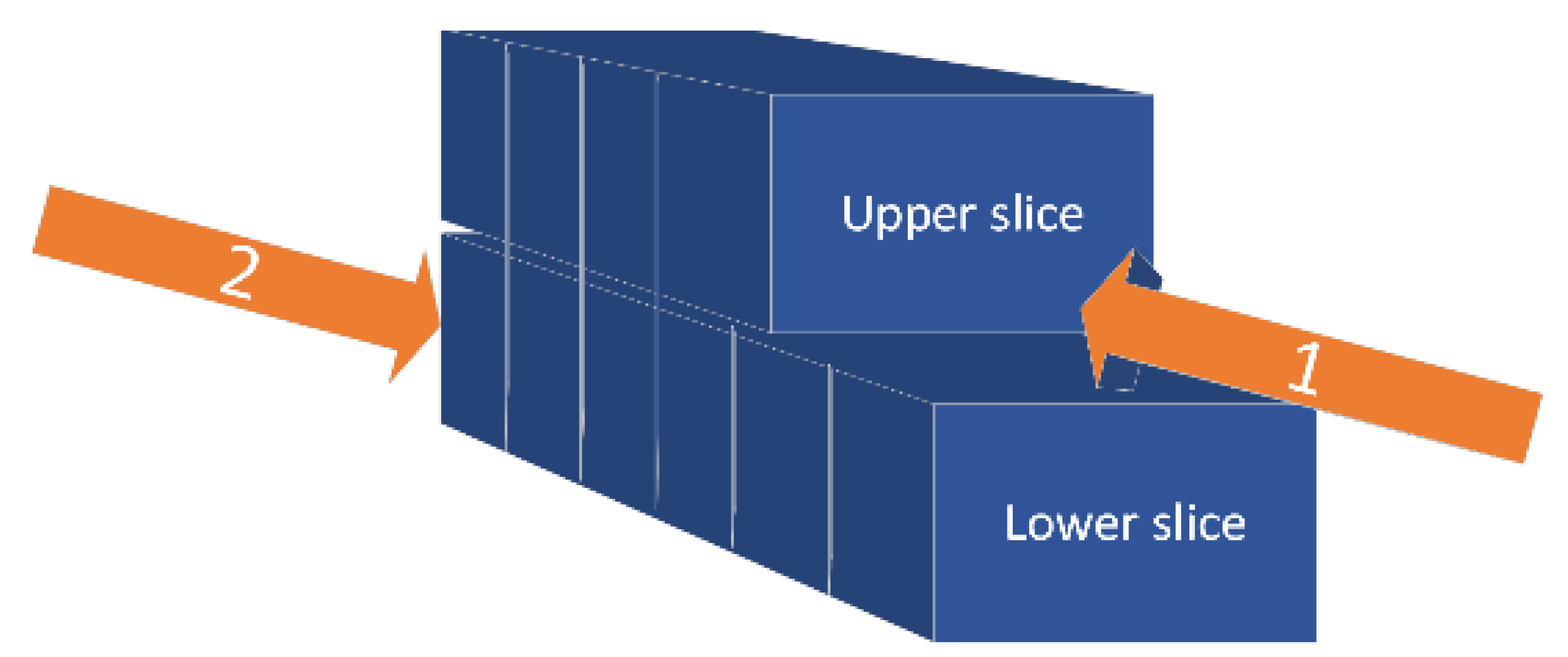
Each block can be divided into an upper slice and a lower slice. The upper slice is designed to create space for further blasting and is drilled horizontally, which requires scaling and anchor support for the exposed rock. The lower slice is designed to mass-produce ore with vertical deep drilling. There is a binding constraint between the upper and lower slices within the same stripe; the completion of the upper slice in all blocks is required before the start of any lower slice. As shown in Figure 2, the upper slice is mined forward while the lower slice is mined backward, completing the entire stripe block by block.
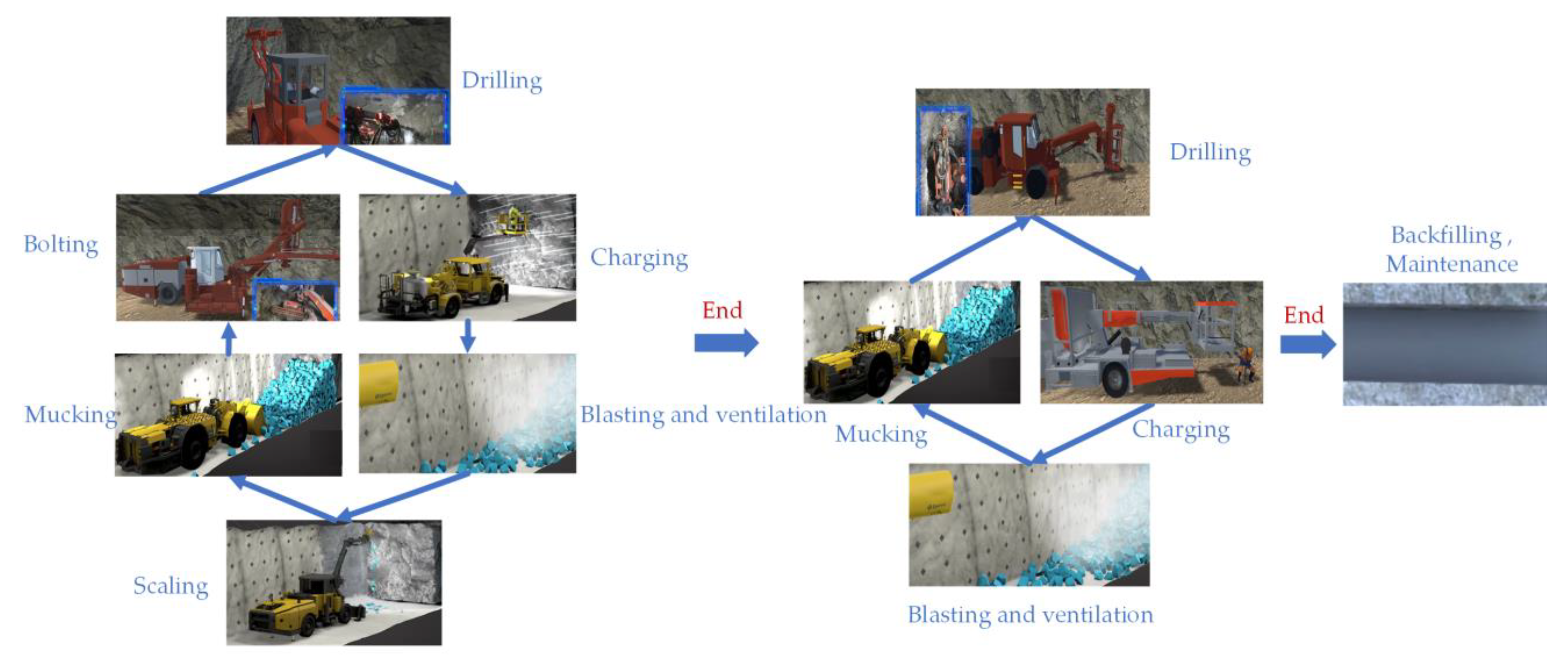
As the smallest mining units, the upper and lower slices of a block require a series of processes to crush the orebody to a reasonable size and haul it. These processes include drilling, charging, blasting and ventilation, scaling, mucking, bolting, backfilling, and maintenance. The drilling process uses drilling jumbos to drill holes in the orebody for filling with explosives. A horizontal drilling jumbo is used for the upper slice, and a downward drilling jumbo is used for the lower slice. The charging process uses a charging dolly to fill the holes with explosives and to lay detonator fuses and other facilities, and the blasting process is operated by professional blasting personnel. To ensure safety, the operation is usually carried out during a fixed time, and as extraneous operations are interrupted and suspended as extraneous personnel are withdrawn from the faces. Due to the dust and toxic gases that are present after blasting, ventilation is required for a certain period of time, and the ventilation time is related to the amount of explosives used. In addition, the destruction of the orebody caused by blasting usually leaves some unstable rocks on the surface of the stopes that can easily collapse and endanger the personnel.
The scaling process exists to clear the loose rock from the surface using scaling jumbos to ensure the safety of subsequent operations, and the mucking process is necessary in order to load the ore by LHD (Load-Haul-Dump) and haul it to the nearest ore pass. The LHD circulates between the stope and the ore pass until all the ore is delivered. Next, the bolting process installs anchors at the top of the stope so that the goaf can remain stable for a longer period, which provides a safe space for the subsequent block operations. Bolting only ensures the short-term stability of the goaf; backfilling fills the goaf with slurry to bring it into a stable state. This ensures the long-term stability of the rock mechanics while providing the necessary conditions for mining in the surrounding area. Each stripe is usually filled uniformly after the blocks within the stripe are completed, including backfilling and maintenance. Backfilling requires the preparation of a pipeline in order to move the slurry, and this is related to the stripe volume and filling capacity. The maintenance time is usually a fixed value, mainly determined by the solidification of the slurry, and is related to the slurry composition.
The process for the upper slice includes drilling, charging, blasting and ventilation, scaling, mucking, and bolting, and that of the lower slice includes drilling, charging, blasting and ventilation, and mucking. Each stripe includes multi-blocks with the upper and lower slices that are uniformly backfilled and maintained after all recovery. The overall process cycle is shown in Figure 3. Figure 3 integrates the process for the upper and lower slices. The left side of Figure 3 represents the process for the upper slice, and the middle of Figure 3 represents the process for the upper slice. After the upper and lower slices have been completed, backfilling and maintenance will be carried out, as shown on the right side of Figure 3.

3.2. Multi-Equipment Task Assignment Definition

The horizontal stripe pre-cut mining method has complex constraints for areas, stripes, blocks, and slices. The operation sites are discrete, and specific processes require specific mining equipment. Therefore, the multi-equipment task assignment problem for the horizontal stripe pre-cut mining can be transformed into a “multi-sites, multi-processes, multi-equipment” arrangement problem. This problem is essentially a flow shop scheduling problem. However, considerations for specific mining characteristics need to be incorporated to enable the flow shop modeling, detailed below.
Inter-stripe constraint: The stripes within an area are mined in adjacent groups of three or more, and the void zone is backfilled to maintain the mechanical stability under the ground. These stripes should be in an “unmined” or “backfilled and maintained” state before the start of the target stripe.
Inter-block constraint: The upper slice is mined forward, but the lower slice is mined backward, completing the entire stripe block by block. Only when all operations of the previous block are completed can the next block be started.
Inter-slice constraint: Completing the upper slice in all blocks is required before the start of any lower slice.
Inter-process constraint: Each mining unit requires the completion of several different processes, and the sequence of processes within each mining unit is not interchangeable.
Impact of equipment movement: Since the underground stopes are connected by narrow tunnels, the same equipment serving different mining units must take movement time into account, especially the movement of equipment between areas, which takes the most time.
Effects of blasting and ventilation: Blasting and ventilation affect other operations in the surrounding zone. When blasting and ventilation occur in the same area, other operations need to be interrupted and suspended. To improve the regularity of this process, mines stipulate that the operation occurs at the moment of shift changeover (for example, starting at 0:00, 8:00, and 16:00 each day).
The impact of ore output fluctuations: The purpose of mining is to produce ore. Since metal ore has different grades, it is important to both ensure stable ore output per shift and maintain stable ore grade.
Impact of operational continuity: To avoid the risk of rock mechanical instability due to long exposure time in the stope, operational continuity needs to be maximized. The process interval time within the same block should be kept as short as possible, and the block interval time within the same stripe should also be kept as short as possible.
Therefore, the multi-equipment task assignment problem for the horizontal stripe pre-cut mining method is described as follows: there are several areas, several stripes within each area, and several blocks within the stripes. Each block is divided into an upper slice and a lower slice that can together be deemed as an independent mining unit. Each mining unit needs to go through several nontransferable processes. Each process corresponds to several pieces of specific equipment, and this equipment can only work in one block simultaneously. There are different ore volumes, grades, and other parameters. After all mining units within the same stripe have been completed, they must be backfilled and maintained. The core of this problem is when to assign certain equipment to certain mining units to perform certain processes to achieve the expected production results.

4. Modeling and Solution Methodology

We now abstract the multi-equipment task assignment problem for the horizontal stripe pre-cut mining method into a mathematical model and solve it using the NSGA-III algorithm.

4.1. Notations

Table 1, Table 2 and Table 3 respectively show the indices and sets, parameters, and variables of the model.

4.2. Mathematical Model

4.2.1. Objective Functions

(1) Minimum total time
min maxTE ikm minTS iknm
(2) Minimum stripe average time
min i = 1 I k = 1 K TE ikm i = 1 I k = 1 K ik , m = 8
(3) Minimum process interval
min i = 1 I k = 1 K ( n = 1 N m = 1 5 DT ikn , m , m + 1 + n = N + 1 E m = 1 2 DT ikn , m , m + 1 + n = N + 1 E m = 3 3 DT ikn , m , m + 2 )
(4) Minimum block interval
min i = 1 I k = 1 K ( n = 1 N ( m = 1 1 TS ik , n + 1 , m m = 6 6 TE ik , n , m + n = N + 1 E ( m = 1 1 TS ik , n + 1 , m m = 5 5 TE ik , n , m ) )
(5) Maximize equipment utilization rate
max i = 1 I k = 1 K n = 1 E ( TE iknm TS iknm Bl siknm × T ven , ikn + i = 1 I TM i , i + 1 + k = 1 K TM ik , k ) maxTE iknm minTS iknm i = 1 I k = 1 K Bl siknm × T ven , ikn , m 3 , 7 , 8
(6) Minimum ore grade fluctuation
The formula for the ore grade during a certain shift is as follows:
G t 1 t 2 = i = 1 I k = 1 K n = 1 E ( T t 1 t 2 / T y , ikn ) × Q ikn × G ikn i = 1 I k = 1 K n = 1 E ( T t 1 t 2 / T y , ikn ) × Q ikn
Note: T t 1 t 2 means the time of ore output during a certain shift
The formula for the ore grade during the total time is as follows:
G = i = 1 I k = 1 K n = 1 E Q ikn × G ikn i = 1 I k = 1 K n = 1 E Q ikn
The formula for shifts is as follows:
s = maxTE ikm minTS iknm 8
Ore grade fluctuation is expressed by variance, and the formula for the minimum ore grade fluctuation is as follows:
min ( s = 1 s ( G t 1 t 2 G ) 2 s )

4.2.2. Equivalent Relations

Equivalent Relation 1: The total length of the blasting hole is related to the ore volume and avalanche ore volume per meter.
L pao , ikn = Q ikn q ikn
Equivalent Relation 2: The operation time of a horizontal drilling jumbo, downward drilling jumbo, and charging dolly is related to the total length of the blasting holes and the operational efficiency.
T h , ikn = L pao , ikn P h = Q ikn q ikn × P h , n 1 , N
T r , ikn = L pao , ikn P r = Q ikn q ikn × P r , n N + 1 , E  
T u , ikn = L pao , ikn P u = Q ikn q ikn × P u
Equivalent Relation 3: The blasting and ventilation time is positively correlated with the total length of the blasting holes and the constant factor β.
T ven , ikn = β × L pao , ikn = β × Q ikn q ikn
Equivalent Relation 4: The LHD operation time is related to the ore volume, distance factor, operational efficiency discount factor, and ideal operational efficiency.
T y , ikn = Q ikn × φ ikn ρ ikny × P y
Equivalent Relation 5: The operation time of the bolting jumbo is related to the volume and height of the block, the number of anchors per square meter, and the operational efficiency.
T w , ikn = V ikn × N ikn H ik × P w
Equivalent Relation 6: The backfilling time of the filling pipeline is related to the total volume of blocks and the filling capacity.
T v , ik = 1 E V ikn / P v
Equivalent Relation 7: The process interval is the interval time between the ending time of jm and the starting time of jm+1.
DT ikn , m , m + 1 = TS iknm + 1 TE iknm
Equivalent Relation 8: Any equipment movement time is related to distance and walking speed.
TM i , i + 1 = D i i + 1 Vel
TM ik , k = D i , k i , k Vel

4.2.3. Constraints

Constraint 1: Mining sequence constraint, there is a sequential order of mining blocks.
TS ikn + 11 TE ikn 6 , n 1 , N
TS ikn + 11 TE ikn 5 , n N + 1 , E
Constraint 2: Process constraint, there is a sequence between processes.
TS iknm + 1 TE iknm
Constraint 3: All other processes are suspended until the blasting and ventilation have been completed.
TE iknm = TS iknm + T work + Bl siknm × T ven , ikn , m 3
Constraint 4: The starting time of other processes lags behind the ending time of blasting and ventilation for the current operation cycle, and does not exceed the starting time of blasting and ventilation for the next operation cycle.
TE ikn , 3 TS iknm TS ikn + 1 , 3 , m 3
Constraint 5: The equipment movement constraint includes the movement constraint between adjacent areas and the movement constraint between stripes within an area.
TS i + 1 knm TE iknm + TM i , i + 1
TS iknm TE ik nm + TM ik , k
Constraint 6: Stripe constraint, the stripes within an area are mined in adjacent groups of three or more.
TS iknm TE ik ± 3 nm TE iknm TS ik ± 3 nm
TS ikm TE ik ± 3 m TE ikm TS ik ± 3 m
TS iknm TE ik ± 2 nm TE iknm TS ik ± 2 nm
TS ikm TE ik ± 2 m TE ikm TS ik ± 2 m
TS iknm TE ik ± 1 nm TE iknm TS ik ± 1 nm
TS ikm TE ik ± 1 m TE ikm TS ik ± 1 m
Constraint 7: Ore grade constraint, there are an upper and lower bound for the ore grade during the total time.
G G G +

4.3. Solution Method

The proposed model includes six objectives and seven constraints, some of which are nonlinear. Some constraints are also related to time deduction, such as blasting and ventilation windows, which make the problem difficult to solve directly by conventional mathematical programming methods. In this paper, we therefore use the simulation of the mining process based on the time-step method to derive the operational effect of the solution, and the optimization of the solution is carried out by a heuristic algorithm.
The mining process simulation is based on the time-step method. Starting from the system initialization at time 0, the system state is judged at every time t. According to the constraint relationship, the operational process is executed, and the operation state of the operation units and equipment is changed until all the operation units complete the operation.
The optimization of the multi-equipment task assignment solution is then performed iteratively using a genetic algorithm that gradually converges to the optimal solution. The NSGA-III algorithm, which is more suitable for high-dimensional objective optimization, was chosen because of the high objective dimensionality of the model (six objectives). Since the multi-equipment task assignment problem for mining operations has been transformed into a flow shop scheduling problem, we chose to implement it when the MSOS coding method is chosen [43].

5. Case Study

5.1. Datasets

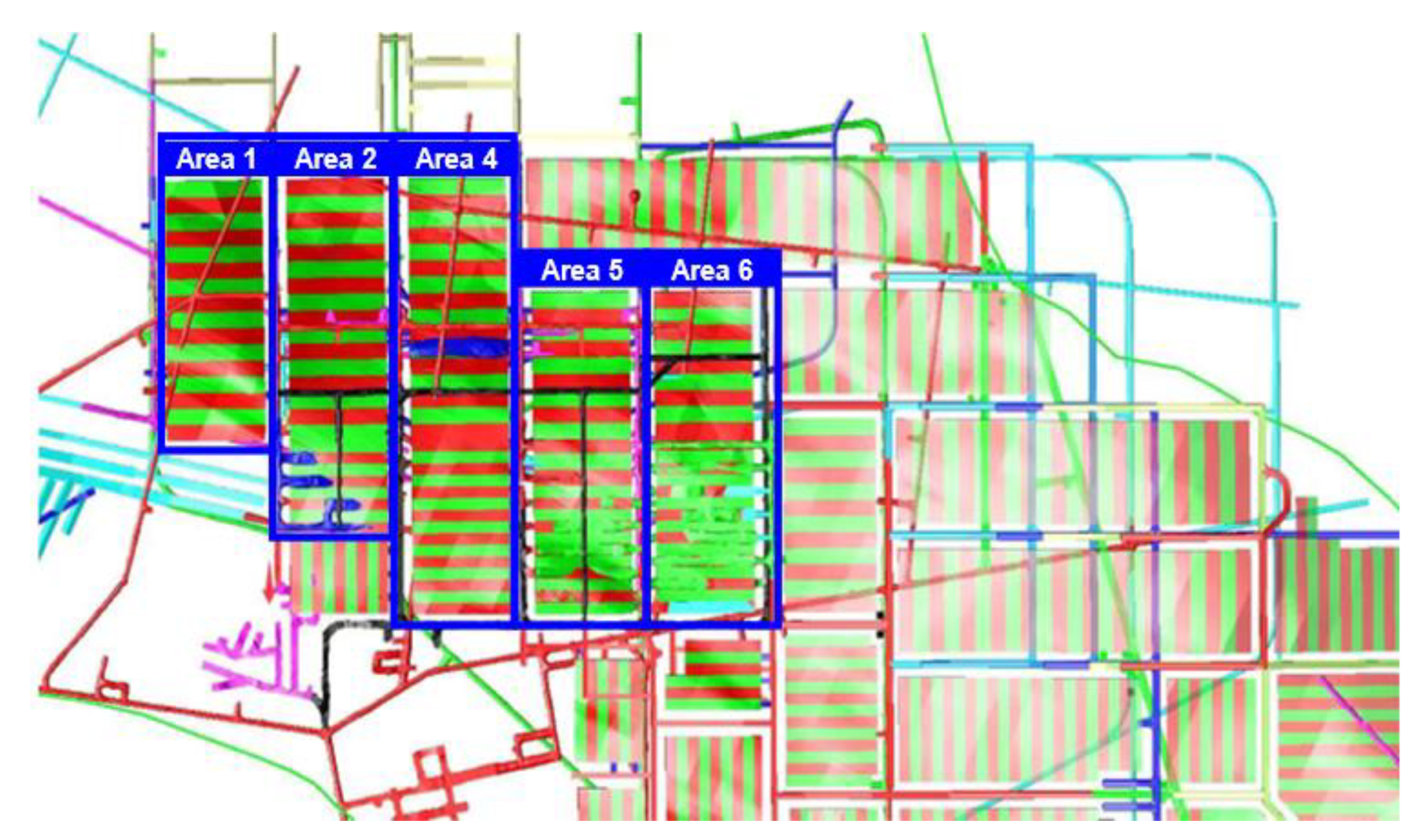
The Chambishi Copper Mine of the China Africa Mining Co., Ltd. is located in the Copper Belt Province of the Republic of Zambia in south-central Africa. The mine has three mining areas. For this paper, we take the southeast mining area as a case study. The southeast mining area is located about 7 km southeast of the main mining area and has a large burial depth, ranging from 469.15 m to 1242.58 m. The boundary of this optimization is shown in Figure 4.
The zone consists of five areas, namely NO.1, NO.2, NO.4, NO.5, and NO.6, which are connected by flat tunnels and ramp roads. The areas are divided into stripes along the inclination with a width of 12.5 m, and each stripe is divided into multiple blocks along the strike with a length of 5 m. The blocks are divided into the upper and lower slices with an upper slice height of 4 m for pre-cutting and a lower slice height that varies with the thickness of the orebody. The main parameters of the stope are shown in Table 4.
A Sandvik DD422I jumbo is used for the upper slice, and a Sandvik DL421 is used for the lower slice. The emulsion explosive is loaded by charging dolly, and blasting operations are uniformly started at 0:00, 08:00, and 16:00 each day, with ventilation timed according to the charging volume. During the blasts, other operations are suspended in the area. A scaling jumbo is used for scaling, and a Sandvik AutoLH514 LHD is used to load and unload ore in multiple cycles between the stope and the ore pass. A D3411 machine with plus pipe slit anchors is used for bolting, and paste-filling technology is used for backfilling from the surface backfilling station to the stripe void zone via pipelines. After the backfilling is completed, it is left to rest for 28 days for maintenance. The main technical parameters of the mining equipment are shown in Table 5.

5.2. Result

To find solve the constrained optimization of the model, the parameters and equipment were as follows. The population of the NSGA III was 800, the evolutionary generation was 400, and the computing platform was an Intel(R) Core(TM) i7-8550U CPU, with 16GB RAM, running Python 3.7 @ Anaconda 3. We took each single objective optimization for comparison. The results are shown in Table 6.
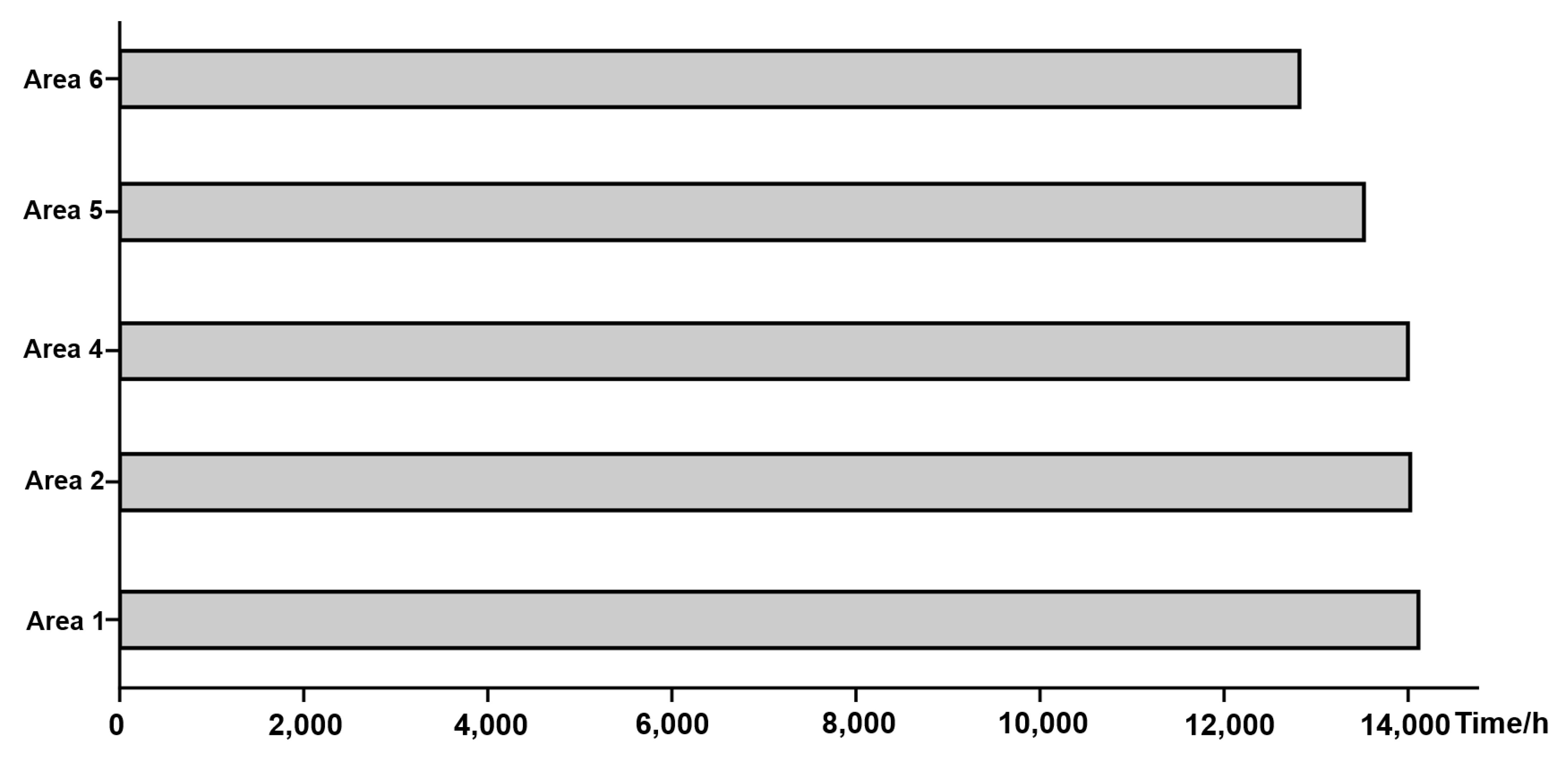
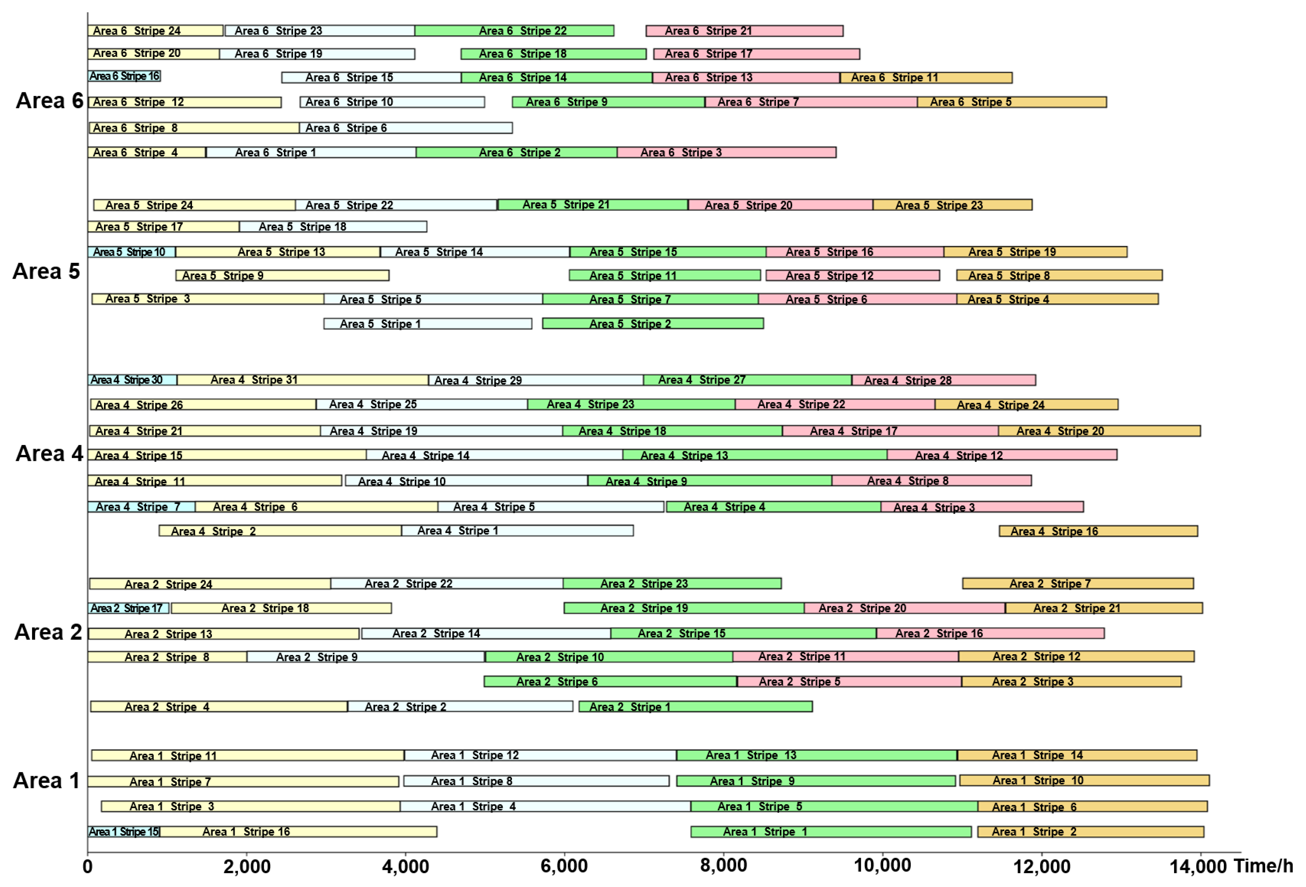
Specifically, we found that the overall completion time of operational progress would be 587.67 d, and the average time for completing each area would be 570.30 d, with Area 1 taking the longest time. The Gantt chart for each area is shown in Figure 5.
The average completion time for each stripe would be 111.15 d. The Gantt chart of operational progress and the continuity of the stripes are shown in Figure 6. From the figure, we can see that the stripes are mined in groups of three or more that are adjacent to each other, and multiple stripes are operating simultaneously in each area.
We also performed further analysis of the block-to-process continuity within the stripe performed. Due to a large amount of data, the Gantt chart is drawn for the first 3000 h of the Area 1 only, as an example, in Figure 7. Here, we can see the inter-process continuity, inter-block continuity, and continuity of the upper and lower slices within the stripe. The average interval time in each stripe is 28.91 d, accounting for 26.01% of the average completion time of the stripe, which ensures a good succession of mining operations.
We also further analyzed the equipment utilization rate statistically, as shown in Table 7. The individual equipment is also taken as the vertical axis to draw the Gantt chart for equipment operational succession in Figure 8. Due to the problem of data volume, only a partial diagram is presented. The 3000–5000 h working life of some jumbos was selected as an example for the figure. The figure shows the operation time and movement time of different equipment, where the white part indicates that the equipment is idle. During this period, equipment maintenance and fuel replenishment can be carried out.
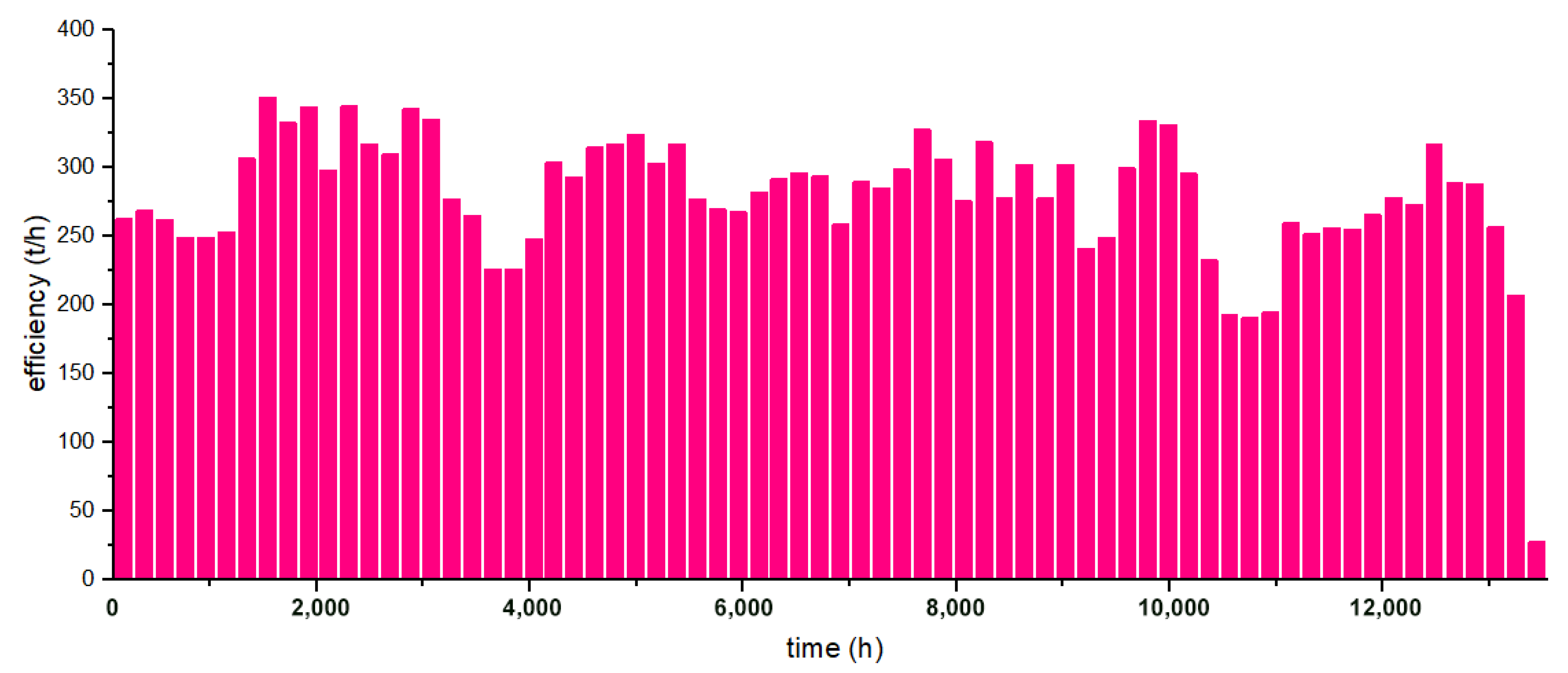
Statistical analysis was likewise conducted on the ore output for each time interval to obtain ore output fluctuation, as shown in Figure 9. The average ore output efficiency was 278.71 tons/hour, and the dispersion coefficient of the ore output efficiency fluctuation was 0.33, which is considered a low level.
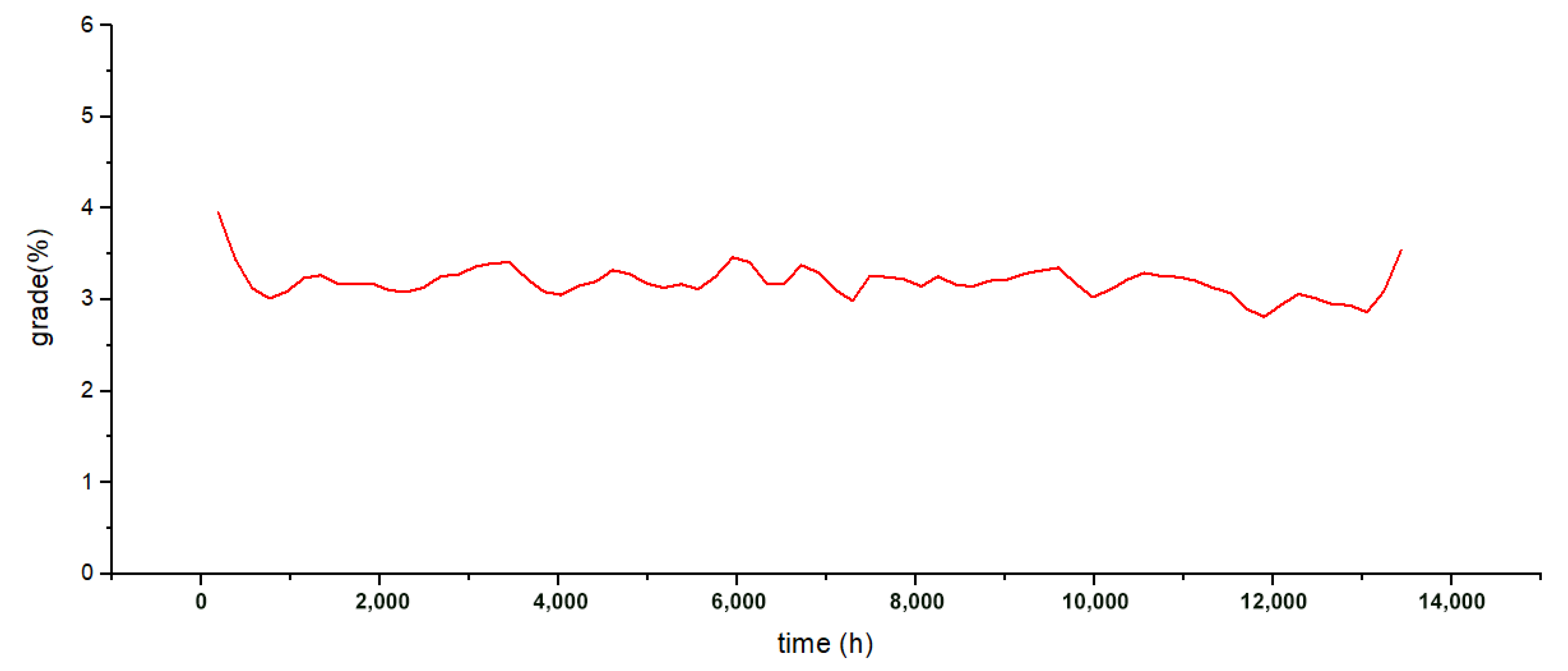
Finally, we statistical analyzed the ore output grade to obtain ore grade fluctuation, as shown in Figure 10. The average ore grade was 3.19%, and the dispersion coefficient of grade fluctuation was 0.06, which is considered to be a good level that can supply a consistent grade for the concentrator.

5.3. Discussion

In this paper, we built a multi-equipment task assignment model for operation duration, operational efficiency, equipment utilization rate, and grade fluctuation in order to address the multi-equipment task assignment problem for the horizontal stripe pre-cut mining method. Mines usually assign specific equipment to designated areas for cyclic operation until all tasks are completed prior to changing areas. Although this approach is convenient for mine management, with the massive investment in intelligent, unmanned equipment, multi-equipment needs to be suitable for more flexible assigning. Recent papers have recognized this and conducted studies to optimize the combination of multiple areas and multi-equipment. However, the consideration of the mining process and spatial constraints in the existing research is fixed and protocolized, and its applicability is reduced in the face of complex spatial constraints, multiple processes, backfilling, and other conditions that are common in underground metal mines.
This paper makes improvements to the existing literature for these specific mining conditions. By considering the constraints of time, space, equipment, and processes, the operability of the solution is ensured, and conflicts during the execution process that often occur during manual preparation are completely avoided. Through multiple-objective programming, the six most important objectives were selected for integrated optimization, which means that the results not only take into account ore volume, grade fluctuations, and equipment utilization but also ensure operational efficiency, and achievement of comprehensive optimization decisions in multiple objective dimensions. The case study at the Chambishi Copper Mine shows the effectiveness and reliability of our algorithm. We presented the optimization results in Gantt charts with multiple dimensions so as to guide the actual production process visually and effectively. The optimal assigning solution was obtained by computer optimization, and improved production results to a certain extent, reduced the interference of manual experience, and made the solution more consistent with the actual operational process.
However, some limitations of the optimization model must be acknowledged. To ensure a high succession of stripes, blocks, and processes, the equipment utilization rate is sacrificed to some extent in the optimal solution. In the future, the number of various types of equipment can be adjusted, and the priority relationship between multiple objectives can be adjusted to make the optimization results more ideal from a utilization standpoint. In addition, the operating environment of an underground metal mine is complex and harsh, and it is easy to experience emergencies, such as equipment failure, roof collapse, and ore pass blockage. Future improvements can be made by making the tasks dynamic, which is more in line with actual production.

6. Conclusions

We proposed a multi-equipment task assignment model for the horizontal stripe pre-cut mining method in order to solve the problem of collaborative scheduling operations for multi-equipment under complex time-space constraints. By considering the constraints of time, space, equipment, and processes, the conflict problem in the operational process was solved in a way that is more in line with real world mining operations compared to the existing literature. Moreover, multiple objectives, such as operation time, operational efficiency, equipment utilization rate, and ore grade fluctuation, were selected for integrated optimization, which solves the problem of integrated decision-making when facing multiple conflicting objectives. Most importantly, optimization experiments on actual mine data demonstrated the effectiveness of our algorithm. However, the model constructed in this paper still has limitations, as discussed above. We therefore intend to focus our future research efforts on the following aspects: (1) optimally adjusting the priority relationship between multiple objectives to improve the equipment utilization rate; and (2) considering emergency situations such as equipment failure, roof collapse, and ore pass blockage to improve the dynamics of operational tasks.

Author Contributions

S.T. participated in data analysis, participated in the design of the study and drafted the manuscript, carried out the statistical analyses; S.F. and S.H. collected field data; L.W. and M.J. conceived of the study, designed the study, coordinated the study and helped draft the manuscript. All authors have read and agreed to the published version of the manuscript.

Funding

This work was supported by the National Key Research and Development Program of China (2019YFC0605300, 2022YFC2904105), and the Fundamental Research Funds for the Central Universities of Central South University (2021zzts0284).

Institutional Review Board Statement

Not applicable.

Informed Consent Statement

Not applicable.

Data Availability Statement

Not applicable.

Acknowledgments

We thank the reviewers for their comments and suggestions to improve the quality of the paper.

Conflicts of Interest

The authors declare no conflict of interest.

References

  1. Li, J.; Zhan, K. Intelligent Mining Technology for an Underground Metal Mine Based on Unmanned Equipment. Engineering 2018, 4, 381–391. [Google Scholar] [CrossRef]
  2. Guo, Q.; Cai, M.; Wu, X.; Xi, X.; Ma, M.; Zhang, J. Technological strategies for intelligent mining subject to multifield couplings in deep metal mines toward 2035. Chin. J. Eng. 2022, 44, 476–486. [Google Scholar]
  3. Yu, H.; Zhao, C.; Li, S.; Wang, Z.; Zhang, Y. Pre-Work for the Birth of Driver-Less Scraper (LHD) in the Underground Mine: The Path Tracking Control Based on an LQR Controller and Algorithms Comparison. Sensors 2021, 21, 7839. [Google Scholar] [CrossRef]
  4. Xiao, W.; Liu, M.; Chen, X. Research Status and Development Trend of Underground Intelligent Load-Haul-Dump Vehicle—A Comprehensive Review. Appl. Sci. 2022, 12, 9290. [Google Scholar] [CrossRef]
  5. Zhang, T.; Fu, T.; Cui, Y.; Song, X. Toward Autonomous Mining: Design and Development of an Unmanned Electric Shovel via Point Cloud-Based Optimal Trajectory Planning. Front. Mech. Eng. 2022, 17, 30. [Google Scholar] [CrossRef]
  6. Wang, Y.; van Stein, B.; Back, T.; Emmerich, M. A Tailored NSGA-III for Multi-Objective Flexible Job Shop Scheduling. In Proceedings of the 2020 IEEE Symposium Series on Computational Intelligence (SSCI), Canberra, Australia, 1–4 December 2020; IEEE: New York, NY, USA, 2020; pp. 2746–2753. [Google Scholar]
  7. Sang, Y.; Tan, J.; Liu, W. Research on Many-Objective Flexible Job Shop Intelligent Scheduling Problem Based on Improved NSGA-III. IEEE Access 2020, 8, 157676–157690. [Google Scholar] [CrossRef]
  8. Sun, X.; Wang, Y.; Kang, H.; Shen, Y.; Chen, Q.; Wang, D. Modified Multi-Crossover Operator NSGA-III for Solving Low Carbon Flexible Job Shop Scheduling Problem. Processes 2021, 9, 62. [Google Scholar] [CrossRef]
  9. Ioan, D.; Prodan, I.; Olaru, S.; Stoican, F.; Niculescu, S.-I. Mixed-Integer Programming in Motion Planning. Annu. Rev. Control 2021, 51, 65–87. [Google Scholar] [CrossRef]
  10. Nguyen, T.-D.; Nguyen-Quang, T.; Venkatadri, U.; Diallo, C.; Adams, M. Mathematical Programming Models for Fresh Fruit Supply Chain Optimization: A Review of the Literature and Emerging Trends. AgriEngineering 2021, 3, 519–541. [Google Scholar] [CrossRef]
  11. Yin, T.; Zhang, Z.; Zhang, Y.; Wu, T.; Liang, W. Mixed-Integer Programming Model and Hybrid Driving Algorithm for Multi-Product Partial Disassembly Line Balancing Problem with Multi-Robot Workstations. Robot. Comput.-Integr. Manuf. 2022, 73, 102251. [Google Scholar] [CrossRef]
  12. Zhao, Y.; Zhang, C.; Wang, Y.; Lin, H. Shear-Related Roughness Classification and Strength Model of Natural Rock Joint Based on Fuzzy Comprehensive Evaluation. Int. J. Rock Mech. Min. Sci. 2021, 137, 104550. [Google Scholar] [CrossRef]
  13. Zhao, Y.; Liu, Q.; Zhang, C.; Liao, J.; Lin, H.; Wang, Y. Coupled Seepage-Damage Effect in Fractured Rock Masses: Model Development and a Case Study. Int. J. Rock Mech. Min. Sci. 2021, 144, 104822. [Google Scholar] [CrossRef]
  14. Liu, J.; Zhao, Y.; Tan, T.; Zhang, L.; Zhu, S.; Xu, F. Evolution and Modeling of Mine Water Inflow and Hazard Characteristics in Southern Coalfields of China: A Case of Meitanba Mine. Int. J. Min. Sci. Technol. 2022, 32, 513–524. [Google Scholar] [CrossRef]
  15. Williams, J.K.; Smith, L.; Wells, P.M. Planning of Underground Copper Mining. In In Proceedings of the 10th International Symposium on Application of Computer Methods in the Mineral Industry, Johannesburg, Republic of South Africa, 10–14 April 1972; pp. 251–254. Available online: https://www.saimm.co.za/Conferences/Apcom72/251-Williams.pdf (accessed on 3 November 2022).
  16. Trout, L. Underground Mine Production Scheduling Using Mixed Integer Programming. In Proceedings of the 25th International APCOM Symposium Proceedings, Brisbane, Australia, 9–14 July 1995; The Australasian Institute of Mining and Metallurgy Melbourne: Melbourne, Australia, 1995; pp. 395–400. [Google Scholar]
  17. Carlyle, W.M.; Eaves, B.C. Underground Planning at Stillwater Mining Company. Interfaces 2001, 31, 50–60. [Google Scholar] [CrossRef]
  18. Topal, E. Advanced Underground Mine Scheduling Using Mixed Integer Programming; Colorado School of Mines: Golden, CO, USA, 2004. [Google Scholar]
  19. Kuchta, M.; Newman, A.; Topal, E. Implementing a Production Schedule at LKAB’s Kiruna Mine. Interfaces 2004, 34, 124–134. [Google Scholar] [CrossRef]
  20. Nehring, M.; Topal, E. Production Schedule Optimisation in Underground Hard Rock Mining Using Mixed Integer Programming. In Proceedings of the Project Evaluation Conference, Melbourne, Australia, 19–20 June 2007; pp. 169–175. [Google Scholar]
  21. Topal, E. Early Start and Late Start Algorithms to Improve the Solution Time for Long-Term Underground Mine Production Scheduling. J. South. Afr. Inst. Min. Metall. 2008, 108, 99–107. [Google Scholar]
  22. Campeau, L.-P.; Gamache, M. Short-Term Planning Optimization Model for Underground Mines. Comput. Oper. Res. 2020, 115, 104642. [Google Scholar] [CrossRef]
  23. Newman, A.M.; Kuchta, M.; Martinez, M. Long- and Short-Term Production Scheduling at Lkab’s Kiruna Mine. In Handbook Of Operations Research In Natural Resources; Springer International Publishing: Boston, MA, USA, 2007; pp. 579–593. [Google Scholar]
  24. Martinez, M.A.; Newman, A.M. A Solution Approach for Optimizing Long- and Short-Term Production Scheduling at LKAB’s Kiruna Mine. Eur. J. Oper. Res. 2011, 211, 184–197. [Google Scholar] [CrossRef]
  25. Nehring, M.; Topal, E.; Kizil, M.; Knights, P. Integrated Short- and Medium-Term Underground Mine Production Scheduling. J. South. Afr. Inst. Min. Metall. 2012, 112, 365–378. [Google Scholar]
  26. Little, J.; Knights, P.; Topal, E. Integrated Optimization of Underground Mine Design and Scheduling. J. South. Afr. Inst. Min. Metall. 2013, 113, 775–785. [Google Scholar]
  27. Campeau, L.-P.; Gamache, M.; Martinelli, R. Integrated Optimisation of Short- and Medium-Term Planning in Underground Mines. Int. J. Min. Reclam. Environ. 2022, 36, 235–253. [Google Scholar] [CrossRef]
  28. Chanda, E.C.K. An Application of Integer Programming and Simulation to Production Planning for a Stratiform Ore Body. Min. Sci. Technol. 1990, 11, 165–172. [Google Scholar] [CrossRef]
  29. Nehring, M.; Topal, E.; Little, J. A New Mathematical Programming Model for Production Schedule Optimization in Underground Mining Operations. J. South. Afr. Inst. Min. Metall. 2010, 110, 437–446. [Google Scholar]
  30. O’Sullivan, D.; Newman, A. Extraction and Backfill Scheduling in a Complex Underground Mine. Interfaces 2014, 44, 204–221. [Google Scholar] [CrossRef] [Green Version]
  31. Foroughi, S.; Hamidi, J.K.; Monjezi, M.; Nehring, M. The Integrated Optimization of Underground Stope Layout Designing and Production Scheduling Incorporating a Non-Dominated Sorting Genetic Algorithm (NSGA-II). Resour. Policy 2019, 63, 101408. [Google Scholar] [CrossRef]
  32. Lindh, E.; Olsson, K.; Rönnberg, E. Scheduling of an Underground Mine by Combining Logic-Based Benders Decomposition and a Priority-Based Heuristic. In Proceedings of the 13th International Conference on the Practice and Theory of Automated Timetabling—PATAT, Leuven, Belgium, 2–30 August 2022; pp. 95–114, accepted for publication. [Google Scholar]
  33. Tsomondo, C.M. Short-Term Production Scheduling and Equipment Dispatching for Underground Metal Mines; McGill University: Montréal, QC, Canada, 1996. [Google Scholar]
  34. Nehring, M.; Topal, E.; Knights, P. Dynamic Short Term Production Scheduling and Machine Allocation in Underground Mining Using Mathematical Programming. Trans. Inst. Min. Metall. Sect. A 2010, 119, 212–220. [Google Scholar] [CrossRef]
  35. Song, Z.; Schunnesson, H.; Rinne, M.; Sturgul, J. Intelligent Scheduling for Underground Mobile Mining Equipment. PLoS ONE 2015, 10, e0131003. [Google Scholar] [CrossRef] [Green Version]
  36. Li, G.; Hou, J.; Hu, N. Integrated Optimization Model for Production and Equipment Dispatching in Underground Mines. Chin. J. Eng. 2018, 40, 1050–1057. [Google Scholar]
  37. Wang, H.; Tenorio, V.; Li, G.; Hou, J.; Hu, N. Optimization of Trackless Equipment Scheduling in Underground Mines Using Genetic Algorithms. Min. Metall. Explor. 2020, 37, 1531–1544. [Google Scholar] [CrossRef]
  38. Hou, J.; Li, G.; Wang, H.; Hu, N. Genetic Algorithm to Simultaneously Optimise Stope Sequencing and Equipment Dispatching in Underground Short-Term Mine Planning under Time Uncertainty. Int. J. Min. Reclam. Environ. 2020, 34, 307–325. [Google Scholar] [CrossRef]
  39. Åstrand, M.; Johansson, M.; Zanarini, A. Fleet Scheduling in Underground Mines Using Constraint Programming. In Proceedings of the Integration of Constraint Programming, Artificial Intelligence, and Operations Research, Delft, The Netherlands, 26–29 June 2018; Springer International Publishing: Cham, Switzerland, 2018; pp. 605–613. [Google Scholar]
  40. Åstrand, M.; Johansson, M.; Zanarini, A. Underground Mine Scheduling of Mobile Machines Using Constraint Programming and Large Neighborhood Search. Comput. Oper. Res. 2020, 123, 105036. [Google Scholar] [CrossRef]
  41. Åstrand, M.; Johansson, M.; Feyzmahdavian, H.R. Short-Term Scheduling of Production Fleets in Underground Mines Using CP-Based LNS. In Proceedings of the Integration of Constraint Programming, Artificial Intelligence, and Operations Research, Vienna, Austria, 5–8 July 2021; Springer International Publishing: Cham, Switzerland, 2021; pp. 365–382. [Google Scholar]
  42. Hammami, N.E.H.; Jaoua, A.; Layeb, S.B. Equipment Dispatching Problem for Underground Mine Under Stochastic Working Times. In Proceedings of the International Conference on Computational Logistics, Enschede, The Netherlands, 27–29 September 2021; Springer International Publishing: Cham, Switzerland, 2021; pp. 429–441. [Google Scholar]
  43. Huang, X.; Chen, S.; Zhou, T.; Sun, Y. Survey on genetic algorithms for solving flexible job-shop scheduling problem. Comput. Integr. Manuf. Syst. 2022, 28, 536–551. [Google Scholar]
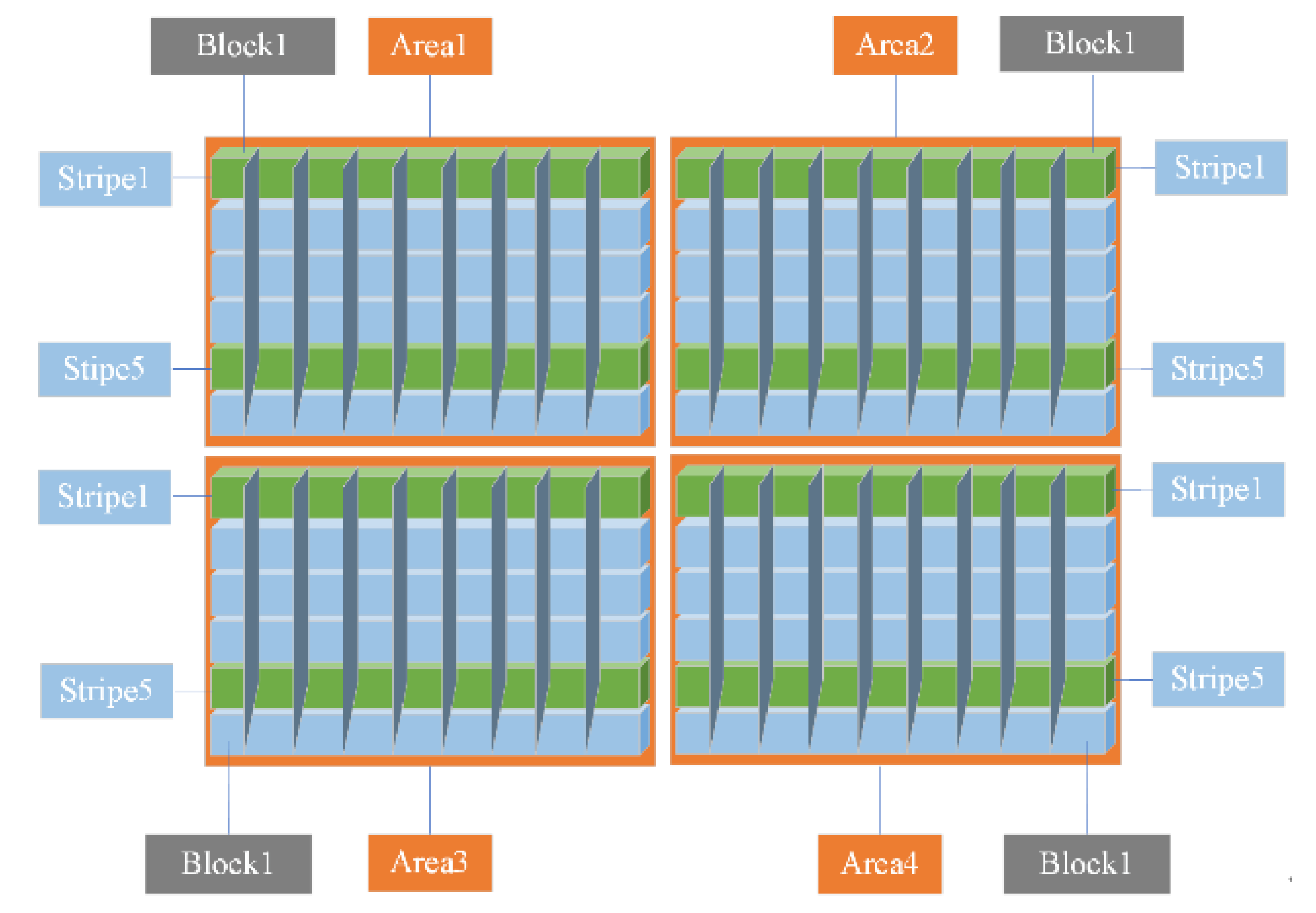
Figure 1. The horizontal stripe pre-cut mining method.
Sustainability 14 16379 g001
Figure 2. The upper slice and lower slice of a block.
Sustainability 14 16379 g002
Figure 3. The overall process cycle.
Sustainability 14 16379 g003
Figure 4. The boundary of this optimization.
Sustainability 14 16379 g004
Figure 5. Gantt chart for each area.
Sustainability 14 16379 g005
Figure 6. Gantt chart of operational progress of each stripe.
Sustainability 14 16379 g006
Figure 7. Gantt chart of ore block operation succession.
Sustainability 14 16379 g007
Figure 8. Equipment operational succession Gantt chart.
Sustainability 14 16379 g008
Figure 9. Statistical analysis chart for ore output.
Sustainability 14 16379 g009
Figure 10. Ore grade fluctuation graph.
Sustainability 14 16379 g010
Table 1. Indices and sets.
NameMeaning
ASet of areas, A = {A1, A2…, Ai}, i 1 , I
BiSet of stripes, Bi = {Bi1, Bi2, …, Bik}, i 1 , I , k 1 , K
CikSet of all blocks, C ik = { C ik 1 ,   C ik 2 ,     C ikn } ,   i 1 , I , k 1 , K , n 1 , E ( n 1 , N represents blocks of the upper slice, n N + 1 , E represents blocks of the lower slice)
DSet of horizontal drilling jumbos, D = {D1, D2, …, Dh}, h 1 , H
ZSet of downward drilling jumbos, Z = {Z1, Z2, …, Zr}, r 1 , R
CSet of charging dollies, C = {C1, C2, …, Cu}, u 1 , U
SSet of scaling jumbos, S = {S1, S2, …, Sx}, x 1 , X
LSet of LHDs, L = {L1, L2, …, Ly}, y 1 , Y
BSet of bolting jumbos, B = {B1, B2, …, Bw}, w 1 , W
FSet of filling pipelines, F = {F1, F2, …, Fv}, v 1 , V
JSet of processes, J = {J1, J2, …, Jm}, m 1 , 8 , J1 = 1 (Drilling), J2 = 2 (Charging), J3 = 3 (Blasting and ventilation), J4 = 4 (Scaling), J5 = 5 (Mucking), J6 = 6 (Bolting), J7 = 7 (Backfilling), J8 = 8 (Maintenance)
Table 2. Parameters.
NameMeaning
QiknOre volume of Cikn, t, n 1 , E
G+Upper limit of ore grade, g·t−1
GLower limit of ore grade, g·t−1
PhOperational efficiency of Dh, m/h
PrOperational efficiency of Zr, m/h
PuOperational efficiency of Cu, m/h
PwOperational efficiency of Bw, anchors/h
PvFilling capacity of Fv, m3/h
PyIdeal operational efficiency of Ly, t·m/h
ρ ikny Operational efficiency discount factor of Ly in Cikn, %, n 1 , E
φ ikn Distance factor from Cikn to the corresponding ore pass, m, n 1 , E
β Ventilation factor, n 1 , E
D i i + 1 Distance between adjacent areas, m
D i , k i , k Distance between different stripes in Ai, m, k = k ± 4
VelWalking speed of any equipment, m/h
qiknAvalanche ore volume per meter of Cikn, t/m, n 1 , E
ViknVolume of Cikn, m3, n 1 , E
GiknGrade of Cikn, g·t−1, n 1 , E
HiknHeight of Cikn, m, n 1 , N
NiknNumber of anchors per square meter of Cikn, anchors/m2, n 1 , N
Tmt,ikMaintenance time of Bik, h
Table 3. Variables.
Table 3. Variables.
NameMeaning
Lpao,iknTotal length of the blasting hole for Cikn, m, n 1 , E
Th,iknOperation time of Dh in Cikn, h, n 1 , N
Tr,iknOperation time of Zr in Cikn, h, n N + 1 , E
Tu,iknOperation time of Cu in Cikn, h, n 1 , E
Tven,iknBlasting and ventilation time in Cikn, h, n 1 , E
Tx,iknOperation time of Sx in Cikn, h, n 1 , N
Ty,iknOperation time of Ly in Cikn, h, n 1 , E
Tw,iknOperation time of Bw in Cikn, h, n 1 , N
Tv,ikBackfilling time of Fv in Bik, h
T work Its value is equal to any of {Th,ikn, Tr,ikn, Tu,ikn, Tx,ikn, Ty,ikn, Tw,ikn, Tv,ik, Tmt,ik }
TSiknmStarting time of jm in Cikn, h, n 1 , E , m 7 , 8
TSikmStarting time of jm in Bik, h, m = 7 , 8
TEiknmEnding time of jm in Cikn, h, n 1 , E , m 7 , 8
TEikmEnding time of jm in Bik, h, m = 7 , 8
DTikn,m,m+1The interval time between the ending time of jm and the starting time of jm+1 in Cikn, h, 1 , E , m 7 , 8
DTik,m,m+1The interval time between the ending time of jm and the starting time of jm+1 in Bik, h, m = 7
TM i , i + 1 Time of movement between Ai and Ai+1 with any equipment, h
TM ik , k Time of movement between Bik and B ik with any equipment, h
Bl siknm Number of blasting and ventilation for jm in Cikn, n 1 , E
Table 4. Main parameters of the stope.
Name of AreasNumber of StripesNumber of Ore BlocksTotal Quantities of Ores/Million TonsAverage Grade CuAverage Grade Co
Area11625649.592.420.12
Area22476686.932.180.14
Area431984115.162.880.08
Area12476869.782.730.12
Area62476870.112.740.12
Total1193798391.572.610.11
Table 5. Main technical parameters of mining equipment.
CategoryOperation ContentOperational CapacityAverage Movement SpeedNumber of Equipment
Horizontal drilling jumboDrilling horizontal holes40 m/h1000 m/h4
Downward drilling jumboDrilling vertical holes30 m/h1000 m/h2
Charging dollyDrilling holes for charging90 m/h1000 m/h3
Scaling jumboRoof scaling10 m2/h1000 m/h1
LHDOre mucking1500 t·m/h1000 m/h4
Bolting jumboAnchor support10 anchors/h1000 m/h3
Table 6. The results of single objective optimization and multi-objective optimization.
NameTotal
Time
(Days)
Stripe
Average
Time
(Days)
Process
Interval
(Days)
Block
Interval
(Days)
Equipment
Utilization
Rate
(%)
Ore Grade
Fluctuation
(Dimensionless)
Multi-objects587.67111.152914.54525.7551.250.06
Single objectTotal time549.43110.063620.48751.8149.620.34
Stripe
average time
567.91109.593561.94519.0750.240.11
Process
interval
600.61111.942734.91571.9446.190.24
Block interval626.16124.093381.57492.4447.940.19
Equipment
utilization rate
591.61116.803519.07749.5153.460.24
Ore grade
fluctuation
604.58121.093705.06934.8347.240.04
Table 7. Equipment utilization rate.
CategoryEquipment Utilization Rate
AverageMaximumMinimum
Horizontal drilling jumbo44.2742.9145.73
Downward drilling jumbo48.4347.9549.54
Charging dolly51.4349.2953.08
Scaling jumbo45.0545.0545.05
LHD63.8465.2861.34
Bolting jumbo46.7447.6745.33
Average51.2565.2845.05
Publisher’s Note: MDPI stays neutral with regard to jurisdictional claims in published maps and institutional affiliations.