Article

Determination of the Required Strength of Artificial Roof for the Underhand Cut-and-Fill Mine Using Field Measurements and Theoretical Analysis

1
Civil and Resource Engineering School, University of Science and Technology Beijing, Beijing 100083, China
2
School of Civil Engineering, Dalian University of Technology, Dalian 116024, China
3
Mining Research Institute of Baotou Steel (Group) Corp., Baotou 014030, China
4
Jinchuan Group Co., Ltd., Jinchang 737100, China
*
Author to whom correspondence should be addressed.
These authors contributed equally to this work and should be considered first authors.
Sustainability 2023, 15(1), 189; https://doi.org/10.3390/su15010189
Submission received: 14 November 2022 / Revised: 13 December 2022 / Accepted: 20 December 2022 / Published: 22 December 2022
(This article belongs to the Special Issue Advances in Intelligent and Sustainable Mining)

Abstract

:
For the underhand cut-and-fill mining method, to ensure safe and economic mining, a key issue is to correctly determine the required strength of the artificial roof made of cemented paste backfill (CPB). However, the determination of the required strength is typically based on historical experience and analytical beam formulas, resulting in the obtained required strength being unsuitable for the actual situation. Therefore, in order to determine the required strength of the CPB roof reasonably and accurately, field measurements based on sensors were proposed and carried out in the Jinchuan mine, and then formulas based on thick plate theory were derived to verify the measured results. The results show that the required strength obtained by field measurement is 0.325 MPa and that obtained by thick plate theory is 0.304 MPa, with an error of 6.78% between them, verifying the accuracy of the measurements. However, the strength standard currently used by Jinchuan is 0.59 MPa, which far exceeds the optimal strength and results in many additional, unnecessary expenses. To ensure economical mining, the span of the drift was enlarged from 5.0 m to 6.0 m based on the results of the actual measurements and the current production status of the mine. The measurements show that the maximum cumulative subsidence of the drift roof is 11.69 mm and the maximum convergence deformation of the sidewalls is 8.34 mm, which indicates that the stability of the span-enlarged drift is satisfactory. Meanwhile, enlarging the drift span allows for a 20% increase in production capacity per mining cycle. This field measurement method and theoretical analysis model can be used as an efficient guide to facilitate the design of underhand cut-and-fill mining.

1. Introduction

The backfill mining methods can not only effectively ensure the safety of the workspace and improve the ore recovery, but also serve to reduce the surface disposal of solid wastes (e.g., tailings, steel slag, waste rock) and promote the realization of “carbon neutralization and carbon peaking” [1,2,3]. Among other backfill mining methods, the underhand cut-and-filling method is characterized by top-down stoping, with workers and equipment mining under the protection of an artificial roof constructed by cemented paste backfill (CPB) [4,5]. Consequently, this method has been widely applied in the excavation of rare ore bodies with unstable ore and rock conditions at home and abroad [6,7].
The key to the safe application of the underhand cut-and-filling method is to determine the optimal required strength of the CPB roof [8,9,10,11]. The determination of the optimal required strength requires that the strength of the CPB roof and the maximum stress to which it is subjected are within a reasonable range [12,13]. If the strength of the CPB roof is too high in relation to the stress it is subjected to, the amount of cementitious material required will increase, which will increase the cost of mining [14]. On the contrary, it will cause the CPB roof to become unstable and the safety of staff and equipment will not be guaranteed [15]. However, there is no satisfactory method to determine the required strength of the CPB roof at home or abroad. Statistics show that over 50% of domestic and international mines use the empirical design method to determine the required strength of the CPB roof [16,17,18]. Historical experience is undoubtedly valuable, but as each mine is different, it is often difficult to find a suitable reference, and then the required strength determined by the empirical design method will not be the most reasonable. For instance, the undercut span of the Lanfranchi mine is 5.0 m, and the required strength of backfill is only approximately 0.5 MPa [17]. Meanwhile, the Jinchuan mine, the most successful one in applying the underhand cut-and-filling method in China, adopts the empirical design method to determine the required strength of the CPB roof. Due to the lack of scientific theoretical guidance, such as some theories that can determine the CPB strength reasonably and accurately, the required strength is set to 5.0 MPa for the same 5.0 m undercut span to increase mining safety [18]. Additionally, if the most suitable required strength can be obtained, the economic benefits and mining efficiency will be improved while ensuring the mining safety. Therefore, the reasonable determination of the required strength of the CPB roof is an essential research challenge.
The elasticity analysis method is a relatively scientific and quantitative method for determining CPB strength. Generally, the most suitable strength is obtained through multiplying a certain safety factor by the maximum stress in the CPB roof, which is calculated by elasticity analysis methods [19]. Hua et al. simplified the structure of the CPB roof to a simply supported beam for analysis and established a strength design model based on the elasticity analysis method [20]. Han et al. analyzed the damage pattern of a CPB roof based on a mechanics model of a simply supported beam and found that the most dangerous location is at the center of the lower surface of the CPB roof and that tensile damage generally occurs at this location [18]. Li et al. simplified the CPB roof to an elastic thin plate to study the stress distribution in the CPB roof [21]. Feng concluded that the structural characteristics of the CPB roof conform to those of an embedded beam, and adopted the semi-inverse solution method to derive the deflection equation and stress components of the CPB roof [22]. Zhao et al. suggest that when the thickness-to-span ratio of the CPB roof is greater than 1/4, the determination of strength using elastic beam and thin plate theory will result in significant errors [23]. Additionally, the elasticity analytical formulas indicate that the main factors determining the strength of the filler are the loads, the length of the drift, the thickness and the span of the CPB roof, and so on. In practice, structural parameters such as span are well determined, but loads are not, which greatly affects the accuracy of the calculations [24]. Currently, the combined beam principle and Pratt’s theory are often used to calculate the loads on the CPB roof [25]. Field measurements are the most reliable methods used to determine the loads. Although they are costly, they can add credibility to the results of the elastomeric calculations if they can be adopted.
In this work, to investigate the true maximum stress and then determine the optimal required strength of the CPB roof, we used sensors to monitor the stresses in the CPB roof at the Jinchuan mine. This is a novel study and one that has rarely been reported. Meanwhile, a new theory of thick plates was introduced to validate the measurement results. In order to improve the calculation accuracy of the theory, we also measured the loads on the CPB roof. Based on the field measurement results, the drift dimensions of the Jinchuan mine were optimized to improve the mining benefits and efficiency.

2. Engineering Background

The Jinchuan mine is the largest nickel mine in China, located in Jinchang City, Gansu Province, China. At present, a mechanized underhand cut-and-fill mining method is adopted in the Jinchuan mine. The drift section is rectangular in shape, with a span of 5.0 m and a height of 4.0 m [26]. The mass concentration of the filling slurry and cement/tailings ratio values are 77–79% and 1:4, respectively. Based on past tests, the CPB has a 28-day unconfined compressive strength (UCS) value and a tensile strength value of approximately 5.0 MPa and 0.59 MPa, respectively.
In practice, a key issue is the correct estimation of the required strength or stability of the artificial roof made of CPB [27]. If the required strength standard is set too high, unnecessary cement will be consumed. On the contrary, the safety of miners and equipment is not guaranteed, which can lead to interruptions in mining. For the Jinchuan mine, the lack of a corresponding scientific theory has led it to follow the example of other mines in determining the required strength. However, the strength obtained in this way differs significantly from the actual strength required by the Jinchuan mine. Therefore, it is necessary to carry out a series of investigations to reasonably determine the optimal required strength of CPB to effectively balance mining safety and costs.
On the other hand, the production capacity is severely restricted by the size of the drift. If the size of the drift can be further optimized based on the new, optimal required strength, it allows for increased production capacity and efficiency. However, increasing the size of the drift may cause the maximum tensile stress to exceed the tensile strength of the CPB roof, thereby reducing the safety of the mining operation. Consequently, based on the above analysis and introduction, it is a priority to determine the true maximum tensile stress in the CPB roof, whether to determine optimal required strength or to enlarge the size of the drift.

3. Field Engineering Measurement

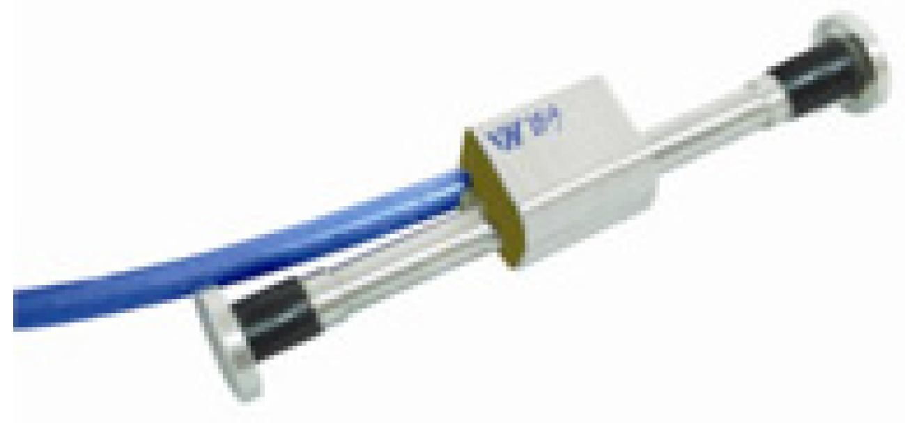
3.1. Measurement Instruments and Principles

3.1.1. Measurement of Stresses in the CPB Roof

The purpose of this test is to determine the maximum tensile stress in the CPB roof. Referring to the stress measurement methods in other concrete structures, a YC-YB-03 vibrating-wire strain gauge (see Figure 1) is selected to measure the stress in the CPB roof [28,29,30]. The selected model has a resolution of ±0.5% and a measurement range of ±1500 με. The vibrating-wire strain gauge consists mainly of a mounting support, vibrating wire, and coil. During the measurements, the deformation of the CPB roof changes the force of the vibrating wire synchronously, thereby changing the intrinsic vibration frequency of the wire. Then, the datalogger outputs a pulse signal, which excites the vibrating wire via a solenoid coil and records the vibration frequency of the wire. The measured change in frequency of the vibration wire is converted to strain using the metrological guidelines provided by the manufacturer. Finally, the stress in the CPB roof is calculated based on the stress–strain relationship of the CPB [31,32]. This relationship is described as follows:
σ = E ε
where E is the modulus of elasticity of the CPB and is set at 1.7 GPa, and ε is the maximum strain in the CPB roof.

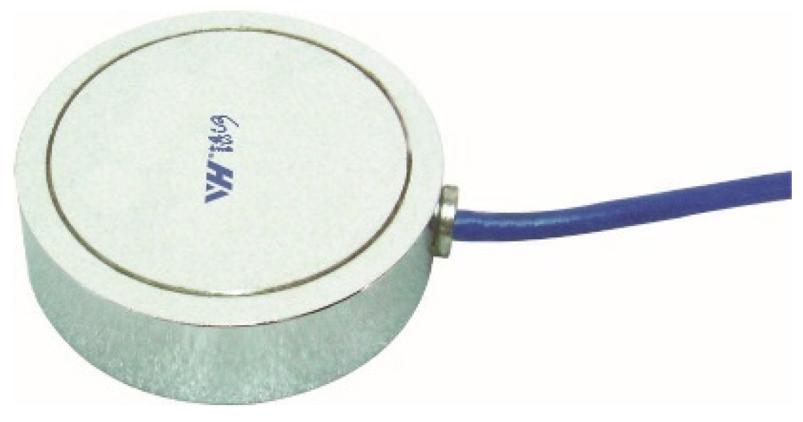
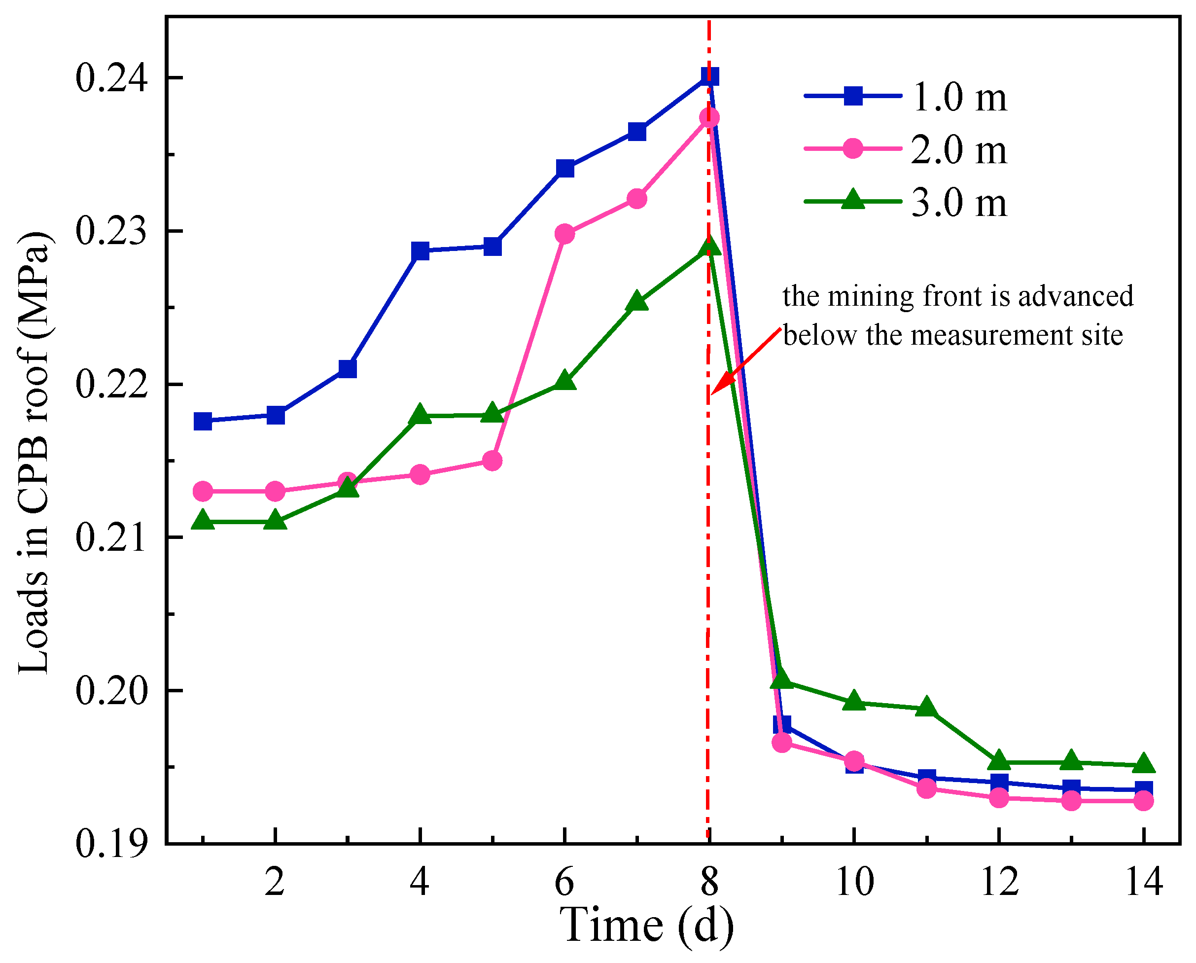
3.1.2. Measurement of Loads in the CPB Roof

In the CPB roof, vertical stress, i.e., the load, is measured using a vibrating-wire pressure cell. This parameter is crucial for improving the accuracy of the theoretical calculations. YH03-G10 vibrating-wire pressure cells (see Figure 2) with a measurement range of 0–2.0 MPa were selected. The vibrating-wire pressure cell is also a vibrating string sensor and the measurement principle is similar to that of the vibrating wire strain gauge. In addition, the vibrating-wire pressure cell has an internal calculation chip that automatically converts the measured data and outputs the vertical stress value directly, reducing errors and mistakes in manual conversion.

3.1.3. Additional Instrument

In order to measure the stress at different heights, a new steel platform (see Figure 3) was designed to mount the vibrating-wire strain gauge and vibrating-wire pressure cell. The steel platform is constructed with steel tubes and rebar welded together, with a length of 0.5 m, a width of 0.5 m, and a height of 3.0 m.

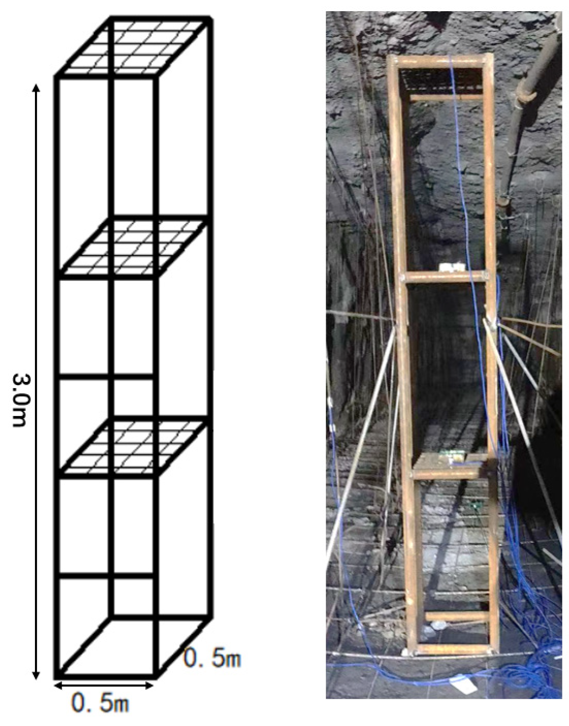
3.2. Measurement Procedure

The instruments have been installed, prior to backfilling, at a 1110 m level, 3rd sublevel, 46th drift. The location of the monitoring point is in the middle of the drift, and the drift has a length of 30 m. After the stope has been mined, the steel platform is installed in the empty stope. As shown in Figure 4, the vibrating-wire pressure cells are mounted on the steel platform with a height of 1.0 m, 2.0 m, and 3.0 m from the stope floor. The pressure-bearing surface of the vibrating-wire pressure cells should be oriented towards the roof of the stope. The vibrating wire strain gauge are installed on the steel platform with a height of 0.5 m, 1.0 m, 1.5 m and 2.0 m from the stope floor.
When the installation of the instruments has been completed, we connect the instruments to the datalogger with cables. To protect the cables from damage when mining the undercut, all cables are wrapped in a Ø20 steel pipe. Then, the backfill slurry is delivered to the stope through an underground pipeline, and the backfill slurry is allowed to cure and gain strength. A subsequent 48th undercut stope is then mined beneath the newly formed backfill. With the advance of undercut mining, the monitoring of the backfill is carried out simultaneously. The vibrating-wire pressure cells and vibrating-wire strain gauge are monitored every day until the end of mining by dataloggers. The detailed measurement process is shown in Figure 5.

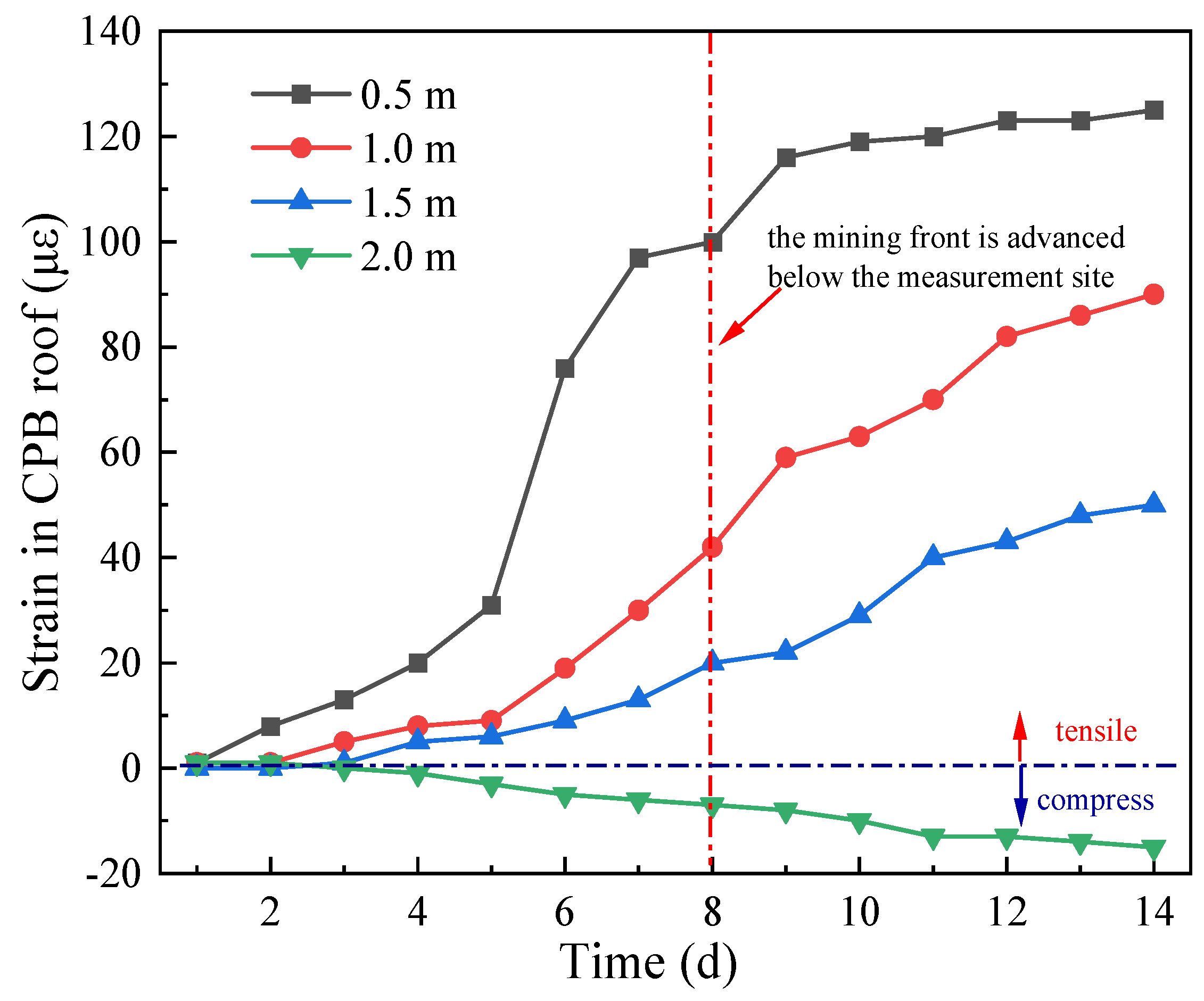
3.3. Measurement Results and Analysis

Measurements collected from CPB instruments over a period of around 15 days are shown in Figure 6 and Figure 7. Since the UCS of the CPB is much greater than its tensile strength, resulting in damage to the CPB mainly in the tensile pattern, the focus of this paper is on the maximum tensile stress to which the CPB is subjected during the mining process [33]. As the underhand mining front continues to advance, the cumulative strain at each measurement point increases. In addition, when the mining front is advanced below the measurement site, large changes in the measurements occur, indicating the significant deformation of the CPB roof at this time. Then, although the CPB roof exhibits continuous deformation, its deformation rate gradually decreases and eventually the measurements stabilize within a certain range. Compared to the measurements at other instruments installed at different heights, the results at the 0.5 m height show the greatest variation, with a maximum tensile strain value of 125. By substituting the maximum strain into Equation (1), the maximum tensile stress to which the CPB roof is subjected can be calculated as 0.216 MPa.
The distribution of the measurements varies considerably in the vertical direction. Positive measurements at 0.5 m, 1.0 m, and 1.5 m indicate tensile deformation of the CPB in this region, while negative measurements at 2.0 m indicate compressive deformation of the CPB above this height.
Measurements of the vibrating-wire pressure cell show that the loads at different locations increase slowly as the mining front advances, reaching the maximum loads when the mining front advances below the monitoring site. The maximum loads measured at different locations are not significantly different, with the vibrating-wire pressure cell at a height of 1.0 m in the CPB recording the maximum load of 0.240 MPa. This value will be used as an input parameter in the theoretical calculations in the following section. When the mining front advances beyond the monitoring site, the measurements of the vibrating-wire pressure cell decrease sharply, with a decrease of 25.03%. The reason for this phenomenon is that, during the excavation, a load-bearing arch is formed in the upper part of the excavation zone, which carries the self-weight of the overlying CPB and transfers the load to the two sides of the drift [34,35]. Finally, the loads stabilize as the mining workings continue to advance [36,37].

4. Theoretical Analysis

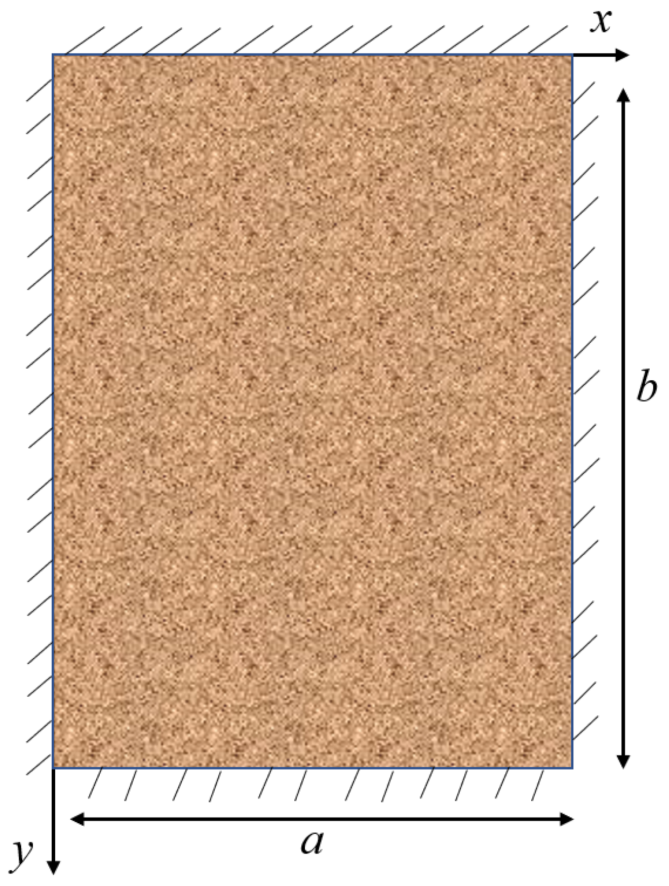
4.1. Establishment of the Thick Plate Mechanical Model

The two mechanical models commonly used to investigate the instability mechanism of a CPB roof are the simple beam model and the thin plate model [38]. However, with a drift width and height of 5.0 m and 4.0 m, respectively, the Jinchuan mine has an aspect ratio of more than 1/4. Then, if the above two models are adopted, there will be a large error in the calculation results. Consequently, this paper introduces the thick plate theory to determine the optimal required strength of the CPB roof.
The structure of the CPB roof is simplified to a four-sided, simply supported thick plate, and the mechanical model is shown in Figure 8.
The four sides of the thick plate are simply supported boundaries, so the deflection, bending moment, and rotation angle on the boundaries are all zero, which can be expressed as follows:
at x = 0 and x = a: w = 0, Mx = 0, ψy = 0
at y = 0 and y = b: w = 0, My = 0, ψx = 0
where b represents the length of the thick plate, a is the width of the thick plate, w is the deflection of the thick plate, Mx and My are the bending moments of the thick plate around the x-axis and y-axis, respectively, and ψx and ψy are the rotation angles of the thick plate around the x-axis and y-axis, respectively.
According to Vlasov’s theory [39], the equilibrium differential equations for a simply supported rectangular thick plate are
D 5 [ ( 1 u ) 2 ψ x + ( 1 + u ) Φ x + 1 2 x ( 2 w ) ] + G h 3 ( w x ψ x ) = 0
D 5 [ ( 1 u ) 2 ψ y + ( 1 + u ) Φ y + 1 2 y ( 2 w ) ] + G h 3 ( w y ψ y ) = 0
where h is the thickness of the thick plate; μ is the Poisson’s ratio of the thick plate; E is the modulus of elasticity of the thick plate; Φ = ψ x x + ψ y y . D is the bending stiffness of the thick plate, and G is the shear deformation modulus of the thick plate, which can be expressed as
D = E h 3 12 ( 1 μ 2 )
G = E 2 ( 1 + μ )
Then, the internal forces and moments of the CPB roof are expressed as follows:
M x = D 5 [ 4 ( ψ x x + μ ψ y y ) + ( 2 w x 2 + μ 2 w y 2 ) ]
M y = D 5 [ 4 ( ψ y y + μ ψ x x ) + ( 2 w y 2 + μ 2 w x 2 ) ]
M x y = D ( 1 μ ) 5 [ 2 ( ψ x y + ψ y x ) + 2 w x y ]
Q x = 2 3 G h ( w x ψ x )
Q y = 2 3 G h ( w x ψ y )
where Mxy is the moment of the thick plate, and Qx and Qy are the shear forces along the x and y directions, respectively.
Based on the boundary conditions, it may be useful to set the displacement functions for the deflection and the angle of rotation to be, respectively,
w = m = 1 n = 1 A m n sin m π x a sin n π y b
ψ x = m = 1 n = 1 B m n cos m π x a sin n π y b
ψ y = m = 1 n = 1 C m n sin m π x a cos n π y b
where Amn, Bmn, and Cmn are coefficients related to the deformation of the thick plate; m and n are positive integers.
The boundary conditions of the plate are all satisfied, and the load is expanded into the form of double triangular series:
q ( x , y ) = m = 1 n = 1 q m n sin m π x a sin n π y b
where q(x,y) is the load function of the thick plate and qmn is the coefficient of the double delta series.
Using the orthogonality of trigonometric functions, the qmn can be expressed as
q m n = 4 a b 0 a 0 b q ( x , y ) sin m π x a sin n π y b d x d y
Assuming that a uniform load is distributed above the CPB roof,
q(x,y) = q0
where q0 is the maximum load.
Substituting Equation (16) into Equation (15) yields
q m n = 16 q 0 π 2 m n
Substituting Equations (11)–(13) and (15) into the system of differential Equations (6)–(10), the expressions Amn, Bmn, and Cmn are obtained:
A m n = { 1 + 6 D π 2 5 G h [ ( m a ) 2 + ( n b ) 2 ] } q m n D π 4 [ ( m / a ) 2 + ( n / b ) 2 ] 2
B m n = { 1 3 D π 2 10 G h [ ( m a ) 2 + ( n b ) 2 ] } m q m n a D π 3 [ ( m / a ) 2 + ( n / b ) 2 ] 2
C m n = { 1 3 D π 2 10 G h [ ( m a ) 2 + ( n b ) 2 ] } n q m n b D π 3 [ ( m / a ) 2 + ( n / b ) 2 ] 2
With guaranteed accuracy, allow m = n = 1, and then combine Equations (18)–(20) and (11)–(13) to derive the expressions for the moments and deflections of the thick plate as
w = 16 q 0 D π 6 { { 1 + 6 D π 2 5 G h [ ( 1 a ) 2 + ( 1 b ) 2 ] } 1 [ ( 1 / a ) 2 + ( 1 / b ) 2 ] 2 sin π x a sin π y b + { 1 + 6 D π 2 5 G h [ ( 1 a ) 2 + ( 3 b ) 2 ] } 1 3 [ ( 1 / a ) 2 + ( 3 / b ) 2 ] 2 sin π x a sin 3 π y b + { 1 + 6 D π 2 5 G h [ ( 3 a ) 2 + ( 1 b ) 2 ] } 1 3 [ ( 3 / a ) 2 + ( 1 / b ) 2 ] 2 sin 3 π x a sin π y b + { 1 + 6 D π 2 5 G h [ ( 3 a ) 2 + ( 3 b ) 2 ] } 1 9 [ ( 3 / a ) 2 + ( 3 / b ) 2 ] 2 sin 3 π x a sin 3 π y b }
ψ x = 16 q 0 D π 5 { { 1 3 D π 2 10 G h [ ( 1 a ) 2 + ( 1 b ) 2 ] } 1 a [ ( 1 / a ) 2 + ( 1 / b ) 2 ] 2 cos π x a sin π y b + { 1 3 D π 2 10 G h [ ( 1 a ) 2 + ( 3 b ) 2 ] } 1 3 a [ ( 1 / a ) 2 + ( 3 / b ) 2 ] 2 cos π x a sin 3 π y b + { 1 3 D π 2 10 G h [ ( 3 a ) 2 + ( 1 b ) 2 ] } 1 a [ ( 3 / a ) 2 + ( 1 / b ) 2 ] 2 cos 3 π x a sin π y b + { 1 3 D π 2 10 G h [ ( 3 a ) 2 + ( 3 b ) 2 ] } 1 3 a [ ( 3 / a ) 2 + ( 3 / b ) 2 ] 2 cos 3 π x a sin 3 π y b }
ψ y = 16 q 0 D π 5 { { 1 3 D π 2 10 G h [ ( 1 a ) 2 + ( 1 b ) 2 ] } 1 b [ ( 1 / a ) 2 + ( 1 / b ) 2 ] 2 sin π x a cos π y b + { 1 3 D π 2 10 G h [ ( 1 a ) 2 + ( 3 b ) 2 ] } 1 b [ ( 1 / a ) 2 + ( 3 / b ) 2 ] 2 sin π x a cos 3 π y b + { 1 3 D π 2 10 G h [ ( 3 a ) 2 + ( 1 b ) 2 ] } 1 3 b [ ( 3 / a ) 2 + ( 1 / b ) 2 ] 2 sin 3 π x a cos π y b + { 1 3 b [ ( 3 / a ) 2 + ( 3 / b ) 2 ] 2 sin 3 π x a cos 3 π y b }
Substituting Equations (21)–(23) into Equations (6) and (7), respectively, it is clear that the bending moment has maximum values at x = a/2 and y = b/2, which can be expressed as
M x max = 16 q 0 π 4 { b 2 + μ a 2 a 2 b 2 [ ( 1 / a ) 2 + ( 1 / b ) 2 ] 2 b 2 + 9 μ a 2 3 a 2 b 2 [ ( 1 / a ) 2 + ( 3 / b ) 2 ] 2 9 b 2 + μ a 2 3 a 2 b 2 [ ( 3 / a ) 2 + ( 1 / b ) 2 ] 2 + b 2 + μ a 2 a 2 b 2 [ ( 3 / a ) 2 + ( 3 / b ) 2 ] 2 }
M y max = 16 q 0 π 4 { a 2 + μ b 2 a 2 b 2 [ ( 1 / a ) 2 + ( 1 / b ) 2 ] 2 9 a 2 + μ b 2 3 a 2 b 2 [ ( 1 / a ) 2 + ( 3 / b ) 2 ] 2 a 2 + 9 μ b 2 3 a 2 b 2 [ ( 3 / a ) 2 + ( 1 / b ) 2 ] 2 + a 2 + μ b 2 a 2 b 2 [ ( 3 / a ) 2 + ( 3 / b ) 2 ] 2 }
The maximum tensile stresses occur at the lower surface of the CPB roof and are calculated according to the following formulas:
σ x max | z = h 2 = 12 M x max h 3 z
σ y max | z = h 2 = 12 M y max h 3 z
Then, the maximum tensile stresses in the CPB roof are
σ x max = 96 q 0 π 4 h 2 { b 2 + μ a 2 a 2 b 2 [ ( 1 / a ) 2 + ( 1 / b ) 2 ] 2 b 2 + 9 μ a 2 3 a 2 b 2 [ ( 1 / a ) 2 + ( 3 / b ) 2 ] 2 9 b 2 + μ a 2 3 a 2 b 2 [ ( 3 / a ) 2 + ( 1 / b ) 2 ] 2 + b 2 + μ a 2 a 2 b 2 [ ( 3 / a ) 2 + ( 3 / b ) 2 ] 2 }
σ y max = 96 q 0 π 4 h 2 { a 2 + μ b 2 a 2 b 2 [ ( 1 / a ) 2 + ( 1 / b ) 2 ] 2 9 a 2 + μ b 2 3 a 2 b 2 [ ( 1 / a ) 2 + ( 3 / b ) 2 ] 2 a 2 + 9 μ b 2 3 a 2 b 2 [ ( 3 / a ) 2 + ( 1 / b ) 2 ] 2 + a 2 + μ b 2 a 2 b 2 [ ( 3 / a ) 2 + ( 3 / b ) 2 ] 2 }
where σxmax is the maximum tensile stress in the x direction and σymax is the maximum tensile stress in the y direction.
During the bending process of the CPB roof, tensile damage occurs when the maximum tensile stress in the CPB roof exceeds the designed tensile strength of the CPB. Consequently, based on the maximum tensile stress calculated by the thick plate theory, a model can be established to determine the optimal required strength of the CPB roof.
σ t = f × max { σ x max , σ y max }
where σt is the optimal required strength, and f is the safety factor, generally taken as 1.5.

4.2. Calculation of the Stress

In the above research, the load has been measured to be 0.240 MPa. The other detailed input parameters are shown in Table 1. Then, the load and the structural parameters of the drift were substituted into the thick plate model to calculate the maximum tensile stress to which the CPB roof was subjected to be 0.203 MPa. As the thick plate theory has been validated by many scholars and the parameter of load required for the calculations is measured, the results are highly reliable. They can be corroborated with the experimental results.

5. Comparison of Experimental and Theoretical Calculation Results and Determination of Required Strength

The maximum tensile stress in the CPB roof obtained by actual measurement is 0.216 MPa and that obtained by theoretical calculation of the thick plate is 0.203 MPa, and the error between the two is 6.78%. This error is acceptable because of the many uncertainties in the measurement process and indicates that the maximum tensile stress obtained using these methods is accurate.
The results of theoretical calculation and field monitoring indicate that the maximum tensile stress in the CPB roof is 0.216 MPa. Then, multiplying this value by a safety factor of 1.5 yields the optimal required strength of 0.325 MPa for the Jinchuan mine. In addition, the tensile strength of the CPB is generally 12% of its compressive strength, so the optimum compressive strength is 2.710 MPa. Currently, the compressive strength of the CPB the Jinchuan mine is 5 MPa, which exceeds the optimum by 2.290 MPa (see Figure 9), proving that the current strength standard is set too high and that this will lead to many unnecessary expenditures. Meanwhile, it also indicates that the mix proportion of CPB or the structural parameters of the drift need to be optimized to achieve the most reasonable difference between the required strength and the maximum tensile stress. In practice, the mine’s production capacity is severely constrained by the size of the drifts. If the size of the drifts were to be expanded, this would increase the blasting efficiency and maximize the capacity of the equipment, thereby increasing the production capacity. Additionally, increasing the height of the drifts would lead to inconvenient operations onsite. Therefore, based on the rock conditions and production capacity of the mine, we decided to only increase the span of the drifts from 5.0 m to 6.0 m.

6. Engineering Application

After investigation, the strength of CPB in the Jinchuan mine exceeds the optimum value by a large margin, proving that the current strength standard is set too high. Consequently, in order to make the current strength fully functional, the span of the drift was enlarged from 5 m to 6 m based on the results of the actual measurements and the current production status of the mine. Before the large-scale application of wide-span drift mining, it is necessary to carry out a series of theoretical analyses as well as experiments to prove its safety. Through calculation using the thick plate theory, the maximum tensile stress in the CPB is 0.296 MPa after the span is enlarged, which is less than the tensile strength of the CPB. After calculation, the safety factor is 1.99 when the span of the drifts is 6 m. This safety factor allows for the safe exploitation of the Jinchuan mine. However, this is only a theoretical analysis—what is the real stability of the drift after the span has been enlarged? Furthermore, to evaluate the real stability of drift with extended span, we monitored the deformation of the drift roof and two sidewalls.

6.1. Monitoring Scheme

The JSS30A convergence instrument was selected to monitor the deformation of the drift roof and two sidewalls in the 25th drift in the 1110 m level. In order to obtain adequate and valid measurements, three sections were arranged in the drift for monitoring. In addition, five monitoring points were assigned within the same section. As shown in Figure 10, measuring point A1 was positioned in the middle of the roof and measuring points A2 and A3 were arranged at a position 0.7 m away from the sidewalls. The measurement points C and B were placed on the sidewalls of the drift at the same level and 1.5 m from the floor.

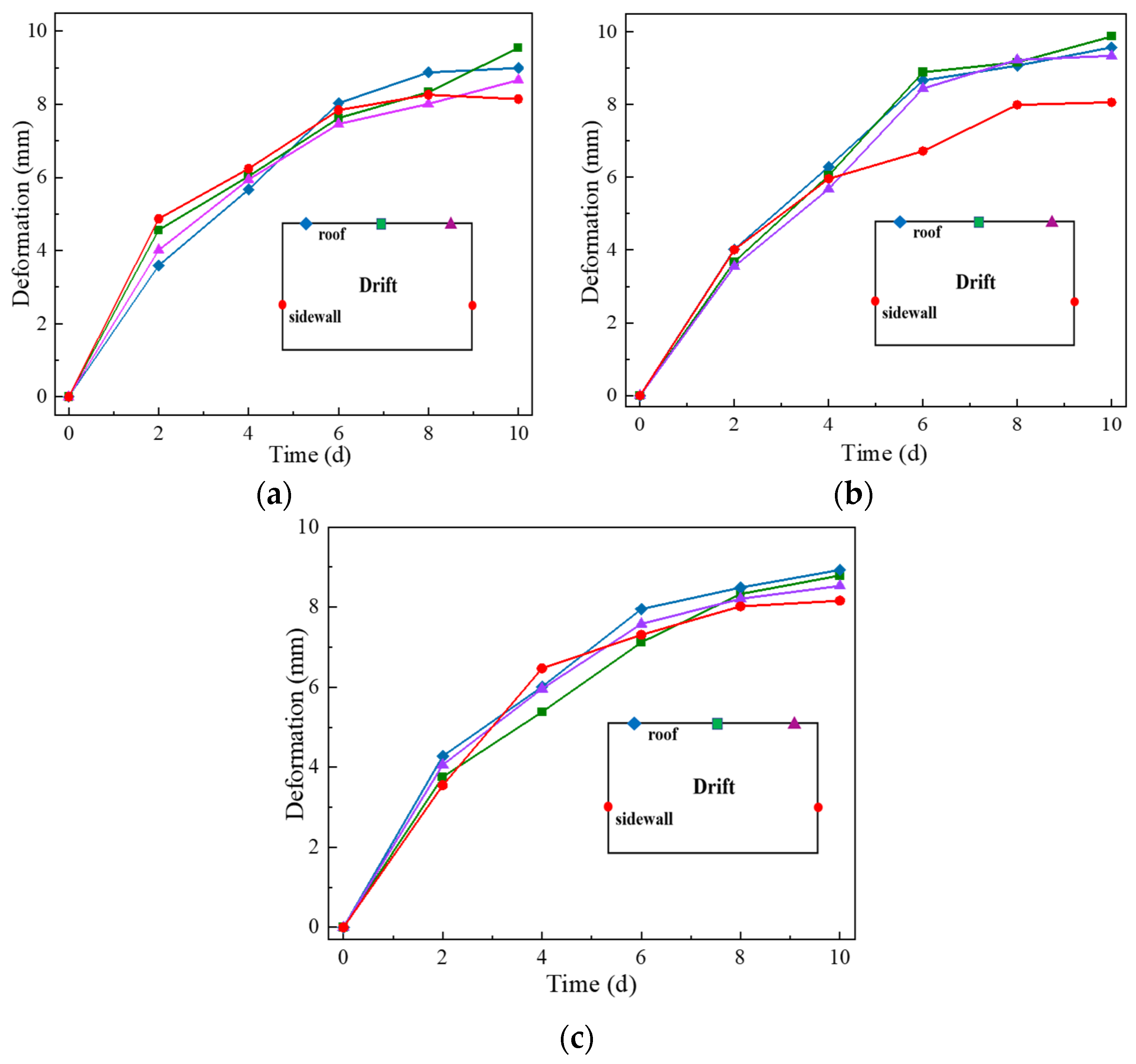
6.2. Monitoring and Application Results

As shown in Figure 11, the measurements show that the maximum subsidence of the drift roof is 11.69 mm and the maximum convergence deformation of the sidewalls is 8.34 mm, which indicates that the stability of the drift is satisfactory. The subsidence in the middle of the plate is slightly larger than that on the sides, which is consistent with the deformation pattern of the thick plate model. During the whole monitoring period, the cumulative convergent deformation of the roof and sidewalls of each monitoring section increases with time, but the deformation rates of the measured sections gradually decrease, indicating that the drift gradually tends to be stable.
The results of theoretical analysis and field monitoring show that that it is reasonable and safe to extend the span of the drift. Meanwhile, enlarging the span of the drift can increase the ore output of each blast by 20% and improve the production efficiency. The expansion of the drift span leads to a relatively low clamping force, so the powder factor will be further reduced and the cost will be reduced. Furthermore, the enlarged span of the drift has changed the existing “frequent short steps” mining model, allowing for more streamlined mining management.

7. Conclusions

In practice, the required strength of an artificial roof made of CPB plays a key role in the later successful application of the underhand cut-and-fill mining method. Therefore, in this study, we adopted the methods of field measurement and theoretical analysis to determine the required strength reasonably and accurately. Firstly, the true maximum tensile stress of 0.216 MPa in the CPB roof of the Jinchuan mine was measured using a vibrating string strain gauge. Then, multiplying this value by a safety factor of 1.5 yielded the optimal required strength of 0.325 MPa for the Jinchuan mine. Additionally, based on the thick plate theory, an analytical solution for the distribution of tensile stresses in the CPB roof was derived and a formula for the maximum tensile stress in the CPB roof was obtained. The maximum load of 0.240 MPa in the CPB roof was measured. Then, by substituting the maximum load obtained through actual measurements into the formula, the maximum tensile stress in the CPB roof was calculated to be 0.203 MPa. The error between theoretical calculations and actual measurements was only 6.78%, verifying the accuracy of the measurements. Currently, the tensile strength of CPB in the Jinchuan mine is 0.59 MPa, which exceeds the optimum by a large margin, proving that the current strength standard is set too high. Consequently, in order to make the current strength fully functional, the span of the drift was enlarged from 5 m to 6 m based on the results of the actual measurements and the current production status of the mine. The measurements show that the maximum cumulative subsidence of the drift roof is 11.69 mm and the maximum convergence deformation of the sidewalls is 8.34 mm, which indicates that the stability of the span-enlarged drift is satisfactory. Meanwhile, enlarging the drift span has increased the ore production by 20% per mining cycle, resulting in a significant improvement in production efficiency. This investigation is of great significance to guide the safe, efficient, and economical mining of the Jinchuan mine.

Author Contributions

Conceptualization, B.H., K.J., J.W. and Y.H.; Formal analysis, B.H.; Funding acquisition, B.H.; Investigation, B.H., K.J., J.W., S.W., P.Z. and Y.H.; Methodology, B.H., K.J., J.W. and P.Z.; Supervision, B.H. and S.W.; Validation, K.J., S.W. and Y.H.; Visualization, K.J. and P.Z.; Writing—original draft, B.H., K.J., J.W., S.W., P.Z. and Y.H.; Writing—review and editing, B.H., K.J., J.W., S.W., P.Z. and Y.H. All authors have read and agreed to the published version of the manuscript.

Funding

This research was funded by the National Key R&D Program of China, grant number 2018YFC1900603.

Institutional Review Board Statement

Not applicable.

Informed Consent Statement

Not applicable.

Data Availability Statement

All data generated or analyzed during this study are included in this published article.

Conflicts of Interest

The authors declare no conflict of interest.

References

  1. Fu, J.; Wang, J.; Song, W. Damage constitutive model and strength criterion of cemented paste backfill based on layered effect considerations. J. Mater. Res. Technol. 2020, 3, 6073–6084. [Google Scholar] [CrossRef]
  2. Li, H.; Ji, K.; Tao, Y.; Tang, C. Modelling a Novel Scheme of Mining Geothermal Energy from Hot Dry Rocks. Appl. Sci. 2022, 12, 11257. [Google Scholar] [CrossRef]
  3. Xu, W.; Cao, P. Fracture behavior of cemented tailing backfill with pre-existing crack and thermal treatment under three-point bending loading: Experimental studies and particle flow code simulation. Eng. Fract. Mech. 2018, 195, 129–141. [Google Scholar] [CrossRef]
  4. Gao, T.; Sun, W.; Liu, Z.; Cheng, H. Investigation on Fracture Characteristics and Failure Pattern of Inclined Layered Cemented Tailings backfill. Constr. Build. Mater. 2022, 343, 128110. [Google Scholar] [CrossRef]
  5. Chang, Q.; Sun, Y.; Leng, Q.; Liu, Z.; Zhou, H.; Sun, Y. Stability Analysis of Paste Filling Roof by Cut and Fill Mining. Sustainability 2021, 13, 10899. [Google Scholar] [CrossRef]
  6. Qin, S.; Cao, S.; Yilmaz, E. Employing U-shaped 3D printed polymer to improve flexural properties of cemented paste backfills. Constr. Build. Mater. 2022, 320, 126296. [Google Scholar] [CrossRef]
  7. Feng, F.; Li, D.; Li, X.; Guo, Z.; Wang, S.; Chen, Y. Novel underhand cut-and-fill stoping method and mechanical analysis of overlying backfill. Int. J. Geomech. 2017, 7, 04017004. [Google Scholar] [CrossRef]
  8. Mitchell, R.J. Sill mat evaluation using centrifuge models. Min. Sci. Technol. 1991, 3, 301–313. [Google Scholar] [CrossRef]
  9. Keita, A.; Jahanbakhshzadeh, A.; Li, L. Numerical analysis of the stability of arched sill mats made of cemented backfill. Int. J. Rock Mech. Min. Sci. 2021, 2, 104667. [Google Scholar] [CrossRef]
  10. Hughes, P.B.; Pakalnis, R.; Hitch, M.; Corey, G. Composite paste barricade performance at Goldcorp Inc. Red Lake Mine, Ontario, Canada. Int. J. Min. Reclam. Environ. 2010, 2, 138–150. [Google Scholar] [CrossRef]
  11. Grabinsky, M.; Bawden, W.; Thompson, B. Required Plug Strength for Continuously Poured Cemented Paste Backfill in Longhole Stopes. Mining 2021, 1, 80–99. [Google Scholar] [CrossRef]
  12. Ma, S.-W.; Hu, J.-H.; Qin, Y.-G.; Ren, Q.-F.; Yang, D.-J. Bearing mechanism and thickness optimization of ore roof in bauxite stope. Trans. Nonferr. Met. Soc. China 2022, 1, 285–295. [Google Scholar] [CrossRef]
  13. Fan, W.L. Study and Application of the Artificial Roof Structure for Medium Thickness Steep Fractured Ore Mining. Ph.D. Thesis, Central South University, Changsha, China, 2013. [Google Scholar]
  14. Shang, X.Y.; Li, X.B.; Peng, K.; Xu, X. Optimization of drift in extremely fractured ore-body based on safety coefficient and reliability analysis. J. Cent. South Univ. 2016, 7, 2390–2397. [Google Scholar]
  15. Han, B.; Zhang, S.; Deng, J. Determining method of backfill strength for underhand drift cut-and-fill stoping based on reliability theory. J. China Univ. Min. Technol. 2006, 3, 372–376. [Google Scholar]
  16. Kuang, D.Y.; Zhou, Y.C.; Wan, C.C.; Liu, L.S.; Pan, G.H. Study on design parameters of artificial roof of downward drift mining method in Sanshandao gold mine. Nonferr. Met. 2021, 6, 99–103. [Google Scholar]
  17. Han, B. Reliability Analysis of Filling Body and Optimization of the Control of the Stope Pressure of the First Orebody in Jinchuan No. 2 Mining Area. Ph.D. Thesis, Central South University, Changsha, China, 2004. [Google Scholar]
  18. Ma, C.N. Research of the Mechanical Behavior and Function of Backfilling with Inderhand Cut-and-Fill Method in Jinchuan No. 2 Mine. Ph.D. Thesis, Central South University, Changsha, China, 2011. [Google Scholar]
  19. Wu, A.X.; Zhang, A.Q.; Wang, H.J.; Rong, K. The mechanical model for the paste false roof and finite element analysis. J. Min. Saf. Eng. 2017, 3, 587–593. [Google Scholar]
  20. Hua, X.Z.; Sun, H.H. Study on Main Parameters of Underhand Heading Filling with High-Water Content Tailings. J. China Univ. Min. Technol. 2001, 1, 101–104. [Google Scholar]
  21. Li, X.S.; Li, X.B.; Gong, Y.C.; Liu, Z.X.; Zhao, Y.Z. Mechanical model and stability analysis for long-span artificial roof with backfill. Ming Metall. Eng. 2018, 6, 23–28+38. [Google Scholar]
  22. Feng, F.; Huang, W.P.; Guo, Z.P.; Wang, Y.; Wang, E. Stability analysis of cemented filling roof under the condition of shallow downward single route type of roadway. J. Min. Saf. Eng. 2016, 6, 1089–1095. [Google Scholar]
  23. Zhao, G.Y.; Zhou, S.X. Determining safe thickness of roof in subsea mining based on thick plate theory. Chin. J. Geol. Hazard Control 2015, 4, 60–66. [Google Scholar]
  24. Jiang, H.G.; Yu, T.C.; Liu, G.S.; Yang, L. Strength requirement for cemented backfill in rectangular drift of underhand cut-and-fill mining in Maoping mine. Nonferrous Met. 2022, 3, 42–49. [Google Scholar]
  25. Fan, W.L.; Li, X.B.; Zhou, Z.L. Based on the theory of reliability of reinforced concrete false roof strength and reinforcement design research. Min. Metall. Eng. 2013, 4, 30–35. [Google Scholar]
  26. Han, B.; Ji, K.; Singsh, B.P.M.; Qiu, J.; Zhang, P. An Optimization Method for Mix Proportion of Wet-Mix Shotcrete: Combining Artificial Neural Network with Particle Swarm Optimization. Appl. Sci. 2022, 3, 1698. [Google Scholar] [CrossRef]
  27. Xiao, Y.L.; Han, B. Analysis on the drift stability of downward drift filling mining in Longshou mine. Min. Res. Dev. 2021, 8, 36–40. [Google Scholar]
  28. Kang, J.F.; Sui, C.E.; Zhang, X.T. Concrete Thermal Stress Analysis Based on Observational Data from Concrete Strain Meter. J. Exp. Mech. 2013, 1, 121–126. [Google Scholar]
  29. Zhu, Q.; Li, T.; Zhang, H.; Ran, J.; Li, H.; Du, Y.; Li, W. True 3D geomechanical model test for research on rheological deformation and failure characteristics of deep soft rock roadways. Tunn. Undergr. Space Technol. 2022, 128, 104653. [Google Scholar] [CrossRef]
  30. Tesarik, D.R.; Seymour, J.B.; Yanske, T.R. Long-term stability of a backfilled room-and-pillar test section at the Buick Mine, Missouri, USA. Int. J. Rock Mech. Min. Sci. 2009, 7, 1182–1196. [Google Scholar] [CrossRef]
  31. Guo, Z.P.; Feng, F.; Huang, R.F.; Wang, C.; Li, W.; Wang, E.Y. Study on mechanical behavior and stability of overlying backfilling body in single roadway drift stoping method. Met. Mine 2014, 4, 60–64. [Google Scholar]
  32. Gu, W.; Zhang, L.-Y.; Tan, Z.-X.; Deng, K.-Z. Study on roof stability of open backfilling based on elastic plate model. J. Min. Saf. Eng. 2013, 6, 886–891. [Google Scholar]
  33. Chen, Q.; Zhu, L.; Wang, Y. The carbon uptake and mechanical property of cemented paste backfill carbonation curing for low concentration of CO2. Sci. Total Environ. 2022, 852, 158516. [Google Scholar] [CrossRef]
  34. Chen, Q.; Sun, S.; Wang, Y. In-situ remediation of phosphogypsum in a cement-free pathway: Utilization of ground granulated blast furnace slag and NaOH pretreatment. Chemosphere 2022, 313, 137412. [Google Scholar] [CrossRef] [PubMed]
  35. Chen, Q.; Zhang, Q.; Wang, Y. Highly-efficient fluoride retention in on-site solidification/stabilization of phosphogypsum: Cemented paste backfill synergizes with poly-aluminum chloride activation. Chemosphere 2022, 309, 136652. [Google Scholar] [CrossRef] [PubMed]
  36. Pagé, P.; Li, L.; Yang, P.; Simon, R. Numerical investigation of the stability of a base-exposed sill mat made of cemented backfill. Int. J. Rock Mech. Min. Sci. 2019, 114, 195–207. [Google Scholar] [CrossRef]
  37. Yang, S.; Liu, J.; Zhang, Z.B. Study on the Extraction of Multi level Continuous I arge Rib Pillar and its Engineering Practice. Min. Res. Dev. 2021, 7, 1–8. [Google Scholar]
  38. Wang, J.; Qiao, D.P.; Li, G.T.; Liu, Y.H.; Zhang, X. Strength model and its application of downward drift filling roof based on thick plate theory. J. China Coal Soc. 2022, 3, 2. [Google Scholar]
  39. Cheng, X.S. Applied Theory of Plates and Shells; Shandong Science & Technology Press: Ji’nan, China, 1989. [Google Scholar]
Figure 1. Vibrating-wire strain gauge.
Sustainability 15 00189 g001
Figure 2. Vibrating-wire pressure cell.
Sustainability 15 00189 g002
Figure 3. Steel platform for mounting instruments.
Sustainability 15 00189 g003
Figure 4. Diagram of measurement point layout: (a) load measurement; (b) stress measurement.
Sustainability 15 00189 g004
Figure 5. The process of field measurements.
Sustainability 15 00189 g005
Figure 6. The strain change of the CPB roof.
Sustainability 15 00189 g006
Figure 7. The load change of the CPB roof.
Sustainability 15 00189 g007
Figure 8. Mechanical model of thick plate theory.
Sustainability 15 00189 g008
Figure 9. Comparison of field measurements and theoretical calculations.
Sustainability 15 00189 g009
Figure 10. Layout of the drift deformation monitoring.
Sustainability 15 00189 g010
Figure 11. Deformation law of the drift: (a) Section 1; (b) Section 2; (c) Section 3.
Sustainability 15 00189 g011
Table 1. Input parameters of the models.
ItemsHeight (m)Span (m)Length (m)Poisson RatioLoad (MPa)
Value4.05350.210.240
Disclaimer/Publisher’s Note: The statements, opinions and data contained in all publications are solely those of the individual author(s) and contributor(s) and not of MDPI and/or the editor(s). MDPI and/or the editor(s) disclaim responsibility for any injury to people or property resulting from any ideas, methods, instructions or products referred to in the content.

