Article

Cooling of Heated Blocks with Triangular Guide Protrusions Simulating Printed Circuit Boards

1
Mechanical Engineering Department, School of Natural and Applied Sciences, Bursa Uludag University, Gorukle Campus, TR-16059 Bursa, Turkey
2
Mechanical Engineering Department, Faculty of Engineering and Architecture, Bitlis Eren University, Rahva Campus, TR-13000 Bitlis, Turkey
3
Southern Marmara Development Agency, Paşaalanı Mah., A. Gaffar Okkan Cad., No: 28/1, Karasi, TR-10020 Balıkesir, Turkey
4
Mechanical Engineering Department, Faculty of Engineering and Natural Sciences, Bursa Technical University, Mimar Sinan Mah., Mimar Sinan Bulvari, Eflak Cad., No: 177, Yildirim, TR-16310 Bursa, Turkey
5
Mechanical Engineering Department, Faculty of Engineering, Bursa Uludag University, Gorukle Campus, TR-16059 Bursa, Turkey
*
Author to whom correspondence should be addressed.
Sustainability 2022, 14(23), 15856; https://doi.org/10.3390/su142315856
Submission received: 3 October 2022 / Revised: 4 November 2022 / Accepted: 16 November 2022 / Published: 28 November 2022
(This article belongs to the Special Issue Energy Efficient Sustainable Cooling Systems)

Abstract

:
There is no study that investigates triangular guide protrusions including their systematical geometrical changes together with the effects of channel height in the open literature in the context of the authors’ knowledge. Moreover, the number of laminar studies is less than turbulent studies, whereas low velocity or natural convection cases are still important, especially for small devices in small PCB passages. The objective of this study is to investigate numerically the effects of triangular guide protrusions for the enhancement of heat transfer from the blocks’ simulated electronic components in laminar flow conditions. Two-dimensional, incompressible, steady, and laminar flow analysis was performed to predict fluid flow and heat transfer characteristics for three heated blocks in a PCB (printed circuit board) passage with triangular guide protrusions mounted on the upper wall. The Galerkin finite element method of weighted residuals was used to discretize conservation equations. The effects of the channel expansion ratio and inlet velocity were investigated for five geometrical cases. If the size of the protrusions is increased, the existence of protrusions starts to affect the flow patterns on the lower wall. The size of the last protrusion controls the flow structure downstream of the last block. On the upper wall, after the last protrusion, a recirculation is formed and the length of the recirculation increases with an increasing Re number. Moreover, the reattachment length of recirculation after the last block increases with an increasing Reynolds number for a fixed expansion ratio. Expansion ratio and inflow conditions caused by blocks and protrusions have a great influence on the formation of secondary recirculation in addition to the Reynolds number. Heat transfer increases with increasing sizes of upper triangular protrusions. Maximum overall heat transfer enhancement is provided as 47.7% with the geometry of the maximum sized protrusions for the channel height of 3 h. In the case of 4 h, the maximum overall heat transfer enhancement is 24.21%. These enhancements in heat transfer that can be encountered in PCB cooling applications may help the PCB cooling designers.

1. Introduction

Towards the 21st century, together with rapid progression in electronic and telecommunication industries as a result of the significant increase in packaging density, heat transfer enhancement techniques for air-cooled electronic packages gain importance owing to their simplicity, reliability, and lower hardware cost because traditional air cooling techniques approach their limits [1]. The historical development of cooling technology for electrical, electronic, and microelectronic equipment has been given briefly by Bergles [2]. Some practical aspects of air-cooled electronic packages have been reviewed by Sathe and Sammakia [3] and the importance of extended surfaces in air cooling has been emphasized because of the poor thermal properties of air in comparison with water. Laminar fully developed flow in a microchannel heat sink subjected to a constant heat flux at its bottom was studied by Kim and Kim [4]. As seen from the above last two studies, the application of extended surfaces is important in the heat transfer enhancement of both macro and microstructures for electronic equipment cooling. However, as mentioned by Webb [5], this conventional heat sink technology, which consists of a heat sink-fan mounted on the processor, is nearing the end of its life, although this is a very cost-effective solution. For this reason, other passive techniques of convective heat transfer enhancement are studied widely and information and recent examples of this technique are given by Guo et al. [6] and Bergles [7]. As mentioned by Guo et al. [6], using a rough surface or turbulence promoter as a passive technique of convective heat transfer enhancement increases the convective heat transfer coefficient in terms of rising the turbulence intensity.
Extended surfaces are widely used in all cooling applications including electronics cooling [8] and efficient fin heat transfer is an important research field. Culham et al. [9] have investigated the influence materials’ properties and spreading resistance in the thermal design of plate fin heat sinks. A constrained multivariable optimization method has been applied by considering the rate of entropy generation, which is a direct measure of lost potential for work or, in the case of a heat sink, a reduction in the ability to transfer heat to the surrounding cooling medium. It is aimed to produce the best possible heat sink by establishing a relation between entropy generation and heat sink design parameters. Another entropy analysis for a triangular fin filled by a variable porous media has been performed by Almuhtady et al. [10]. An inverse problem is solved by simultaneously estimating the convection-conduction parameter and the variable thermal conductivity parameter in a conductive-convective fin with temperature-dependent thermal conductivity by Das [11]. For this purpose, a simplex search minimization algorithm has been used to solve this inverse problem. Das has concluded that the search minimization algorithm significantly reduces the number of iterations. In addition, the simplex search method has been applied to an annular fin subjected to thermal stresses for predicting unknown parameters by Mallick and Das [12]. Extensive research programs for the development of efficient heat transfer from mechanical and electronic equipment have been going on throughout the world, and a comprehensive review of heat transfer enhancement through porous fins can be found in the study of Deshamukhya et al. [13].
Karabulut [14] and Karabulut and Alnak [15] have studied heat transfer improvement of electronic component surfaces using impinging air jet. Impingement jet cooling of gas turbine airfoils has been investigated experimentally by Takeishi et al. [16] and Ren et al. [17]. Heat transfer from heated surfaces of different shapes has been numerically investigated by Alnak et al. [18]. A corrugated channel with a backward-facing step from the fluid flow and heat transfer point of view is another numerical study performed by Koca [19]. In recent years, the heat transfer capability of nanofluids with and without extended surfaces has been investigated extensively [20,21,22,23]. However, research on passive cooling methods with extended surfaces continues [24,25].
In the study of Myrum et al. [26], laser-Doppler velocity and flow temperature measurements are presented to better understand the turbulent flow and heat transfer behavior resulting from the placement of cylindrical rod vortex generators above the first and fifth ribs in a ribbed duct air flow. In their study, peak Nusselt number locations and causes of increased Nusselt numbers were discussed in detail by considering flow behaviors for both the smallest and larger generator–rib spacings. The paper of Wu et al. [27] investigates the unsteady flow and heat transfer characteristics of rectangular sources with and without an inclined plate in a channel. Their results show that the installation of an inclined plate above an upstream source results in a periodically unsteady flow and enhances the heat transfer performance. Yoo et al. [28] investigated local turbulent heat transfer characteristics in simulated electronic modules with and without vortex generator experimentally, and the rectangular wing type vortex generator has been found to be more effective than the delta wing type vortex generator. In Fu and Tong’s [29] two-dimensional, incompressible, and laminar air flow study, a numerical simulation was performed to study the influence of an oscillating cylinder on the heat transfer from heated blocks in a channel flow. The results show that the heat transfer from heated blocks is enhanced remarkably as the oscillating frequency of the cylinder is in the lock-in region. Korichi and Oufer [30] conducted a numerical, two-dimensional, laminar, and incompressible air flow study related to convective heat transfer between a fluid and three blocks mounted on the lower wall (two blocks) and on the upper wall (one block) of a rectangular channel. Their results showed that the transition from steady to unsteady flows occurred at lower values of the Reynolds number when a block is placed on the upper wall of the channel. Another numerical analysis was systematically performed for the unsteady turbulent flow and mixed convection heat transfer in a vertical block heated channel with and without installing a rectangular turbulator above an upstream block by Wu and Perng [31]. They concluded that the value of the time-mean overall average Nusselt number along the blocks increases with the increasing width-to-height ratio of the turbulator, except for a width-to-height ratio equal to one. In Alawadhi’s [32] study, heat transfer enhancement using a wavy plate in a channel containing heated blocks was numerically studied, and the results showed that the wavy plate enhances heat flow out of the blocks and reduces their temperature by up to 23%. Icoz and Jaluria [33] studied laminar and mixed convection cooling of two heated blocks with conjugate effects to optimize the size and geometry of the vortex promoter in a two-dimensional channel. For this purpose, three different types of vortex generator geometries are studied experimentally and numerically. The maximum enhancement in heat transfer from the first block is observed when a hexagonal promoter of a specified size is used, whereas the circular geometry, independent of the promoter size, is obtained to be the most desirable for maximizing heat transfer from the second block. In the numerical study of Oztop et al. [34], control of laminar, two-dimensional, steady forced convection fluid flow and heat transfer in isothermally heated blocks mounted in a channel was analyzed. A triangular cross-sectional bar was used as a control element. They concluded that the flow only impinges on the block without a contraction effect when it is located on the top wall of the channel and increases heat transfer.
By inspection of the above studies, remarkable heat transfer enhancement is provided only for the first block using a single turbulence promoter mounted in the middle of the channel or upper wall before the first block. Only in the study of Myrum et al. [26], a second cylindrical rod promoter was used on the fifth block, and additional promoters for other blocks were not used to improve heat transfer from these blocks in the literature in the context of the author’s knowledge. Only wavy plate geometry in Alawadhi’s [32] study look like triangular protrusions’ geometry in the current study. In addition, the number of laminar studies is less than turbulent studies, whereas low velocity or natural convection cases are still important, especially for small devices in small PCB passages. In this laminar numerical study, triangular guide protrusions mounted on the upper wall with three different sizes in uniform sized and mixed sized manner are used with the intention of enhancing heat transfer including the last two blocks. Thus, it is aimed to answer the questions of “How is the flow field affected by triangular protrusions? How does the change in the flow field affect the temperature field? What are the effects of changes in the flow and temperature field to enhance cooling? Does channel height have an effect on cooling together with flow and temperature field?”. For this purpose, triangular protrusions are mounted on the upper wall such that flow is directed to block surfaces to utilize the impingement effect. Moreover, channel height effects are accounted for by considering two different channel heights by fixing the inlet velocity. These types of protrusions with some geometrical factors have not been investigated together with the effects of channel height. So, these gaps were investigated numerically in this study.

2. Materials and Methods

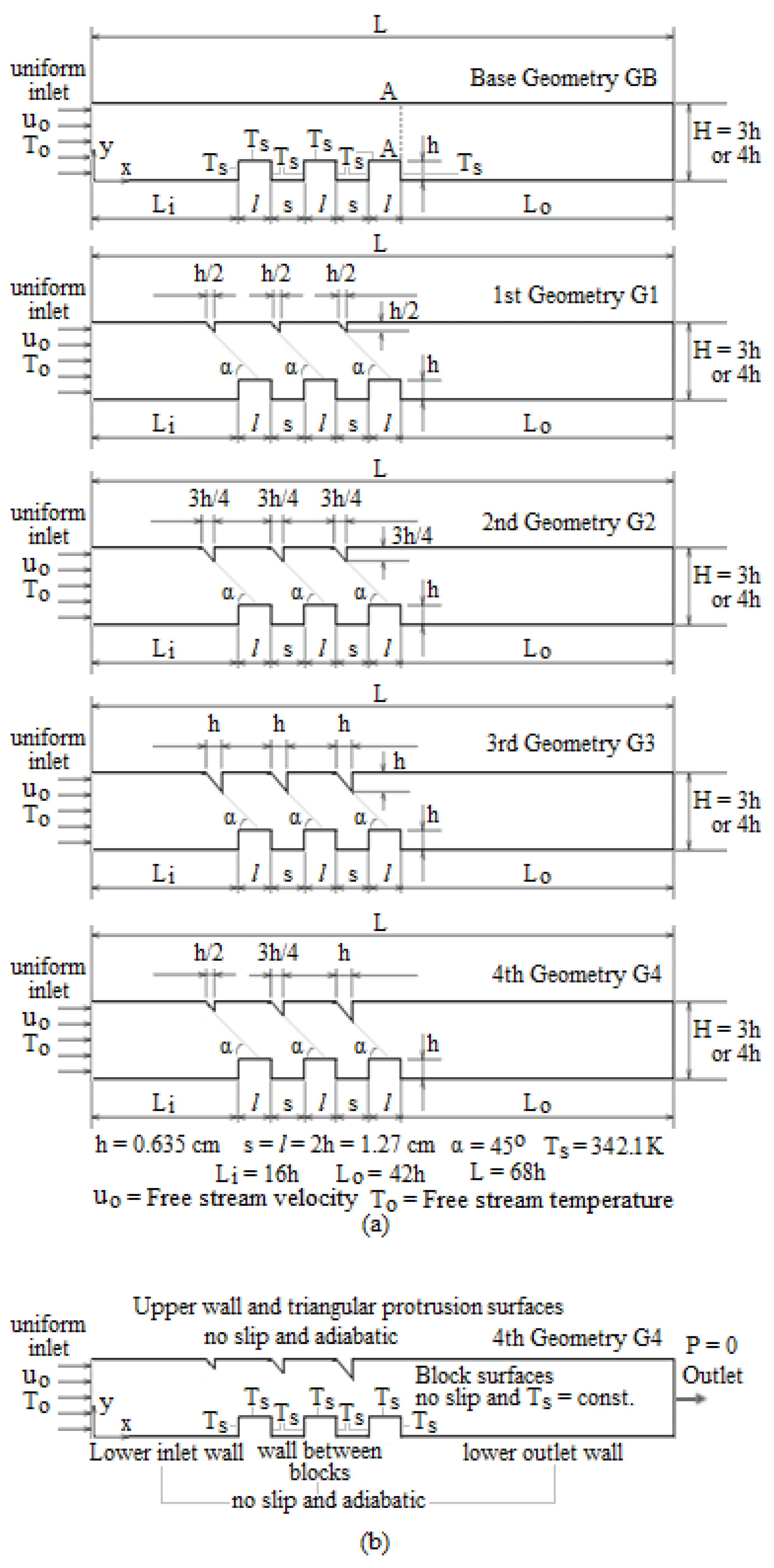
2.1. Geometrical Model, Computational Domain, and Boundary Conditions

Geometries are given for two different parallel plate channel heights (H = 3 h and H = 4 h) in Figure 1a. In the base case, only blocks are considered without protrusions mounted on the upper plate of the channel for comparison purposes. The number of heated elements and their dimensions of base geometry are inspired by Davalath and Beyazıtoglu [35], as these dimensional parameters are representative of the most common size on an integrated circuit (IC) component. Three different right-angled isosceles triangles are chosen as protrusions such that flow is directed to the middle of the upper surface of blocks to enhance heat transfer passively. Uniform inlet velocities corresponding to considered Reynolds numbers of 50, 200, and 500 are 0.03, 0.12, and 0.3 m/s, respectively, if Reynolds number is defined in terms of channel height of H = 4 h. Flow can be treated as laminar in the range of Reynolds number defined in terms of channel height between 100 and 1500 for air [35]. So, flow over the blocks is the laminar developing flow for considered Reynolds numbers, and outlet length Lo is sufficiently greater than inlet length Li to eliminate the outlet effect during numerical computations. Other geometrical factors that characterize simulated printed circuit board (PCB) passage are listed in Table 1 in comparison with similar geometrical factors in the literature. Thermophysical properties of air are considered as 20 °C and a constant surface temperature of Ts = 342.1 K is implemented on all block surfaces. In steady operating conditions of electronic components, it is reasonable to assume that each components reaches a constant temperature. So, there are many studies that assume constant surface temperature on the heated blocks simulates electronic components [27,36]. All other surfaces are adiabatic and pressure is taken as zero at the outlet of the channel. The computational domain and corresponding boundary conditions for the 4th Geometry G4 are shown in Figure 1b. All other geometries have similar boundary conditions.

2.2. Mathematical Model and Numerical Procedure

Flow is assumed as follows:
Laminar and incompressible: The Reynolds numbers were defined according to channel height as 37, 150, and 374 for H = 3 h, and 50, 200, and 500 for H = 4 h in this study, and in a similar Reynolds number range, the flow has been considered as laminar and incompressible in many studies [32,37,42,43,44,45]. Surface-mounted blocks cause a decrease in the cross-sectional area of passage and, simultaneously, the existence of protrusions in the upper wall also again decrease the cross-sectional area, resulting in an increase in inertial force in the direction flow, so the buoyancy effect is neglected. In the laminar study of Yu et al. [38], forced and mixed convection are compared for steady-state conditions in the Re number range of 200–800, and they concluded that the predicted maximum temperature rise in the chips may differ only 10 percent between mixed and forced convection modes. Viscous dissipation effects can also be neglected owing to the consideration of relatively small Re numbers resulting in less internal friction.
Two-dimensional and steady: If the only flow is considered in the centerline section of blocks, then it can be taken as two-dimensional. The transient response (time constant) of many electronic devices are can be treated as small, so flow is steady during the operating times.
The disadvantage of passive heat transfer enhancement using a rib, block, or fin is the negative effect of these protrusions on pressure loss. In practice, this causes an increase in fan power. However, pressure characteristics were not studied here. The results were presented for expansion ratios of 1.50 and 1.33 and block-height-based Reynolds numbers of 12, 50, and 125 (See Table 2). Governing equations for the conservation of mass, momentum, and energy can be written as follows [46]:
Continuity   equation :   u y + v y = 0
x - Momentum   equation :   u u x + v u y = 1 ρ P x + μ ρ ( 2 u x 2 + 2 u y 2 )
y - Momentum   equation :   u v x + v v y = 1 ρ P y + μ ρ ( 2 v x 2 + 2 v y 2 )
Energy   equation :   u T x + v T y = k ρ c p ( 2 T x 2 + 2 T y 2 )
The Galerkin finite element method of weighted residuals was used to discretize conservation equations. ANSYS-FLOTRAN uses the monotone streamline upwind method to discretize the advection terms. The weak form of the equation is established by taking the weighted average of the scalar equation over individual elements. The discretized equations are formed on an element basis and assembled into the global system. Conservation equations that include velocity and pressure were simultaneously solved with SIMPLEF algorithm developed by Schnipke and Rice [47]. Equations were solved iteratively and the tri-diagonal matrix algorithm (TDMA) method was used in the solution of the velocity field. Pressure and temperature fields were solved using the preconditioned conjugate gradient (PCCG) method. The convergence monitor is a normalized measure of the solution’s rate of change from iteration to iteration and iterations were terminated when the normalized rate of change was achieved as 1 × 10⁻² for velocity and 1 × 10⁻⁸ for pressure and temperature in this study. The same termination criteria were used in all computations including mesh independency and validation studies. A sample convergence monitor is given in Figure 2a for the case of 4th Geometry with H = 4 h and Uo = 0.3 m/s. There is a very small bulge on the left hand side of the temperature curve. Such bulges can often be encountered in iteration graphs of numerical solutions. If attention is paid, the height of this bulge is on the order of the magnitude of 10–9, that is, it is very small and negligible. Moreover, general numerical solution procedure is given in Figure 2b.

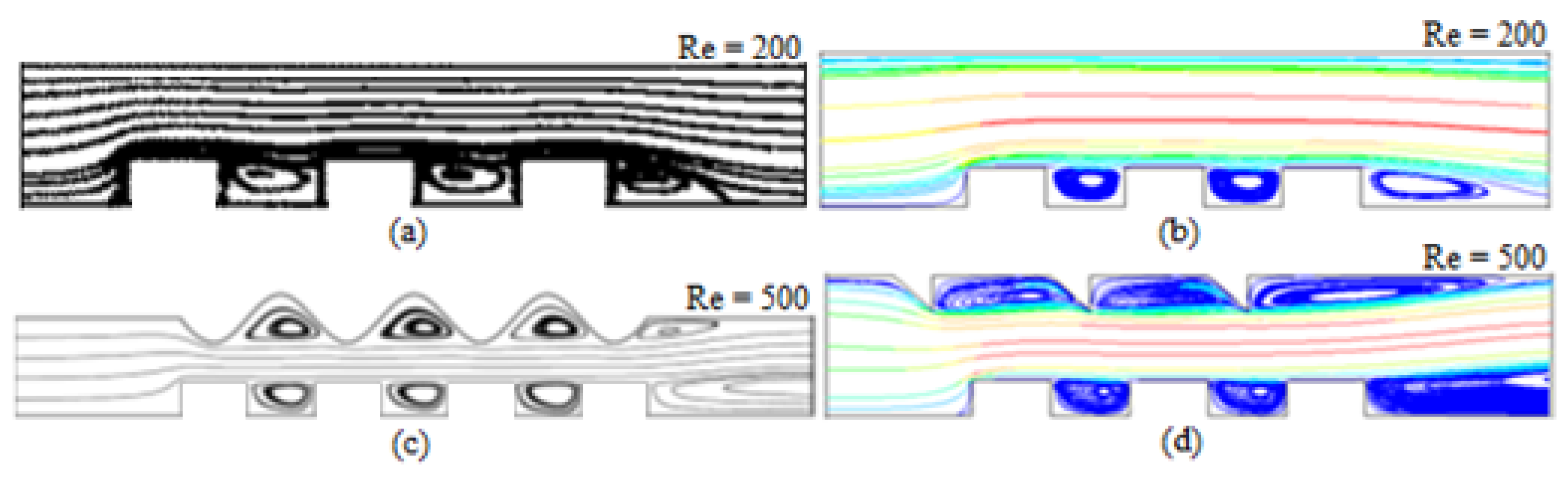
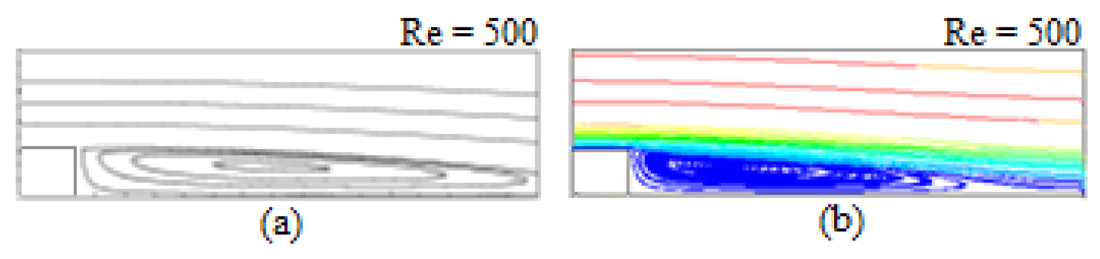
2.3. Mesh Independency and Validation Study

Structured quadratic meshes are used and, around blocks and protrusions, together with near walls, are meshed densely. A total thirty runs are performed for mesh independency studies of all considered geometries, as shown in Table 3. For all geometries and mesh structures in both passage heights, velocity profiles are drawn and compared at the section of AA in Figure 1. As an example, a comparison of velocity profiles for 3rd geometry with H = 3 h is given in Figure 3. A comparison of velocity profiles for all geometries was also performed and similar results were obtained. The difference between the maximum velocity at the section of AA for medium and coarse meshes is 4.49%, and this difference is decreased to 3.26% for fine and medium meshes. As seen from Figure 3, all mesh numbers satisfy mesh independency as there is a very small variation between the velocities for tested mesh numbers and fine meshes are used in all computations. The chosen mesh numbers for all geometries are also shown in bold in Table 3.
To validate the results, the experimental study of Nakamura and Igarashi [48] was modeled and solved using ANSYS-FLOTRAN R14.5 finite element code. Their study is related to forced convection heat transfer from a low-profile block placed in a rectangular duct, simulating heat transfer in a compact packaged electronic device. Measurements of local heat transfer from the block are performed by an infrared camera. The top surface of the low-profile block is subjected to a constant heat flux of 239 W/m2. All other details of the experimental setup and boundary conditions can be found in the study of Nakamura and Igarashi [48]. A comparison of predicted and measured local heat transfer coefficients of the top surface is given in Figure 4 for the considered case. A predicted curve is drawn for 4579 elements that are chosen as a result of the mesh independency study. As seen in Figure 4, predicted heat transfer coefficient values are very close to experimental ones.
Lastly, some streamline results of this study were compared qualitatively with similar studies including three surface mounted blocks in the literature, as seen in Figure 5 and Figure 6. Although the boundary conditions are not identical to those of the compared studies, very similar and satisfactory streamlines patterns were obtained in this study. In Figure 5a,b, Reynolds-number-defined block length and block height in both studies are respectively converted into Reynolds-number-defined channel height to achieve a meaningful comparison.

3. Results and Discussion

3.1. Fluid Flow Characteristics

The results are obtained from three different inlet velocities (Uo = 0.03, 0.12, and 0.3 m/s) and two different channel heights (H = 3 h and 4 h). As constant velocity fans are used generally in the air cooling of printed circuit boards, it is reasonable to consider the constant inlet velocity for each channel height. The gap height (H–h) between the blocks and the opposite wall of the channel is considered the main flow passage, so attention is focused on the calculation of the Reynolds number [50,51]. If the Reynolds number is defined according to channel height H or hydraulic diameter Dh, there will be two different Reynolds numbers with two different channel heights or hydraulic diameters for the same inlet velocity. So, it cannot be understood very well whether the heat transfer increase is due to an increase in mass flow rate or an increase in Re number. Or there will be two different inlet velocities with two different channel heights for a fixed Re number. This situation has been also discussed in detail by Tang and Ghajar [52], and they have chosen the characteristic length as the height of the block. If channel height is changed by changing block height (h) instead of the gap height, the Reynolds number will not change for channel height or hydraulic diameter. Possible Reynolds numbers according to possible characteristic lengths are summarized in Table 2. In some studies, the Reynolds number is defined in terms of block height of h [52,53,54,55,56], but it should be noted that these studies are studies in which buoyancy is taken into account. In some other studies, the characteristic length in the definition of the Reynolds number has been chosen as the length of the block [39,57,58] or the gap height [50]. Chen et al. [59] have investigated the effects of step height for turbulent separated convection flow adjacent to backward facing step by considering constant inlet velocity by changing (H–h). In this study, the Reynolds number was defined in terms of channel height as follows:
Re = u o H υ
and the corresponding Reynolds numbers are 37, 150, and 374 for H = 3 h, and 50, 200, 500 for H = 4 h.

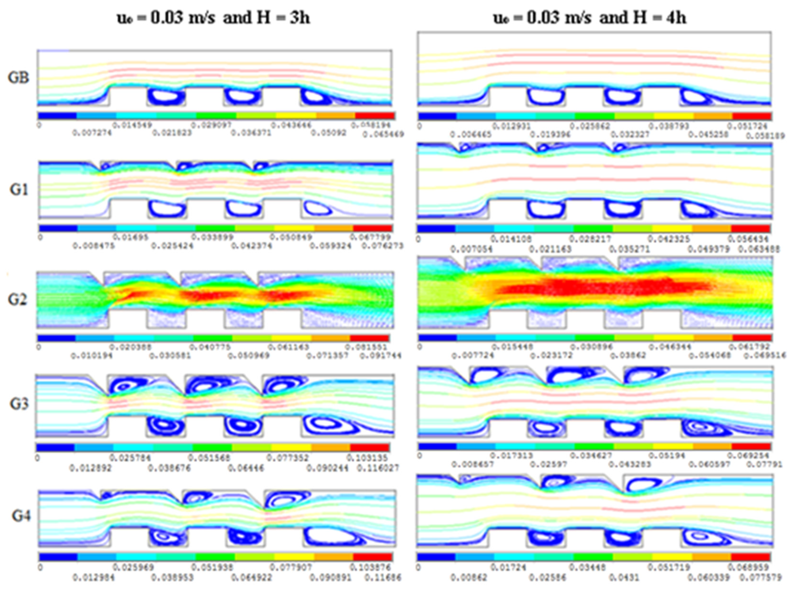
3.2. Effects of Channel Height on Flow Structures

Streamline patterns and some velocity vectors are given for two different channel heights by fitting the inlet velocity constant in Figure 7, Figure 8 and Figure 9 for the complete (middle) domain. For comparison purposes, velocity vectors together with streamlines are given only for the G2 case of Uo = 0.03 m/s in Figure 7. In addition, velocity magnitude and direction in vector plots can be seen more easily than streamline plots. AS expected, the existence of protrusions completely changes the flow patterns on the upper wall. If the size of the protrusions is increased, the existence of protrusions starts to affect the flow patterns on the lower wall. The effect of different sized protrusions case downstream of the geometry in the case of G4 is almost the same as the case of G3. Therefore it can be said that the size of the last protrusion controls the flow structure downstream of the last block. The flow between blocks is similar to cavity flow and it seems that the flow structure does not affect front of the first blocks and between blocks. Only a single clockwise (cc) vortex is formed between blocks, and the upper right tips of the vortex are pressed downward by impinging effect of the flow directed from protrusions to the blocks. Normally, this effect is minimum for the base case because there is no protrusion on the upper wall. This effect disappears with an increasing Reynolds number because inertial force towards the forward direction increases with the increasing velocity by damping this impinging effect. On the upper wall, only a single counterclockwise (ccw) vortex between protrusions is formed, and the length of the vortex increases with the increasing size of protrusions. The effect of protrusions’ size on vortex length can be seen clearly in the case of different sized protrusions (i.e., case G4) and, from left to right, the length of the vortex increases with the increasing the size of protrusion. Again, because of the effect of the different sized protrusions downstream of the last protrusion in the case of G4 is also almost the same as in the case of G3, it can be said that the last protrusion controls the flow structure downstream of the last protrusion on the upper wall, similar to the lower wall case. That is, the last protrusion plays an important role in the flow structure for both lower and upper walls. It seems that the main effect of channel height is on the velocity of core flow between blocks and protrusions. For lower channel height (H = 3 h), the velocity of core flow decreases on the cavities between blocks because protrusions direct the flow towards the blocks. For a higher channel height (H = 4 h), there is nearly no distortion of streamlines in core flow. These distortion effects together with a decrease in velocity are much for protrusions with different dimensions (case of G4). As mentioned by Alawadhi [32], fluid flow, including the speed of the axial core flow and the recirculating flow between the blocks, plays an important role in transporting thermal energy out of the blocks.
As seen from Figure 10, Figure 11 and Figure 12, at the downstream, the flow is separated from the last block to form a recirculating flow in addition to separation from the last protrusion in the upper wall. Downstream flow is similar to flow around the backward-facing step, and this representative separation flow model has been studied comprehensively [60]. If channel height changes, the expansion ratio also changes and the expansion ratio decreases with the increasing channel height, as seen in Table 1. Separated flow reattaches at a certain distance called the reattachment length (RL), and the reattachment length is a function of the Reynolds number and the expansion ratio (ER) [61]. The reattachment length is estimated by finding the zero wall shear stress position, and the effects of the expansion ratio and Re number on reattachment length are given in Figure 13. For a fixed inlet velocity, as the Re number slightly increases, the effect of the expansion ratio on reattachment length is nearly negligible, as seen from Figure 10, Figure 11 and Figure 12 for GB (base geometry). For the inlet velocity of 0.03 m/s (Re = 37 and 50), reattachment length very slightly increases with the decreasing expansion ratio. For the inlet velocity of 0.15 m/s (Re = 150 and 200), reattachment lengths are almost the same for both expansion ratios, but at this inlet velocity reattachment length starts to decrease, and reattachment length slightly decreases with decreasing expansion ratio for the inlet velocity of 0.30 m/s (Re = 374 and 500). In the literature, related to the effects of expansion ratio on reattachment length, there are opposite arguments among the researchers. For example, Thangam and Knight [61] have concluded that reattachment length increases with the increasing expansion ratio for a fixed Re number defined in terms of hydraulic diameter, which is equal to twice the height of the channel inlet, Dh = 2 H (so, if the height of the channel inlet is changed, then inlet velocity changes). In this way, at a given Re number, an increase in the velocity at the channel inlet occurs, thereby causing an increase in the reattachment length. In this study, as mentioned above, the effect of the expansion ratio on reattachment length is negligible because inlet velocity does not change at the channel inlet, as seen from boundary conditions. In the study of Thangam and Knight [61], results were presented for the Re number range of 50–900 and expansion ratios from 0.25 to 0.75. Whereas the opposite argument has been mentioned by Kitoh et al. [56], that is, the reattachment length increases with the decreasing expansion ratio for a fixed Re number defined in terms of step height. The results were presented for an Re number range of 300–1000 and expansion ratio range of 1.5–3.0 in their study. In addition to the laminar case, similar inverse results are available in the case of turbulent flow, as reported by Kitoh et al. [56]. As mentioned by these researchers, further investigation is needed. For cases with protrusions, that is, G1, G2, G3, and G4, reattachment lengths downstream of the last block and last protrusion are also estimated by the same method, and almost similar results with the base case as seen from Figure 13 are obtained. However, there are some changes in flow structures with increasing sizes of protrusions as seen in Figure 10, Figure 11 and Figure 12. For the lower channel height case (H = 3 h and higher expansion ratio), velocity loses its intensity in a shorter distance than the higher channel height case (H = 4 h and lower expansion ratio). The existence of protrusions on the upper wall decreases the intensity of the velocity in the core region, and this decrease continues with an increasing dimension of protrusions. After the G1 case, velocity vectors in the core region tend to move in an upward direction slightly. This tendency is at a maximum for the case of G3 with the largest protrusions. The almost same maximum tendency was observed for the case of G4. The last protrusion has the maximum effect on the downstream flow region. The upper recirculation region (secondary recirculation) downstream of the last protrusion starts to appear from the case of G2 (it appears in white color). Moreover, the secondary recirculation region on the upper wall starts to appear from the case of G3 for the inlet velocity of 0.12 m/s (Re = 150 and 200) and from the case of G2 for the inlet velocity of 0.30 m/s (Re = 374 and 500). Secondary circulation regions appear only for a smaller channel height of H = 3 h with a higher expansion ratio of 1.50, consistent with the study of Thangam and Knight [61].

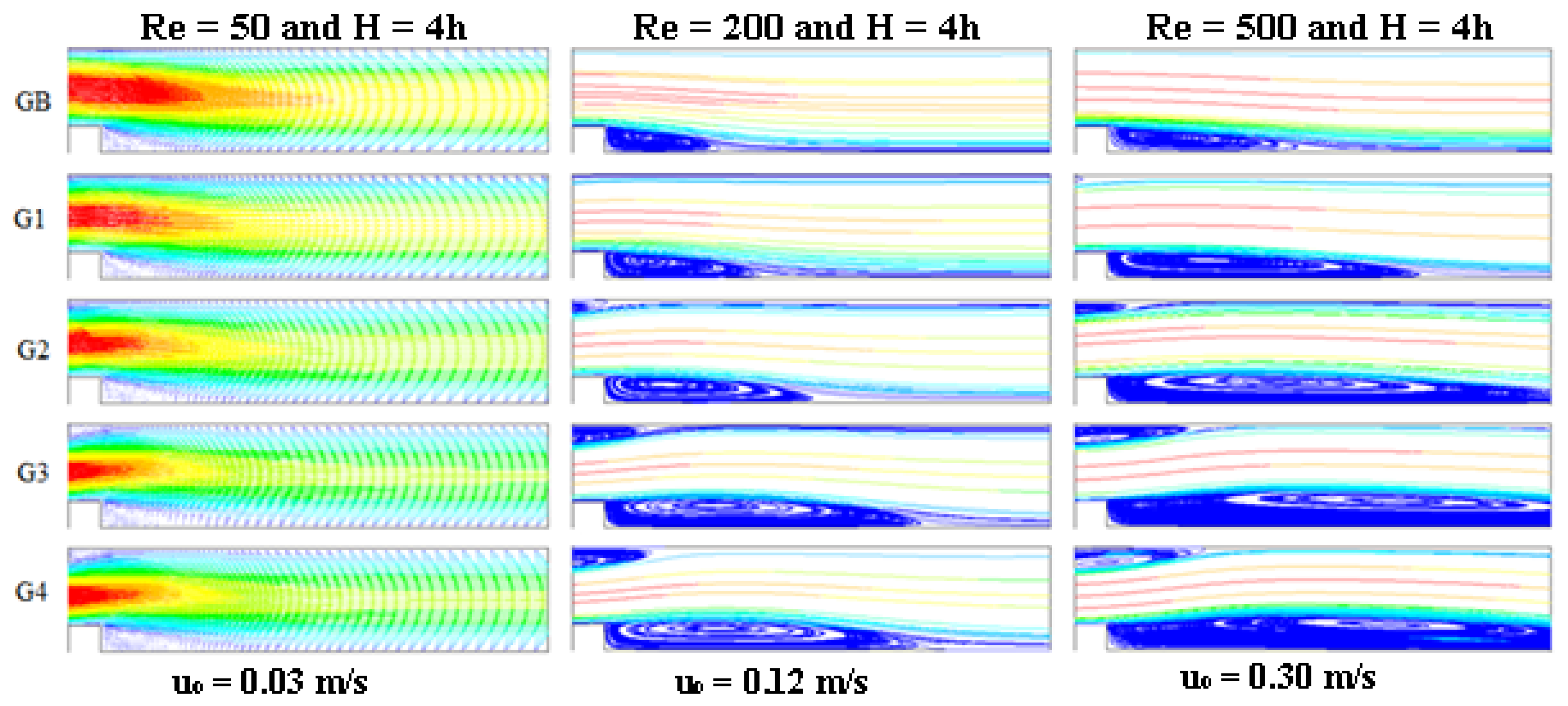
3.3. Effects of Inlet Velocity (Reynolds Number) on Flow Structures

Streamline patterns and sometimes velocity vectors are given for three different Reynolds numbers by fitting the channel height constant in Figure 14 and Figure 15 for the complete (middle) domain. For comparison purposes, velocity vectors together with streamlines are given only for case G2 in the inlet velocity of 0.03 m/s (Re = 37 and 50). In addition, the velocity magnitude and direction in vector plots can be seen more easily than streamline plots. The center of a vortex between blocks shifts to the right for increasing Reynolds number for a constant channel height, as seen in Figure 14 and Figure 15, and this finding is consistent with the study of Davalath and Bayazitoglu [35]. Moreover, there is no recirculation zone ahead of the first block for the considered Reynolds number range for all cases. A similar finding was reported by Davalath and Bayazitoglu [35] only for cases without protrusions in the Reynolds number range of 100 to 1500. On the upper wall, after the last protrusion, another recirculation is formed and the length of the recirculation increases with the increasing Re number, as seen in Figure 14 and Figure 15. Velocity vectors for the inlet velocity of 0.03 m/s (Re = 37 and 50) and streamline patterns for the inlet velocity of 0.12 m/s (Re = 150 and 200) and the inlet velocity of 0.30 m/s (Re = 374 and 500) 125 are given for three different inlet velocities by fitting the channel height constant in Figure 16 and Figure 17 for the downstream region after the last block. At first sight, it can be seen that the reattachment length increases with the increasing Reynolds number for a fixed expansion ratio. This phenomenon may be explained by noting that, at a given expansion ratio, an increase in the Reynolds number of the inlet is accompanied by an increase in the inertial forces, and this leads to an increase in the reattachment length [56]. As mentioned by Malamataris and Löhner [43] secondary eddy for backward-facing step flow with the fixed expansion ratio of 1.94 appears for Re ˃ 400 in two-dimensional laminar regime computations [62] and experiments [63]. In this study, this secondary eddy was not detected for a smaller expansion ratio of 1.33 (H = 4 h), although the Re number is greater than 400, as seen in Figure 17 (In this Figure, Re = 500). So, the expansion ratio and inflow conditions caused by blocks and protrusions have a great influence on the formation of secondary recirculation in addition to Reynolds number. As seen from Figure 16, the tendency of flow towards the upper wall in the cases of G3 and G4 for Re = 150 possibly causes this secondary recirculation because impinging fluid to the upper wall reflects downward after impingement. For a higher Reynolds number (Re = 374), this secondary eddy approaches the outlet owing to higher inertial force resulting in a velocity increase. The Lattice Boltzmann simulation study of Moussaoui et al. [36] considered one block in the lower wall and two blocks of the upper wall. In their study, if the upper block is located just above the lower block (that is, not before or not after the lower block), they mentioned that the recirculation formed downstream of the upper block (secondary eddy) is larger than the lower one. In this study, the upper protrusion is not a square, it is a triangle, and the secondary eddy (that is, recirculation formed downstream the last upper triangular protrusion) is smaller than the primary eddy (that is, recirculation formed downstream of the last block mounted on the lower wall) in all cases except the base case (GB). This impingement effect has not have any influence on the formation of secondary recirculation for a smaller expansion ratio of 1.33.

3.4. Heat Transfer Characteristics

The convective heat transfer coefficient is expressed by Newton’s law of cooling as follows [46]:
h   = q ( T T s )
where q and Ts are local heat flux and surface temperature, respectively. The local heat flux q is obtained by applying Fourier’s law to the fluid at the first mesh layer (or interface) adjacent to the block surface:
q   = -   k Δ T Δ y
where k is the conductivity of the air. The average heat transfer coefficient over the entire block can be obtained by taking the arithmetical mean of the local heat transfer coefficients computed for each grid point at the first mesh layer adjacent to the block surface. Then, the average heat transfer coefficient over the entire PCB can be determined from
h a v e = 1 3 1 3 h n
where hn is the average heat transfer coefficient of the nth block. Representative local heat transfer coefficient distributions for all geometries are given in Figure 18a for H = 3 h and Re = 37 and Figure 18b for H = 4 h and Re = 50. As seen from these figures, local heat transfer coefficients increase with the decreasing channel height. This increase can be attributed to the velocity increase above the blocks owing to a decrease in gap height that causes a decrease in cross-sectional area. The maximum local heat transfer coefficient for each block occurs at the front corner and the minimum value occurs in the cavity between the two blocks. The first block has a much larger heat transfer coefficient value along its left surface than the second block owing to the impact of the core flow as it is redirected into the bypass region. As seen in Figure 7, the streamline curvature becomes very large locally at the front corner, having a high velocity, and the convective heat transfer coefficient is large. This situation can be attributed to a secondary boundary layer beginning at the leading edge of the top surface. The thermal boundary layer at this point is the thinnest and, therefore, the local heat transfer coefficient is the highest. Another interesting point is in the increase in the heat transfer coefficient around the upper right corners of the blocks, which agrees well with the findings in Karichi and Oufer 2005 [30], Chen and Wong 1988 [64], Igarashi and Takasaki 1995 [65], Young and Vafai 1998 [65,66], Wu et al. 1998 [27], and Leung et al. 2000 [67]. Although there is a slight increase, especially in the studies of Young and Vafai 1998 [66], Leung et al. 2000 [67], and Karichi and Oufer 2005 [30], there is a sharp increase in this study consistent with the findings of Chen and Wong 1988 [64] and Wu et al., 1998 [27]. This effect is due to the surface temperature decreasing near the corner where downstream the fluid is not being further heated by the wall (Young and Vafai 1998 [66] and Leung et al., 2000 [67]). However, it must be noted that constant heat flux was applied in both studies. In this study, the constant surface temperature was considered and this phenomenon can be attributed to a decrease in heat flux at the surface near the corner where, downstream, the fluid is not being further heated by the wall, similar to the constant heat flux case. This effect was also explained by an increase in turbulence intensity in the study of Igarashi and Takasaki 1995 [65]. Poor heat transfer occurs between the blocks owing to the recirculation zone. The heat transfer between the right face of the block and the left face of the preceding block is dominated by the cavity vortices. The local heat transfer coefficient shows almost the same characteristic behavior for all geometries channel heights except for the higher inlet velocity of 0.30 m/s. As seen from Figure 19, just after the first corner of the first block, the heat transfer coefficient decreases sharply and then increases again, especially for H = 3 h and 0.30 m/s. This effect is explained as the attachment of the main flow at the top surface of the first block; Meinders et al. (1998) [68]. Although peak values of the heat transfer coefficients at the front corners of the blocks decrease from the first block to the second and third ones gradually, the peak value of the heat transfer coefficient at the rear corner of the second block is less than the first block’s rear corner, but the heat transfer coefficient at the rear corner of the third block is almost the same order of magnitude as the second one. The existence of triangular protrusions does not change the characteristic behavior of the heat transfer coefficient curves for all geometries, but the order of the curves for different geometries changes in the second and third blocks. For the cases of G1, G2, and G3, the heat transfer coefficient increases with an increasing dimension of triangular protrusions. For the first block, the heat transfer coefficient increases with the increasing size of triangular protrusions. In the case of G4, the heat transfer coefficient curve for the first block is similar to the case of G2 and has the smallest size of the triangular protrusions. That is, in the first block, the dimension of the first protrusion controls the local heat transfer distribution, and there is no influence of the dimensions of the second and third blocks on the local heat transfer distribution.
In Figure 20, the average heat transfer coefficients of blocks for all geometries and the same inlet velocity of 0.3 m/s are given for H = 3 h (a) and H = 4 h (b). The average heat transfer coefficient curves of blocks are not given for other inlet velocities because similar trends are obtained. For both channel heights, heat transfer increases with the increasing size of triangular protrusions; in this way, the maximum increase in heat transfer occurs in G3. This increase is prominent, especially for the first block. The order of increase diminishes with the increasing channel height. In addition, in the second block, there is almost no difference between the base case and cases with protrusions for H = 4 h. The increase rates in the average heat transfer coefficient for H = 3 h are 49.99%, 48.25%, and 33.92% for the first, second, and third blocks respectively. Similarly, the increase rates in the average heat transfer coefficient for H = 4 h are 32.74%, 3.23%, and 22.26% for the first, second, and third blocks respectively. The much lower increase rate in the average heat transfer coefficient of the second block than the third block for H = 4 h in contrast with H = 3 h is interesting, and this situation is also encountered in the study of Chen et al., 2001 [41], but the decrease in the increase rate is not lower than in this study. Although the average heat transfer coefficient curves of blocks exhibit similar trends for 0.03 m/s and 0.12 m/s with 0.30 m/s, the increase rates in the average heat transfer coefficients of the second blocks in the small channel height of H = 3 h for the inlet velocities of 0.03 m/s and 0.12 m/s are greater than for the case of 0.30 m/s. In addition, it seems that the inertia of the main flow between the tips of the blocks and the protrusions prevents the direction of the flow towards the upper surfaces of the blocks, which results no increase in heat transfer owing to the impingement effect in the blocks for both channel heights, in spite of a significant heat transfer increase in the blocks. So, a heat transfer increase due to protrusions is provided by a velocity increase because of the gap decrease. To compare average heat transfer values of the blocks with similar numerical [39] and experimental [41] studies in the literature, block-height-based average Nusselt numbers of the Base Geometry were calculated and are given in Figure 20c. A similar trend in the Nuave curves is obtained for the same or similar Re number, and discrepancies are possibly due to different boundary conditions and geometrical parameters in the compared numerical [39] and experimental [41] studies.
In Figure 21, the overall average heat transfer coefficients of all geometries are given for H = 3 h and H = 4 h. For all geometries and inlet velocities, average heat transfer coefficients of all geometries for the channel height of H = 3 h are higher than the channel height of H = 4 h. Average heat transfer coefficient increases with the increasing size of geometries for both channel heights. For the channel height of H = 3 h, the slope of the average heat transfer coefficient is constant from Base Geometry (GB) to G3 and decreases from G3 to G4. The average heat transfer coefficient of geometry that has mixed sized protrusions (G4) is almost the same as the geometry of G2. So, heat transfer is controlled by the first small sized protrusion in the mixed sized protrusions of G4. For the channel height of H = 4 h, the slope of the average heat transfer coefficient slightly decreases after G2 to G3. Then, the average heat transfer coefficient slowly decreases to the value of G4 in comparison with H = 3 h. As a result, maximum heat transfer enhancement is provided with the geometry of G3, which has maximum sized protrusions. For this geometry, the maximum increase rates in the average heat transfer coefficient for H = 3 h are 26.66%, 35.42%, and 47.17% for the inlet velocities of 0.03 m/s, 0.12 m/s, and 0.3 m/s, respectively. Similarly, the maximum increase rates of average heat transfer coefficient for H = 4 h are 13.58%, 17.90%, and 24.21% for the inlet velocities of 0.03 m/s, 0.12 m/s, and 0.3 m/s, respectively.
An understanding of flow characteristics before the thermal design of printed circuit board passages with triangular guide protrusions can help researchers and designers in the electronics cooling community to enhance heat transfer passively by reducing cooling costs.

4. Conclusions and Future Work

Two-dimensional, incompressible, steady, and laminar flow analysis was performed to predict fluid flow characteristics for possible heat transfer enhancement purposes from three heated blocks in a printed circuit board passage with triangular guide protrusions mounted on the upper wall. There is no study that investigates triangular guide protrusions including their systematical geometrical changes together with the effects of channel height in the open literature in the context of the authors’ knowledge. Moreover, the number of laminar studies is less than turbulent studies, whereas low velocity or natural convection cases are still important, especially for small devices in small PCB passages.
As expected, the existence of protrusions completely changes the flow patterns on the upper wall. If the size of the protrusions is increased, the existence of protrusions starts to affect the flow patterns on the lower wall.
The size of the last protrusion controls the flow structure both downstream of the last block and the last protrusion.
Reattachment length is a function of the Reynolds number and the expansion ratio. For a fixed inlet velocity, the effect of the expansion ratio on reattachment length is nearly negligible for the base case of GB. For the inlet velocity of 0.03 m/s (Re = 37 and 50), reattachment length very slightly increases with the decreasing expansion ratio. For the inlet velocity of 0.12 m/s (Re = 150 and 200), reattachment lengths are almost the same for both expansion ratios, but at this inlet velocity, reattachment length starts to decrease, and reattachment length slightly decreases with decreasing expansion ratio for the inlet velocity of 0.30 m/s (Re = 374 and 500). Similar but slightly different results are obtained for all other geometries. In the literature, the effect of expansion ratio on reattachment length is not clear, possibly because of the characteristic length definition, and further investigation is needed.
For a fixed expansion ratio, reattachment length increases with the increasing inlet velocity (Reynolds number) for all cases.
The upper recirculation region (secondary recirculation region) on the upper wall starts to appear from the case of G3 for the inlet velocity of 0.12 m/s (Re = 150 and 200) and from the case of G2 for the inlet velocity of 0.30 m/s (Re = 374 and 500). Secondary circulation regions appear only for a smaller channel height of H = 3 h with a higher expansion ratio of 1.50, consistent with the literature. This secondary eddy was not detected for the inlet velocity of 0.03 m/s (Re = 37 and 50) of a higher expansion ratio of 1.50, and for a smaller expansion ratio of 1.33. Expansion ratio and inflow conditions caused by blocks and protrusions have a great influence on the formation of secondary recirculation in addition to the Reynolds number.
Local heat transfer coefficient distribution increases with increasing sizes of upper triangular protrusions, and the maximum heat transfer coefficient distribution is obtained in G3. However, this increase decreases with the increasing channel height. Local heat transfer coefficient distribution increases with the increasing inlet velocity for a fixed geometry.
The average heat transfer coefficients of blocks also increase with increasing sizes of upper triangular protrusions. Maximum heat transfer enhancement is provided with the geometry of G3 and the lower channel height. Important increase rates are obtained for the second and third blocks, except for the second block of H = 4 h.
Similarly, average heat transfer coefficients of geometries increase with the increasing sizes of upper triangular protrusions. Maximum heat transfer enhancement is also provided with the geometry of G3, which has maximum sized protrusions. Mixed sized triangular protrusions have no significant effect on heat transfer enhancement, but have a significant effect on the downstream flow structure.
It has been expected that fluid flow, including the speed of the axial core flow and the recirculating flow between the blocks, plays an important role in transporting thermal energy out of the blocks. So, three-dimensional fluid flow and heat transfer analysis may result in more accurate results in future work.

Author Contributions

Conceptualization, E.P.; methodology, E.B., B.E.Y., M.A. and E.P.; software, E.B., B.E.Y. and K.F.S.; validation, E.P.; formal analysis, R.Y.; investigation, E.P. and M.A.; resources, E.B., B.E.Y., M.A. and K.F.S.; data curation, E.P. and K.F.S.; writing—original draft preparation, R.Y.; writing—review and editing, R.Y. and E.P.; visualization, R.Y.; supervision, E.P. All authors have read and agreed to the published version of the manuscript.

Funding

This research received no external funding.

Institutional Review Board Statement

Not applicable.

Informed Consent Statement

Not applicable.

Data Availability Statement

Not applicable.

Acknowledgments

The last author acknowledges his undergraduate project students of S. Köksal, G. Bütün, and I. Inan for their valuable assistance during numerical computations.

Conflicts of Interest

The authors declare no conflict of interest.

Nomenclature

cpconstant pressure specific heat, J/kgK
Dhhydraulic diameter of the channel, m
ERexpansion ratio
Hchannel height, m
hstep height or heat transfer coefficient, m or W/m2K
ICintegrated circuit
kthermal conductivity, W/mK
Lchannel length, m
lblock length, m
NuNusselt number
Ppressure, Pa
PCBPrinted circuit board
ReReynolds number
RLreattachment length, m
sdistance between blocks, m
Ttemperature, °C or K
ux-component of velocity, m/s
xaxial distance, m
vy-component of velocity, m/s
yvertical distance, m
Greek symbols
αincident angle of fluid from protrusions to upper surface of blocks, °
ρdensity, kg/m3
νkinematic viscosity, m2/s
Subscript
aveaverage
iinlet
nfor the nth block
ofree stream or outlet
ssurface

References

  1. Hannemann, R. Thermal control for mini- and microcomputers: The limits of air cooling. Bull. Int. Cent. Heat Mass Transf. 1989, 3, 65–83. [Google Scholar]
  2. Bergles, A.E. Evolution of cooling technology for electrical, electronic, and microelectronic equipment. Heat Transf. Eng. 1986, 7, 97–105. [Google Scholar] [CrossRef]
  3. Sathe, S.; Sammakia, B. A review of recent developments in some practical aspects of air-cooled electronic packages. ASME J. Heat Transf. 1998, 120, 830–839. [Google Scholar] [CrossRef]
  4. Kim, S.J.; Kim, D. Forced convection in microstructures for electronic equipment cooling. ASME J. Heat Transf. 1999, 121, 639–645. [Google Scholar] [CrossRef]
  5. Webb, R.L. Next generation devices for electronic cooling with heat rejection to air. ASME J. Heat Transf. 2005, 127, 2–10. [Google Scholar] [CrossRef]
  6. Guo, Z.Y.; Li, D.Y.; Wang, B.X. A novel concept for convective heat transfer enhancement. Int. J. Heat Mass Transf. 1998, 41, 2221–2225. [Google Scholar] [CrossRef]
  7. Bergles, A.E. Recent developments in enhanced heat transfer. Heat Mass Transf. 2011, 47, 1001–1008. [Google Scholar] [CrossRef]
  8. Christensen, A.; Graham, S. Thermal Effects in Packaging High Power Light Emitting Diode Arrays. Appl. Therm. Eng. 2009, 29, 364–371. [Google Scholar] [CrossRef]
  9. Culham, J.R.; Khan, W.A.; Yovanovich, M.M.; Muzychka, Y.S. The Influence of Material Properties and Spreading Resistance in the Thermal Design of Plate Fin Heat Sinks. Trans. ASME J. Electron. Packag. 2007, 129, 76–81. [Google Scholar] [CrossRef]
  10. Almuhtady, A.; Alhazmi, M.; Al-Kouz, W.; Raizah, Z.A.S.; Ahmed, S.E. Entropy Generation and MHD Convection within an Inclined Trapezoidal Heated by Triangular Fin and Filled by a Variable Porous Media. Appl. Sci. 2021, 11, 1951. [Google Scholar] [CrossRef]
  11. Das, R. A Simplex Search Method for a Conductive-Convective Fin with Variable Conductivity. Int. J. Heat Mass Transf. 2011, 54, 5001–5009. [Google Scholar] [CrossRef]
  12. Mallick, A.; Das, R. Application of Simplex Search Method for Predicting Unknown Parameters in an Annular Fin Subjected to Thermal Stresses. J. Therm. Stress. 2014, 37, 236–251. [Google Scholar] [CrossRef]
  13. Deshamukhya, T.; Bhanja, D.; Nath, S. Heat Transfer Enhancement Through Porous Fins: A Comprehensive Review of Recent Developments and Innovations. Proc. Inst. Mech. Eng. Part C J. Mech. Eng. Sci. 2021, 235, 946–960. [Google Scholar] [CrossRef]
  14. Karabulut, K. Heat Transfer Improvement Study of Electronic Component Surfaces Using Air Jet Impingement. J. Comput. Electron. 2019, 18, 1259–1271. [Google Scholar] [CrossRef]
  15. Karabulut, K.; Alnak, D.E. Study of Cooling of the Varied Designed Warmed Surfaces with and Air Jet Impingement. Pamukkale Univ. J. Eng. Sci. 2020, 26, 88–98. [Google Scholar] [CrossRef] [Green Version]
  16. Takeishi, K.-I.; Krewinkel, R.; Oda, Y.; Ichikawa, Y. Heat Transfer Enhancement of Impingement Cooling by Adopting Circular-Ribs or Vortex Generators in the Wall Jet Region of a Round Impingement Jet. Int. J. Turbomach. Propuls. Power 2020, 5, 17. [Google Scholar] [CrossRef]
  17. Ren, Z.; Yang, X.; Lu, X.; Li, X.; Ren, J. Experimental Investigation of Micro Cooling Units on Impingement Jet Array Flow Pressure Loss and Heat Transfer Characteristics. Energies 2021, 14, 4757. [Google Scholar] [CrossRef]
  18. Alnak, D.E.; Koca, F.; Alnak, Y.A. Numerical Investigation of Heat Transfer from Heated Surfaces of Different Shapes. J. Eng. Thermophys. 2021, 30, 494–507. [Google Scholar] [CrossRef]
  19. Koca, F. Numerical Investigation of Corrugated Channel with Backward-Facing Step in Terms of Fluid Flow and Heat Transfer. J. Eng. Thermophys. 2022, 31, 187–199. [Google Scholar] [CrossRef]
  20. Nazir, U.; Sohail, M.; Selim, M.M.; Alrabaiah, H.; Kumam, P. Finite Element Simulations of Hybrid Nano-Carreau Yasuda Fluid with Hall and Ion Slip Forces over Rotating Heated Porous Cone. Sci. Rep. 2021, 11, 19604. [Google Scholar] [CrossRef]
  21. Naseem, T.; Nazir, U.; Sohail, M.; Alrabaiah, H.; Sherif, E.-S.M.; Park, C. Numerical exploration of thermal transport in water-based nanoparticles: A computational strategy. Case Stud. Therm. Eng. 2021, 27, 101334. [Google Scholar] [CrossRef]
  22. Wang, F.; Nazir, U.; Sohail, M.; El-Zahar, E.R.; Park, C.; Thounthong, P. A Galerkin Strategy for Tri-Hybridized Mixture in Ethylene Glycol Comprising Variable Diffusion and Thermal Conductivity Using Non-Fourier’s Theory. Nanotechnol. Rev. 2022, 11, 834–845. [Google Scholar] [CrossRef]
  23. Algehyne, E.A.; El-Zahar, E.R.; Elhag, S.H.; Bayones, F.S.; Nazir, U.; Sohail, M.; Kumam, P. Investigation of Thermal Performance of Maxwell Hybrid Nanofuid Boundary Value Problem in Vertical Porous Surface via Finite Element Approach. Sci. Rep. 2022, 12, 2335. [Google Scholar] [CrossRef] [PubMed]
  24. Medjahed, D.M.; Ameur, H.; Rebhi, R.; Inc, M.; Ahmad, H.; Menni, Y.; Lorenzini, G.; Bayones, F.S.; Aldhabani, M. Details on the Hydrothermal Characteristics within a Solar-Channel Heat-Exchanger Provided with Staggered T-Shaped Baffles. Energies 2021, 14, 6698. [Google Scholar] [CrossRef]
  25. Zargar, A.; Tarokh, A.; Hemmati, A. The Steady Wake of a Wall-Mounted Rectangular Prism with a Large-Depth-Ratio at Low Reynolds Numbers. Energies 2021, 14, 3579. [Google Scholar] [CrossRef]
  26. Myrum, T.A.; Acharya, S.; Sinha, S.; Qui, X. The effect of placing vortex generators above ribs in ribbed ducts on the flow, flow temperature, and heat transfer behavior. ASME J. Heat Transf. 1996, 118, 294–300. [Google Scholar] [CrossRef]
  27. Wu, H.-W.; Wang, S.-W.; Perng, S.-W. The effective installation of an inclined plate for the enhancement of forced convection over rectangular sources. Heat Mass Transf. 1998, 33, 431–438. [Google Scholar] [CrossRef]
  28. Yoo, S.-Y.; Park, J.-H.; Chung, M.-H. Local heat transfer characteristics in simulated electronic modules. ASME J. Electron. Packag. 2003, 125, 362–368. [Google Scholar] [CrossRef]
  29. Fu, W.-S.; Tong, B.-H. Numerical investigation of heat transfer characteristics of the heated blocs in the channel with a transversely oscillating cylinder. Int. J. Heat Mass Transf. 2004, 47, 341–351. [Google Scholar] [CrossRef]
  30. Korichi, A.; Oufer, L. Numerical heat transfer in a rectangular channel with mounted obstacles on upper and lower walls. Int. J. Therm. Sci. 2005, 44, 644–655. [Google Scholar] [CrossRef]
  31. Wu, H.-W.; Perng, S.-W. Turbulent flow and heat transfer enhancement of mixed convection over heated blocks in a channel. Int. J. Numer. Methods Heat Fluid Flow 2005, 15, 205–225. [Google Scholar] [CrossRef]
  32. Alawadhi, E.M. Forced convection cooling enhancement for rectangular blocks using a wavy plate. IEEE Trans. Compon. Packag. Technol. 2005, 28, 525–533. [Google Scholar] [CrossRef]
  33. Icoz, T.; Jaluria, Y. Design optimization of size and geometry of vortex promoter in a two-dimensional channel. ASME J. Heat Transf. 2006, 128, 1081–1092. [Google Scholar] [CrossRef]
  34. Oztop, H.F.; Varol, Y.; Alnak, D.E. Control of heat transfer and fluid flow using a triangular bar in heated blocks located in a channel. Int. Comm. Heat Mass Transf. 2009, 36, 878–885. [Google Scholar] [CrossRef]
  35. Davalath, J.; Beyazıtoglu, Y. Forced convection cooling across rectangular blocks. ASME J. Heat Transf. 1987, 109, 321–328. [Google Scholar] [CrossRef]
  36. Moussaoui, M.A.; Jami, M.; Mezrhab, A.; Naji, H. Lattice Boltzmann Simulation of Convective Heat Transfer from Heated Blocks in a Horizontal Channel. Numer. Heat Transf. Part A 2009, 56, 422–443. [Google Scholar] [CrossRef]
  37. Kim, S.H.; Anand, N.K. Use of Slots to Enhance Forced Convective Cooling Between Channels with Surface Mounted Heat Sources. Numer. Heat Transf. Part A 2000, 38, 1–21. [Google Scholar]
  38. Yu, D.; Ameel, T.A.; Warrington, R.O.; Barron, R.F. Conjugate Heat Transfer with Buoyancy Effects from Micro-Chip Sized Repeated Heaters. ASME J. Electron. Packag. 1997, 119, 275–280. [Google Scholar] [CrossRef]
  39. Rizk, T.A.; Kleinstreuer, C. Forced-Convection Cooling of a Linear Array of Blocks in Open and Porous Matrix Channels. Heat Transf. Eng. 1991, 12, 40–47. [Google Scholar] [CrossRef]
  40. Sparrow, E.M.; Niethammer, J.E.; Chaboki, A. Heat Transfer and Pressure Drop Characteristics of Arrays of Rectangular Modules Encountered in Electronic Equipment. Int. J. Heat Mass Transf. 1982, 25, 961–973. [Google Scholar] [CrossRef]
  41. Chen, S.; Liu, Y.; Chan, S.F.; Leung, C.W.; Chan, T.L. Experimental Study of Optimum Spacing Problem in the Cooling of Simulated Electronic Package. Heat Mass Transf. 2001, 37, 251–257. [Google Scholar] [CrossRef]
  42. Alawadhi, E.M. Thermal analysis of a channel containing multiple heated obstacles with localized heat generations. IEEE Trans. Compon. Packag. Technol. 2004, 27, 327–336. [Google Scholar] [CrossRef]
  43. Malamataris, N.A.; Löhner, R. The computation of the eddy along the upper Wall in the three-dimensional flow over a backward-facing step. Int. J. Numer. Methods Fluids 2012, 68, 1102–1125. [Google Scholar] [CrossRef]
  44. Mahapatro, S.R.; Prakash, K.A. Three-dimensional study of multiple-jet cross flow cooling system with single array of heat sources. Heat Transf. Eng. 2018, 39, 252–267. [Google Scholar] [CrossRef]
  45. Tsay, Y.-L.; Cheng, J.-C. Enhancement of Heat Transfer from Block Heat Sources Mounted on a Short Board to Air Stream in a Channel by Constructing Slots in the Board. Numer. Heat Transf. Part A 2006, 49, 495–510. [Google Scholar] [CrossRef]
  46. Cengel, Y.A.; Ghajar, A.J. Heat and Mass Transfer: Fundamentals and Applications, 5th ed.; McGraw Hill Education: New York, NY, USA, 2015. [Google Scholar]
  47. Schnipke, R.J.; Rice, J.G. Application of a new finite element method to convection heat transfer. In Proceedings of the Fourth International Conference on Numerical Methods in Thermal Problems, Swansea, UK, 15–18 July 1985. [Google Scholar]
  48. Nakamura, H.; Igarashi, T. Forced convection heat transfer from a low-profile block simulating a package of electronic equipment. ASME J. Heat Transf. 2004, 126, 463–470. [Google Scholar] [CrossRef]
  49. Kim, S.Y.; Sung, H.J.; Hyun, J.M. Mixed convection from multiple-layered boards with cross-streamwise periodic boundary conditions. Int. J. Heat Mass Transf. 1992, 35, 2941–2952. [Google Scholar]
  50. Asako, Y.; Yamaguchi, Y.; Faghri, M. Numerical and Experimental Prediction of Transitional Characteristics of Flow and Heat Transfer in an Array of Heated Blocks. ASME J. Electron. Packag. 1999, 199, 202–208. [Google Scholar] [CrossRef]
  51. Garimella, S.V.; Eibeck, P.A. Heat Transfer Characteristics of an Array of Protruding Elements in Single Phase Forced Convection. Int. J. Heat Mass Transf. 1990, 33, 2659–2669. [Google Scholar] [CrossRef]
  52. Tang, W.; Ghajar, A.J. Experimental Study of Conjugate Heat Transfer in a Horizontal Channel with Discrete Heated Cubic Blocks. In Proceedings of the ASME 32nd National Heat Transfer Conference, Baltimore, MD, USA, 8–12 August 1997; Volume 5. [Google Scholar]
  53. Mori, Y.S.; Hishida, K.; Maeda, M. Buoyancy effects on the wake behind a heated obstacle immersed in a turbulent boundary layer. Int. J. Heat Fluid Flow 1995, 16, 405–416. [Google Scholar] [CrossRef]
  54. Matsubara, K. Combined convection heat transfer in a channel with two ribs attached to one Wall. Heat Transf. Asian Res. 1999, 28, 379–394. [Google Scholar] [CrossRef]
  55. Nakajima, M.; Yanaoka, H.; Yoshikawa, H.; Ota, T. Numerical simulation of three-dimensional separated flow and heat transfer around staggered surface-mounted rectangular blocks in a channel. Numer. Heat Transf. Part A 2005, 47, 691–708. [Google Scholar] [CrossRef]
  56. Kitoh, A.; Sugawara, K.; Yoshikawa, H.; Ota, T. Expansion ratio effects on three-dimensional separated flow and heat transfer around backward-facing steps. ASME J. Heat Transf. 2007, 129, 1141–1155. [Google Scholar] [CrossRef]
  57. Jubran, B.A.; Al-Haroun, M.S. Heat Transfer Enhancement in Electronic Modules Using Various Secondary Air Injection Hole Arrangements. ASME J. Heat Transf. 1998, 120, 342–347. [Google Scholar] [CrossRef]
  58. Sultan, G.I. Enhancing Forced Convection Heat Transfer from Multiple Protruding Heat Sources Simulating Electronic Components in a Horizontal Channel by Passive Cooling. Microelectron. J. 2000, 31, 773–779. [Google Scholar] [CrossRef]
  59. Chen, Y.T.; Nie, J.H.; Armaly, B.F.; Hsieh, H.T. Turbulent Separated Convection Flow Adjacent to Backward-Facing Step-Effects of Step Height. Int. J. Heat Mass Transf. 2006, 49, 3670–3680. [Google Scholar] [CrossRef]
  60. Chen, l.; Asai, K.; Nonomura, T.; Xi, G.; Liu, T. A review of backward-facing step (BFS) flow mechanisms, heat transfer and control. Therm. Sci. Eng. Prog. 2018, 6, 194–216. [Google Scholar] [CrossRef]
  61. Thangam, S.; Knight, D.D. Effect of stepheight on the sparated flow past a backward facing step. Phys. Fluids A 1989, 1, 604–606. [Google Scholar] [CrossRef]
  62. Erturk, E. Numerical solutions of 2-D steady incompressible flow over a backward-facing step Part I: High Reynolds number solutions. Comput. Fluids 2008, 37, 633–655. [Google Scholar] [CrossRef]
  63. Armaly, B.F.; Durst, F.; Pereira, J.C.F.; Schönung, B. Experimental and theoretical investigation of backward-facing step flow. J. Fluid Mech. 1983, 127, 473–496. [Google Scholar] [CrossRef]
  64. Chen, C.-K.; Wong, K.-L. Finite Element Solutions for Laminar Flow and Combined Convection Around a Square Prism. Warme-Und Stoffubertrag. 1988, 22, 61–67. [Google Scholar] [CrossRef]
  65. Igarashi, T.; Takasaki, H. Fluid Flow and Heat Transfer Around a Rectangular Block Fixed on a Flat-Plate Laminar Boundary Layer. In ASME/JSME Thermal Engineering; Fletcher, L.S., Aihara, T., Eds.; Book No. H0933A; ASME: New York, NY, USA, 1995. [Google Scholar]
  66. Young, T.J.; Vafai, K. Convective Cooling of a Heated Obstacle in a Channel. Int. J. Heat Mass Transf. 1998, 41, 3131–3148. [Google Scholar] [CrossRef]
  67. Leung, C.W.; Chen, S.; Chan, T.L. Numerical Simulation of Laminar Forced Convection in an Air-Cooled Horizontal Printed Circuit Board Assembly. Numer. Heat Transf. Part A 2000, 37, 373–393. [Google Scholar]
  68. Meinders, E.R.; Van Der Meer, T.H.; HanJalic, K. Local Convective Heat Transfer from an Array of Wall-Mounted Cubes. Int. J. Heat Mass Transf. 1998, 41, 335–346. [Google Scholar] [CrossRef]
Figure 1. (a) Geometric models and dimensions and (b) computational domain and boundary conditions under consideration.
Sustainability 14 15856 g001
Figure 2. Sample convergence monitor (a) and general numerical solution procedure (b).
Sustainability 14 15856 g002
Figure 3. Velocity profiles at section AA as representative mesh independency study for Re = 200 and mesh structures.
Sustainability 14 15856 g003
Figure 4. Comparison of local heat transfer coefficient of the top surface for the validated single block model and its parameters (• Experimental [48]).
Sustainability 14 15856 g004
Figure 5. Comparison of streamline patterns for 2D, steady, incompressible flow with uniform inlet velocity profile: (a) uniform inlet velocity profile, SIMPLER algorithm and Cyclic TDMA (adapted from [49]); (b) uniform inlet velocity profile, SIMPLEF algorithm, TDMA, and PCCG (this study for Base Geometry with H = 4 h); (c) parabolic inlet velocity profile, PCR, and PGMR (adapted from [32]); (d) same with (b) (this study for Geometry 3 with H = 4 h).
Sustainability 14 15856 g005
Figure 6. Comparison of streamline patterns in downstream region for 2D, steady, incompressible flow: (a) FEM with TDMA and PGMR (adapted from [42]); (b) FEM with TDMA and PCCG (this study for Base Geometry with H = 4 h).
Sustainability 14 15856 g006
Figure 7. Streamlines (GB, G1, G3, and G4) and velocity vectors (G2) of two different channel heights as H = 3 h (Re = 37) and H = 4 h (Re = 50) for same inlet velocity.
Sustainability 14 15856 g007
Figure 8. Streamlines of two different channel heights as H = 3 h (Re = 150) and H = 4 h (Re = 200) for the same inlet velocity.
Sustainability 14 15856 g008
Figure 9. Streamlines of two different channel heights as H = 3 h (Re = 374) and H = 4 h (Re = 500) for the same inlet velocity.
Sustainability 14 15856 g009
Figure 10. Velocity vectors of two different channel heights as H = 3 h (Re = 37) and H = 4 h (Re = 50) for the same inlet velocity.
Sustainability 14 15856 g010
Figure 11. Streamlines the downstream of the last block of two different channel heights as H = 3 h (Re = 150) and H = 4 h (Re = 200) for the same inlet velocity.
Sustainability 14 15856 g011
Figure 12. Streamlines the downstream of the last block of two different channel heights as H = 3 h (Re = 374) and H = 4 h (Re = 500) for the same inlet velocity.
Sustainability 14 15856 g012
Figure 13. Expansion ratio and inlet velocity effects on reattachment length for Base Geometry.
Sustainability 14 15856 g013
Figure 14. Streamlines (GB, G1, G3, and G4) and velocity vectors (G2) of a fixed channel height as H = 3 h and for Re = 37, 150, and 374 in all geometries (Colored velocity scale is same with Figure 7, Figure 8 and Figure 9 for H = 3 h).
Sustainability 14 15856 g014
Figure 15. Streamlines (GB, G1, G3, and G4) and velocity vectors (G2) of a fixed channel height as H = 4 h and for Re = 50, 200, and 500 in all geometries (Colored velocity scale is same with Figure 7, Figure 8 and Figure 9 for H = 4 h).
Sustainability 14 15856 g015
Figure 16. Velocity vectors for Re = 37 and streamlines for Re = 150 and 374 of a fixed channel height as H = 3 h in all geometries (Colored velocity scale is same with Figure 10, Figure 11 and Figure 12 for H = 3 h).
Sustainability 14 15856 g016
Figure 17. Velocity vectors for Re = 50 and streamlines for Re = 200 and 500 of a fixed channel height as H = 4 h in all geometries (Colored velocity scale is same with Figure 10, Figure 11 and Figure 12 for H = 4 h).
Sustainability 14 15856 g017
Figure 18. Local heat transfer coefficients for all geometries: (a) H = 3 h (ER = 1.50) and (b) H = 4 h (ER = 1.33).
Sustainability 14 15856 g018
Figure 19. Local heat transfer coefficients of Geometry 3 (G3) for all inlet velocities: (a) H = 3 h (ER = 1.50) and (b) H = 4 h (ER = 1.33).
Sustainability 14 15856 g019
Figure 20. Average heat transfer coefficients of blocks for all geometries: (a) Re = 374 and H = 3 h and (b) Re = 500 and H = 4 h, and for Base Geometry (GB): (c) average Nu number comparison with numerical [39] and experimental [41] studies in the literature.
Sustainability 14 15856 g020aSustainability 14 15856 g020b
Figure 21. Overall average heat transfer coefficients of all geometries: (a) Uo = 0.03 m/s (Re = 37) for H = 3 h and (Re = 50) for H = 4 h; (b) Uo = 0.12 m/s (Re = 150) for H = 3 h and (Re = 200) for H = 4 h; (c) Uo = 0.30 m/s (Re = 374) for H = 3 h and (Re = 500) for H = 4 h.
Sustainability 14 15856 g021
Table 1. Geometrical factors of simulated PCB passages in this study and the literature.
H = 3 h
(This Study)
H = 4 h
(This Study)
H = 4 h
[37]
H = 4 h
[38]
H = 2.67 h
[39,40]
H = 4.72 h
[41]
Blockage ratio [h/H]0.330.250.250.250.370.21
Expansion ratio (ER) [H/(H-h)]1.501.331.331.331.601.27
Aspect ratio [l/h]2.002.002.003.002.673.00
Packaging density [s/l]1.001.001.001.000.251.00
Table 2. Characteristic length effect on Re number for a fixed inlet velocity.
Characteristic Length
Inlet Velocity
(Uo m/s)
Block Height, h Based Re Number
(h = 0.635 cm)
Block Length, l Based Re Number
(l = 1.27 cm)
Channel Height, H
Based Re Number
(Chosen)
Gap Height, H-h Based Re NumberHydraulic Diameter, Dh = 2 H
Based Re Number
H = 3 hH = 4 hH = 3 hH = 4 hH = 3 hH = 4 hH = 3 hH = 4 hH = 3 hH = 4 h
0.03121225253750253775100
0.125050100100150200100150300400
0.301251252502503745002503747501000
Table 3. Number of elements for considered geometrical models.
Passage HeightMesh StructureBase Geometry
GB
First Geometry
G1
Second Geometry G2Third Geometry
G3
Fourth Geometry
G4
H = 3 hCoarse26642997317424282648
Medium44605400465842004786
Fine *66288370658867707435
H = 4 hCoarse35643529431635433476
Medium58705882596456845320
Fine *89328469880583128696
* Chosen mesh numbers.
Publisher’s Note: MDPI stays neutral with regard to jurisdictional claims in published maps and institutional affiliations.

