Abstract
The aim of this study is to assess the state-of-the-art situation of mechanical compressors with thermal compressor systems in combined cooling systems and their ability to provide the required cooling effects with lower energy consumption than traditional cooling systems. The integrated systems have various advantages such as a broad temperature range, low energy consumption, and more flexibility in operating conditions. A comprehensive review of thermal–mechanical combined cooling systems is presented in terms of its principles, applications, different configurations, and various heat source systems. Two types of thermal compressor systems are included in this study. The first one is the absorption system that uses a liquid–vapor working pair in its thermodynamic cycle. Additionally, the second type is the adsorption system that utilizes a solid–vapor working pair in its thermodynamic cycle. It is concluded that continuing technological innovations are vital for sustainable cooling. Technological developments can lead to cooling that is both inexpensive and energy-efficient.
1. Introduction
Energy is considered one of the fundamental elements for progressing in modern life. However, the extreme consumption of energy sources, the increased demand for energy usage, and the increase in environmental crises have forced researchers to seek new alternatives not only in new energy sources but also in the efficient usage of energy and the sustainability. Cooling refers to the transfer of heat from an enclosed media or from a substance in order to keep it at a relatively low temperature than the environment conditions. Since this is against the second law of thermodynamics, considerable energy must be consumed to realize this process. Hence, it results in the reduction of fossil energy sources as well as an increase of greenhouse gas emissions. The historical development of cooling and refrigeration systems is influenced by several requirements including efficiency, economics, stability, safety, durability, and environmental impact. Hence, new research and equipment improvements have been performed in terms of its safety, energy efficiency, environmental impacts, and sustainability.
According to applications, cooling can be separated into two categories as space cooling and process cooling [1]. Space cooling take places in several sectors, mainly in residential, commercial (offices, markets, hotels, restaurants, etc.), and public service buildings (schools, hospitals, government affair, etc.) [1,2]. Removing heat during an industrial process or maintaining the set temperature of a product or confined space is defined as process cooling [1,3]. Process cooling is utilized in different sectors, including industrial establishments, commercial markets (e.g., food freezing), transport vehicles (e.g., LNG carriers, refrigerated containers), data centers, hospitals (e.g., vaccine storage), cold storage (e.g., meat and fish storage), greenhouses, agriculture applications, etc. Refrigerated vehicles are frequently used for transporting fresh vegetables and fruits, frozen food, and also products in the pharmaceutical industry [4,5]. The cooling system is one application that consumes a considerable amount of energy, reaching 40% of the total consumed energy. As an example, the cooling energy consumption of an Information Technology (IT) system in a data center is approximately 25% or more of the total energy use [6]. The unprecedented global increase in cooling requirements is a critical issue in sustainability [4,7]. Khosla et al. [8] reported the links between cooling and the 17 sustainable development goals or 169 targets in the United Nations (UN) 2030 Agenda for Sustainable Development. Considering climate conditions, urbanization, modern building architecture, and socioeconomic developments, the required energy for residential cooling is projected to triple by 2050 [8,9].
Cooling and refrigeration systems with mechanical vapor compression driven by electricity dominate the global market due to their relatively low initial, operational, and maintenance costs; superior efficiency; and safety concerns [10]. On the other hand, it is well recognized that the use of commonly used refrigerants has an impact on the stratospheric ozone layer and global climate change. As a result, various cooling technology possibilities have been thought of and created [11,12,13]. While introducing refrigerants with no ozone depletion potential (ODP) was the industry’s primary goal in the 1990s, the current main objective is to find and introduce high-efficiency, low global warming potential (GWP) fluids to reduce both the direct and indirect effects of air-conditioning, cooling, and refrigeration equipment on the planet’s climate [14,15,16]. Since the majority of electrical energy is generated through the combustion of fossil fuels and significant amounts of energy are used for cooling and refrigeration, the necessity for high-efficiency systems cannot be overstated. Given rising primary energy prices, the unequal distribution of primary energy reserves around the globe, political unrest worldwide, and the current generation’s growing awareness of its obligation to use primary energy reserves sustainably, to name just a few problems and worries, it is becoming more and more imperative for the industry to continuously increase the energy efficiencies of its systems [4,7,10].
Considerable research and investigations have been presented on new cooling system alternatives to mechanical vapor compression [10,17]. High energy consumption is the main disadvantage of a mechanical vapor compression cooling cycle. Cycle modification by integrating thermal energy driven equipment or interacting different cooling cycles could be an effective method to reduce the electrical energy consumption and consequently decrease harmful gas emissions to environment. Moreover, a part of required energy could be obtained from a renewable energy source especially if the VCC is integrated with a thermally driven cooling cycle system [18]. Among them, absorption and adsorption systems have been considered as promising cooling technologies. The absorption and adsorption cooling cycles that use thermal compressors are operated by turning the thermal energy into cooling effects. The thermal energy used in the absorption–adsorption chillers might come from different methods, such as the cooling cycle and exhaust gases from internal combustion engines, industrial waste heat applications, and renewable energy such as solar and geothermal [19,20]. However, besides their advantages, these systems have many disadvantages in terms of its low cooling effects and lots of equipment compared with the conventional vapor compression cooling system. Cooling systems that utilize thermal compressors have attracted many researchers, refrigeration companies, and laboratories as they are considered as environmentally friendly and energy-saving refrigeration technology.
In the literature, the are many investigations on new alternatives, configurations, and technologies in vapor compression cooling systems [21,22,23,24], absorption cooling systems [25,26,27,28], and adsorption cooling systems [20,29,30]. Working fluids in the cooling systems play an essential role in designing the system and determining the its cooling capacity and energy consumption. Besides that, selecting a suitable refrigerant also depends on some criteria, such as ozone depletion potential, global warming potential, flammability, and toxicity. In the vapor mechanical cooling system, several types and generations are available in the market, such as hydroflurocarbons (HFCs), chloroflurorocarbons (CFCs), hydrocloroflurocarbons (HCFCs), and natural refrigerants (, ammonia, propan.etc.) [15,31,32]. On the other hand, the main working pairs employed in liquid sorption (absorption) are O [33] and LiBrO [34]. Meanwhile, the working pairs that are mostly employed in the solid sorption (adsorption) cycles are silica gel–mostly water and other types of refrigerants [35,36,37], zeolita–water [38], (silica gel, activated carbon LM127, zeolite 13X, and alumina)–ammonia [39], and activated carbon–(ethanol, methanol, R134a) [40,41,42]. More information and performed research about adsorption cooling systems are reported in several review papers such as Askalany et al. [43], Shmroukh et al. [44], and Cauhan et al. [45].
However, cooling systems that utilize either a mechanical compressor or thermal compressor suffer from several flaws, such as low cooling capacities, limited temperatures, low COPs, and little change in the operating range. To overcome these shortcomings, researchers state that there is a benefit in combining thermodynamic cycles that use a mechanical compressor with thermodynamic cycles that use a thermal compressor in providing cooling effects with suitable energy efficiency. Combining the thermal–mechanical cooling system can provide some benefits such as: (1) more flexibility in the operating range, (2) in cooling capacity, (3) improvements in the primary energy ratio, (4) more effective operations for each cycle from the combined cooling system with higher performance than if they worked alone under the same operating conditions, and (5) considerable reductions in electrical energy usage and CO2 emission to the environment.
According to the above-mentioned introduction, the current work’s objectives are to review, evaluate, and investigate recent developments in alternative cooling technologies using combined thermal (absorption or adsorption based)-mechanical compression systems for sustainable, energy-efficient cooling. The state-of-the-art mechanical compression–absorption/adsorption thermal compression combined systems for energy-efficient sustainable cooling and refrigeration are covered in this study’s extensive bibliographic review, which spans from 2001 to 2022. The primary databases used for this perspective’s literature review were the Web of Science, Scopus, and Google Scholar. Operating concepts, system setups, connections, and driving heat sources for thermal compression cycles are all taken into consideration when evaluating considered combined cycles. Last but not least, this research can be utilized to classify, identify, and distill a collection of specific, high-potential interventions and suggest a research and action agenda to ease the transition to energy-efficient sustainable cooling for everybody.
The remainder of this paper is organized into four main sections. Section 2 explains the absorption (thermal compression) cycle and mechanical vapor compression cycle of combined cooling systems. Section 2 is divided into three subsections as Section 2.1: Operating principles, Section 2.2: Different configurations and connections of ABC–VCC combined cooling systems, and Section 2.3: ABC–VCC with different heat source systems. Section 3 evaluates adsorption (thermal compression) cycle and mechanical vapor compression cycle combined cooling systems. Section 3 is also divided into three subsections as Section 3.1: Operating principles, Section 3.2: Different configurations and connections of ADC–VCC combined cooling system, and Section 3.3: ADC–VCC with different heat source systems. Section 4 presents a general discussion. Finally, conclusions are drawn in Section 5.
2. Absorption (Thermal Compression)–Mechanical Vapor Compression Combined Cooling Cycles
2.1. Operating Principle
The mechanical compressor, the expansion valve, the condenser, and the evaporator are the four main elements of the classic mechanical vapor compression (VCC) cooling cycle. While the primary parts of the basic absorption (thermal compression) cooling cycle are the evaporator, the condenser, the expansion valve, the absorber, the pump, the solution heat exchanger, and the generator [46,47,48]. The main concepts of both standalone and combined mechanical and thermal (absorption) compression chillers are shown in Figure 1.
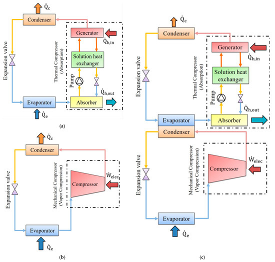
Figure 1.
General schematic of absorption–vapor compression combined cooling system: (a) Thermal compression (absorption) cooling system (ABC); (b) Mechanical compression cooling system (VCC); (c) ABC–VCC combined cooling system.
The classic mechanical vapor compression cooling cycle works by absorbing heat through the evaporator from the volume that is maintained at a low temperature, then releasing that heat through the condenser to the high-temperature media after adding electrical energy via the mechanical compressor. While the absorption cooling system’s working principle is similar to that of the traditional mechanical vapor compression cooling system, it uses an absorber to elevate the weak refrigerant through the pump then the heat is supplied to the generator rather than the mechanical compressor [19,48]. Different methods can be used to combine thermal and mechanical compression cycles. With this combination, we may divide the combined cooling cycle’s compression ratio between the two cycles under consideration. More performance and primary energy saving benefits can be seen as a result.
2.2. Different Cycle Configurations and Connections of ABC–VCC Combined Cooling System
The pressure difference between the two heat sources can be divided, with the mechanical compressor completing some of the pressure and the thermal compressor finishing the remainder, which is one of the key advantages of using thermal and mechanical compression in the combined cooling cycle. Numerous alternative refrigerants with little to no impact on the ozone layer and global warming have been developed for use in VCC applications in light of the environmental issues posed by conventional VCCs [16]. Besides this, absorption cooling technology provides an opportunity to utilize waste heat and renewable-based thermal energy. Integrating these two cooling systems results in less primary energy usage with higher efficiency as well as a zero or minimum environmental effect. However, the refrigerant selection used in VCC and the working pairs used in ABC are strong effects on the system operating parameters such as pressure levels, mass flow rates, cooling load, etc. Furthermore, the climate conditions; type, temperature and capacity of the thermal energy source; cooling or refrigeration load magnitude and temperature; sizes of the components; and economic parameters must be considered in the design of the combined system. Additionally, the combined VCC–ABC system needs to be designed to function harmoniously. Therefore, the design of a combined VCC–ABC system is challenging work. There is no universal system satisfying all requirements and overcoming all limitations depends on the application aim and the system. Therefore, scholars and designers have been conducting research for different cycle configurations and connections for the ABC–VCC combined system. This section reviews the current literature considering different cycle integrations and layouts of the ABC–VCC combined cooling systems. Overall and subsystem performance parameters based on energy and/or exergy analysis as well as economic evaluation and environmental impact are considered in the review work. Table 1 summarizes the ABC–VCC combined cooling system according to different configurations and illustrates the working fluids, operating conditions, and type of investigation for each study.

Table 1.
ABC–VCC combined cooling system according to different configurations and connections.
Cimsit et al. [49] have researched the thermodynamic analysis of absorption–vapor compression combined cooling cycles using different working pairs. In their study, the comparative thermodynamic analysis was made using LiBr- and - in the absorption chiller. On the contrary, three different working fluids were utilized in the vapor compression unit, namely R134a, R410A, and . The configuration of the combined system is such as in Figure 1c. This research focused on the performance indicators as well as the electric energy saving in ABC–VCC combined cooling system by utilizing different working fluids in both cooling units. The highest coefficient of performance was obtained by using LiBr- and in absorption and compression chillers, respectively, and reached up to 0.592. On the contrary, the lower coefficient of performance was obtained by using - and R410A in both absorption and compression units and reached up to 0.393. This study also revealed that using this combination compared with the traditional vapor compression cooling system alone can reduce the electric energy consumption by 48–51% under the same application conditions.
Han et al. [50] investigated a novel combined chiller consisting of absorption with a mechanical compressor powered by a mid-temperature from a waste heat source. The cooling subsystems share the same heat exchangers (evaporator and condenser). The absorption chiller integrated with the compressor uses ammonia–water as a working pair. The comparative analysis between the combined chiller and traditional absorption chiller revealed that the coefficient of performance reached 0.71 and 0.5, respectively, while the cooling capacities reached 157.8 kW and 107.6 kW, respectively. Thus, the proposed system can supply 46.7% more cooling power than the traditional absorption chiller using the same working pair. On the contrary, according to the results, the exergy efficiency values of combined and conventional absorption chillers were 24.6% and 16.7%, respectively.
Lijuan et al. [51] have numerically and experimentally investigated the absorption–vapor compression combined cooling system to provide a 3 kW as a cooling capacity. The absorption chiller uses LiB/ as a working pair, while the vapor compression chiller uses R22 as a refrigerant. The two chillers were connected by an evaporator sub-cooler and a heat exchanger between the compressor and condenser in VCC. The experimental results pointed out that the system can provide a cooling effect and COP about 2.56 and 1.9 times higher than the conventional absorption cooling system when the generating and evaporator temperatures are 80 °C and 10 °C, respectively.
Ustaoglu [52] has conducted a parametric study of working fluid selection and advanced exergy analysis for the absorption–compression combined cooling system. The two chillers share the same heat exchanger, an evaporator in the absorption unit and a condenser in the compression unit, as in Figure 1c. The investigations have been made on several types of refrigerants in the VCC, such as R717, R124a, R290, R152a, R507a, and R407c, whereas - was employed as a working pair in the ABC. In the advanced exergy analysis study, the author split the exergy destruction into avoidable–unavoidable and endogenous–exogenous parts to determine the interdependency of the system components and reveal each element’s enhancement potential. The research results showed that the most considerable exergy destruction occurred in the generator, evaporator, and absorbers reaching up to 53.8%, 9.67%, and 8.31%, respectively. Besides that, the highest and lowest exergy destruction occurred for R507a/- and R152a/-. The author also calculated the interactions among the system components by utilizing advanced exergy analysis. The results revealed that approximately 49.54% of the exergy destruction occurred in the interaction between the components and 50.46% was due to the components themselves. The findings also demonstrated that the highest overall coefficient of performance was 0.521 by employing R152 or R134a in the vapor compression chiller.
Wang et al. [53] have conducted a performance analysis of the absorption–vapor compression combined cooling system recovering condensation heat for a generation. The authors investigated the comparative performance between traditional absorption chiller and traditional absorption using two vapor compressors and a sub-cooler in the combined cooling system. The - working pair was used in the system studied. The purpose of using the recovering condensation heat for a generation (RCHG) in the combined chiller was to replace the part used for the input heat required. The research results stated that utilizing the RCHG with ABC can reduce the generation heat input by 70–80% compared with ABC without RCHG. Moreover, using this combination leads to minimizing the size of the condenser–sub-cooler of ABC. The calculative results indicated that using two-stage vapor compressors in the RCHG-ABC was suitable because it enabled the effective control of the discharge temperature leading to an increase of the primary energy efficiency (PEF) and the cooling capacity of the combined chiller by 2.2%.
Colorado et al. [54] have made a performance comparison between VCC and ABC–VCC combined cooling systems for single- and double-stage systems using two different refrigerants in VCC (R134a and ), whereas LiBr- was adopted as a working pair in the ABC system. The two chillers shared the same heat exchanger at the intermediate temperature level. The type of connection is as shown in Figure 1c, but the kind of each cooling cycle is different. The computed results indicated that electrical energy consumption is 45% lower if the (VCC–ABC) combined chiller is considered compared to a typical VCC under the same operating conditions and refrigerants. The COP of a dual-stage combined chiller is higher than that of the single-stage combined chiller, where the values increased up to 36.3% (0.58-0.91) for R134a and LiBr- compared to 45.2% (0.46–0.84) for and LiBr-.
Liu et al. [55] have studied two absorption–vapor compression combined cooling systems utilizing R1234yf/ionic liquid as a working pair in terms of a performance comparison. The difference between the two chiller types investigated was the vapor compressor position. The compressor position in the first type was between the evaporator and absorber, while it was between the condenser and generator in the second type. The investigations were made by employing three types of working pairs, which are R1234yf/[HMIM][TFO], R1234yf/[HMIM][], and R1234yf/[HMIM][. The results revealed that the COP of the combined chiller when putting the vapor compressor between the evaporator and the absorber was larger than that between the generator and condenser. Besides that, the R1234yf/[HMIM][TFO] working pair could provide better performance than the other working pairs considered.
Babaei et al. [56] have investigated the effect of using three nanoparticles (Fe, , and ) dissolved in aabsorption-recompression cooling cycle. A single-stage absorption unit is connected with a vapor compression unit, where the condenser of the vapor compression unit was linked with spiral coils from the generator. The vapor compressor was located between the condenser and generator to supply the required heat energy. The LiBr/ working pair was used in the absorption chiller, while was employed in the vapor compression unit. Different volume fractions (0–5 vol%) were considered in some sections of the introduced cycle. The computed results revealed that the heat transfer performance increased in the system’s components; thus, lower heating energy was required to accomplish the task in the generator, and a reduction of the power consumption was observed. The observed enhancements of the conductive and convective heat transfer of using (Fe, and , ) led to the improvement of the total heat transfer coefficient by 3.95%, 2.3%, and 7.4% for 5 vol%, respectively. The results indicated that using 5 vol% of Fe as nanoparticles led to improvements in plate heat exchanger efficiency, reduction of the compressor power consumption, and COP improvement of the proposed cycle, reaching up to 7.6%, 11.8%, and 14.6%, respectively.
Dixit et al. [57] have analyzed thermodynamically and thermo-economically the cooling system consisting of a combined two-stage absorption system with a compressor that split between them and compared the results with the traditional two-stage absorption cooling system. The LiBr/ was chosen as a working pair in the system. The proposed systems required 7–10 °C lower generating temperature than the traditional one. Besides that, there was a specific value of the generating temperature at which the COP and exergetic efficiency provide maximum values. Additionally, the increase of compressor pressure led to a rise in both COP and yearly cost; however, it reduced the system’s size and exergetic efficiency. The optimization results reduce the annual system’s cost by 5.2%.
Jain et al. [58] have thermo-economically and environmentally analyzed the absorption–vapor compression combined cooling system using a non-dominated sort genetic algorithm (NSGA) technique. The objective functions were the total product cost and the overall irreversibility rate. The LiBr- working pair and R410A refrigerant were used in the absorption and compression chillers. The two chillers share the same heat exchanger (an evaporator in the ABC and a condenser in VCC), as shown in Figure 1c; 0% and 7.5% are the percentage deviation results from the thermodynamic and total product cost, respectively. The results illustrated that multi-objective design values for the hybrid thermodynamic and total product cost were the best among overall product cost and single-objective optimized designs.
Cimsit et al. 59 have investigated the vapor compression–absorption combined cooling cycle in terms of its thermo-economic optimization. The two chillers consisted of the essential components and shared the same heat exchanger, which is an evaporator in the absorption unit and a condenser in the vapor compression unit, as in Figure 1c. The LiBr-H2O working pair and R410A refrigerant were used in the absorption and compression chillers. Optimization has been performed in this research by employing a non-linear simplex direct search method. The results illustrated that the maximum exergy loss and exergy destruction happen in the evaporator. The maximum and minimum exergy efficiencies occurred in the generator and evaporator by 74.4% and 11.89%, respectively. The exergy efficiency and minimum objective function reached 7.3% and 4.05%, respectively. However, by applying the thermodynamic optimization, the minimum objective function decreased by 3.3%, and the exergetic efficiency and the coefficient of performance enhanced by 3.1% and 7%, respectively.
Garimella et al. [60] have developed a thermodynamic model to investigate the performance of the absorption–vapor compression combined cooling system for naval ship applications. The two chillers consisted of the essential components and shared the same heat exchanger: an evaporator in the absorption unit and a condenser in the vapor compression unit. The LiBr- working pair and CO2 refrigerant were employed in the absorption and compression chillers. The results showed that the individual coefficient of performance for vapor compression and absorption cycles were 2.173 and 0.7803, respectively, for a 51 MW cooling capacity at −40 °C evaporator temperature. The results revealed that performing this cycle reduced electric consumption, reaching up to 31%. Thus, minimizing the fuel requirements and ship weight and increasing the cruising range.
Jain et al. [61] have analyzed the performance of the absorption–vapor compression combined cooling system with an undersized condenser and evaporator. The two chillers share the same heat exchanger, an evaporator in ABC and a condenser in VCC, as in Figure 1c. The LiBr/ working pair and R22 refrigerant were used in the absorption and compression chillers. The results indicated a reduction of power consumption in the vapor compressor reaching up to 67%. However, this reduction decreased when the evaporator and condenser were foul by 9.22%. The total coefficient of performance was also reduced when both components were foul by 4.7%. Additionally, the overall system efficiency was reduced when both parts were dirty by 10.5%.
Jain et al. [62] have presented a parametric study and thermodynamic modeling of the absorption–vapor compression combined cooling system to optimize the condensing temperature by utilizing the modified Gouy-Stodola equation. The two chillers share the same heat exchanger, an evaporator in ABC and a condenser in VCC, as in Figure 1c. The / working pair and R744 refrigerant were used in the absorption and compression chiller. The computed results stated that the optimum condensing temperature was −13 °C for a 175 kW cooling capacity. Besides that, the proposed system can reduce the PEC (primary energy consumption) by 60.6%, and the electrical COP value was better by 153.6% compared with a two-stage vapor compression cooling system.
Jain et al. [63] have investigated the absorption–vapor compression combined cooling system in terms of a thermo-economic analysis utilizing a non-linear programming mathematical model. The two chillers share the same heat exchanger, an evaporator in ABC and a condenser in VCC, as in Figure 1c. The LiBr- working pair and R410A refrigerant were used in the absorption and compression chiller. The primary purpose of this investigation was to reduce the total yearly cost of the system, which consisted of the capital costs and exergy input costs. During the analysis, the authors found that higher generator and evaporator temperatures are not necessary to obtain optimum results. However, they declared that the lower condensing temperature could enhance the overall system performance regarding exergy and energy analysis. Yet, it is not economical due to the system size and cost. The thermo-economic optimization results revealed that the total annual cost of the proposed system was reduced by 11.9%, with a 22.4% decrease of investment cost.
Jain et al. [64] have compared the traditional vapor compression chiller performance with three absorption–vapor compression cooling combined systems (parallel, series, and integrated series-parallel) in terms of an exergy, economic, energy, and environmental analysis as well as optimization. The LiBr- working pair and R410A refrigerant were employed in the absorption and compression chiller. In the series form, the two chillers share the same heat exchanger, an evaporator in ABC, and a condenser in VCC, as illustrated in Figure 1c. In a parallel layout, the input chilled fluid to the VCC’s evaporator was linked to the outlet cooling fluid from ABC’s evaporator. The integrated series-parallel design combined the first and second configurations in one system. The results indicated that the power consumption in the compressor of series, parallel, and integrated arrangments decreased by 76.6%, 50%, and 88.3%, respectively. Yet, by implementing the optimization tool, the reduction reached 78.1%, 60%, and 89.5%, respectively. Furthermore, the irreversible losses were 44.60 kW, 32.89 kW, and 38.55 kW compared with 33.28 kW for the VCC. The capital cost reached up to 3.6, 3.1, and 4.4 times more than VCC. The payback period for the three forms reached up to 8.8, 11.7, and 9.3 years, respectively, whereas if the optimization tool has applied, the payback reached up to 7.4, 10.4, and 8.7, respectively. Moreover, the CO2 emissions in the three arrangements above were 76.6%, 50%, and 88.3% less than those for VCC. Finally, the yearly operation costs for the three forms were 20.9%, 13.8, and 24.7% lower than that in VCC; however, if the system optimization was applied, the operation cost reduction reached up to 8.5%, 8.1, and 4.7%, respectively.
Jain et al. [65] have analyzed the thermodynamic performance of the absorption–vapor compression combined cooling system. The two chillers shared the same heat exchanger, an evaporator in ABC and a condenser in VCC, as in Figure 1c. The LiBr/ working pair, R22 as a primary refrigerant, and (R410A, R407C, and R134A) alternative refrigerants were used in the absorption and compression chillers. The results showed the coefficient of performance of VCC in the combined system was improved by 155%, and the electric power consumption decreased by 61%. The results also stated that all the alternative refrigerants could be used as a potential alternative for R22. Besides that, the irreversibility rate of the system was also investigated. It was found that decreasing one unit of the irreversibility rate in the condenser led to a 3.8 times bigger decrease in the total irreversibility of the proposed system. In contrast, a unit decreasing the irreversibility rate in the evaporator led to it decreasing by 3.4 times in the total irreversibility of the same system.
Sachdeva et al. [66] have investigated the absorption–vapor compression combined cooling system in terms of an energy analysis. The two chillers in the proposed system shared the same heat exchanger: an evaporator in ABC and a condenser in VCC, as in Figure 1c. The - working pair and R407C as a refrigerant were employed in the absorption and compression chillers. The research results revealed that the performance of the vapor compression chiller in the proposed system was enhanced by 146%, and the electrical consumption decreased by 64%. Besides that, the requisite heat for the proposed system increased with the increasing of the cooling power, and the efficient usage of the heat reached up to 83.3 kW.
Jain et al. [67] have analyzed the absorption–vapor compression combined cooling system in terms of the exergy approach utilizing the modified Gouy-Stodola equation. The two chillers in the proposed system shared the same heat exchanger: an evaporator in ABC and a condenser in VCC, as in Figure 1c. The LiBr- working pair and R22 refrigerant were used in the absorption and compression chillers. The results indicated that using higher evaporator and generator temperatures enhanced the overall system performance, yet higher absorber and condenser temperatures decreased the system performance. The coefficient of the structural bond value was also analyzed; the results demonstrated that this value for the evaporator, cascade condenser, generator, condenser, and absorber are 66.67, 11.75, 0.82, 11.22, and 1.30, respectively. The previous values clarified that the evaporator in the proposed system was more sensitive than others in temperature changes. Additionally, power consumption decreased by 66.42% compared to the traditional compression cooling system.
Jain et al. [68] have investigated the vapor compression two-stage absorption-integrated cooling system with VCC in terms of an advanced exergy analysis and comparative study. The ABC and VCC share the same heat exchanger, an evaporator in the absorption chiller and a condenser in the vapor compression chiller, the type of connection is as illustrated in Figure 1c with a two-stage absorption system separated by a vapor compressor. The proposed system operated between four pressure levels, where an intermediate vapor compressor separated the two absorption stages in the absorption section. The LiBr- working pair and R717 refrigerant were used in the absorption and compression chillers. The results illustrated that the optimum generator temperatures in the low-pressure and high-pressure generators were 50.2 °C and 58.4 °C, respectively, compared with 85.5 °C in the normal absorption–compression combined system. However, the electrical power consumption for the proposed system increased by 21.4% compared with the ABC–VCC cooling system, yet it was 63% lower than that in the VCC alone. The electric COP of the proposed system (two-stage absorption) and ABC–VCC (one-stage absorption) cooling system were higher by 228.3% and 170.4%, respectively, compared with VCC alone. Besides that, the total irreversibility rate of the proposed system was 31.1% higher than that in the ABC–VCC cooling system and 34% lower than the VCC alone.
Kim et al. [69] conducted an experimental study on the absorption–vapor compression combined system for heat pump applications. Different mixtures of -O as a working pair were investigated to optimize the operating characteristics of the proposed system. The experimental results revealed that when the concentration is weak (0.421), the proposed system provided 10 kW as heating power and 90 °C as hot water by utilizing 50 °C as a heat source.
Wang et al. [70] have compared the performance of the double-effect absorption cooling cycle and absorption–vapor compression combined cooling cycle. -O working pair was employed in both systems. The results demonstrated that the primary energy efficiency of the combined cycle could reach up to 29% higher than the double-absorption-effect system, and it could reduce the generation heat by 23.3–69.5% compared with the dual-effect absorption cycle. Furthermore, utilizing the combined cooling cycle could reduce the generation temperature from 99 °C to 35 °C and the evaporator temperature from −2 °C to 26 °C compared with a double-effect absorption cycle.
Xu et al. [71] have comparatively studied the energy performance of two types of absorption–compression refrigeration systems. Low-grade temperatures drive the two different systems. The two chillers were linked with the cascade system, where the vapor compression chiller is in the bottom and the absorption system is at the top of the combined system. However, the first type of connection is by linking the ABC evaporator with the VCC condenser (EC). The second type connected the ABC evaporator with a sub-cooler (ES). Their investigation was focused on three energy performance indicators, namely heat transformation ratio, global COP, and COP of the subsystem. The researchers used - as a working pair in the absorption system and R22 refrigerant was adopted in the subsystem. The results revealed that the EC configuration gave a higher value of the COP subsystem than the EC one. The EC system also provided a higher COP subsystem than the ES in a constant cooling capacity. The authors recommended using the ES system when the cost of a low-grade temperature is high, as this system has a larger heat-transforming ratio than the EC system. The results also indicated that the EC system could save more energy when using low-evaporator and high-generation temperatures. In contrast, the ES system is better when using a high-evaporating and low-generation temperature according to the value of global COP.
JV and Dario [72] presented a parametric analysis of the cascade system using NH3-LiNO3, NH3-NaSCN and NH3-H2O in the absorption cycle and R134a in the compression cycle. The temperature ranges of the analyzed heat sources and condensation points in the compression cycle were 355–380 K and 281–291 K, respectively. Additionally, the influence of each economizer on the coefficient of performance was numerically calculated. As a consequence, the absorption cycle used NH3-NaSCN solution, while the compression cycle used R134a, both of which produced promising numerical results with the highest COPs. In comparison with a conventional vapor compression refrigeration system, a cascade system combining NH3-NaSCN and R134a as working fluids can reduce the amount of work required by the compressor by approximately 50%. The economizer that greatly improves the compression–absorption cascade system’s coefficient of performance for all working fluids under examination is the solution heat exchanger. The second economizer that improves the performance of the entire system is the refrigerant heat exchanger.
2.3. ABC–VCC with Different Heat Source Systems
Utilizing various thermal heat sources that may arrive from different sources is one of the key advantages of using a thermal compressor in the cooling cycle [73]. This section comprehensively reviews varying heat source systems that can be integrated with the ABC–VCC combined cooling system. Table 2 summarizes the ABC–VCC combined cooling system according to the different heat source systems and illustrates the working fluids, operating conditions, key findings, and types of investigations for each study.
Table 2.
ABC–VCC combined cooling system according to heat source systems.
Mousavi et al. [74] and Chen et al. [75] have studied the absorption–compression cooling system regarding exergy, exergoenvironmental, and exergoeconomica assessments for low-temperature applications. The proposed combined cooling system in their research consisted of three subsystems: (1) A ranking cycle to generate the required electrical power for the compressor and pumps, the working fluid used in this subsystem was a mixture of –; (2) An absorption cooling cycle (ABC) in a high-temperature level, where the working fluid was also a mixture of –; and (3) a vapor compression cooling cycle (VCC) in a low-temperature level, where the refrigerant used in this subsystem was . In their research, the combined cooling system studied was able to produce 60.65 kW as a cooling power with 0.268 as the overall coefficient of performance, and the total heat input was 226.56 kW. Besides that, the overall exergy efficiency was also computed to be 69%. However, the lowest exergy efficiency among the heat exchangers in the proposed combined cooling system is related to ABC, which was 65%. However, the highest exergy efficiency among the combined system components was 99.38%. They also clarified that the values of the apparatus exergy cost and the environmental impacts could be minimized by reducing the minimum temperature and increasing the input pressure.
Seyfouri et al. [76] have made a thermodynamic analysis of different absorption–compression cooling configurations driven by microturbines to supply cooling effects at low temperatures. The four system configurations used in this investigation are summarized as the following: Configuration A consists of the absorption unit that operates at a high-temperature level. In contrast, the vapor compression unit works at a low-temperature level. These two cooling units were connected by a heat exchanger that worked as an evaporator in the absorption section and a condenser in the compression system. A micro gas turbine simultaneously supplied both units the needed electricity and heat. Configuration B consisted of the same components of the previous configuration; however, the two cooling units were linked together using a sub-cool after the condenser of the VCC. Thus, the cooling effect of the absorption unit was used in the sub-cooler. Therefore, a small amount of heating was required to operate the absorption chiller. Configuration C comprised a two-stage compression cooling unit using an intercooler between the two compressors. Thus, less input work of compression was needed. The cooling capacity in the absorption unit was utilized in the intercooler. The heating demand in this arrangement was also low. Configuration D consisted of a two-stage compression chiller with an intercooler between the two compressors and a sub-cooler after the condenser of the VCC. In this arrangement, the ABC’s cooling effects were sequentially employed in the intercooler and sub-cooler. The energy utilized factor, which is defined as the cooling power produced to the system’s input, was compared between these arrangments. Their results revealed that the energy utilization factor for configurations A, B, C, and D are 73.8%, 19.6%, 99.6%, and 133%, respectively.
Seara et al. [77] have thermodynamically investigated the absorption–vapor compression combined cooling system. The configuration of the system studied comprised a single-stage vapor compression chiller at a low temperature and a single-stage absorption chiller at a high temperature. The two systems shared the same heat exchanger, evaporator in the absorption chiller, and condenser in the vapor compression chiller, as in Figure 1c. The refrigerants considered in the bottom cycle were and , while the working pair issued in the upper cycle was. A cogeneration system was powering the combined cooling system that consisted of a gas engine. Their study revealed that the intermediate temperature (condensation temperature in VCC) in the combined system was an essential parameter that had different effects on the coefficient of performance in the combined chiller studied, which was related to the evaporation temperature of ABC. The researchers also investigated the power requirement of the combined system proposed and the power supplied by the gas engine system. They declared that the vital energy required to provide the heat needed for the combined cooling system is higher than the eclectic required for the refrigeration system. The investigation’s results demonstrated that the global primary energy ratio () of the combined system reached up to 0.057 and 0.059 for and , respectively. While the overall coefficient of performance of the combined system reached 0.253 and 0.254 for and , respectively.
Agarwal et al. [78] have investigated the absorption–vapor compression combined cooling system in terms of an energy and exergy analysis. The proposed integrated cooling system consisted of a triple-effect absorption chiller at a high-temperature level connected with a vapor compression chiller at a low-temperature level. The working fluids used in the cooling system were LiBr/ and R1234yf for absorption- and vapor compression chillers, respectively. The exhaust of the gas turbine was driving the absorption section in this configuration; thus, lower electrical consumption was used in the combined cycle. The two chillers in the studied arrangement shared the same heat exchanger, an evaporator on the absorption side and a condenser in the vapor compression, as shown in Figure 1c in terms of connection. The use of the system was to provide cooling effects at low temperatures for ice making, frozen food, and chemical reactions by using waste heat from gas turbines. The investigation revealed that electrical consumption was reduced by 45.84% compared to the conventional chiller. Additionally, the performance of VCC has increased by 85.26%. In terms of its exergetic efficiency, the improvements reach up to 85.28%, with a lessening in total exergy destruction reach up to 70.8%. The performance and exergy investigations have also been performed and evaluated at different operating conditions, such as at a high-pressure generator temperature, absorber temperature, and evaporator temperature.
Jianbo et al. [79] have experimented and tested the absorption–vapor compression combined cooling system to provide a 3 kW cooling effect for automobiles. The integrated cooling system studied used the vehicle’s exhaust gas heat to power the devices in the combined system. The working pairs employed in the tested system were R124/dimethylacetamide (DMAC) and R124 for the absorption and vapor compression chillers, respectively. The rig tested was driven by hot air that simulated the exhaust gas from the vehicle’s engine. The researchers have investigated the cooling capacity of two system configurations where the results reach up to 2.4 kW and 2.95 kW for an absorption cooling sub-cycle and combined cooling cycle, respectively. The researchers also indicated that the system performance of the absorption cooling sub-cycle was affected by the ambient air, heat air, and cooler water temperatures.
Marimon et al. [80] have published a study on energy and economic investigations of trigeneration arrangements for supermarkets in Spain. The proposed system was introduced to provide refrigeration, heating, and electricity demands in the studied place. The trigeneration system consisted of an ammonia/water absorption cooling unit, a cogeneration engine, and a vapor compression system. The purpose of this system was to provide the cooling capacity needed in a supermarket. The research results revealed that the investment payback would be approximately 6.4 years, according to the Spanish conditions. Besides that, the emissions of the trigeneration system will be around 22.7 tons .
Razmi et al. [81] have investigated a cogeneration system consisting of four units to supply several types of energy (heating, cooling, and power) with low environmental effects and high efficiency. The four designs were the following: (1) compressed air energy storage (CAES) that used air as a working fluid; (2) the organic Rankine cycle (ORC) that employed R407C as a working fluid; (3) the absorption cooling cycle (ABC) that selected LiBr/ as a working pair; and (4) the vapor compression cooling cycle that utilized water as a working fluid. The investigation of this system was executed in terms of energy and exergy analyses. The calculated results indicated that the electrical power and the cooling capacity during the peak period that can be simultaneously generated were 2280 kW and 416.7 kW, respectively. Besides that, the results indicated that the exergy efficiency of the components reached 49.17% in the cogeneration system. The coefficient of performance for the absorption–vapor compression cooling system reached 3.78.
Patel et al. [82] have investigated the absorption–vapor compression combined cooling system integrated with the organic Rankine cycle in terms of its thermo-economic optimization. The proposed system consisted of VCC that selected R410A as a refrigerant and ABC used LiBr/ as a working pair. Both chillers shared the same heat exchanger (an evaporator in the ABC and a condenser in the VCC). The type of ABC–VCC connection was as depicted in Figure 1c. Besides that, the two chillers were linked with an organic Rankine cycle to provide the heat and electric energies needed. The results showed that the energy efficiencies for cooling and heating modes were 22.3% and 79%, respectively. The computed coefficient of performances for VCC, ABC, and combined chiller were 4.41, 0.75, and 0.54, respectively. The results also clarified that the optimized operating values of evaporator temperature and desorber were −15 °C and 84.9 °C, respectively. Besides that, using these optimized values reduced the payback period from 5.26 to 4.5 years.
He et al. [83] have evaluated the absorption–vapor compression combined cooling system in terms of its performance and energy consumption. The proposed chiller consisted of three VCC, ABC, and solar systems to drive the absorption unit. The working pair used in the ABC was LiBr/, whereas an R134a refrigerant was employed in the VCC. The two systems shared the same heat exchanger (an evaporator in the ABC and a condenser in the VCC). The research’s results revealed that the performance of the proposed system was increased by 133.33%, while the power consumption was decreased by 20.8% compared to the compression chiller. Moreover, a better economic performance was also reported by using the proposed system. Besides that, the results revealed that optimum evaporating and generating temperatures provide maximum performance and minimum energy consumption for the suggested system.
Song et al. [84] have thermodynamically investigated the performance and energy consumption of solar absorption–dual-compression combined refrigeration cycles (SADCCRCs) for the application of temperature and humidity independent controls. The proposed system used LiBr/ as a working pair in the absorption chiller, whereas R134a was selected for the compression chiller. The proposed system worked in three modes depending on the solar intensity (high (I), medium (II), and low (III)). The proposed system was evaluated thermodynamically in terms of its generating, evaporating, and ambient temperatures and the results were compared with the solar absorption–compression combined refrigeration cycles (SACCRC). The results revealed that there were optimum evaporating and generating temperatures to achieve the lowest energy power consumption depending on the operating mode (I, II, and III). The study also presented the best economic performance in terms of the solar collector areas when comparing the SACCRC and the conventional solar single absorption refrigeration cycle (SSARC). The highest reduction of the solar collector reached up to 55.79% at 450 w/ of the low solar intensity. The results also show that the reduction of the power consumption reached 61.47% when comparing the proposed system with the solar absorption–compression combined cooling system.
Su et al. [85] have thermodynamically investigated the absorption–vapor compression cooling system integrated with liquid desiccant dehumidification. This system provided the diluted liquid desiccant solution by recovering the condensation heat from the absorption system’s condenser. The compressor considered in this cycle was utilized for modifying the generating pressure and condensation temperature. The solution selected for air dehumidification was LiCl-water, whereas LiBr/ was used as a working pair in the absorption–compression cycle. The results indicated that the proposed system’s primary energy efficiency (PEF) was 34.97% higher than the conventional absorption–air conditioning system under the same working conditions. Besides that, the proposed system could also adjust the generating and evaporating temperature from 100 °C to 60 °C and from 6 °C to 18 °C, respectively.
Patel et al. [86] have thermo-economically analyzed the novel absorption–vapor compression combined cooling cycle integrated with the organic Rankine cycle. The two chillers shared the same heat exchanger: an evaporator in the ABC and a condenser in the VCC. The organic Rankine cycle provided the requisite heat to the ABC and electrical power to the VCC. The LiBr/ working pair and R410A refrigerant were used in the absorption and compression chiller. The thermo-economical analysis for the proposed cycle reveals that the payback period for the system is about 6.2 years.
Kairouani et al. [87] have investigated the energy-saving and cooling performance of an absorption–vapor compressor cooling system integrated by geothermal energy. The two chillers shared the same heat exchanger: an evaporator in the ABC and a condenser in the VCC. The –O working pair was used in the absorption chiller, while three different refrigerants (R717, R22, and R134a) were employed in the compression chiller. The proposed system could enhance the coefficient of the performance by 37–54% compared with the traditional cycle. Moreover, the cooling capacity reached 464 kW and 415 kW if the VCC operates with R717 and R134 or R22, respectively.
Sun [88] has experimentally investigated the integration between the gas engine-absorption–vapor compression combined cooling system. The gas engine provided the heat energy to operate the absorption chiller, supplying the power to operate the vapor compression chiller. The two chillers shared the same heat exchanger: an evaporator in ABC and a condenser in VCC. The LiBr/ working pair and R22 refrigerant were used in the absorption and compression chillers. The experimental results stated that the cooling capacity reached 596.2 kW at 1800 rpm as a gas engine speed. The author observed that the cooling capacity decreased while the energy utilization ratio increased, reducing the gas engine’s speed. Besides that, the primary energy ratio of the tested system reached 1.84.
Mohammadi et al. [89] have compared the absorption–vapor compression combined cooling system utilizing four different strategies in terms of its energy and exergy. The LiBr/ working pair and R22 refrigerant were used in the absorption and compression chiller. The system was powered by a micro gas turbine that provided heat energy to the absorption chiller and electric energy for the compression chiller and other facilities. The four different configurations used in (41) were explained as the following: (A) the two cooling units were cooled by air: (B) the absorption unit was cooled by air, while the vapor compression unit was cooled by water; (C) the absorption unit was cooled by water while the vapor compression unit was cooled by air; and (D) both chillers were cooled by water pumped through parallel tube line. The results stated that energy usage efficiency was boosted by up to 50% compared to a conventional chiller. However, water consumption in the proposed system was increased by up to 35% compared to the traditional system. Configuration D had the highest water consumption and second lowest efficiency among the others considered. However, the results revealed that configuration B was the best among the others considered, especially in dry places.
Boyaghchi et al. [90] have investigated the absorption–dual-evaporator vapor compression combined cooling system in terms of its exergoeconomics and optimization. The two chillers shared the same heat exchanger: an evaporator in the ABC and a condenser in the VCC. The LiBr/ working pair and R1234yf, R134A, R1234ze, R22, and R407C refrigerants were employed in the absorption and compression chillers. The solar plate collector was used to provide the heat energy to the absorption chiller that used /Cuo nanofluid as a heat transfer medium. The optimization was performed using the Genetic algorithm-II method with three objective functions: total cost rate, exergy, and thermal coefficient of performances. The results showed that the R134A refrigerant had the highest daily exergy and energy coefficient of performance, reaching 0.5815% and 9.34%, respectively. On the contrary, the R1234ze refrigerant had the best total product cost rate in terms of its exergoeconomics, reaching up to USD7016 annually. Morover, the optimization results pointed out that R134A provided an improvement in the daily exergy and energy coefficient, reaching up to 2% and 2.4%, respectively, with 680 as a minimum solar collector area. On the contrary, by utilizing R1234ze, the reduction of the total cost rate reached up to 2.4% with 702.01 and 0.041 as the maximum solar collector area and nanoparticles, respectively.
Jeong et al. [91] have investigated the static characteristics in addition to the efficient control of the absorption–vapor compression combined cooling system. The two chillers were connected by the chilled fluid that flows to the evaporator of the ABC to cool down and then flows through the evaporator of the VCC. The proposed system was driven by a gas engine that was providing the necessary heat energy to the ABC and the power to the VCC. The LiBr/ working pair and NH3 refrigerant were used in the absorption and compression chillers. The investigation was carried out using two control methods; the first involved changing the input gas flow and sub-heat flow rates, while the other involved changing the input gas flow and hot fluid flow rates. The results revealed that the second method was more efficient. The results also illustrated that the coefficient of the performance reached up to 1.87, yet at half-load operation the performance raised by 14% due to it manipulating the hot fluid flow and input gas flow rates.
Wang et al. [92] have investigated the performance of the absorption–vapor compression combined cooling system utilizing the solar system to provide the necessary heat energy. The LiBr- working pair and R134A refrigerant were used in the absorption and compression chillers. The coefficient of performance for the proposed system reached up to 6.1 by using 700 W/ as solar intensity. Additionally, the power consumption of the proposed system was reduced by 50% compared to the traditional VCC. The results also pointed out that the proposed system’s performance boosted as the sunlight intensity increased.
Chen et al. [93] have investigated the performance of an absorption–vapor compression combined system integrated with another single absorption cooling system utilizing flue gas as a heat source. The proposed system shared the evaporator, condenser, absorber, and other secondary components. The flue gas flowed into the higher pressure reboiler (single absorption sub-cycle) and then into the low-pressure reboiler (absorption–compression sub-cycle). O as a working pair was employed in the proposed system. The results revealed that the cooling effect of the suggested system increased by 28.21% compared with the traditional system. Additionally, the exergy efficiency reached 25.94%. The results also clarified that when the heat temperature was 114 °C at a high-pressure reboiler, the cooling power per mass of flue gas reached 59.33 kJ/kg.
Xu et al. [94] have evaluated and optimized the hybrid system consisting of an absorption–sub-cooled vapor compression chiller using the solar system as a heat source. The link between the two systems occurs in the sub-cooler of the VCC (bottom chiller) and the ABC (upper chiller) evaporator. The heat source provided by the solar system was utilized to heat the generator in the absorption chiller. In contrast, the cold storage system was linked to the VCC evaporator of the hybrid cooling system. LiBr- was used as a working pair in the absorption system, while Ammonia was the refrigerant adopted in the VCC system. The optimization investigations using the genetic algorithm reveal that the proposed system size of 0.04–0.06 kW/ and the volume of the cold storage tank of 40–60 L/ when the area of the solar collectors is 2000 . The results also pointed out that the yearly energy savings of electricity and payback period were 68.8 kWh/ and 4.96 years, respectively.
Chen et al. [95] reported a theoretical and experimental work dealing with a solar-assisted hybrid air-cooled adiabatic absorption and vapor compression air conditioning system that consisted of two coupled modes: the sub-cooling mode and the cascade mode. The experimental results of the cascade mode show that the COP of the VCC significantly increases with the growth of the hot water temperature, with a maximum increment of 162.0% when the hot water inlet temperature is 90 °C. The simulation results show an increment of 63.9–166.7% in the electric COP of the system in the cascade mode, which is similar to the experimental findings. It is concluded that the sub-cooling mode driven by the compound parabolic collector is applicable to residential buildings due to its distinct advantages, namely its lower levelized cost of cooling at 0.06 USD/kWh, shorter payback time of 8.54 years, and smaller collector area of 11.41 m2, in comparison with other configurations.
3. Adsorption (Thermal Compression)–Mechanical Vapor Compression Combined Cooling Cycles
3.1. Operating Principle
As described in Section 2, the mechanical compressor, expansion valve, condenser, and evaporator are the four main components of the classic mechanical vapor compression (mechanical compression) cooling cycle. While the basic adsorption (thermal compression) cooling cycle consists of the following main components: the evaporator, the two solid sorption beds, the condenser, and the expansion valve [63]. Figure 2 illustrates the general schematic of mechanical and thermal (adsorption) compression chillers separately and combined.
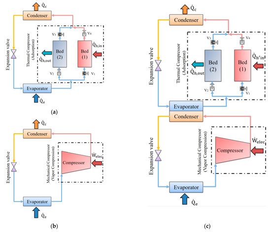
Figure 2.
General schematic of adsorption-vapor compression combined cooling system: (a) Thermal compression (adsorption) cooling system (ADC); (b) Mechanical compression cooling system (VCC); (c) ADC–VCC combined cooling system.
The vapor mechanical cooling cycle works by absorbing heat from the area that has to be cooled or heated through the evaporator and releasing it through the condenser after adding electrical energy via the mechanical compressor. The adsorption cooling system operates on a similar concept as the traditional vapor cooling system. However, the adsorption system uses the thermal compressor, which is represented by two solid sorption beds, rather than the mechanical compressor. Adsorbent and adsorbate are the working pair in the solid sorption bed. The adsorption phenomenon illustrates that the adsorbate particles settle down at the surface and inside the pores of the adsorbent due to the strong, attractive forces between the particles. Additionally, the adsorbent desorbs the refrigerant when it is heated up by an outside source and adsorbs the refrigerant when an outside cooling source cools it down. Thus, the adsorption cooling system requires two external sources; one might come from a waste heat source with a relatively high temperature, and the other might come from a low-temperature source such as the ambient temperature. The evaporator of the adsorption cooling system absorbs heat from the place to be refrigerated or conditioned. The thermal compressor conveys this heat to be released through the system’s condenser after accomplishing the required pressures in the thermal compressor [96]. The combination of thermal compression and mechanical compression cycles can be executed in different ways. This combination divides the compression ratio of the combined cycle between the two cycles considered. Thus, more performance and energy advantages can be observed.
3.2. Different Configurations and Connections ADC–VCC System
The pressure ratio between the two heat sinks is fragmented when the thermal and mechanical compressors are used in the combined cooling cycle, with the mechanical compressor handling some of the pressure and the thermal compressor handling the remainder. In the design stage, most of the parameters summarized in Section 2.2 are valid for the adsorption cooling cycle. Both adsorption and absorption processes are part of the sorption phenomena, yet they are quite different from each other. Absorption is the particle disintegration of one substance into another to create a solution. On the other hand, adsorption refers to the physical attraction between a vapor and a solid surface. Adsorption and absorption, the two ideas employed in refrigeration systems, differ greatly in terms of the heat source, operational factors, maintenance requirements, and longevity. A successful adsorption process is achieved by using a suitable adsorbent in terms of adsorption kinetics and adsorptive capacity. Understanding the adsorption properties of the used adsorbent–adsorbate pair under varied temperatures and pressure is necessary for the design of an adsorption refrigeration system. An adsorbent–adsorbate combination’s unique combined feature is termed the isosteric heat of adsorption. Each adsorbent–adsorbate pair often has completely unique adsorption properties. To build the adsorption-based cooling cycle system, precise information regarding the adsorption isotherms of the various adsorbent–adsorbate pairs as well as the isosteric heat of adsorption must be understood. The suitable adsorbate must be chosen based on a number of factors including: thermal stability, flammability, toxicity and explosion, latent vaporization heat, compatibility, ODP, and GWP. Various types of refrigerants can be utilized in adsorption cooling systems. In the market, we can find suitable refrigerants including water, ethanol, methanol, and ammonia that can be used in the adsorption system. Furthermore, a variety of refrigerants, including hydrogen, methyl alcohol, R22, R732, oxygen, R134A, etc., are being studied for use in adsorption applications. The ideal functioning pair is one that is in agreement with the fundamental specifications, which change based on the application [43,97]. It is regrettable that adsorption statistics are not accessible from adsorbent producers [30]. When compared to known ones, the features of a new adsorbent, such as a silica gel or activated alumina, may differ. Adsorption isotherms of various adsorbent/adsorbate pairs and the isosteric heat of adsorption must be evaluated in order to construct an adsorption-based cooling cycle [20]. Working temperatures, number of beds, cycle time and operating procedures, internal heat recovery, etc., all also have a strong effect on the ADC performance. In addition, the combined VCC–ADC system must be designed to work in harmony. Therefore, the design of a combined VCC–ADC system is challenging. There is no universal system satisfying all requirements and to overcome all limitations depends on the application of the aim and the system. Therefore, scholars and designers have been conducting research for different cycle configurations and connections for the ADC–VCC combined system. This section reviews different connections and layouts of the ADC–VCC combined cooling system. Table 3 summarizes the ADC–VCC combined cooling system according to different configurations and illustrates each study’s working fluids, operating conditions, and type of investigations.
Table 3.
ADC–VCC combined cooling system according to different configurations and connections.
Kiliç and Anjrini [96] have comparatively evaluated the performance of the mechanical- and adsorption-integrated cooling system for two different configurations. The first layout was the cascaded connection system using the intermediate heat exchanger (VCC condenser and ADC evaporator), whereas the serial connected (VCC–ADC) evaporator was the second layout. Three types of adsorbents with water were used as a working pair in the combined system’s adsorption chiller, namely RD silica gel, RD silica gel 2060, and silica gel-LiCl, while R152A working fluid was adopted in the mechanical compression chiller. The purpose of the study is to appraise the performance and electrical energy saving ratio of the proposed combined system that produces a total cooling capacity of 10 kW using the two configurations and the three different adsorbents. The results demonstrated that the highest overall system performance was achieved by employing a silica gel-LiCl–water working pair in the adsorption chiller, reaching up to 0.35. The increasing ratio values of the overall system performance using the cascaded connection are higher than those of the parallel connection. The authors also reveal that increasing the adsorption cycle time will improve the overall system performance, reaching up to 16% within the operating conditions studied. The results also indicated that the electrical energy saving ratio when using the cascaded and serial evaporator connections reached 65% and 59%, respectively, within the operating conditions considered. The study also investigated the performance of the two chillers separately and combined with the two layouts. The increase of the VCC and ADC chillers reached 2.86 and 1.046 using the cascading type, respectively.
The effectiveness of the combined adsorption–vapor compression cooling system has been examined by Banker et al. [98]. In the adsorption cycle and the vapor compressor, respectively, HFC 134A refrigerant and activated carbon were used. Two configurations were used to carry out the investigation: After the evaporator, where the refrigerant enters the vapor compressor following desorption, the thermal compressor supplied low-grade compression. On the other hand, in the second arrangement, the vapor compressor offers low-grade compression where the vapors enter the thermal compressor to finish the cycle following the mechanical compressor. The findings showed that when the thermal compressor functioned in low-pressure stages, there was little impact from switching between the thermal and mechanical compression systems.
Two distinct adsorption–vapor compression combined cooling cycle architectures have been analytically examined by Uddin et al. [99]. According to Figure 2c, the initial arrangement had the two systems using the same heat exchanger (a condenser in the vapor compression chiller and an evaporator in the adsorption chiller). In the second setup, an evaporator in the adsorption chiller and a sub-cooler in the vapor compression chiller served as the common heat exchanger for the two chillers. While four alternative refrigerants (R152a, R134a, R1234yf, and R1234ze) were considered for the vapor compression chiller, the activated carbon–ethanol combination was chosen as the working pair for the adsorption chiller. The findings showed that among the refrigerants taken into consideration, R152a had the most cooling power. Additionally, the coefficient of the performance in the adsorption chiller only changed a little when the refrigerant in the compression chiller was changed. Additionally, as the evaporator temperature and sub-cooler temperature rose, the classic compression chiller’s cooling capacity and performance coefficient also rose. According to the refrigerants taken into account in the study, the first configuration might save between 13% and 19% energy, while the second configuration could save between 22% and 30% energy. The results also showed that, when the system was operating in the second configuration, 5 kg of adsorbent mass was needed to produce 5.6 kW.
The effectiveness of the combined vapor mechanical compressor–adsorption cooling system was experimentally examined by Kumar et al. [100]. In the adsorption cycle and the vapor compressor, respectively, activated carbon/CO2 was used as a working pair and CO2 was used as a refrigerant. The experiment was conducted using two configurations: the first configuration used a thermal compressor to supply low-grade compression, and the second configuration placed the vapor compressor where the refrigerant entered after beginning the desorption right after the evaporator. Contrarily, in the second design, the vapor compressor offered low-grade compression, with the vapors entering the thermal compressor to finish the cycle after the mechanical compressor. The outcomes showed that when the mechanical compressor was positioned in the low stage, the compression power for the mechanical compressor was reduced. Additionally, compared to the other location, the needs of the mechanical compressor’s mass of carbon refrigerant were larger in the low-stage position. The suggested solution was suitable for a few kilowatt loads, according to the authors.
The combined cooling system for air conditioning applications that use adsorption and vapor compression has been experimentally and analytically studied by Vasta et al. [101]. In the adsorption chiller, working pairs of silica gel–water and FAM ZO2–water were individually chosen, while five distinct refrigerants (R410A, R290, R600a, R717, and R744) were used in the vapor compression chiller. The condenser of the vapor compression chiller was linked separately to the evaporator of the adsorption chiller, and both chillers shared the same intermediated heat exchanger. The findings showed that only in cases where the performance of the compression chiller was approximately 25% lower for all chilling temperatures could this combination save approximately 50% in the vapor compression. The findings also showed that the FAM ZO2–water working pair in the adsorption chiller was appropriate for hot conditions where the thermal unit’s performance coefficient reached 40%. The results, however, showed that R290 and R600a were effective replacements for R410A in the vapor compression chiller. Furthermore, the research for R600a found that the COP in the vapor compression chiller could rise to 110% at lower evaporator temperatures, where it increased from 0.8 to 1.3 at −40° C (evaporator temperature). At 0 °C (evaporator temperature) and 25 °C (condensation temperature), its value grew from 2 to 33, while it increased from 1.4 to 2.6. at 35 °C (condensation temperature).
Two adsorption–vapor compression combined cooling system topologies for cooling and desalination applications have been thermodynamically examined by Ali et al. [102]. The vapor compression chiller and adsorption chiller, meanwhile, utilised a CO2 refrigerant and a silica gel–water working pair, respectively. The system’s initial configuration was a two-stage heat recovery system, with the first stage utilizing a compressed refrigerant to operate the adsorption chiller and the second stage utilizing heat exchangers inside the CO2 cycle to recover heat from the two pressure levels. The heat recovery between the gas cooler and the high-pressure evaporator of the adsorption chiller was included as a third stage in the second arrangement. According to the findings, the first arrangement supplied 9.86 m3 of freshwater per day for one ton of adsorbent (silica gel) and increased the vapor compression chiller’s coefficient of performance by 28%. On the other hand, in the second suggested arrangement, the vapor compression chiller’s performance coefficient increased by 61% and it was able to supply 12.66 m3 of freshwater per day, enough to hydrate one ton of adsorbent (silica gel). Layouts (1) and (2) have performance coefficients overall that are 58% and 100% higher than the conventional CO2 cycle, respectively.
The effective use of renewable resources for a combined cooling system that uses adsorption and vapor compression has been examined by Palomba et al. [103]. The study looked at three alternative designs (parallel connection, series connection, and cascade connection). The adsorption chiller used silica gel and water as its working pair, while the vapor compression chiller used four different refrigerants (CO2, R134a, R290, and R1270). The study analyzed the capacity ratio between the heat rejected from the vapor compression chiller’s condenser and the heat absorbed by the adsorption chiller’s evaporator. Researchers discovered that a value close to one was ideal. According to the findings, the appropriate refrigerant in the VCC was the one that had an impact on the volume and size of the entire combined system. The outcomes also showed that a shorter cycle time might be used when a larger cooling power was necessary.
The combined adsorption–vapor compression cooling system has been examined by Gibelhaus et al. [104] in terms of its energy efficiency, economic analysis, and optimization. For the adsorption unit, silica gel 123–water was selected as the working pair, and CO2 served as the refrigerant in the vapor compression unit. The suggested system included a three-step method for the combined cycle’s vapor compression chiller to release heat. The first phase involved releasing heat to the heating fluid that powered the adsorption chiller through a heat exchanger that was positioned between the mechanical compressor and condenser at a high temperature. The vapor compression chiller’s condenser discharged heat to the surroundings in the second step. The heat was transferred to the cooling fluid of the adsorption unit in the third step, allowing the refrigerant to be further cooled below the ambient temperature. Due to the low efficiency of the CO2 compression cycle, the two chillers were combined to boost efficiency. The relationship between the adsorption chiller’s size and cycle time was researched. The ideal cycle duration grew with the size ratio, the ratio between the nominal cooling capacity of the adsorption and compression chillers, and vice versa, the research noted. The findings demonstrated how ambient temperatures of 15 °C, 25 °C, and 35 °C affect the ideal size ratio and energy savings. The ideal size ratio and energy savings, respectively, were 0.47 and 15%, 0.84 and 26%, and 1.27 and 35%. According to the findings, the model was able to save up to 35% of global energy consumption. Athens and Cologne’s energy-saving and payback periods were 22% and five years, respectively, according to the analytical results for these two cities’ economic and energy-saving studies. The corresponding figures for Cologne were 16% and four years, respectively, at the same time.
An adsorption–mechanical compressor hybrid cooling system’s effectiveness for air conditioning and ice-making applications has been studied by Lychnos et al. [105]. Ammonia was chosen as a refrigerant in the mechanical compressor and as a working pair with activated carbon in the adsorption cycle. The mechanical and thermal compressors can operate simultaneously or one at a time. The refrigerant route in the system is controlled by a three-way valve after the evaporator; it can flow to either the thermal compressor, mechanical compressor, or both compressors. The findings showed that, when both systems were operating simultaneously, the overall cooling power ranged about between 8 kW and 24 kW. On the other hand, the cooling power varied between 4 kW and 12 kW while only one compressor was running. The number of beds is dependent on the driving temperature, according to the authors. Additionally, the results showed that the overall coefficient of performance ranged from 0.24 to 0.76.
A hybrid cooling system that uses adsorption and vapor compression was created and tested by Lychnos et al. [106]. In contrast to the vapor compression chiller, which used R723, the adsorption chiller utilized an activated carbon–R723 working pair. A mixture of 60% ammonia and 40% dimethylether is R723. The first configuration, which was discussed in the preceding section, was one of four outlined in the paper employing heat and compression cycles [105]. The second design had the adsorption and vapor compression chillers connected in parallel, with the identical cooling fluid entering the evaporator of the adsorption chiller first and then passing through the evaporator of the vapor compression chiller. In the third design, the evaporator in the adsorption chiller and the condenser in the other chiller both used the same heat exchanger. In the fourth configuration, which was similar to the first but without the three-way valve directing the refrigerant, both chillers were working simultaneously. According to the experimental findings, the suggested parallel combination system could produce 6 kW of refrigeration power using both chillers (2 kW from the adsorption chiller at a 80 °C driving temperature and 4 kW from the vapor mechanical chiller).
The combined adsorption–compression heat pump system for use in industrial applications has been examined by Der Pal et al. [107]. Ammonia served as the planned cycle’s main working fluid. In the assessment study, the examination was performed on various sorbents (salts). Regarding the placement of the mechanical compressor, the research indicated two combined system architectures. The vapor mechanical compressor was in the discharge phase with the first one. The advantage of this setup was that it took into account a smaller, less expensive compressor and reduced the amount of heat required for regeneration. One compressor was required for the discharge phase and another for the regeneration phase in the second, necessitating the use of a twin VMC. According to the findings, the payback period ranges from 2 to 9 years and is influenced by energy costs, operation times, and the compression stage’s electrical efficiency.
The combination adsorption–vapor compression cooling system powered by waste heat and electrical sources has been examined and tested by Palomba et al. [108]. The working pairs for the silica gel–water and R410a refrigerants in the adsorption (upper) and vapor compression (bottom) chillers, respectively, were selected. Figure 2c shows the heat exchanger used by both chillers, which had an evaporator and a condenser in the upper chiller. The outcomes showed that the combined system’s vapor compression chiller might have a performance coefficient of up to 8. In addition, the integrated system’s electric coefficient of the performance may increase to 6.5. The outcomes also showed that, in comparison with the performance of a conventional electrical chiller, the seasonal efficiency might be doubled.
In terms of its performance and the mass of adsorbent required for the adsorption cycle, Kiliç et al. [109] compared the performance of an adsorption–vapor compression combined cooling cycle. In the adsorption and vapor compression chillers, a silica gel–water working pair and various working fluids (R410A, R152A, R1234yf, R32, and R1270) were used, respectively. The outcomes showed that for R152A, the combined system’s greatest performance, energy efficiency, and vapor compression chiller reached 0.5, 0.334, and 8.8, respectively. On the other hand, the combination system, energy efficiency, and vapor compression system all had the lowest performances, at 0.32, 0.324, and R1234yf, respectively. The calculation results also showed that R1234yf achieved the best energy savings values of 65% among the other working fluids. The adsorbent mass in the adsorption chiller was also studied by the researchers. They discovered a correlation between the mass of the adsorbent, the temperature of the hot fluid, the temperature of the evaporator at the VCC, and the adsorption cycle time. The findings showed that choosing hot fluid and evaporator temperatures that are higher results in a reduced amount of adsorbent being used. Additionally, shortening the adsorption cycle time in the adsorption chiller may help use less adsorbent in the beds of the device.
Dino et al. [110] have experimentally investigated the hybrid electric–thermal refrigeration system to be applied in industrial refrigeration and cooling applications. The connection between the two chillers was carried out according to the cascade layout, with the electrical chiller VCC in the bottom and the thermal chiller in the upper, and the connection between them occurring through a hydraulic circuit that links the VCC condenser and ADC evaporator. A silica gel-water working pair was used in the adsorption chiller, while an R1270 refrigerant was used in the electrical chiller. The inlet and outlet temperatures of the chilled water used in the electrical chiller were −17 °C and 20 °C, respectively. The inlet and outlet temperatures of the chilled water used in the hydraulic circuit were 16 °C and 22 °C, respectively. The inlet and outlet temperatures of the heat source used in the adsorption system were 70 °C and 95 °C, respectively. The inlet and outlet temperatures of the cooling source used in the adsorption system were 20 °C and 40 °C, respectively. The results reveal that the overall system performance is affected by the generation temperature from 85 °C to 70 °C. The reduction of the energy efficiency ratio is approximately 10%. The measured cooling power was between 8 kW and 23 kW.
Miyazaki et al. [111] have analytically studied the model of the adsorption–vapor compression combined refrigeration cooling system with two types of connections. The first configuration is the cascade type using the intermediate heat exchanger (VCC condenser in the bottom chiller and ADC evaporator in the upper chiller). On the other hand, the second configuration is the sub-cooling type utilizing the intermediate heat exchanger (VCC sub-cooler in the bottom chiller and ADC evaporator in the upper chiller). The researchers adopted the silica gel–water working pair and R410A refrigerant in the adsorption and mechanical compression chillers, respectively. The combined system performance was investigated according to the model developed considering the adsorption cycle time. The results revealed that the cascading configuration would achieve energy-saving effects of 40%, while the energy-saving effect of the other type was 10%. However, the sub-cooling layout had the merit of the cost and size of the ADC chiller.
Gado et al. [112] reported research for the standalone cascade adsorption–vapor compression refrigeration configuration driven by a hybrid renewable energy system. The proposed system model was designed for the climatic conditions of Alexandria in Egypt for two renewable energy systems as biomass-solar and biomass-solar-wind. The connection between the two chillers was carried out according to cascade layout: the electrical chiller VCC in the bottom and the ADC thermal chiller in the upper. A silica gel–water working pair was used in the adsorption chiller, while an R134a refrigerant was used in the VCC. The findings show that, in comparison with the typical compression equivalent of 2.13, the adsorption system achieves an average daily COP of approximately 0.35, while the cascade system achieves a COP of 3.65. According to the study’s findings, using the cascade adsorption–compression system might save 42% more energy than using a standard compression system. Furthermore, based on the environmental method, the results showed that both scenarios may reduce 32.75 tons of CO2 yearly and up to 655 tons of CO2 for a 20-year service life. However, 5.35 tons of CO2 per year is the corresponding value based on the exergo-environmental technique. They came to the conclusion that the application of energy, exergy, economic, and environmental techniques could enhance the conceptual understanding of hybrid renewable-based cascaded adsorption–compression systems and mitigate their thermodynamic inefficiency and irreversibility, incurred costs, and ecological effects.
3.3. ADC–VCC with Different Heat Source Systems
One of the most crucial benefits of using a thermal compressor in the cooling cycle is using different heat resource systems that might come from different sources. This section reviews different heat source systems that can be integrated with the ADC–VCC combined cooling system. Table 4 summarizes the ADC–VCC combined cooling system according to the different heat source systems and illustrates the working fluids, operating conditions, and type of investigations for each study.
Table 4.
ADC–VCC combined cooling system according to heat source systems.
A solid oxide fuel cell (SOFC) has been used as the heat source in an experimental analysis of the adsorption–vapor compression combined cooling system by Palomba et al. [113]. The working pair for the silica gel–water and R410a refrigerant in the adsorption (upper) and vapor compression (bottom) chillers, respectively, were selected. A condenser in the lower unit and an evaporator in the top unit of each chiller shared the same heat exchanger. According to the findings, the proposed integrated system saved more energy than the adsorption unit by itself. According to the analysis’ findings, primary energy savings might total up to 110 MWh per year, and global energy efficiency could approach 0.63. Additionally, up to 43 tons of CO2 emissions per year were prevented.
For the goal of constructing an adsorption–vapor compression combined cooling system, Palomba et al. [114] have proposed a dynamic model. To provide the heat source, the combined system was connected to a solar power system. Figure 2c illustrates how the two chillers—an evaporator in the adsorption chiller and a condenser in the other chiller—shared the same heat exchanger. While R410A was used in the vapor compression unit, SAPO34–water was selected as the working pair in the adsorption unit. The solar system was connected to the ADC to provide the thermal heat source. To supply the electrical energy to the mechanical compressor, the VCC was connected to a photovoltaic panel. According to the findings, an adsorption chiller’s cooling capacity can be at least 50% greater than the nominal value of a conventional vapor compression cycle.
Adsorption and vapor compressor combined cooling systems were the focus of the experimental study conducted by Cyklis [115] in his investigation of sorption (adsorption/absorption–vapor compression combined systems. A pumping system, two compressors, and an adsorption chiller made up the planned integrated system. The thermal energy needed to power the thermal compressor in ADC was supplied by solar plate collectors. In contrast, CO2 was used as a refrigerant in the vapor compressors, and the compression was made by employing CO2 + R410A in the two-stage compressor cooling. Zeolite–water was chosen as the working pair for the adsorption chiller. According to the findings, adding CO2 + R410A to two-stage compressors reduced the total equivalent warming impact and electrical energy use by 60% and 30%, respectively.
A performance analysis of a combined air conditioning system for use in green building applications was provided by Ma et al. [116]. The four systems that made up the planned system included the vapor compression heat pump, which cooled the air and used condensation heat to power the liquid desiccant dehumidification system. The solar system, which had a 150 m2 solar collector and supplied the heat source for the adsorption unit, was the second system. The third system consisted of two adsorption cooling units that each had a cooling capability of 10 kW and used silica gel and water as a working pair. The final system, which used a lithium bromide solution as a liquid desiccant and was designed to recover energy, was the liquid desiccant dehumidification system. The results showed that the suggested system’s performance could be improved up to 73.8% at 42% of latent heat, surpassing the performance of the conventional vapor compression system by 44.5% at 30% of latent heat.
For typical industrial applications, Palomba et al. [117] investigated a daily simulation of an adsorption–vapor compression combined cooling system. To supply the heat source for the adsorption chiller, the suggested system was connected to a solar system. A condenser in the vapor compression unit and an evaporator in the adsorption unit shared the same heat exchanger between the two chillers. The adsorption and vapor compression chillers used the silica gel–water working pair and R290 refrigerant, respectively. The electric chiller of the suggested system was stable and capable of supplying the desired temperatures at the evaporator, according to the findings of a daily simulation that ran for 24 h. Additionally, the condenser of the vapor compression chiller might be effectively and dependably cooled by the adsorption chiller.
The combined adsorption–vapor compression system has been examined by Wittstadt et al. [118] and the outcomes have been contrasted with those of a traditional vapor compression cooling system. In the combined setup, as shown in Figure 2c, the condenser of the vapor compression chiller was cooled by the evaporator of the adsorption chiller. The thermal energy needed to power the cycle was supplied by a solar system that was connected to the ADC’s thermal compressor. The adsorption and vapor compression chillers, respectively, utilized water and propane/R290 combination refrigerants. Additionally, the working fluid in the re-cooling and secondary evaporator cycles was a blend of water and glycol. According to the results, the combined system’s overall power usage under the same operating conditions was 4.96 kW as opposed to 4.6 kW for the conventional cooling system. However, the calculated cooling powers for the conventional and combined systems, respectively, were 17.8 kW and 19.3 kW, which translates to a 9% improvement in cooling capacity. Additionally, the comparison results showed that the combined system’s nominal energy efficiency ratio was enhanced by 24% when compared to the conventional one.
Gado et al. [119] have theoretically analyzed the energetic and economic applicability of three different configurations that link the solar-driven integrated adsorption–vapor compression refrigeration system. The investigations in this study were performed utilizing the typical meteorological information of Cairo in Egypt. The configurations they used are as following: (1) the solar collectors were used to drive the adsorption system while the vapor compression chiller was fully electrically powered; (2) the solar collectors were also used to drive the adsorption system while the vapor compression chiller was fully powered by photovoltaic panels; (3) the adsorption–vapor compression chiller with an intermediate cold storage tank was used. A silica gel–water working pair is used in the adsorption chiller, while an R410A refrigerant was adopted in the vapor compression chiller. The results pointed out that if the size ratio of layout (1) increases from 0.867 to 1.333 there is a decline in the intermediate temperature of the vapor chiller of approximately 10.1 °C, which also leads to an increase of the energy saving by 39.5% (from 23% to 62.5%). According to the economic analysis, the payback periods for a system lifetime of twenty years are 14.19, 9.65, and 21.55 years for configuration (1), configuration (2), and configuration (3), respectively.
Gado et al. [120] theoretically evaluated the performance of the cascading adsorption-–mechanical compression cooling system driven by PVT collectors. The PVT system in the proposed system is used to provide the heat source needed for the adsorption chiller and to drive the mechanical chiller electrically, where the temperature of the PVT collectors could reach 80 °C. The proposed mathematical model investigated the system performance according to the meteorological data of Alexandria, Egypt. The researcher focused on the impact of cooling water and brine temperatures, compressor displacement volume, and the collector area on the overall system performance. The researchers utilized silica gel–water in the adsorption chiller and an R134A refrigerant in the conventional chiller. The results indicated that this system could produce 1.76 kW as a cooling effect while consuming just 0.48 kW of electrical power compared with 0.78 kW using the traditional refrigeration system. The results also revealed that the cascading system’s performance and electrical energy saving could increase by 8.6% and 51%, respectively, by employing the PVT collectors. On the other side, the energy saving of the system decreased by 50% if the compressor displacement volume has increased fourfold (from 50 to 200) /rev. Additionally, by raising the brine temperature from −30 to 0 °C, the energy saving would increase from 27.3% to 32.8%.
4. General Discussion and Further Challenges
The primary operating drawback of a VCC is its high-power consumption. Cycle modification that includes thermally driven components or combines various cooling machines may be a successful way to cut down on the amount of electrical energy used, which will help to alleviate issues with environmental pollution. Additionally, a portion of the energy needed could come from a renewable energy source, particularly if the VCC is used in conjunction with a thermally driven cooling mechanism. The hybrid renewable-based combined absorption–compression refrigeration system’s economic and exergoeconomic evaluations are under investigation. The exergoeconomic analysis stands out because it combines the exergetic and economic perspectives for sound decision-making. To reduce the carbon emissions of emerging renewable-based refrigeration systems, it is essential to take into account their environmental effects. The researchers also focus on the lifespan-mitigated carbon dioxide emission from the cascaded absorption–compression refrigeration system.
The cascaded configuration of the absorption–compression-based VCC cooling cycle is typical. There are numerous cascaded absorption–vapor compression cooling setups. The benefits of ABC and VCC are combined in the cascaded absorption–vapor compression cooling system. Additionally, it reduces the amount of primary energy used, reduces the size of the compressor, increases COP, and allows for the use of free renewable energy (waste, solar, biomass, geothermal, etc.). ABC is economically appealing since it might be powered by free energy (such as solar, trash, biomass, geothermal, etc.). However, compared to other thermally powered cooling systems, it demands a higher source temperature (adsorption, desiccant, etc.). In order to reduce the needed heat source temperature and maximize the cascaded heat use, an ABC might be hybridized with various cooling methods. Considering Table 1, a variety of refrigerants are used in VCC, whereas LiBrO and -O pairs are generally employed in the absorption cooling cycle. Due to their important thermodynamic features, the mixtures of H2O-NH3 and LiBr-H2O rank as the most popular working fluid pairings utilized in absorption systems. Researchers examined the results of absorption cycles using a variety of solutions, including NH3-H2O, NH3-LiNO3, and NH3-NaSCN. Additionally, a number of researchers looked at the effects of incorporating nanoparticles into practical solutions to improve system performance. Overall, the COPs of the combined systems are in the range 43–73%. On the other hand, the research results show that the performance of the vapor compression chiller in the studied systems is enhanced by up to 260%, and the electrical consumption for the same cooling load decreased by approximately 50%. Table 2 shows a comparison of ABC–VCC combined cooling systems according to heat source systems. It is seen that ABC–VCC combined cooling systems can be integrated into different power cycles in which gas/steam turbines, internal combustion engines, and solar power units can produce cooling using the heat from exhaust gases, waste, and solar based heat sources. These implications considerably increase cycle efficiencies as well as reduce energy consumption.
Compared to ABC, ADC could be powered by a lower heat source temperature. The application of ADC was hampered by the poor coefficient of performance and the intermittent cooling cycle. Adsorption could be hybridized with other processes to improve the cooling machine performance and enable the utilization of low-temperature sources, such as waste heat, for cooling production. Additionally, it is a successful way to lessen the cycle’s instability. Operation with a heat source close to ambient temperature is made possible by the hybridization of the adsorption bed with a vapor compression device. This avoids the usage of heat exchangers and pumps, lessens the mechanical compressor effort, and increases the COP. Thermal compression also reduces the mechanical compression energy needs. This type of hybridization does not, however, erase the drawbacks of an adsorption system, such as the need to frequently change the adsorption bed in the case of silica gel or the challenge of handling extremely small micro-porous particles in activated carbon. They observed that the hybrid system is practical even with a weak heat supply. Considering Table 3, a variety of refrigerants are used in VCC, similarly different adsorbent–adsorbate pairs are employed in the absorption cooling cycle. Among the several adsorbates, silica gel and activated carbon are mostly preferred. While water is generally chosen as an adsorbate in silica gel and its variants, different refrigerants, such as R134A, ethanol, CO2, ammonia, R723, etc., are selected for activated carbon. Overall, the COPs of the combined system are in the range 35%–76%. On the other hand, the research results show that the performance of the vapor compression chiller in the studied systems is enhanced by up to 100%, and the electrical consumption for the same cooling load decreased by approximately 50%. Table 4 shows a comparison of ADC–VCC combined cooling systems according to heat source systems. It is seen that ADC–VCC combined cooling systems can be integrated into different power cycles, in which gas/steam turbines, internal combustion engines, and solar power units, produce cooling by using the heat from exhaust gases, waste, and solar-based heat sources. These implications considerably increase cycle efficiencies as well as reduce energy consumption. Researchers are also looking at a variety of hybrid systems to help adsorption cooling systems, whose specific cooling power is still low when compared to other refrigeration systems, to compete in the market. The scientists noted that in addition to solar energy, this system might very well run on waste heat from sources such as car exhaust emissions, etc. The integrated systems, according to the authors, might be very helpful in process industries because there is a lot of waste heat accessible in these sectors. Under normal circumstances, the system’s COP was reported to be 0.4, and its performance was said to be superior to an adsorption system alone for the particular application.
The investigated combinations and the advantages of each hybridization technique are presented in each category. It is determined that each hybrid cooling system combines the benefits of the various cooling techniques used. A hybrid system, however, could have adverse effects if it is not appropriate for the climate zone in which it would be deployed. Therefore, climate and operating conditions as well as the appropriate size and integration of the system components must be considered to design and select the optimal hybrid cooling system for minimizing energy consumption and pollutant emissions.
The review reveals that thermally activated adsorption cooling technologies are desirable alternatives that can satisfy both the demand for energy conservation and the necessity for air conditioning and refrigeration. It is seen that the working fluid used in both mechanical and thermal compression cycles generally has very low or zero ODP and GWP values. Therefore, this technique also boasts impressive environmental advantages. The system’s low specific cooling power, which forces larger chiller sizes and higher corresponding investment costs, is a major barrier to the technology’s effective adoption. To make this technology viable, there still needs to be a lot of research on adsorbent materials, improvements to the system’s heat and mass transfer, enhanced cycles, etc. The creation of adsorbent materials has recently benefited greatly from the use of nanotechnology. A growing number of researchers are now focusing on the creation of hybrid systems to increase the system’s cost-competitiveness. The development of a carbon-free, sustainable cooling method will be aided by all of these efforts.
In summary, employing energy, exergy, economic, and environmental methodologies could improve the conceptual understanding of hybrid renewable-based cascaded sorption–compression systems and reduce their thermodynamic inefficiency and irreversibility, associated costs, and ecological effects. Furthermore, real-world applications for cascade sorption–compression systems based on renewable resources could prosper for air conditioning, process cooling, and food preservation.
5. Conclusions
Technological, social, and economic developments increase the demand for energy around the world day by day. Increasing energy costs due to fossil fuels, climate change, and environmental impacts require the efficient use of energy, reduction of waste energy, and greater use of renewable resources. An important fraction of total energy consumption is used for cooling. For this reason, the importance of energy efficient sustainable cooling technologies is increasing. Although conventional mechanical vapor compression refrigeration systems are widely used, these systems have high electricity consumption and environmental impacts. Different hybrid cooling systems have been developed and researched in an effort to reduce the limitations experienced by individual cooling units. Generally, compared to VCC used alone, hybrid systems based on VCC–ABC or VCC–ADC offers significant energy savings and COP improvement. Moreover, when a VCC is combined with another thermal cooling process or machine, hybrid systems enable the utilization of low-grade thermal sources such industrial waste heat or renewable energy.
In the present article, a comprehensive overview of combined cooling systems, including mechanical and thermal compression driven by low-grade, low-carbon energy sources, is presented. It is observed that the mechanical and thermal compression combined cooling systems improves the cooling capacity, reliability, flexibility, and efficiency as well as reduces the consumption of electrical energy and environmental impact. The present study divided the combined cooling system into two main categories, absorption–vapor compression combined cooling systems and adsorption-vapor compression combined cooling systems, in addition to three minor categories, including the working principle, different configurations and connections, and various heat source systems. The main findings are the following:
- Most of the proposed combined cooling systems were studied using an extensive range of refrigerants, working pairs, and operating conditions.
- Most of the studies focused on studying the combined system’s energy consumption and performance analysis (energy and exergy analysis) as they consider one of the primary reasons for this combination.
- Choosing a suitable combination depends on the application and the heat source used to drive the thermal compression cooling system.
- Environmental and economic investigations have also been considered in the literature to observe the ecological effects and the payback periods of using these types of systems. It is oserved that the working fluid used in both mechanical and thermal compression cycles generally has very low or zero ODP and GWP values.
- Different types of thermal systems utilized in combined cooling systems were also included in this work, whether the heating system was used to provide just a heat source or heat and electrical sources for the integrated cooling system.
- In general, compared to VCC used alone, hybrid systems based on VCC offer significant energy savings and COP improvements. Moreover, when a VCC is combined with another thermal cooling device or process, hybrid systems enable the utilization of renewable energy.
There is overwhelming evidence that as the earth warms, there will be more negative effects, vulnerabilities, and threats to infrastructure and human life worldwide. Technological advancements have an impact on the methods of producing sustainable cooling through new technologies and meeting changing cooling requirements. Technological development can lead to cooling that is both inexpensive and energy efficient. By increasing the effectiveness of the current cooling technology, hybrid cooling systems can significantly alter the effects of cooling. In order to address evolving cooling needs in a sustainable way, technological innovations must continuously be performed for all the cooling processes including space, food, and other process cooling applications.
Funding
This research received no external funding.
Institutional Review Board Statement
Not applicable.
Informed Consent Statement
Not applicable.
Data Availability Statement
Not applicable.
Conflicts of Interest
The author declares no conflict of interest.
Abbreviation
| Subscripts | |
| a- | Ambient |
| ads- | Adsorption |
| abs- | Absorption |
| c- | Condenser |
| ch- | Chill |
| d- | Desorption |
| e- | Evaporator |
| g- | Generator |
| h- | Heat |
| Abbreviation | |
| ABC | Absorption cycle |
| CAES | Compressed air energy storage |
| COP | Coefficient of performance |
| CST | Cooling storage tank |
| DEVCC | Dual-evaporator vapor compression |
| EC | Evaporator-condenser |
| ES | Evaporator-sub-cooler |
| GE | Gas engine |
| GTE | Geothermal energy |
| LDDS | Liquid desiccant dehumidification system |
| MGT | Micro-gas turbine |
| ORC | Organic Rankine cycle |
| PEF | Primary energy efficiency |
| PVP | Photovoltaic panel |
| PVT | Photovoltaic/thermal collector |
| RCHG | Recovering condensation heat for generation |
| SADCCRC | Solar absorption dual-compression combined refrigeration cycle |
| SACCRC | Solar absorption compression combined refrigeration cycle |
| SC | Solar cycle |
| SOFC | Solid oxide fuel cell |
| SPC | Solar plate collectors |
| SSARC | Solar single-absorption refrigeration cycle |
| VCC | Vapor compression cycle |
| VMC | Vapor mechanical compressor |
References
- Pezzutto, S.; Quaglini, G.; Zambito, A.; Novelli, A.; Riviere, P.; Kranzl, L.; Wilczynski, E. Potential Evolution of the Cooling Market in the EU27+UK: An Outlook until 2030. Sustainability 2022, 14, 4461. [Google Scholar] [CrossRef]
- Pezzutto, S.; Novelli, A.; Zambito, A.; Quaglini, G.; Miraglio, P.; Belleri, A.; Bottecchia, L.; Gantioler, S.; Moser, D.; Riviere, P.; et al. Cooling Technologies Overview and Market Shares; Publications Office of the European Union: Brussels, Belgium, 2021; ISBN 9789276531623. [Google Scholar]
- Quaglini, G.; Pezzutto, S.; Grotto, A.; Wilczynski, E. Assessment of Final Space Cooling Consumption in the European Transportation Sector. Sustainability 2022, 14, 1491. [Google Scholar] [CrossRef]
- Marchi, B.; Zanoni, S. Cold Chain Energy Analysis for Sustainable Food and Beverage Supply. Sustainability 2022, 14, 11137. [Google Scholar] [CrossRef]
- Kılıç, M.; Güler, T.; Sevilgen, G. Novel Air Duct Cooling Performance Evaluation for the Refrigerated Product Transport in a Semi-Trailer Cabin. Heat Transf. Res. 2022, 53, 17–30. [Google Scholar] [CrossRef]
- DOE Economizer-Based Data Center Liquid Cooling with Advanced Metal Interfaces. 2011. Available online: https://www.osti.gov/biblio/1056809 (accessed on 1 May 2022).
- Polimeni, J.M.; Simionescu, M. Energy Poverty and Personal Health in the EU. Int. J. Environ. Res. Public Health 2022, 19, 11459. [Google Scholar] [CrossRef] [PubMed]
- Khosla, R.; Miranda, N.D.; Trotter, P.A.; Mazzone, A.; Renaldi, R.; McElroy, C.; Cohen, F.; Jani, A.; Perera-Salazar, R.; McCulloch, M. Cooling for Sustainable Development. Nat. Sustain. 2021, 4, 201–208. [Google Scholar] [CrossRef]
- Pezzutto, S.; Quaglini, G.; Riviere, P.; Kranzl, L.; Novelli, A.; Zambito, A.; Wilczynski, E. Screening of Cooling Technologies in Europe: Alternatives to Vapour Compression and Possible Market Developments. Sustainability 2022, 14, 2971. [Google Scholar] [CrossRef]
- Steven Brown, J.; Domanski, P.A. Review of Alternative Cooling Technologies. Appl. Therm. Eng. 2014, 64, 252–262. [Google Scholar] [CrossRef]
- Albà, C.G.; Llovell, F.; Vega, L.F. Searching for Suitable Lubricants for Low Global Warming Potential Refrigerant R513A Using Molecular-Based Models: Solubility and Performance in Refrigeration Cycles. Int. J. Refrig. 2021, 128, 252–263. [Google Scholar] [CrossRef]
- Yang, M.; Zhang, H.; Meng, Z.; Qin, Y. Experimental Study on R1234yf/R134a Mixture (R513A) as R134a Replacement in a Domestic Refrigerator. Appl. Therm. Eng. 2019, 146, 540–547. [Google Scholar] [CrossRef]
- Baakeem, S.S.; Orfi, J.; Alabdulkarem, A. Optimization of a Multistage Vapor-Compression Refrigeration System for Various Refrigerants. Appl. Therm. Eng. 2018, 136, 84–96. [Google Scholar] [CrossRef]
- Bolaji, B.O.; Huan, Z. Ozone Depletion and Global Warming: Case for the Use of Natural Refrigerant—A Review. Renew. Sustain. Energy Rev. 2013, 18, 49–54. [Google Scholar] [CrossRef]
- Souayeh, B.; Bhattacharyya, S.; Hdhiri, N.; Alam, M.W. Selection of Best Suitable Eco-Friendly Refrigerants for HVAC Sector and Renewable Energy Devices. Sustainability 2022, 14, 11663. [Google Scholar] [CrossRef]
- Sun, Z.; Wang, Q.; Xie, Z.; Liu, S.; Su, D.; Cui, Q. Energy and Exergy Analysis of Low GWP Refrigerants in Cascade Refrigeration System. Energy 2019, 170, 1170–1180. [Google Scholar] [CrossRef]
- Goetzler, W.; Zogg, R.; Young, J.; Johnson, C. Alternatives to Vapor-Compression HVAC Technology. ASHRAE J. 2014, 56, 12–23. [Google Scholar]
- Kojok, F.; Fardoun, F.; Younes, R.; Outbib, R. Hybrid Cooling Systems: A Review and an Optimized Selection Scheme. Renew. Sustain. Energy Rev. 2016, 65, 57–80. [Google Scholar] [CrossRef]
- Nikbakhti, R.; Wang, X.; Hussein, A.K.; Iranmanesh, A. Absorption Cooling Systems – Review of Various Techniques for Energy Performance Enhancement. Alexandria Eng. J. 2020, 59, 707–738. [Google Scholar] [CrossRef]
- Wang, L.W.; Wang, R.Z.; Oliveira, R.G. A Review on Adsorption Working Pairs for Refrigeration. Renew. Sustain. Energy Rev. 2009, 13, 518–534. [Google Scholar] [CrossRef]
- Park, C.; Lee, H.; Hwang, Y.; Radermacher, R. Recent Advances in Vapor Compression Cycle Technologies. Int. J. Refrig. 2015, 60, 118–134. [Google Scholar] [CrossRef]
- Zhang, L.; Jiang, Y.; Dong, J.; Yao, Y. Advances in Vapor Compression Air Source Heat Pump System in Cold Regions: A Review. Renew. Sustain. Energy Rev. 2018, 81, 353–365. [Google Scholar] [CrossRef]
- Ustaoglu, A.; Kursuncu, B.; Metin Kaya, A.; Caliskan, H. Analysis of Vapor Compression Refrigeration Cycle Using Advanced Exergetic Approach with Taguchi and ANOVA Optimization and Refrigerant Selection with Enviroeconomic Concerns by TOPSIS Analysis. Sustain. Energy Technol. Assessments 2022, 52, 102182. [Google Scholar] [CrossRef]
- Nugroho, A.; Mamat, R.; Bo, Z.; Azmi, W.H.; Alenezi, R.; Najafi, G. An Overview of Vapor Compression Refrigeration System Performance Enhancement Mechanism by Utilizing Nanolubricants. J. Therm. Anal. Calorim. 2022, 147, 9139–9161. [Google Scholar] [CrossRef]
- Abed, A.M.; Alghoul, M.A.; Sopian, K.; Majdi, H.S.; Al-Shamani, A.N.; Muftah, A.F. Enhancement Aspects of Single Stage Absorption Cooling Cycle: A Detailed Review. Renew. Sustain. Energy Rev. 2017, 77, 1010–1045. [Google Scholar] [CrossRef]
- Srikhirin, P.; Aphornratana, S.; Chungpaibulpatana, S. A Review of Absorption Refrigeration Technologies. Renew. Sustain. Energy Rev. 2001, 5, 343–372. [Google Scholar] [CrossRef]
- Canbolat, A.S.; Bademlioglu, A.H.; Arslanoglu, N.; Kaynakli, O. Performance Optimization of Absorption Refrigeration Systems Using Taguchi, ANOVA and Grey Relational Analysis Methods. J. Clean. Prod. 2019, 229, 874–885. [Google Scholar] [CrossRef]
- Khan, M.S.; Kadam, S.T.; Kyriakides, A.-S.; Papadopoulos, A.I.; Hassan, I.; Rahman, M.A.; Seferlis, P. A New Correlation for Performance Prediction of Small and Large Capacity Single-Effect Vapor Absorption Refrigeration Systems. Clean. Energy Syst. 2022, 1, 100002. [Google Scholar] [CrossRef]
- Demir, H.; Mobedi, M.; Ülkü, S. A Review on Adsorption Heat Pump: Problems and Solutions. Renew. Sustain. Energy Rev. 2008, 12, 2381–2403. [Google Scholar] [CrossRef]
- Wang, R.Z.; Oliveira, R.G. Adsorption Refrigeration-An Efficient Way to Make Good Use of Waste Heat and Solar Energy. Prog. Energy Combust. Sci. 2006, 32, 424–458. [Google Scholar] [CrossRef]
- Sruthi Emani, M.; Roy, R.; Kumar Mandal, B. Development of Refrigerants: A Brief Review. Indian J. Sci. Res. 2017, 14, 175–181. [Google Scholar]
- Karamangil, M.I.; Coskun, S.; Kaynakli, O.; Yamankaradeniz, N. A Simulation Study of Performance Evaluation of Single-Stage Absorption Refrigeration System Using Conventional Working Fluids and Alternatives. Renew. Sustain. Energy Rev. 2010, 14, 1969–1978. [Google Scholar] [CrossRef]
- Du, S.; Wang, R.Z.; Xia, Z.Z. Graphical Analysis on Internal Heat Recovery of a Single Stage Ammonia-Water Absorption Refrigeration System. Energy 2015, 80, 687–694. [Google Scholar] [CrossRef]
- Xu, Z.Y.; Wang, R.Z. Experimental Verification of the Variable Effect Absorption Refrigeration Cycle. Energy 2014, 77, 703–709. [Google Scholar] [CrossRef]
- Pan, Q.; Peng, J.; Wang, H.; Sun, H.; Wang, R. Experimental Investigation of an Adsorption Air-Conditioner Using Silica Gel-Water Working Pair. Sol. Energy 2019, 185, 64–71. [Google Scholar] [CrossRef]
- Kılıç, M. Comparative Performance Analysis of a Two-Bed Adsorption Cooling System with Adsorption of Different Adsorbates on Silica-Gel. Bulg. Chem. Commun. 2018, 50, 102–110. [Google Scholar]
- Mohammed, R.H.; Mesalhy, O.; Elsayed, M.L.; Hou, S.; Su, M.; Chow, L.C. Physical Properties and Adsorption Kinetics of Silica-Gel/Water for Adsorption Chillers. Appl. Therm. Eng. 2018, 137, 368–376. [Google Scholar] [CrossRef]
- Solmuş, I.; Yamali, C.; Kaftanoǧlu, B.; Baker, D.; Çaǧlar, A. Adsorption Properties of a Natural Zeolite-Water Pair for Use in Adsorption Cooling Cycles. Appl. Energy 2010, 87, 2062–2067. [Google Scholar] [CrossRef]
- Altun, A.F.; Kılıç, M. An Investigation of the Ammonia Adsorption Performance on Different Adsorbents for Cooling Applications. Bulg. Chem. Commun. 2018, 50, 45–52. [Google Scholar]
- El-Sharkawy, I.I.; Saha, B.B.; Koyama, S.; He, J.; Ng, K.C.; Yap, C. Experimental Investigation on Activated Carbon-Ethanol Pair for Solar Powered Adsorption Cooling Applications. Int. J. Refrig. 2008, 31, 1407–1413. [Google Scholar] [CrossRef]
- Saha, B.B.; Habib, K.; El-Sharkawy, I.I.; Koyama, S. Adsorption Characteristics and Heat of Adsorption Measurements of R-134a on Activated Carbon. Int. J. Refrig. 2009, 32, 1563–1569. [Google Scholar] [CrossRef]
- Schicktanz, M.; Hügenell, P.; Henninger, S.K. Evaluation of Methanol/Activated Carbons for Thermally Driven Chillers, Part II: The Energy Balance Model. Int. J. Refrig. 2012, 35, 554–561. [Google Scholar] [CrossRef]
- Askalany, A.A.; Salem, M.; Ismael, I.M.; Ali, A.H.H.; Morsy, M.G.; Saha, B.B. An Overview on Adsorption Pairs for Cooling. Renew. Sustain. Energy Rev. 2013, 19, 565–572. [Google Scholar] [CrossRef]
- Shmroukh, A.N.; Ali, A.H.H.; Ookawara, S. Adsorption Working Pairs for Adsorption Cooling Chillers: A Review Based on Adsorption Capacity and Environmental Impact. Renew. Sustain. Energy Rev. 2015, 50, 445–456. [Google Scholar] [CrossRef]
- Chauhan, P.R.; Kaushik, S.C.; Tyagi, S.K. A Review on Thermal Performance Enhancement of Green Cooling System Using Different Adsorbent/Refrigerant Pairs. Energy Convers. Manag. X 2022, 14, 100225. [Google Scholar] [CrossRef]
- Kilic, M.; Kaynakli, O. Second Law-Based Thermodynamic Analysis of Water-Lithium Bromide Absorption Refrigeration System. Energy 2007, 32, 1505–1512. [Google Scholar] [CrossRef]
- Kaynakli, O.; Kilic, M. Theoretical Study on the Effect of Operating Conditions on Performance of Absorption Refrigeration System. Energy Convers. Manag. 2007, 48, 599–607. [Google Scholar] [CrossRef]
- Altun, A.F.; Kilic, M. Economic Feasibility Analysis with the Parametric Dynamic Simulation of a Single Effect Solar Absorption Cooling System for Various Climatic Regions in Turkey. Renew. Energy 2020, 152, 75–93. [Google Scholar] [CrossRef]
- Cimsit, C.; Ozturk, I.T. Analysis of Compression-Absorption Cascade Refrigeration Cycles. Appl. Therm. Eng. 2012, 40, 311–317. [Google Scholar] [CrossRef]
- Han, W.; Sun, L.; Zheng, D.; Jin, H.; Ma, S.; Jing, X. New Hybrid Absorption-Compression Refrigeration System Based on Cascade Use of Mid-Temperature Waste Heat. Appl. Energy 2013, 106, 383–390. [Google Scholar] [CrossRef]
- Lijuan, H.; Wang, S.; Suxia, L.; Xuan, W. Numerical and Experimental Evaluation of the Performance of a Coupled Vapour Absorption-Compression Refrigeration Configuration. Int. J. Refrig. 2019, 99, 429–439. [Google Scholar] [CrossRef]
- Ustaoglu, A. Parametric Study of Absorption Refrigeration with Vapor Compression Refrigeration Cycle Using Wet, Isentropic and Azeotropic Working Fluids: Conventional and Advanced Exergy Approach. Energy 2020, 201, 117491. [Google Scholar] [CrossRef]
- Wang, J.; Wang, B.; Wu, W.; Li, X.; Shi, W. Performance Analysis of an Absorption-Compression Hybrid Refrigeration System Recovering Condensation Heat for Generation. Appl. Therm. Eng. 2016, 108, 54–65. [Google Scholar] [CrossRef]
- Colorado, D.; Rivera, W. Performance Comparison between a Conventional Vapor Compression and Compression-Absorption Single-Stage and Double-Stage Systems Used for Refrigeration. Appl. Therm. Eng. 2015, 87, 273–285. [Google Scholar] [CrossRef]
- Liu, X.; Ye, Z.; Bai, L.; He, M. Performance Comparison of Two Absorption-Compression Hybrid Refrigeration Systems Using R1234yf/Ionic Liquid as Working Pair. Energy Convers. Manag. 2019, 181, 319–330. [Google Scholar] [CrossRef]
- Babaei, S.M.; Razmi, A.R.; Soltani, M.; Nathwani, J. Quantifying the Effect of Nanoparticles Addition to a Hybrid Absorption/Recompression Refrigeration Cycle. J. Clean. Prod. 2020, 260, 121084. [Google Scholar] [CrossRef]
- Dixit, M.; Arora, A.; Kaushik, S.C. Thermodynamic and Thermoeconomic Analyses of Two Stage Hybrid Absorption Compression Refrigeration System. Appl. Therm. Eng. 2017, 113, 120–131. [Google Scholar] [CrossRef]
- Jain, V.; Sachdeva, G.; Kachhwaha, S.S.; Patel, B. Thermo-Economic and Environmental Analyses Based Multi-Objective Optimization of Vapor Compression-Absorption Cascaded Refrigeration System Using NSGA-II Technique. Energy Convers. Manag. 2016, 113, 230–242. [Google Scholar] [CrossRef]
- Cimsit, C.; Ozturk, I.T.; Kincay, O. Thermoeconomic Optimization of LiBr/H2O-R134a Compression-Absorption Cascade Refrigeration Cycle. Appl. Therm. Eng. 2015, 76, 105–115. [Google Scholar] [CrossRef]
- Garimella, S.; Brown, A.M.; Nagavarapu, A.K. Waste Heat Driven Absorption/Vapor-Compression Cascade Refrigeration System for Megawatt Scale, High-Flux, Low-Temperature Cooling. Int. J. Refrig. 2011, 34, 1776–1785. [Google Scholar] [CrossRef]
- Jain, V.; Sachdeva, G.; Kachhwaha, S.S. Performance Analysis of a Vapour Compression-Absorption Cascaded Refrigeration System with Undersized Evaporator and Condenser. J. Energy South. Africa 2014, 25, 23–36. [Google Scholar] [CrossRef]
- Jain, V.; Sachdeva, G.; Kachhwaha, S.S. Thermodynamic Modelling and Parametric Study of a Low Temperature Vapour Compression-Absorption System Based on Modified Gouy-Stodola Equation. Energy 2015, 79, 407–418. [Google Scholar] [CrossRef]
- Jain, V.; Sachdeva, G.; Kachhwaha, S.S. NLP Model Based Thermoeconomic Optimization of Vapor Compression-Absorption Cascaded Refrigeration System. Energy Convers. Manag. 2015, 93, 49–62. [Google Scholar] [CrossRef]
- Jain, V.; Sachdeva, G.; Kachhwaha, S.S. Energy, Exergy, Economic and Environmental (4E) Analyses Based Comparative Performance Study and Optimization of Vapor Compression-Absorption Integrated Refrigeration System. Energy 2015, 91, 816–832. [Google Scholar] [CrossRef]
- Jain, V.; Kachhwaha, S.S.; Sachdeva, G. Thermodynamic Performance Analysis of a Vapor Compression-Absorption Cascaded Refrigeration System. Energy Convers. Manag. 2013, 75, 685–700. [Google Scholar] [CrossRef]
- Sachdeva, G.; Jain, V.; Kachhwaha, S.S. Exergy Analysis of a Vapor Compression–Vapor Absorption Cascade System. Int. J. Air-Conditioning Refrig. 2013, 21, 1350026. [Google Scholar] [CrossRef]
- Jain, V.; Kachhwaha, S.S.; Sachdeva, G. Exergy Analysis of a Vapour Compression – Absorption Cascaded Refrigeration System Using Modified Gouy—Stodola Equation. Exergy 2014, 15, 1–23. [Google Scholar] [CrossRef]
- Jain, V.; Sachdeva, G.; Kachhwaha, S.S. Comparative Performance Study and Advanced Exergy Analysis of Novel Vapor Compression-Absorption Integrated Refrigeration System. Energy Convers. Manag. 2018, 172, 81–97. [Google Scholar] [CrossRef]
- Kim, J.; Park, S.R.; Baik, Y.J.; Chang, K.C.; Ra, H.S.; Kim, M.; Kim, Y. Experimental Study of Operating Characteristics of Compression/Absorption High-Temperature Hybrid Heat Pump Using Waste Heat. Renew. Energy 2013, 54, 13–19. [Google Scholar] [CrossRef]
- Wang, J.; Li, X.; Wang, B.; Wu, W.; Song, P.; Shi, W. Performance Comparison between an Absorption-Compression Hybrid Refrigeration System and a Double-Effect Absorption Refrigeration Sys-Tem. Procedia Eng. 2017, 205, 241–247. [Google Scholar] [CrossRef]
- Xu, Y.; Jiang, N.; Wang, Q.; Chen, G. Comparative Study on the Energy Performance of Two Different Absorption-Compression Refrigeration Cycles Driven by Low-Grade Heat. Appl. Therm. Eng. 2016, 106, 33–41. [Google Scholar] [CrossRef]
- Herrera-Romero, J.; Colorado-Garrido, D. Cascade System Operating with NH 3 -LiNO 3. Processes 2020, 8, 816. [Google Scholar] [CrossRef]
- Pan, M.; Zhao, H.; Liang, D.; Zhu, Y.; Liang, Y.; Bao, G. A Review of the Cascade Refrigeration System. Energies 2020, 13, 2254. [Google Scholar] [CrossRef]
- Mousavi, S.A.; Mehrpooya, M. A Comprehensive Exergy-Based Evaluation on Cascade Absorption-Compression Refrigeration System for Low Temperature Applications—Exergy, Exergoeconomic, and Exergoenvironmental Assessments. J. Clean. Prod. 2020, 246, 119005. [Google Scholar] [CrossRef]
- Chen, Y.; Han, W.; Jin, H. Proposal and Analysis of a Novel Heat-Driven Absorption–Compression Refrigeration System at Low Temperatures. Appl. Energy 2017, 185, 2106–2116. [Google Scholar] [CrossRef]
- Seyfouri, Z.; Ameri, M. Analysis of Integrated Compression-Absorption Refrigeration Systems Powered by a Microturbine. Int. J. Refrig. 2012, 35, 1639–1646. [Google Scholar] [CrossRef]
- Fernández-Seara, J.; Sieres, J.; Vázquez, M. Compression-Absorption Cascade Refrigeration System. Appl. Therm. Eng. 2006, 26, 502–512. [Google Scholar] [CrossRef]
- Agarwal, S.; Arora, A.; Arora, B.B. Energy and Exergy Analysis of Vapor Compression–Triple Effect Absorption Cascade Refrigeration System. Eng. Sci. Technol. Int. J. 2020, 23, 625–641. [Google Scholar] [CrossRef]
- Jianbo, L.; Shiming, X.; Xiangqiang, K.; Kai, L.; Fulin, C. Experimental Study on Absorption/Compression Hybrid Refrigeration Cycle. Energy 2019, 168, 1237–1245. [Google Scholar] [CrossRef]
- Marimón, M.A.; Arias, J.; Lundqvist, P.; Bruno, J.C.; Coronas, A. Integration of Trigeneration in an Indirect Cascade Refrigeration System in Supermarkets. Energy Build. 2011, 43, 1427–1434. [Google Scholar] [CrossRef]
- Razmi, A.; Soltani, M.; Torabi, M. Investigation of an Efficient and Environmentally-Friendly CCHP System Based on CAES, ORC and Compression-Absorption Refrigeration Cycle: Energy and Exergy Analysis. Energy Convers. Manag. 2019, 195, 1199–1211. [Google Scholar] [CrossRef]
- Patel, B.; Desai, N.B.; Kachhwaha, S.S. Optimization of Waste Heat Based Organic Rankine Cycle Powered Cascaded Vapor Compression-Absorption Refrigeration System. Energy Convers. Manag. 2017, 154, 576–590. [Google Scholar] [CrossRef]
- He, H.; Wang, L.; Yuan, J.; Wang, Z.; Fu, W.; Liang, K. Performance Evaluation of Solar Absorption-Compression Cascade Refrigeration System with an Integrated Air-Cooled Compression Cycle. Energy Convers. Manag. 2019, 201, 112153. [Google Scholar] [CrossRef]
- Song, M.; Wang, L.; Yuan, J.; Wang, Z.; Li, X.; Liang, K. Proposal and Parametric Study of Solar Absorption/Dual Compression Hybrid Refrigeration System for Temperature and Humidity Independent Control Application. Energy Convers. Manag. 2020, 220, 113107. [Google Scholar] [CrossRef]
- Su, W.; Zhang, X. Thermodynamic Analysis of a Compression-Absorption Refrigeration Air-Conditioning System Coupled with Liquid Desiccant Dehumidification. Appl. Therm. Eng. 2017, 115, 575–585. [Google Scholar] [CrossRef]
- Patel, B.; Desai, N.B.; Kachhwaha, S.S.; Jain, V.; Hadia, N. Thermo-Economic Analysis of a Novel Organic Rankine Cycle Integrated Cascaded Vapor Compression–Absorption System. J. Clean. Prod. 2017, 154, 26–40. [Google Scholar] [CrossRef]
- Kairouani, L.; Nehdi, E. Cooling Performance and Energy Saving of a Compression-Absorption Refrigeration System Assisted by Geothermal Energy. Appl. Therm. Eng. 2006, 26, 288–294. [Google Scholar] [CrossRef]
- Sun, Z.G. Experimental Investigation of Integrated Refrigeration System (IRS) with Gas Engine, Compression Chiller and Absorption Chiller. Energy 2008, 33, 431–436. [Google Scholar] [CrossRef]
- Hojjat Mohammadi, S.M.; Ameri, M. Energy and Exergy Comparison of a Cascade Air Conditioning System Using Different Cooling Strategies. Int. J. Refrig. 2014, 41, 14–26. [Google Scholar] [CrossRef]
- Boyaghchi, F.A.; Mahmoodnezhad, M.; Sabeti, V. Exergoeconomic Analysis and Optimization of a Solar Driven Dual-Evaporator Vapor Compression-Absorption Cascade Refrigeration System Using Water/CuO Nanofluid. J. Clean. Prod. 2016, 139, 970–985. [Google Scholar] [CrossRef]
- Jeong, J.; Saito, K.; Kawai, S. Static Characteristics and Efficient Control of Compression- and Absorption-Type Hybrid Air Conditioning System. Int. J. Refrig. 2011, 34, 674–685. [Google Scholar] [CrossRef]
- Wang, L.; Ma, A.; Tan, Y.; Cui, X.; Cui, H. Study on Solar-Assisted Cascade Refrigeration System. Energy Procedia 2012, 16, 1503–1509. [Google Scholar] [CrossRef]
- Chen, Y.; Han, W.; Jin, H. Analysis of an Absorption/Absorption-Compression Refrigeration System for Heat Sources with Large Temperature Change. Energy Convers. Manag. 2016, 113, 153–164. [Google Scholar] [CrossRef]
- Xu, Y.; Li, Z.; Chen, H.; Lv, S. Assessment and Optimization of Solar Absorption-Subcooled Compression Hybrid Cooling System for Cold Storage. Appl. Therm. Eng. 2020, 180, 115886. [Google Scholar] [CrossRef]
- Chen, E.; Chen, J.; Jia, T.; Zhao, Y.; Dai, Y. A Solar-Assisted Hybrid Air-Cooled Adiabatic Absorption and Vapor Compression Air Conditioning System. Energy Convers. Manag. 2021, 250, 114926. [Google Scholar] [CrossRef]
- Kiliç, M.; Anjrini, M. Comparative Performance Evaluation of the Mechanical and Adsorption Hybrid Cooling Systems for the Cascaded and the Serial Connected Evaporators Configurations. Case Stud. Therm. Eng. 2021, 28, 101489. [Google Scholar] [CrossRef]
- Freni, A.; Maggio, G.; Sapienza, A.; Frazzica, A.; Restuccia, G.; Vasta, S. Comparative Analysis of Promising Adsorbent/Adsorbate Pairs for Adsorptive Heat Pumping, Air Conditioning and Refrigeration. Appl. Therm. Eng. 2016, 104, 85–95. [Google Scholar] [CrossRef]
- Banker, N.D.; Dutta, P.; Prasad, M.; Srinivasan, K. Performance Studies on Mechanical + Adsorption Hybrid Compression Refrigeration Cycles with HFC 134a. Int. J. Refrig. 2008, 31, 1398–1406. [Google Scholar] [CrossRef]
- Uddin, K.; Miyazaki, T.; Koyama, S.; Saha, B.B. Performance Investigation of Adsorption–Compression Hybrid Refrigeration Systems. Int. J. Air-Conditioning Refrig. 2013, 21, 1350024. [Google Scholar] [CrossRef]
- Kumar, P.; Shubham, A. Experimental Analysis of Mechanical and Adsorption Hybrid Refrigeration with CO2 as Refrigerant and Activated Carbon as Absorbent. Int. J. Eng. Res. Technol. 2014, 3, 883–890. [Google Scholar]
- Vasta, S.; Palomba, V.; La Rosa, D.; Mittelbach, W. Adsorption-Compression Cascade Cycles: An Experimental Study. Energy Convers. Manag. 2018, 156, 365–375. [Google Scholar] [CrossRef]
- Ali, S.M.; Chakraborty, A.; Leong, K.C. CO2-Assisted Compression-Adsorption Hybrid for Cooling and Desalination. Energy Convers. Manag. 2017, 143, 538–552. [Google Scholar] [CrossRef]
- Palomba, V.; Dino, G.E.; Frazzica, A. Coupling Sorption and Compression Chillers in Hybrid Cascade Layout for Efficient Exploitation of Renewables: Sizing, Design and Optimization. Renew. Energy 2020, 154, 11–28. [Google Scholar] [CrossRef]
- Gibelhaus, A.; Fidorra, N.; Lanzerath, F.; Bau, U.; Köhler, J.; Bardow, A. Hybrid Refrigeration by CO2 Vapour Compression Cycle and Water-Based Adsorption Chiller: An Efficient Combination of Natural Working Fluids. Int. J. Refrig. 2019, 103, 204–214. [Google Scholar] [CrossRef]
- Lychnos, G.; Tamainot-Telto, Z. Performance of Hybrid Refrigeration System Using Ammonia. Appl. Therm. Eng. 2014, 62, 560–565. [Google Scholar] [CrossRef]
- Lychnos, G.; Tamainot-Telto, Z. Prototype of Hybrid Refrigeration System Using Refrigerant R723. Appl. Therm. Eng. 2018, 134, 95–106. [Google Scholar] [CrossRef]
- Van Der Pal, M.; Wemmers, A.; Smeding, S.; De Boer, R. Technical and Economical Feasibility of the Hybrid Adsorption Compression Heat Pump Concept for Industrial Applications. Appl. Therm. Eng. 2013, 61, 837–840. [Google Scholar] [CrossRef]
- Palomba, V.; Vasta, S.; Frazzica, A.; Freni, A. Analysis and Testing of a Novel Cascaded Adsorption-Compression Chiller for Industrial Applications. In Proceedings of the 12th IEA Heat Pump Conf, Rotterdam, The Netherlands, 15–18 May 2017. [Google Scholar]
- Kilic, M.; Anjrini, M. Comparative Performance Analysis of a Combined Cooling System with Mechanical and Adsorption Cycles. Energy Convers. Manag. 2020, 221, 113208. [Google Scholar] [CrossRef]
- Dino, G.E.; Palomba, V.; Nowak, E.; Frazzica, A. Experimental Characterization of an Innovative Hybrid Thermal-Electric Chiller for Industrial Cooling and Refrigeration Application. Appl. Energy 2021, 281, 116098. [Google Scholar] [CrossRef]
- Miyazaki, T.; Baran Saha, B.; Koyama, S. Analytical Model of a Combined Adsorption Cooling and Mechanical Vapor Compression Refrigeration System. Heat Transf. Eng. 2017, 38, 423–430. [Google Scholar] [CrossRef]
- Gado, M.G.; Ookawara, S.; Nada, S.; Hassan, H. Renewable Energy-Based Cascade Adsorption-Compression Refrigeration System: Energy, Exergy, Exergoeconomic and Enviroeconomic Perspectives. Energy 2022, 253, 124127. [Google Scholar] [CrossRef]
- Palomba, V.; Ferraro, M.; Frazzica, A.; Vasta, S.; Sergi, F.; Antonucci, V. Experimental and Numerical Analysis of a SOFC-CHP System with Adsorption and Hybrid Chillers for Telecommunication Applications. Appl. Energy 2018, 216, 620–633. [Google Scholar] [CrossRef]
- Palomba, V.; Varvagiannis, E.; Karellas, S.; Frazzica, A. Hybrid Adsorption-Compression Systems for Air Conditioning in Efficient Buildings: Design through Validated Dynamic Models. Energies 2019, 12, 1161. [Google Scholar] [CrossRef]
- Cyklis, P. Two Stage Ecological Hybrid Sorption-Compression Refrigeration Cycle. Int. J. Refrig. 2014, 48, 121–131. [Google Scholar] [CrossRef]
- Ma, Q.; Wang, R.Z.; Dai, Y.J.; Zhai, X.Q. Performance Analysis on a Hybrid Air-Conditioning System of a Green Building. Energy Build. 2006, 38, 447–453. [Google Scholar] [CrossRef]
- Palomba, V.; Frazzica, A.; Kühnert, S.; Große, A. Experimentally Validated Dynamic Model for a Hybrid Cascade System for Solar Heating and Cooling Applications. In Proceedings of the EuroSun 2018 Conference Proceedings, Rapperswil, Switzerland, 10–13 September 2018; pp. 1–8. [Google Scholar]
- Wittstadt, U.; Kröhnert, C.; Lubryka, E. WP3 System Integration High Performance Solar Heat Pumps Components. Rep. Hycool. 2018. Available online: https://ec.europa.eu/research/participants/documents/downloadPublic?documentIds=080166e5be760eb2&appId=PPGMS (accessed on 1 October 2022).
- Gado, M.G.; Megahed, T.F.; Ookawara, S.; Nada, S.; El-Sharkawy, I.I. Performance and Economic Analysis of Solar-Powered Adsorption-Based Hybrid Cooling Systems. Energy Convers. Manag. 2021, 238, 114134. [Google Scholar] [CrossRef]
- Gado, M.G.; Megahed, T.F.; Ookawara, S.; Nada, S.; El-Sharkawy, I.I. Potential Application of Cascade Adsorption-Vapor Compression Refrigeration System Powered by Photovoltaic/Thermal Collectors. Appl. Therm. Eng. 2022, 207, 118075. [Google Scholar] [CrossRef]


Publisher’s Note: MDPI stays neutral with regard to jurisdictional claims in published maps and institutional affiliations. |
© 2022 by the author. Licensee MDPI, Basel, Switzerland. This article is an open access article distributed under the terms and conditions of the Creative Commons Attribution (CC BY) license (https://creativecommons.org/licenses/by/4.0/).