Article

A Polygeneration System Based on Desiccant Air Conditioning Coupled with an Electrical Storage

by
Luis Gabriel Gesteira
1,2,*,
Javier Uche
2,* and
Natalia Dejo-Oricain
3
1
Department of Mechanical Technology, Federal Institute of Bahia, Salvador 40301-015, Brazil
2
CIRCE Research Institute, University of Zaragoza, 50018 Zaragoza, Spain
3
Department of Management and Business Administration, University of Zaragoza, 50009 Zaragoza, Spain
*
Authors to whom correspondence should be addressed.
Sustainability 2022, 14(23), 15784; https://doi.org/10.3390/su142315784
Submission received: 10 October 2022 / Revised: 22 November 2022 / Accepted: 24 November 2022 / Published: 27 November 2022
(This article belongs to the Special Issue Sustainable and Secure Energy Conversion Systems)

Abstract

:
This study presents an extension of a previous paper recently published by the authors. In particular, the current paper focuses on adding electrical storage to a polygeneration system developed for residential applications. Different from the previous work, it aims to design an off-grid facility. The polygeneration plant provides electricity, space heating and cooling, domestic hot water, and freshwater for a single-family dwelling in Almería, Spain. The main system technologies are photovoltaic/thermal collectors, reverse osmosis, and desiccant air conditioning. Lead-acid battery storage was added as a backup for the electrical system. The system was performed in the TRNSYS simulation environment for one year with a 5-min time step. A parametric study was carried out to investigate the grid dependence according to the number of batteries installed. Design optimization was also performed to provide the optimal system configuration for the off-grid case. A solar collector efficiency of 0.55 and a desiccant air-conditioning coefficient of performance of 0.42 were obtained. All demands were fully supplied, and the primary energy saving and CO2 saving achieved 100%. A minimum battery state of charge of 30% was reached for a few hours all year long.

1. Introduction

Buildings are responsible for about 40% of global energy consumption and more than 30% of CO2 emissions [1]. Consequently, building energy consumption has been calling the attention of the International Energy Agency [2] and the European Union [3]. In 2016, the European Commission introduced the concept of nearly zero-energy buildings (NZEBs) to endorse building energy efficiency [4]. Moreover, the integration of polygeneration systems within buildings is an exciting solution to meet the NZEBs target. Polygeneration plants based on renewable energy sources (RES) can replace the existing conventional technologies and simultaneously produce several energy services. Thus, the primary energy consumption and CO2 emissions are reduced as the RES are replenished by nature and emit little to no greenhouse gases [5].
It is well known that RES, such as solar and wind technologies, can be highly variable due to climate conditions. This leads to a significant grid dependence as the energy production can be null or insufficient to meet the demand, resulting in a plant’s profitability reduction [6]. Therefore, the adoption of electrical storage (ES) to increase the availability of electricity is an attractive option to be investigated [7]. Furthermore, the electricity distribution losses by the grid are dramatically reduced in an off-grid facility [8]. ES refers to converting electricity from a power source into a storage form for conversion back to electricity on demand [9]. They are classified into four main categories: mechanical (e.g., flywheel), electrical (e.g., capacitors), chemical (e.g., electrochemical devices), and fuel cell (e.g., hydrogen storage) [10,11] and can be used as single energy storage or multiple energy storage to provide better flexibility and lower costs [12]. Among the various storage devices, lead-acid batteries are the most widely used technology [13]. Lead-acid batteries have high efficiency, are low cost, and can supply power on demand without delay [14,15].
RES coupled with batteries has been studied regarding the benefits they can achieve [16,17,18,19,20]. In particular, Goldsworthy [21] carried out a simulation model to analyze the suitability of an off-grid photovoltaic (PV) system with a battery to power a cooling system to provide thermal comfort for a range of buildings of a wide variety of climate zones in Australia. The results showed that a modest-size PV-battery system provided 100% occupant comfort for some buildings and climate combinations. Conversely, Li et al. [22] presented an experimental study to evaluate the operational performance of a PV cooling system applied to the Chinese climate conditions. The system can be installed in offices or residential buildings and can be used in stand-alone or grid-connected modes. In the stand-alone mode, the excess power generated during the daytime was stored in the battery and used on demand.
Some other authors have analyzed hybrid systems coupled with batteries. In this framework, Vick et al. [23] analyzed an off-grid facility based on a wind turbine (WT) and a PV array for water pumping to evaluate the performance of a hybrid system for the Texan climate of Bushland. Results showed 55% as the highest pump efficiency, and the hybrid system pumped 28% more water than the WT and PV systems. Zahnd et al. [24] developed a model of a PV-WT system coupled with lead-acid batteries to supply power to a remote village in Nepal. The results demonstrated that the WT and PV technologies complement each other, and the electricity can be stored in batteries. Nookuea et al. [25] studied the relationship between the life cycle cost and the reliability of some hybrid PV-WT-battery systems for shrimp cultivation in Thailand. The lowest reliability was achieved for WT only due to the low average wind speed of the investigated site. On the other hand, the highest reliability was achieved for PV and battery systems capable of working during the night. Buonomano et al. [26] presented a thermo-economic simulation model of a hybrid renewable power plant based on PV and WT technologies (190 kW and 10 kW, respectively) coupled to an ES system (400 kWh). The system was performed in the TRNSYS environment to boost economic profitability considering the electricity time-dependent tariffs exchanged with the grid and the electrical storage possibility. Results showed a negative system profit index due to the higher capital cost of the ES, although an operating cost contraction was noticed. Rehman and Al-Hadhrami [27] evaluated a PV-diesel hybrid power system with battery backup to decrease diesel demand in a remote area near Rafha, Saudi Arabia. The results presented an optimal system configuration consisting of 2 MW PV panels (21% solar energy), four generators with rated power of 1250, 750, 2250, and 250 kW, and 300 batteries (2280 kWh). Furthermore, the environmental analysis showed a CO2 emission saving of 3321 tons per year.
Some relevant publications have been found in the literature regarding the integration of ES with buildings. Chabaud et al. [28] investigated an energy management approach in a residential microgrid using energy and economic criteria. In particular, a grid-connected building was modeled and simulated. The authors outlined that combining PV and WT is an interesting option for residential buildings. Moreover, they found that ES affects the system performance and savings, shifting some domestic loads from on-peak to off-peak periods. Koh and Lim [29] studied the feasibility of ES systems in a building. The analysis focused on technical, cost, and environmental aspects. The results outlined a reduction of the system’s overall cost by installing an ES system. Stadler et al. [30] evaluated the influence of ES systems on building energy costs and CO2 emissions by a mixed-integer linear optimization. The case study consisted of 139 different commercial buildings in California, analyzing the economic–environmental benefits. The results showed that the optimization did not affect the battery performance parameters.
Moreover, ES can work in a broad variety of cogeneration systems, improving system stability [13,31]. In particular, Comodi et al. [32] analyzed the operational results of a domestic microgrid system based on a solar PV and thermal energy plant, a geothermal heat pump, thermal energy storage (TES), and two ES systems. The results showed that the self-consumption of PV energy is increased by the operation of the ES with a decrease in electricity fed back to the grid. Singh et al. [33] developed a PV-WT generation system, including biomass and ES. The system was used to match the electrical load of a small area. The study defined the optimal component sizes through an artificial bee colony and particle swarm algorithms. The results highlighted the system operation in terms of the battery state of charge (SOC). The analysis showed a minimum SOC of 30% for only a few hours in the whole year. Destro et al. [34] studied the optimal design of a trigeneration system for a small, isolated tourist resort in Northern Italy. It consisted of a PV plant, a diesel engine, a hot and cold TES, lead-acid batteries, and pumped hydro energy storage. The design and operation strategies were optimized through a model based on the particle swarm algorithm to minimize the costs and fulfill the users’ demands of electricity, heating, cooling, and potable water. The results showed a PV generation of 35% of the total electricity demand and battery storing of around 88% of all energy stored. Calise et al. [35] developed a thermo–economic analysis of a polygeneration system consisting of photovoltaic/thermal collectors (PVT) coupled with a solar-assisted heat pump, an adsorption chiller, and ES. The plant supplies electricity, space heating and cooling, and domestic hot water. The electricity was self-consumed and/or sent to the grid. The results outlined a share of the ES system on the self-consumed electricity of about 20%. Żołądek et al. [36] presented an energy-economic assessment of an island polygeneration system based on a PV field, small WT, wood chip gasifier, battery, and hydrogen circuit with electrolyzer and fuel cell. The system was designed in TRNSYS to supply electricity for a tourist facility in two European cities. The system was able to meet the user’s demand. Cappiello et al. [37] analyzed two technologies for biogas production coupled with PV panels and an ES system. The off-grid arrangement was designed for a sewage sludge treatment plant located in Stuttgart, Germany. The results presented a primary energy saving of around 25–30%. Kim et al. [38] studied a polygeneration system with ES for a hospital. The results showed 30.79% of primary energy saving, 28.35% of CO2 emission reduction, and 36.86% of operating cost saving compared to the conventional system. Furthermore, the economic feasibility analysis indicated a simple payback period of 6.6 years.
Analyzing the available literature, RES systems coupled with ES are of interest to the research community, especially for buildings. However, the analysis of an off-grid polygeneration plant coupled with battery storage for a residence is scarce. The authors aim to extend the application of the polygeneration system designed by Gesteira et al. [39] for electricity, heating, cooling, domestic hot water (DHW), and freshwater supply for a residential dwelling located in Almeria, Spain. Here, a novel off-grid layout is proposed and modeled with TRNSYS software [40]. To the best of the authors’ knowledge, the polygeneration system proposed in this paper was never investigated employing a dynamic simulation of PVT collectors, reverse osmosis (RO), and desiccant air conditioning (DAC) coupled with lead-acid batteries. First, a parametric study analyzed the previous polygeneration system when coupled with batteries. Then, a Hooke–Jeeves optimization was performed to determine the system’s off-grid optimal setup regarding the energy and environmental parameters. Finally, the optimal daily and yearly results are presented and analyzed.

2. Materials and Methods
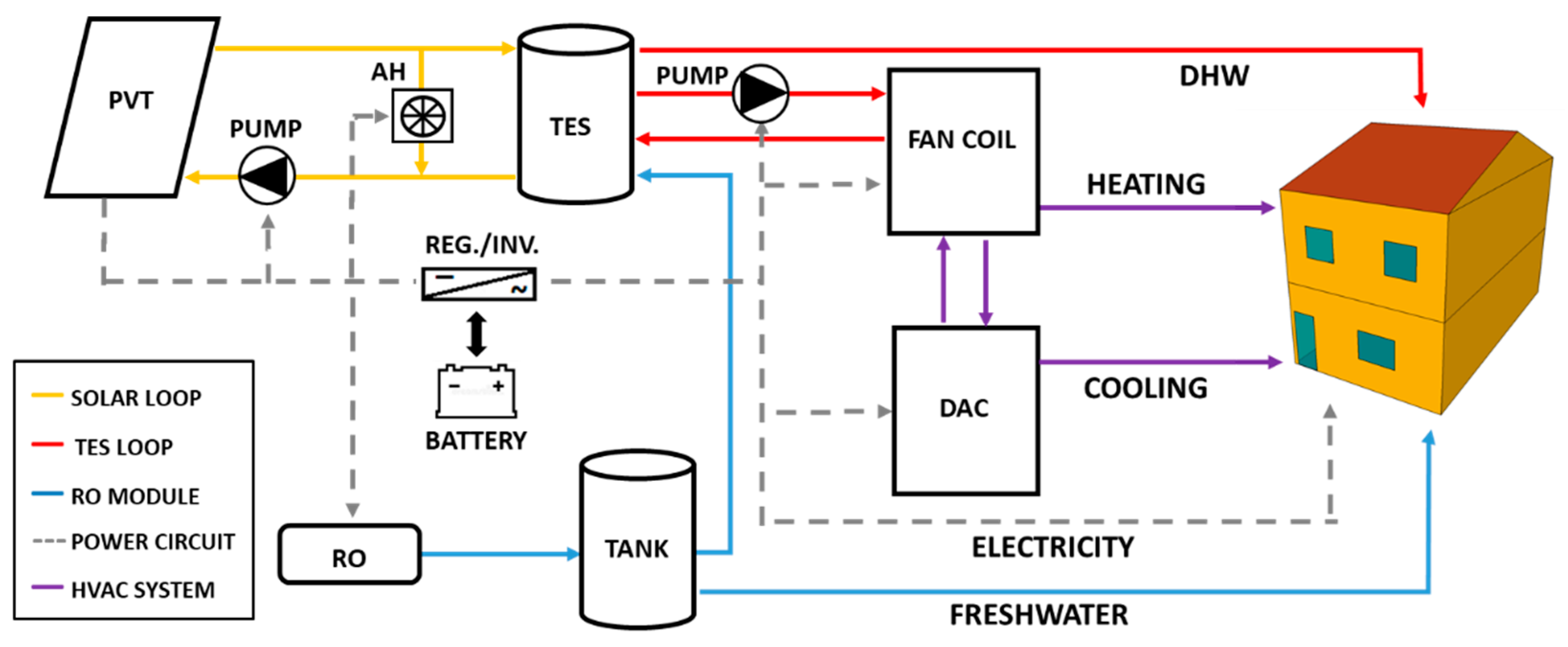
2.1. System Layout

The proposed approach is adapted from the polygeneration system designed by Gesteira et al. [39] (Figure 1). Here, the novelty is the electrical storage replacing the grid to avoid grid dependence and converting it to an off-grid system. Moreover, a new regulator/inverter for monitoring the battery state of charge was added. The solar and TES loops, RO module, and HVAC system are described in more detail in Ref. [39]; therefore, in this work, only the new off-grid power circuit is deeply reported.
The PVT collectors convert solar irradiation into electrical and thermal energy with a fixed slope of 35° (no tracking). The solar collector fluid is a mixture of water/glycol (60/40). The thermal energy storage consists of a fluid-filled sensible vertically stratified (four nodes) energy storage tank with a heat exchanger inside. An air heater (AH) prevents fluid overheating by dissipating heat with a capacity of 20 kW. The TES supplies the HVAC system and the DHW at 45 °C. The RO device consumes 110 W and produces 35 kg/h of freshwater. The freshwater is stored in a tank of 1.0 m³. In the winter season, heating is provided for the building through a fan coil. During summertime, the thermal energy drives a DAC system and provides cooling.
Regarding the power circuit, the electricity consumption consists of the building’s electric demand and the system power load (pumps, fans, etc.). The PVT collector’s power is sent to a regulator/inverter with peak-power tracking. Two power-conditioning devices are needed in PV power systems coupled with ES. The first is a regulator, which distributes DC power from the solar array to and from a battery. If the battery is fully charged, excess energy is dumped. The second component is the inverter, which converts the DC power to AC and sends it to the load. Although batteries are expensive and require notable maintenance [41], an economic analysis was not performed. However, they can be economically competitive for isolated dwellings for which the cost of connection to the grid would be high [42].

2.2. System Model

The TRNSYS environment (version 18) [40] was used to model and dynamically simulate the proposed system (PS). The software’s built-in library provided all components used to develop the system. Some of them are user-defined, such as calculators, controllers, and data readers set by the authors. Others are required to provide the results, such as integrators and plotters. Here, a detailed description of the regulator/inverter, the battery storage, and the energy and environmental models are reported. The other components’ descriptions are available in TRNSYS’s component mathematical reference [40]. Table 1 presents the parameters of the novel power circuit of the PS.

2.2.1. Regulator/Inverter Model

Type 48 models both the regulator and inverter with peak-power tracking. It is a power-conditioning device that distributes DC power from the solar array to and from a battery bank. It converts the input power to an AC output signal waveform [43] and sends it to the load. It also monitors the battery’s state of charge (SOC). If the SOC is between the high limit on the state of charge (HSOC) and the low limit on the state of charge (LSOC), the battery can discharge (when the power production, Pprod, is lower than the power demand, Ptot,dem) or charge (when Pprod is greater than Ptot,dem). The priority for the power output is to match the electricity demand. It also monitors if the SOC is lower than LSOC and no further discharging is allowed or if it is higher than HSOC, the excess power is dumped. A detailed description of subroutines of such additional controls is reported by Calise et al. [35]. It is important to note that power exchange with the electric grid is not admitted.

2.2.2. Battery Model

A lead-acid storage battery (Type 47) operates with the solar array and the power-conditioning components. It specifies how the battery SOC varies over time, given the rate of charge or discharge. This model is based on a simple energy balance of the battery [44]. The battery mathematical model is based on Shepherd equations, which describe the battery charge or discharge [40]. The battery discharge equation (I < 0) is given by:
V = e q d g d i s H + I r q d ( 1 + m d i s H Q d i s Q m H )
And the battery charge equation (I > 0) is given by:
V = e q c g c h a H + I r q c ( 1 + m c h a H Q c h a Q m H )
The maximum charging and minimum discharging voltages are limited to extend the battery lifetime. The voltage limit on discharge is calculated from the:
V d i s = e d i s | I | r d i s
The variation of the battery charge is calculated as follows:
d Q d t = { I                     i f   I < 0   I . η c h a           i f   I > 0   }

2.2.3. Energy and Environmental Models

The energy performance of the PS is evaluated by the primary energy saving (PES) index. The PS considers the demands not attended to by the polygeneration system. A reference system (RS) compares all demands provided by traditional energy sources. The RS consists of an electric cooling system (ECS) with a coefficient of performance, COPECS, of 2.6, and a natural gas boiler (GB) with a thermal efficiency, ηth, of 0.92 [45]. The Spanish electric grid efficiency was taken from IDAE [46], ηel = 0.42.
The PES and its ratio (PESR) are calculated as shown in Equations (5) and (6):
PES = P E R S P E P S
PES r = P E S     P E R S
PE RS = ( P b u i l d ,   d e m   + P s y s t ,   d e m η e l + Q D H W ,   d e m   + Q h e a t ,   d e m η t h + Q c o o l ,   d e m C O P E C S · η e l   ) R S
PE PS = ( P g r i d , a u x η e l + Q D H W ,   a u x     + Q h e a t ,   a u x η t h + Q c o o l ,   a u x C O P E C S   · η e l   ) P S
Pgrid,aux is the electricity withdrawn from the grid, and QDHW,aux, Qheat,aux, and Qcool,aux are the thermal demands supplied by a GB and an ECS.
Following the same method, the CO2 saving was used as the environmental analysis, as shown in Equations (9) and (10):
CO 2     C O 2 R S C O 2 P S
CO 2 r     C O 2 C O 2 R S
CO 2 RS   [ ( P b u i l d ,   d e m + P s y s t ,   d e m ) · f C O 2 , E E + ( Q D H W ,   d e m + Q h e a t ,   d e m ) · f C O 2 , N G + ( Q c o o l ,   d e m C O P E C S   ) · f C O 2 , E E ] R S
CO 2 PS   [ ( P g r i d , a u x ) · f C O 2 , E E + ( Q D H W ,   a u x + Q h e a t ,   a u x ) · f C O 2 , N G + ( Q c o o l ,   a u x C O P E C S   ) · f C O 2 , E E ] P S
The Spanish emission factor for natural gas,   f C O 2 , N G , is 0.25 kgCO2/kWh [46], and for the grid,   f C O 2 , E E , it is 0.19 kgCO2/kWh [47].

3. Results and Discussion

The residential building used during the simulation is described in detail by Ref. [48]. Table 2 summarizes all the information regarding the climate zone and the building. In this paper, the authors propose a novel polygeneration system for the same case study. It supplies electricity, heating, cooling, DHW, and freshwater for a residential dwelling located in Almeria, Spain.
The simulation was performed based on one year with a 5-min time step. Firstly, a parametric study was performed to investigate the behavior of the polygeneration system developed in Ref. [39] when coupled with a battery bank. Then, a design optimization was done to determine the system’s off-grid optimal setup. For that reason, the number of PVT collectors and batteries was simultaneously optimized. Finally, the optimal system behavior is shown based on typical-day temperature and energy profiles. The yearly results showed the main performance metrics.

3.1. Design of the Storage Capacity

Table 3 comprehends the solar generation parameters of the polygeneration system developed by Ref. [39]. Here, a parametric analysis was conducted to investigate the behavior of this system when coupled with a battery bank. The number of batteries (Nbatt) varied from 1 to 20. The off-grid configuration is obtained when the PESr and CO2r achieve their maximum, and the Pgrid,aux is no longer required by the system. As seen in Figure 2, the addition of batteries to the already developed system solely cannot convert it into an off-grid facility.
An annual electricity autonomy is a primary goal. However, Pgrid,aux was not able to achieve less than 500 kWh per year based only on the batteries addition. It can also be seen by the energy and environmental analysis, which achieved a maximum of 89.4% and 92.0% of PESr and CO2r, respectively, due to the grid electricity consumption. It is worth noting that selling back electricity to the grid was neglected.

3.2. Design Optimization

To achieve 100% electricity autonomy, an optimization analysis was performed. The TRNOPT plug-in included in the TRNSYS package links the optimization algorithm and the simulation model. This tool uses the algorithms included in the GENOPT package developed by Lawrence Berkeley National Laboratory [49] to perform complex mathematical operations and optimize the system. In particular, the generalized search method was used as this technique avoids the calculation of partial derivatives. The Hooke–Jeeves [50] modified algorithm was selected. The structure of this algorithm avoids the achievement of local minimum points and considers the TRNSYS simulation for approximating the objective function. This optimization method provides the optimum value in a relatively low number of iterations.
The optimization was conducted considering the number of PVT collectors and batteries to achieve an off-grid capable setup. Moreover, the PES and CO2 ratios were selected as optimization objective functions. As they are similar, the results coincided for both parameters. Figure 3 shows the optimized variables as a function of iterations. The optimization process converged in more than 100 simulations. The optimization results are consistent with the ones obtained by the parametric study. The optimum number of PVT collectors was 30 due to roof limitation. Regarding the number of batteries, the optimum value was 22. Moreover, it is worth noting that the optimization algorithm restricted the lower value for both variables to 1, and the maximum number of batteries was not limited.

3.3. Daily Analysis: A Typical Summer Day

A daily result for the summer season is presented next. As a representative day, 6 August was chosen. Figure 4 displays the profile of the main parameters for this typical day. The power produced by the PVT collectors (PPVT) follows the increase in solar radiation. PPVT starts to increase at 6:30, meets its maximum at 12:30 (4197 W), and then decreases until 20:00. The battery power (Pbatt) meets the electric demand (Pload) from 0:00 to 9:00 and from 18:30 to 24:00, which coincides with the overnight period or deficient power production. The excess power produced during the daylight is dumped (Pdump) between 13:30 and 19:00 as the battery SOC achieves 100%. No electricity is withdrawn from the grid (Pgrid) during the day. The minimum SOC found was around 80%.

3.4. Daily Analysis: A Typical Winter Day

As a winter day, 24 January was selected. Figure 5 shows its main parameters. Here, the sunlight period is shorter. PPVT increases at 8:30, meets its maximum at 13:30 (4292 W), and then decreases until 18:00, four hours less than in the summertime. The battery is fully charged between 9:00 and 12:00. Pbatt supplies Pload from 0:00 to 9:00 and from 18:00 to 24:00, coinciding with the overnight time. Pdump occurs between 13:30 and 19:00 as the battery SOC achieves 100%. Pgrid remains null throughout the day. The minimum SOC found was greater than the summer case and was around 85%.

3.5. Yearly Results

The state of charge of a lead-acid battery denotes the actual battery capacity as a function of the rated capacity. It can vary between 0% to 100%. In this application, the SOC can go down to 30% to minimize the number of batteries during the optimization process. Therefore, the battery is recharged when the SOC reaches 30%. SOC over 100% is not permitted. Thus, electricity is dumped whenever 100% SOC is achieved.
The annual SOC profile found in this study is shown in Figure 6. It is important to note that the SOC affects the safe operation, aging, and degradation of the batteries [51]. The minimum SOC of 30% was achieved for only a few hours in the year, from 8359 h to 8362 h and from 8408 h to 8409 h.
The annual results are summarized in Table 4. Here, Pprod is the PPVT minus the regulator/inverter losses due to its inefficiency during the DC to AC conversion (4%). The total useful power production (Ptot) is the Pprod minus the Pdump by the system when the excess power cannot be delivered to the battery because it is fully charged. The off-grid system fully attends to the annual electricity demand during the simulation.
The total useful heat production (Qtot) is the PVT heat generation (QPVT) minus the heat released by the AH (QAH) and the heat dissipated to the environment (Qloss). The energy dissipated by the air heater is around 76.7%, and the thermal losses correspond to 8% of QPVT. The air heater dissipates much energy as the system prioritizes electricity production. Moreover, Qtot is used for attending QDHW,dem, Qheat,dem, and Qcool,dem. However, as the DAC thermal COP is 0.42, the thermal energy required by the DAC regenerator (3750 kWh/yr) is much higher than Qcool,dem (1450 kWh/yr). Nevertheless, the annual thermal demand is also fully supplied by the system.
The previous work [39] simulated a polygeneration system consisting of 17 (27.2 m2) PVT collectors connected to the national electric grid. An annual near-zero electricity balance was assumed for the electricity withdrawn and sold back to the grid. However, according to the parametric study presented here, this system is not suitable for conversion to an off-grid facility. The addition of lead-acid battery storage on it was not able to provide annual electricity autonomy from the grid.
Consequently, a design optimization was performed to determine a novel polygeneration system setup that is fully independent of the grid. For that case, the number of PVT collectors was increased to 30 (48 m2), and 22 (48.4 kWh) batteries were established by the optimization algorithm. In particular, the constraints were the roof availability (50 m2) and the minimum SOC, affecting the PVT generation and the storage bank size, respectively.

4. Conclusions

This paper investigated a novel off-grid polygeneration system for residential applications. The proposed system integrates PVT collectors, RO, and DAC coupled with lead-acid batteries. The system was simulated for a single-family townhouse in Spain to meet the demands of electricity, heating, cooling, domestic hot water, and freshwater. The system can be applied to isolated areas with mild relative humidity and temperature, which makes the operation of a DAC possible. The system’s layout was dynamically simulated in the TRNSYS environment on an hourly and yearly basis. Design optimization of the system was done under different numbers of PVT collectors and batteries to achieve the optimal off-grid system structure. The main findings are summarized in the following:
  • The introduction of batteries to the already developed on-grid system solely cannot convert it into an off-grid plant. Indeed, the number of PVT collectors and the number of batteries must also be considered.
  • The optimal off-grid system configuration for Almería was obtained for 30 PVT collectors and 22 batteries. This optimization pursued null electricity withdrawn from the grid. For that reason, an energy and environmental approach was used, neglecting the system’s economic feasibility.
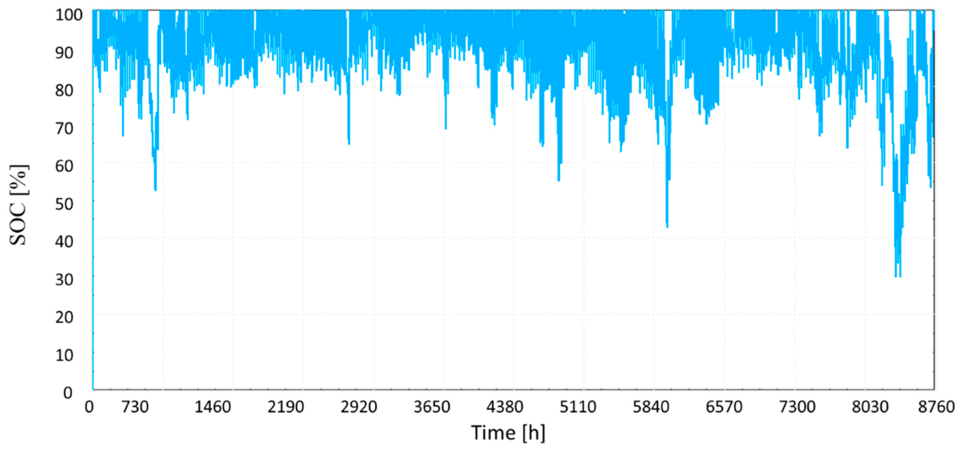
  • The minimum battery SOC was defined as 30%, which may decrease the battery lifespan. However, the yearly results showed that the SOC achieved its minimum only for a few hours during the year. Lithium battery would be an interesting choice for avoiding lifespan issues but with higher costs.
  • The energy released by the air heater was around 77% of the generated heat due to an electricity generation priority. The excess heat may be reduced with the addition of PV panels instead of increasing PVT collectors or used in other thermal applications.
  • High PES and CO2 savings were found, and all demands were fully attended.
To sum up, the developed polygeneration system is replicable for other cities, mainly those disconnected from the grid. It can be an interesting option for meeting the energy demands using RES. Future works should investigate the economic feasibility of the capital cost of new and second-life batteries if the grid is not available or determine which system is more attractive if the grid is available, considering the electricity purchase tariff.

Author Contributions

Conceptualization, J.U.; methodology, L.G.G.; formal analysis, L.G.G.; investigation, L.G.G.; resources, J.U.; data curation, L.G.G.; writing—original draft preparation, L.G.G.; writing—review and editing, L.G.G., J.U., and N.D.-O.; supervision, J.U. All authors have read and agreed to the published version of the manuscript.

Funding

This research received no external funding.

Institutional Review Board Statement

Not applicable.

Informed Consent Statement

Not applicable.

Data Availability Statement

Not applicable.

Conflicts of Interest

The authors declare no conflict of interest.

Nomenclature

Aarea (m2)
COPcoefficient of performance
eopen circuit voltages (V)
gcoefficients of H in voltage-current-state of charge formulas (V)
Hcomplement to 1 of fractional state of charge
HSOChigh limit on the fractional state of charge
Ielectric current (A)
LSOClow limit on the fractional state of charge
mcell-type parameter for shapes of the battery I-V-Q characteristics
Nnumber
Pelectric power (kW)
PEprimary energy (kWh/year)
PESprimary energy saving (-)
Qbattery electrical charge or thermal power (Ah or kW)
rinternal resistance (Ω)
SOCstate of charge
ttime (h)
Vvolume or voltage (m3 or V)
vmass flow rate (kg s−1)
Greek Symbols
ηefficiency (-)
Subscripts
auxauxiliary
battbattery
buildreferred to the building
capcapacity
chacharge
coolcooling
demdemand
disdischarge
dumpelectricity dumped
EEelectricity
elelectric
fcollector fluid
gridreferred to the electric grid
heatheating
invinverter
loadreferred to the energy load
lossreferred to the energy loss
NGnatural gas
qcfull charge when charging
qdfull charge when discharging
prodproduction
Rratio
systreferred to the system
ththermal
tottotal
Abbreviations and acronyms
ACalternating current
AHair heater
DACdesiccant air conditioning
DCdirect current
DHWdomestic hot water
ESelectrical storage
ECSelectric cooling system
FWfreshwater
GBgas boiler
HVACheating, ventilation, and air conditioning
NZEBnearly zero-energy building
PSproposed system
PVphotovoltaic panel
PVTphotovoltaic/thermal collector
ROreverse osmosis
RSreference system
RESrenewable energy sources
TRNSYSTRansient SYstem Simulation tool
TESthermal energy storage
WTwind turbine

References

  1. Costa, A.; Keane, M.M.; Torrens, J.I.; Corry, E. Building Operation and Energy Performance: Monitoring, Analysis and Optimisation Toolkit. Appl. Energy 2013, 101, 310–316. [Google Scholar] [CrossRef]
  2. International Energy Agency. Energy and Climate Change: World Energy Outlook Special Report; IEA: Paris, France, 2015. [Google Scholar]
  3. European Commission. Communication from the Commission to the European Parliament, the Council, the European Economic and Social Committee and the Committee of the Regions: An EU Strategy on Heating and Cooling; European Commission: Brussels, Belgium, 2016. [Google Scholar]
  4. European Commission. Commission Recommendation (EU) 2016/1318: On Guidelines for the Promotion of Nearly Zero-Energy Buildings and Best Practices to Ensure That, by 2020, All New Buildings Are Nearly Zero-Energy Buildings; Official Journal of the European Union: Brussels, Belgium, 2016; p. 12. [Google Scholar]
  5. Calise, F.; de Notaristefani di Vastogirardi, G.; Dentice d’Accadia, M.; Vicidomini, M. Simulation of Polygeneration Systems. Energy 2018, 163, 290–337. [Google Scholar] [CrossRef]
  6. Calise, F.; Cappiello, F.L.; Dentice d’Accadia, M.; Vicidomini, M. Thermo-Economic Analysis of Hybrid Solar-Geothermal Polygeneration Plants in Different Configurations. Energies 2020, 13, 2391. [Google Scholar] [CrossRef]
  7. Olabi, A.G. Renewable Energy and Energy Storage Systems. Energy 2017, 136, 1–6. [Google Scholar] [CrossRef]
  8. MendezQuezada, V.H.; RivierAbbad, J.; GomezSanRoman, T. Assessment of Energy Distribution Losses for Increasing Penetration of Distributed Generation. IEEE Trans. Power Syst. 2006, 21, 533–540. [Google Scholar] [CrossRef]
  9. Chen, Y.; Liu, Y.; Wang, Y.; Wang, D.; Dong, Y. The Research on Solar Photovoltaic Direct-Driven Air Conditioning System in Hot-Humid Regions. Procedia Eng. 2017, 205, 1523–1528. [Google Scholar] [CrossRef]
  10. Yekini Suberu, M.; Wazir Mustafa, M.; Bashir, N. Energy Storage Systems for Renewable Energy Power Sector Integration and Mitigation of Intermittency. Renew. Sustain. Energy Rev. 2014, 35, 499–514. [Google Scholar] [CrossRef]
  11. Liu, T.; Yang, Z.; Duan, Y.; Hu, S. Techno-Economic Assessment of Hydrogen Integrated into Electrical/Thermal Energy Storage in PV+ Wind System Devoting to High Reliability. Energy Convers. Manag. 2022, 268, 116067. [Google Scholar] [CrossRef]
  12. Fan, M.; Lu, S. Benefit Analysis and Preliminary Decision-Making of Electrical and Thermal Energy Storage in the Regional Integrated Energy System. J. Energy Storage 2022, 55, 105816. [Google Scholar] [CrossRef]
  13. Chen, H.; Cong, T.N.; Yang, W.; Tan, C.; Li, Y.; Ding, Y. Progress in Electrical Energy Storage System: A Critical Review. Prog. Nat. Sci. 2009, 19, 291–312. [Google Scholar] [CrossRef]
  14. Beaudin, M.; Zareipour, H.; Schellenberglabe, A.; Rosehart, W. Energy Storage for Mitigating the Variability of Renewable Electricity Sources: An Updated Review. Energy Sustain. Dev. 2010, 14, 302–314. [Google Scholar] [CrossRef]
  15. May, G.J.; Davidson, A.; Monahov, B. Lead Batteries for Utility Energy Storage: A Review. J. Energy Storage 2018, 15, 145–157. [Google Scholar] [CrossRef]
  16. Hazelton, J.; Bruce, A.; MacGill, I. A Review of the Potential Benefits and Risks of Photovoltaic Hybrid Mini-Grid Systems. Renew. Energy 2014, 67, 222–229. [Google Scholar] [CrossRef]
  17. Wollny, M.; Tapanlis, S. Hybrid Backup Power Solutions for Unstable Grids. In Proceedings of the 4th European Conference on PV-Hybrids and Mini-Grids, Glyfada, Greece, 29–30 May 2008. [Google Scholar]
  18. Dekker, J.; Nthontho, M.; Chowdhury, S. Economic Analysis of PV/ Diesel Hybrid Power Systems in Different Climatic Zones of South Africa. Int. J. Electr. Power Energy Syst. 2012, 40, 104–112. [Google Scholar] [CrossRef]
  19. Schroeter, A.; Martin, S. Profitable and Affordable Energy Services for Remote Areas in Lao PDR: Private-Public Partnership as Mutual Leverage for Hybrid Village Grids in Areas of the National Grid. In Proceedings of the 4th European Conference on PV-Hybrids and Mini-Grids, Glyfada, Greece, 29–30 May 2008. [Google Scholar]
  20. Wiser, R.; Millstein, D.; Mai, T.; Macknick, J.; Carpenter, A.; Cohen, S.; Cole, W.; Frew, B.; Heath, G. The Environmental and Public Health Benefits of Achieving High Penetrations of Solar Energy in the United States. Energy 2016, 113, 472–486. [Google Scholar] [CrossRef] [Green Version]
  21. Goldsworthy, M.J. Building Thermal Design for Solar Photovoltaic Air-Conditioning in Australian Climates. Energy Build. 2017, 135, 176–186. [Google Scholar] [CrossRef]
  22. Li, Y.; Zhang, G.; Lv, G.Z.; Zhang, A.N.; Wang, R.Z. Performance Study of a Solar Photovoltaic Air Conditioner in the Hot Summer and Cold Winter Zone. Sol. Energy 2015, 117, 167–179. [Google Scholar] [CrossRef]
  23. Vick, B.D.; Neal, B.A. Analysis of Off-Grid Hybrid Wind Turbine/Solar PV Water Pumping Systems. Sol. Energy 2012, 86, 1197–1207. [Google Scholar] [CrossRef] [Green Version]
  24. Alex, Z.; Clark, A.; Cheung, W.; Zou, L.; Kleissl, J. Minimizing the Lead-Acid Battery Bank Capacity through a Solar PV - Wind Turbine Hybrid System for a High-Altitude Village in the Nepal Himalayas. Energy Procedia 2014, 57, 1516–1525. [Google Scholar] [CrossRef] [Green Version]
  25. Nookuea, W.; Campana, P.E.; Yan, J. Evaluation of Solar PV and Wind Alternatives for Self Renewable Energy Supply: Case Study of Shrimp Cultivation. Energy Procedia 2016, 88, 462–469. [Google Scholar] [CrossRef]
  26. Buonomano, A.; Calise, F.; Vicidomini, M.; Dentice d’Accadia. A Hybrid Renewable System Based on Wind and Solar Energy Coupled with an Electrical Storage: Dynamic Simulation and Economic Assessment. Energy 2018, 155, 174–189. [Google Scholar] [CrossRef]
  27. Rehman, S.; Al-Hadhrami, L.M. Study of a Solar PV–Diesel–Battery Hybrid Power System for a Remotely Located Population near Rafha, Saudi Arabia. Energy 2010, 35, 4986–4995. [Google Scholar] [CrossRef]
  28. Chabaud, A.; Eynard, J.; Grieu, S. A New Approach to Energy Resources Management in a Grid-Connected Building Equipped with Energy Production and Storage Systems: A Case Study in the South of France. Energy Build. 2015, 99, 9–31. [Google Scholar] [CrossRef]
  29. Koh, S.L.; Lim, Y.S. Methodology for Assessing Viability of Energy Storage System for Buildings. Energy 2016, 101, 519–531. [Google Scholar] [CrossRef]
  30. Stadler, M.; Kloess, M.; Groissböck, M.; Cardoso, G.; Sharma, R.; Bozchalui, M.C.; Marnay, C. Electric Storage in California’s Commercial Buildings. Appl. Energy 2013, 104, 711–722. [Google Scholar] [CrossRef] [Green Version]
  31. Zhang, C.; Wei, Y.-L.; Cao, P.-F.; Lin, M.-C. Energy Storage System: Current Studies on Batteries and Power Condition System. Renew. Sustain. Energy Rev. 2018, 82, 3091–3106. [Google Scholar] [CrossRef]
  32. Comodi, G.; Giantomassi, A.; Severini, M.; Squartini, S.; Ferracuti, F.; Fonti, A.; Nardi Cesarini, D.; Morodo, M.; Polonara, F. Multi-Apartment Residential Microgrid with Electrical and Thermal Storage Devices: Experimental Analysis and Simulation of Energy Management Strategies. Appl. Energy 2015, 137, 854–866. [Google Scholar] [CrossRef]
  33. Singh, S.; Singh, M.; Kaushik, S.C. Feasibility Study of an Islanded Microgrid in Rural Area Consisting of PV, Wind, Biomass and Battery Energy Storage System. Energy Convers. Manag. 2016, 128, 178–190. [Google Scholar] [CrossRef]
  34. Destro, N.; Benato, A.; Stoppato, A.; Mirandola, A. Components Design and Daily Operation Optimization of a Hybrid System with Energy Storages. Energy 2016, 117, 569–577. [Google Scholar] [CrossRef]
  35. Calise, F.; Figaj, R.D.; Vanoli, L. A Novel Polygeneration System Integrating Photovoltaic/Thermal Collectors, Solar Assisted Heat Pump, Adsorption Chiller and Electrical Energy Storage: Dynamic and Energy-Economic Analysis. Energy Convers. Manag. 2017, 149, 798–814. [Google Scholar] [CrossRef]
  36. Żołądek, M.; Kafetzis, A.; Figaj, R.; Panopoulos, K. Energy-Economic Assessment of Islanded Microgrid with Wind Turbine, Photovoltaic Field, Wood Gasifier, Battery, and Hydrogen Energy Storage. Sustainability 2022, 14, 12470. [Google Scholar] [CrossRef]
  37. Cappiello, F.L.; Cimmino, L.; Napolitano, M.; Vicidomini, M. Thermoeconomic Analysis of Biomethane Production Plants: A Dynamic Approach. Sustainability 2022, 14, 5744. [Google Scholar] [CrossRef]
  38. Kim, H.; Jung, Y.; Oh, J.; Cho, H.; Heo, J.; Lee, H. Development and Evaluation of an Integrated Operation Strategy for a Poly-Generation System with Electrical and Thermal Storage Systems. Energy Convers. Manag. 2022, 256, 115384. [Google Scholar] [CrossRef]
  39. Gesteira, L.G.; Uche, J. A Novel Polygeneration System Based on a Solar-Assisted Desiccant Cooling System for Residential Buildings: An Energy and Environmental Analysis. Sustainability 2022, 14, 3449. [Google Scholar] [CrossRef]
  40. TRNSYS: A Transient System Simulation Program; Solar Energy Laboratory, University of Wisconsin: Madison, WI, USA, 2006.
  41. Gómez Melgar, S.; Sánchez Cordero, A.; Videras Rodríguez, M.; Andújar Márquez, J.M. Matching Energy Consumption and Photovoltaic Production in a Retrofitted Dwelling in Subtropical Climate without a Backup System. Energies 2020, 13, 6026. [Google Scholar] [CrossRef]
  42. Lubello, P.; Pasqui, M.; Mati, A.; Carcasci, C. Assessment of Hydrogen-Based Long Term Electrical Energy Storage in Residential Energy Systems. Smart Energy 2022, 8, 100088. [Google Scholar] [CrossRef]
  43. Havrlík, M.; Libra, M.; Poulek, V.; Kouřím, P. Analysis of Output Signal Distortion of Galvanic Isolation Circuits for Monitoring the Mains Voltage Waveform. Sensors 2022, 22, 7769. [Google Scholar] [CrossRef]
  44. Souza, R.P.S. Dynamic Simulation and Optimization of an Off-Grid Solar Photovoltaic Driven Drinking Fountain with Battery Storage. Int. J. Smart Grid Sustain. Energy Technol. 2021, 4, 13. [Google Scholar] [CrossRef]
  45. Spanish Ministry of Development. Updating of the Energy Saving Document DB-HE of the Technical Building Code. 2019. Available online: https://www.codigotecnico.org/pdf/Documentos/HE/DBHE.pdf (accessed on 1 October 2022).
  46. Instituto para la Diversificación y Ahorro de la Energia (IDAE). CO2 Emission Factors and Primary Energy Coefficients for Different Final Energy Sources Consumed in the Building Sector in Spain; IDAE: Madrid, Spain, 2014. [Google Scholar]
  47. Red Eléctrica Española (REE). CO2 Emissions of Electricity Generation in Spain; REE: Madrid, Spain, 2021. [Google Scholar]
  48. Gesteira, L.G.; Uche, J.; de Oliveira Rodrigues, L.K. Residential Sector Energy Demand Estimation for a Single-Family Dwelling: Dynamic Simulation and Energy Analysis. J. Sustain. Dev. Energy Water Environ. Syst. 2021, 9, 1080358. [Google Scholar] [CrossRef]
  49. Wetter, J.F. A generic optimization program. In Proceedings of the 7th IBPSA Conference, Rio de Janeiro, Brazil, 13–15 August 2001. [Google Scholar]
  50. Hooke, R.; Jeeves, T.A. “Direct search” solution of numerical and statistical problems. J. Assoc. Comput. Mach. 1961, 8, 17. [Google Scholar] [CrossRef]
  51. Vetter, J.; Novák, P.; Wagner, M.R.; Veit, C.; Möller, K.-C.; Besenhard, J.O.; Winter, M.; Wohlfahrt-Mehrens, M.; Vogler, C.; Hammouche, A. Ageing Mechanisms in Lithium-Ion Batteries. J. Power Sources 2005, 147, 269–281. [Google Scholar] [CrossRef]
Figure 1. Polygeneration system layout (adapted from Ref. [39]).
Sustainability 14 15784 g001
Figure 2. Parametric analysis: performance parameters and grid power, number of batteries.
Sustainability 14 15784 g002
Figure 3. Parametric analysis: performance parameters and grid power, number of batteries.
Sustainability 14 15784 g003
Figure 4. Summer day profile.
Sustainability 14 15784 g004
Figure 5. Winter day profile.
Sustainability 14 15784 g005
Figure 6. Battery annual SOC profile.
Sustainability 14 15784 g006
Table 1. Main design and operation parameters of the power circuit.
TypeParameterSymbolValueUnit
Regulator/inverterEfficiencyηi0.96
High limit on fractional state of charge HSOC1
Low limit on fractional state of chargeLSOC0.3
Inverter output power capacityPinv4kW
BatteryCapacityBcap2.2kWh
VoltagePbatt12V
Table 2. Main climate and building parameters of the case study.
Climate Zone
LocationAlmeria
Latitude36°50′ N
Altitude above sea level (m)0
Annual average outdoor temperature (°C)18.4
Horizontal global solar radiation (kWh/year)1829
Average temperature of tap water (°C)15.7
Building description
TypeSingle-family, semi-detached house
Number of occupants4
Total conditioned area (m2)110
Total area (m2)165
No. of floors2 + attic
Height per floor (m)3
Total building height (m)7.5
Total volume (m3)371.3
Window-to-wall ratio for north façade (%)10
Window-to-wall ratio for south façade (%)15
Building envelope transmittances
External wall (W/m2·K)0.5
External roof (W/m2·K)0.47
Floor (W/m2·K)0.5
Door (W/m2·K)2.2
Window (W/m2·K)2.6
Building usage profile
Setpoint temperature (°C)Heating season1700:00–08:00
2008:00–24:00
Cooling season2700:00–08:00
-08:00–16:00
2516:00–24:00
Occupancy load (W/m2)Weekday3.5100:00–08:00
0.8808:00–16:00
1.7616:00–24:00
Weekend3.5100:00–24:00
Lighting load/equipment load (W/m2)1.7600:00-01:00
0.4401:00-08:00
1.3208:00-19:00
2.219:00-20:00
4.420:00-24:00
Ventilation rate (1/h)Heating season0.400:00–24:00
Cooling season401:00–09:00
0.409:00–01:00
Infiltration rate (1/h)0.4500:00-24:00
Daily DHW demand per person (l/day·person)28
Table 3. Solar loop design parameters [39].
TypeParameterSymbolValueUnit
PVTAreaAPVT27.2 m2
InverterEfficiencyηinv0.9
Air heaterHeat dissipation capacityQAH20kW
Solar pumpNominal flow rate per PVT areavf /APVT50kg/h·m2
TESTES volume/PVT areaVTES/APVT0.1m3/m2
Table 4. Yearly results.
ParameterSymbolValueUnit
Building electricity demandPbuild,dem3866kWh/yr [48]
System electricity demandPsyst,dem2167kWh/yr
Total electricity demandPtot,dem6033kWh/yr
DHW demandmDHW,dem41m3/yr [48]
Freshwater demandmFW,dem110m3/yr [48]
Total water demandmtot,dem151m3/yr
DHW thermal demandQDHW,dem1260kWh/yr
Building cooling demandQcool,dem1450kWh/yr [48]
Building heating demandQheat,dem941kWh/yr [48]
Total thermal demandQtot,dem3651kWh/yr
Power productionPprod10,018kWh/yr
Power dumpedPdump3741kWh/yr
Total useful power productionPtot6277kWh/yr
PVT heat productionQPVT39,876kWh/yr
Air heater dissipationQAH30,599kWh/yr
Heat lossesQloss3234kWh/yr
Total useful heat productionQtot6043kWh/yr
RO freshwater productionmRO151m3/yr
PVT total efficiencyηPVT0.55
DAC thermal COPCOPDAC0.42
Primary energy savingPESkWh12,893
CO2 savingCO2kgCO21380
Publisher’s Note: MDPI stays neutral with regard to jurisdictional claims in published maps and institutional affiliations.

