Article

Optimization of Hydrokinetic Swept Blades

by
Miriam L. A. Gemaque
1,
Jerson R. P. Vaz
1,* and
Osvaldo R. Saavedra
2
1
Graduate Program in Mechanical Engineering, Institute of Technology, Federal University of Pará, Av. Augusto Correa, 1, Belém 66075-900, PA, Brazil
2
National Institute of Science and Technology in Ocean and Fluvial Energies, Federal University of Maranhão, Av. dos Portugueses, 1966, São Luís 65080-805, MA, Brazil
*
Author to whom correspondence should be addressed.
Sustainability 2022, 14(21), 13968; https://doi.org/10.3390/su142113968
Submission received: 31 August 2022 / Revised: 28 September 2022 / Accepted: 5 October 2022 / Published: 27 October 2022
(This article belongs to the Special Issue Renewable Energy and Future Developments)

Abstract

:
The hydrokinetic turbine is used worldwide for electrical generation purposes, as such a technology may strongly reduce environmental impact. Turbines designed using backward swept blades can significantly reduce the axial load, being relevant for hydro turbines. However, few works have been conducted in the literature in this regard. For the case of hydrokinetic rotors, backward swept blades are still a challenge, as the authors are unaware of any optimization procedures available, making this paper relevant for the current state of the art. Thus, the present work develops a new optimization procedure applied to hydrokinetic turbine swept blades, with the main objective being the design of blades with reduced axial load on the rotor and possibly a reduction in the cavitation. The proposed method consists of an extension of the blade element momentum theory (BEMT) to the case of backward swept blades through a radial transformation function. The method has low computational cost and easy implementation. Once it is based on the BEMT, it presents good agreement when compared to experimental data. As a result, the sweep heavily affects the chord and twist angle distributions along the blade, increasing the turbine torque and power coefficient. In the case of the torque, it can be increased by about 18%. Additionally, even though the bound circulation demonstrates a strong change for swept rotors, Prandtl’s tip loss seems to be not sensitive to the sweep effect, and alternative models are needed.

1. Introduction

It is well known that hydrokinetic turbine blades are responsible for converting the kinetic energy transported by rivers into electrical energy. As reported by Rio Vaz et al. [1], hydrokinetic rotors are similar to wind ones and their efficiency, without a doubt, is limited to 59.3% [2]. There are currently different types of turbines, including those with backward swept blades, which can significantly reduce the axial load. However, regarding the optimization of hydrokinetic blades, only a few studies have been conducted in the literature. In this context, a novel approach for the optimization of hydrokinetic turbines with backward swept blades is proposed in this paper. The optimization procedure is based on the blade element momentum theory (BEMT), which is extended to analyze swept blades. In this case, a change is made on the radial coordinate of the rotor, in which a transformation using a mathematical function dependent on the local swept angle is employed. Such a transformation modifies the aerodynamic shape of the turbine blade, through chord and twist angle distributions.
In the current literature, some works have been proposed for optimizing hydrokinetic blades, but applied to rotors with straight blades only. For example, Silva et al. [3] showed a model to design hydrokinetic blades considering cavitation. In their work, a methodology for cavitation prevention was employed. Their results were compared with data from hydrokinetic turbines designed using classical Glauert’s optimization, demonstrating good performance. In the work of Muratoglu et al. [4], an optimization of hydrokinetic turbines using differential evolution algorithms was studied. The analysis was developed specifically for stall-regulated turbines, considering high hydrodynamic forces, cavitation, blade tip loss and optimal stall behavior. That paper described a parametric study of a swept blade for a 750 kW machine and how the amount of tip sweep has the largest effect on energy production [5].
In Sessarego et al. [6], a code called MIRAS was used to investigate the aerodynamic performance of winglets and sweep on a horizontal axis wind turbine. The focus of the work was to carry out a preliminary study of the effect of sweep and winglets compared to straight blades in horizontal axis wind turbines. The results indicate that wind turbine blades with sweep or winglets might be better in performance compared to the straight blade. Their work suggests that the swept blade can improve the aerodynamic performance of wind turbines at low speed conditions. Zuo et al. [7] presented a numerical study on the effect of the swept blade on the aerodynamic performance of a wind turbine varying the tip speed ratio (TSR). After comparing and analyzing the data from the swept blade optimized with the straight blade, it was found that the output power of the swept blade can be 12% higher than that of the straight blade. This shows that the optimized swept blade can capture more energy for a high TSR.
Contemporary optimization techniques have been developed in the literature, as further described in [8,9,10], e.g., Sadollah et al. [11] proposed the use of optimization algorithms based on the metaheuristic concept, which can be beneficial for hydro blade optimization. Ding and Zhang [12] presented an ideal design method for horizontal axis turbines with swept blades. They used a multi-objective algorithm, NSGA-II, for optimization, which showed good behavior. The multi-objective algorithm was used to improve the computational cost and accuracy of designing complex structures [13]. Such structures are very common in hydro turbines. Additionally, modern techniques, such as the optimizable image segmentation method, according to [14], have the potential for dealing with the fatigue image identification of turbine blades. Fatigue failures are important in hydro turbine, as microscopic damages and crack propagation can take place in hydro blades [15]. Pavese et al. [16] investigated the use of backward swept blades to relieve the aerodynamic load in wind turbines. Sweeping blades backward is considered an aerodynamic load-relieving technique. Slightly backward swept shapes are the best choice for the design of passively controlled wind turbines because they can achieve load relief without causing large increases in blade root torque. Kaya et al. [17] investigated the aerodynamic performance of horizontal axis wind turbines with forward and backward swept blades. They found that forward swept blades have the ability to increase performance, while backward swept blades tend to decrease the coefficient of thrust, which can be important for starting the machine.
BEMT, although conceptually simple, is still highly useful for analyzing wind turbine aerodynamics, and it is widely implemented in many designs and applications. Ning et al. [18] analyzed the BEMT and several of the options available to assess the effect of the sloping wind direction that arrives on the rotor. In that case, BEMT proves to be quite efficient. Vaz and Wood [19] demonstrated a mathematical model based on the BEMT, which includes diffuser efficiency to modify thrust and power with good agreement when compared to experimental data. Therefore, in the present work, a new model, based on BEMT, to optimize hydrokinetic turbines with backward swept blades is developed. The importance of this model lies on the increased chord distribution for optimized swept blades, as this increase seems to be beneficial for avoiding the cavitation phenomenon in axial hydro turbines. Another relevant aspect of the model is that turbines with optimized swept blades may reduce the resistive torque of the powertrain at any operating condition, contributing to a better performance of the turbine. In order to evaluate the performance gain and load reduction on the turbine rotor, comparisons with works available in the literature are performed. As a result, the swept blade torque can be increased by about 18%, and the bound circulation suggests that Prandtl’s tip loss factor seems to be not the best one for swept rotors.

2. Blade Element Momentum Theory for Swept Blades

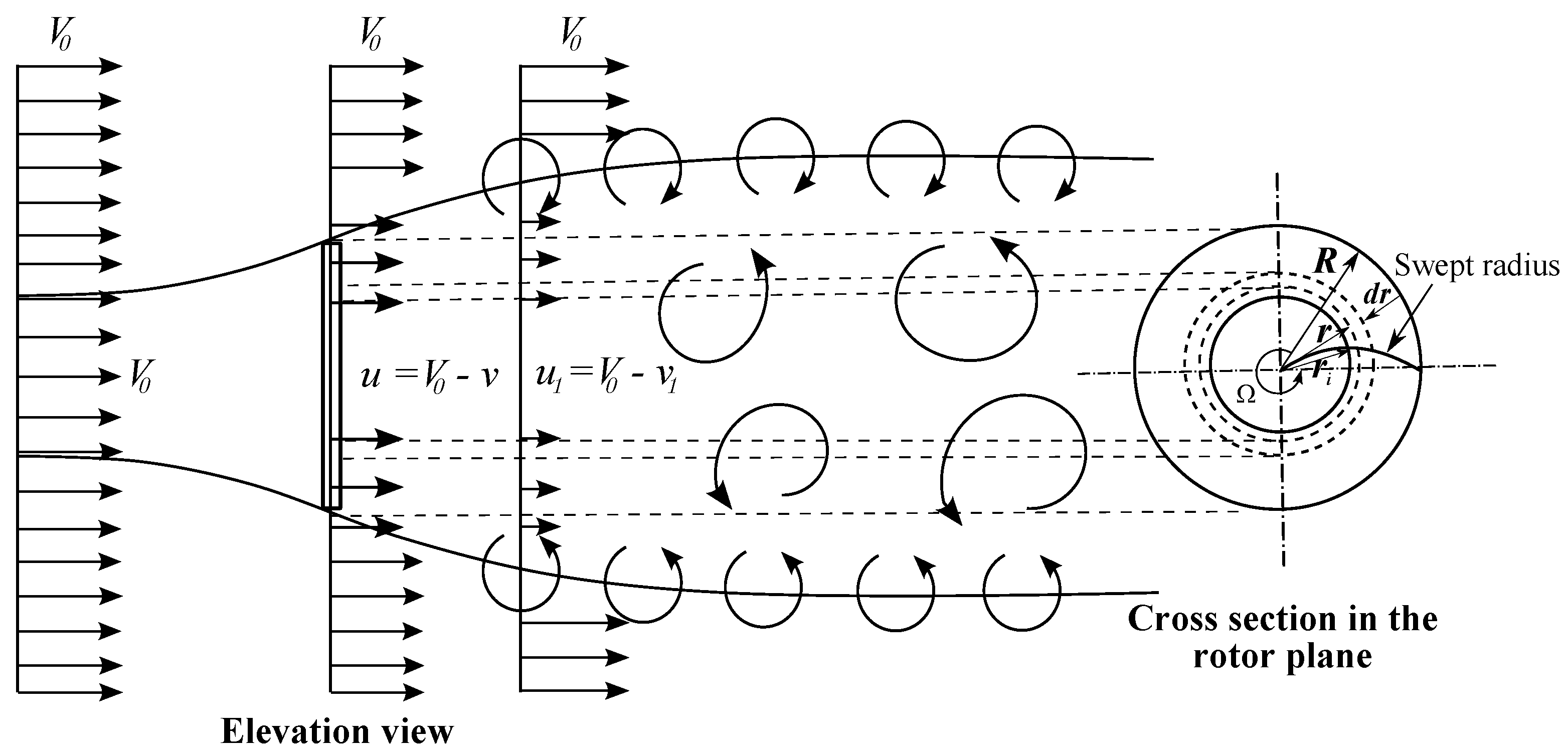
2.1. Axial Momentum Theory with Sweep Effect

The axial momentum theory with sweep effect, considering the rotational velocity component, is illustrated in Figure 1. In this case, the change is made only on the radial position r, which is transformed through the function,
Φ r R , β i = r R β i .
Thus, the swept radial position r i is taken as
r i = r R Φ r R , β i ,
where R is the radius of the turbine at the blade tip, while β i is the local swept angle. As it is well known from the literature, there is no rotation in the wake of a conventional actuator disk, but rotation is an essential part of power extraction, in that the elemental torque, d Q , is obtained directly from the angular momentum equation applied to an infinitesimal control volume of area d A = 2 π r i d r i (Figure 1) [20].
d Q = ρ V 1 w r i 2 d A = 2 ρ a ( 1 a ) V 0 Ω r i 2 d A ,
where r i is the swept radius, w = 2 Ω a is the angular velocity in the near-wake, and Ω is the rotor angular velocity, while a and a are the tangential and axial induction factors, respectively. The torque coefficient is [21]
C Q = d Q 1 2 ρ V 0 2 d A = 4 a ( 1 a ) Ω r i 2 V 0 .
The element power is obtained from [22]
d P = Ω d Q = 2 ρ a ( 1 a ) V 0 Ω 2 r i 2 d A .
By integrating this expression across the rotor, the power coefficient is given by [22]
C P = P 1 2 ρ A V 0 3 = 8 λ 2 0 λ a ( 1 a ) x 3 d x ,
where x = Ω r i / V 0 and λ = Ω R / V 0 are the local-speed ratio and the tip-speed ratio, respectively. The main change in Equation (6) is that C P is heavily dependent on the swept radial position r i from Equation (2).

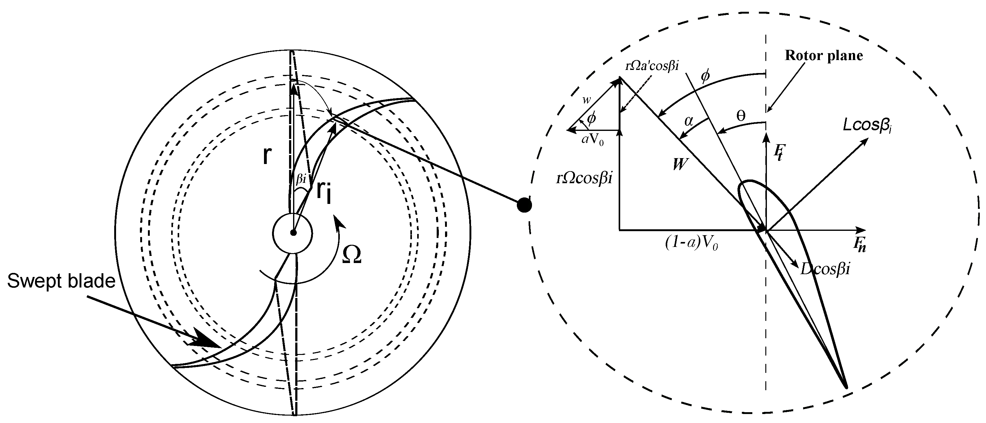
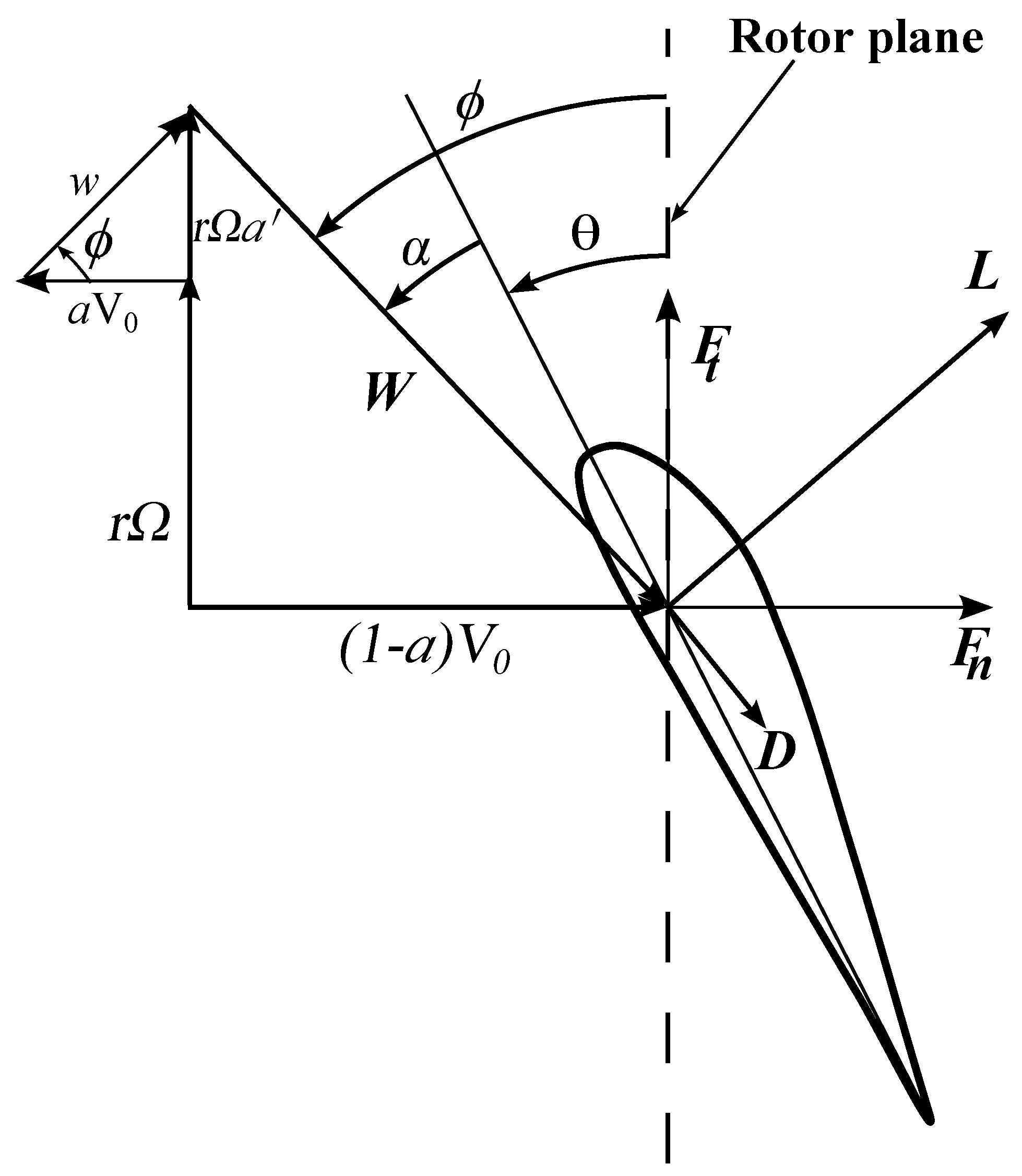
2.2. Blade Element Momentum Theory for Turbines with Swept Blades

To demonstrate the BEMT analysis to turbines with swept blades, Figure 2 depicts a rotor with N = 2 ; this number is used in the figure only for convenience, as the following analysis holds for any N. The transformations occur on the tangential velocity component, chord, lift and drag forces. The mathematical transformations for the radius and chord, respectively, are r i = r R Φ r R , β i and c i = c cos β i , where R is the radius at the blade tip, r and c are the local radius and chord for a straight blade, and β i is the local swept angle. The maximum swept angle at the blade tip is β , and β i = β / N r , where N r is the number of blade elements. The transformation function at each radial position Φ r R , β i is given by Equation (1). The following mathematical demonstrations are straightforward from the BEMT analysis, where the major additional term is cos β i as in Figure 2, in which the flow angle ϕ becomes
tan ϕ = 1 a V 0 1 + a Ω r i cos β i .
The relative velocity W and the bound circulation of each element, Γ , are
W = 1 a V 0 2 + 1 + a Ω r i cos β i 2
and [21]
Γ = 1 2 W c i C l 1 C d C l tan ϕ ,
where C l and C d are the lift and drag coefficients, respectively. The normal and tangential force coefficients C n and C t are [22]
C n = C l cos ϕ + C d sin ϕ cos β i
and
C t = C l sin ϕ C d cos ϕ cos β i
Extended formulations for axial and tangential flow velocities are given by
a 1 a = σ i C n 4 F sin 2 ϕ
and
a 1 + a = σ i C t cos β i 4 F sin ϕ cos ϕ
In order for Prandtl’s model to be adapted to the method of the blade element, Glauert gave a different solution. In this case, he interpreted that the correction factor, F P , can be approximated by the ratio between the induced velocity in the blades and the average of the induced velocity between the blades [23]
F P = a ¯ a B ,
where
a ¯ = 1 2 π 0 2 π a d θ
is the average induced speed and a B is the blade induced speed. Glauert wrote the factor F P in terms of the local flow angle, ϕ , leading to [23]
F P = 2 π cos 1 exp f ,
in which f, to the tip of the blade, assumes the expression
f = N 2 R r r sin ϕ .
Note that σ i = N c i / ( 2 π r i ) is the local solidity for the swept blade. Whether β i = 0 , or c i = c , r i = r , Equations (12) and (13) reduce to the classical Glauert expressions. The extended formulations for thrust and torque coefficients are
C T = 2 r h 1 W V 0 2 σ i C n r i d r i
and
C Q = 2 r h 1 W V 0 2 σ i C t r i 2 d r i ,
where r h is the radius of the hub normalized by R. The power coefficient is calculated through C P = λ C Q .

2.3. Optimization Model for the Turbine Swept Blade

The aerodynamic optimization is performed by maximizing the power coefficient through maximizing the integrand a ( 1 a ) in Equation (6). This requires [22]
d d a a ( 1 a ) = ( 1 a ) d a d a a = 0
So, Equation (20) can be simplified to an equation that also applies to turbines with straight blades as used by Rio Vaz et al. [1]:
( 1 a ) d a d a = a
According to Hansen [22], if the local angles of attack are below stall, a and a are not independent since the force according to potential flow theory is perpendicular to the local velocity seen by the blade. The total induced velocity, w, must be in the same direction as the force, as illustrated in Figure 3. On the other hand, when the local angle of attack is above stall, Equation (21) becomes invalid since the drag, which is ignored in the potential theory, becomes large. As noted by Wood [24], Equation (21) is only strictly true if the vortex pitch is independent of r. In particular, for λ < 1 , the behavior of the induced velocity field seems to be heavily dependent on the radius. Ref. [24] shows that the numerical optimization of turbines with straight blades gave a constant pitch only when λ was around one or greater. Therefore, it is important to note that the present optimization procedure is valid for λ > 1 approximately, for which
x i 2 a ( 1 + a ) = a ( 1 a ) ,
where x i = Ω r i cos β i V 0 . Equation (22) is derived from the angle ϕ in Figure 3 in terms of
tan ϕ = a Ω r i cos β i a V 0 .
Equations (7) and (22), differentiated with respect to a, yield
( 1 + 2 a ) d a d a x i 2 = 1 2 a .
If Equations (21) and (24) are combined with Equation (22), the optimal relationship between a and a becomes [22]
a = ( 1 3 a ) / ( 4 a 1 ) .
Equation (25) is obtained by Glauert, as described in [20] for turbines with straight blades. The optimal relationship between x i and a is calculated substituting Equation (25) in Equation (22), resulting in
16 a 3 24 a 2 + 9 3 x i 2 a + x i 2 1 = 0 .
Because Equation (26), the blade optimization procedure can be expressed as a function of the induction factors once the blade element lift and drag are available. So, the optimal chord and the twist angle at each blade section are calculated through the following expressions:
c = 8 π r i F sin ϕ cos ϕ B C n a 1 + a
and [22]
θ = ϕ α .
Equation (27) comes from Equation (12), while Equation (28) comes direct from the velocity diagram shown in Figure 3. In the high λ limit, Equation (26) requires a 1 / 3 , as expected, even for swept blades. According to Wood [24], as λ 0 , a 1 / 4 , whereas the correct limit is 1/2 for an ideal turbine. This concern seems to be the same for the case of the swept rotor; however further investigation is necessary. Note that the local speed ratio x i is dependent on the local swept angle β i , whose effect is shown in the next section.

3. Results and Discussion
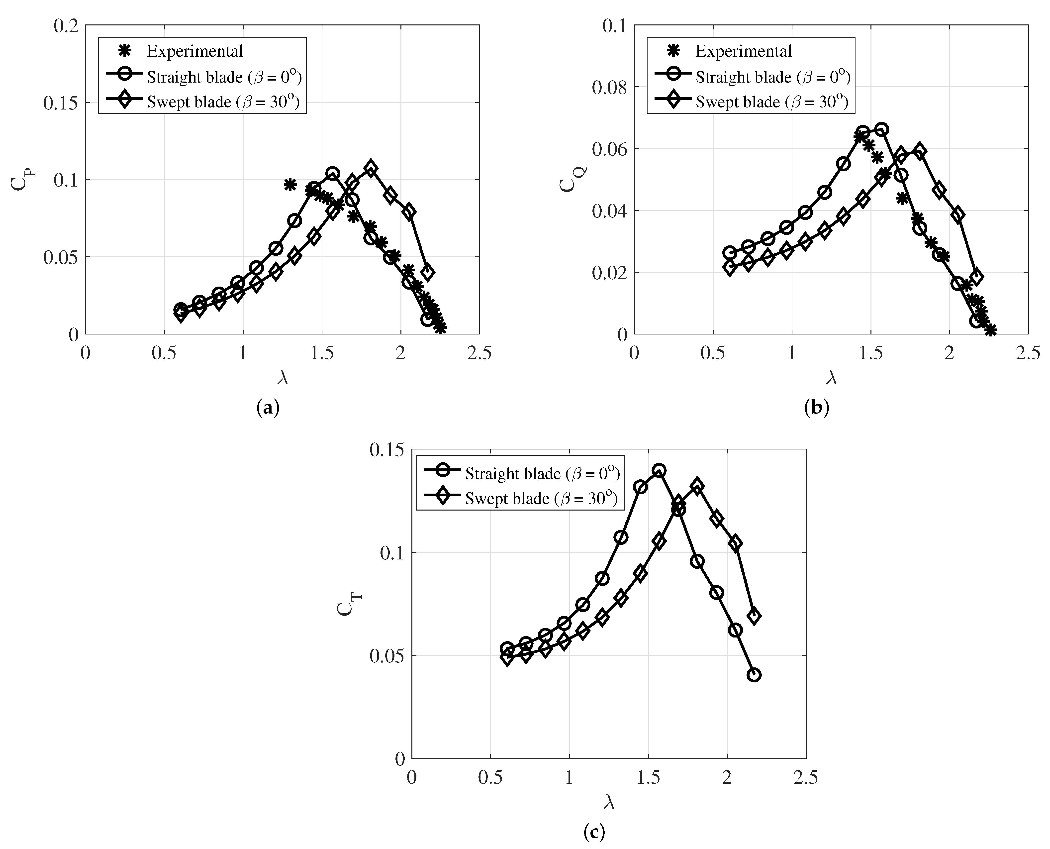
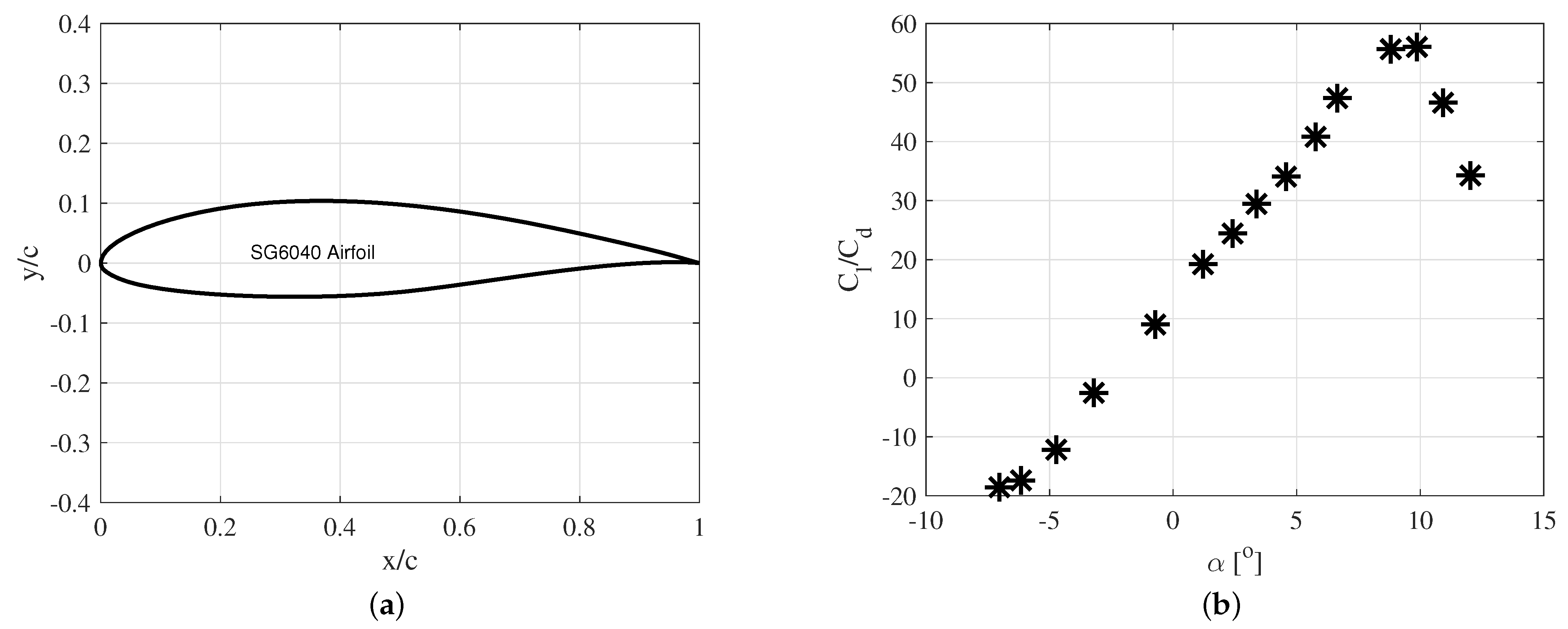
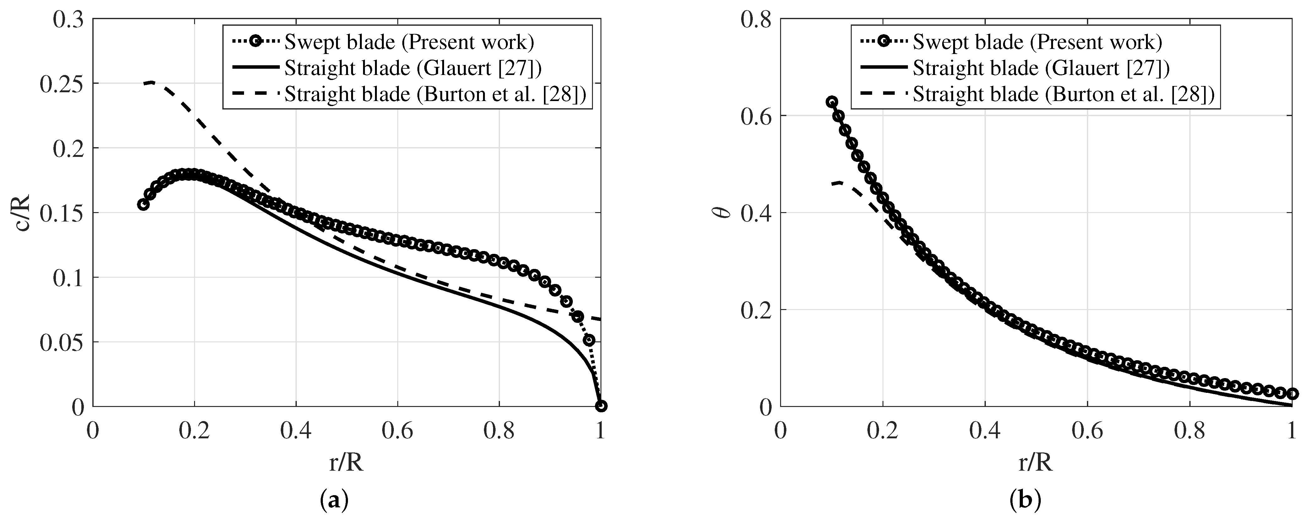
3.1. Validation

To validate the BEMT code developed in this work, a comparison with the experimental data measured by John et al. [25] was performed. The experimental data were made only for straight blades. In their work, it was used a typical curved plate airfoil for turbines with multiple blades, most used in water pumping, whose lift and drag coefficients were experimentally determined by Bruining [26] for Re = 60,000. The turbine tests were performed at the University of Calgary Red Wind Tunnel (RWT) and the TU Delft Open Jet Facility (OJF) [25]. Both tunnels are open jet. For the 15 m/s nominal wind speed investigated, the combined unsteadiness and turbulence intensity, and non-flow uniformity of the RWT were measured to be <0.3% and ±2%, respectively. The turbulent intensity of the OJF was reported to be <0.25%. These data were inserted into the proposed BEMT model, as described in Section 2 on the element moment theory with swept blades, in order to determine the turbine power, torque and thrust coefficients. The results, in Figure 4, demonstrate that power, torque and thrust coefficients increase for a tip speed ratio λ greater than 1.65 for the rotor with swept blades ( β = 30 ). For λ = 1.93 , the increase in power coefficient reaches 81% (Figure 4a). The same behavior occurs with the turbine torque, as shown in Figure 4b. In Figure 4c, for values of λ greater than 1.65, the thrust on the turbine with swept blades is greater than that of straight blades, demonstrating that the reduction in the axial aerodynamic load on the rotor occurs only in a range of λ , that is, for a certain turbine operating range. This result means that the thrust of turbines with swept blades is not always less than the thrust of turbines with straight blades. Additionally, it conflicts with that obtained by Zuo et al. [7], who point out that possibly the thrust in swept blades would always be lower than in straight blades.

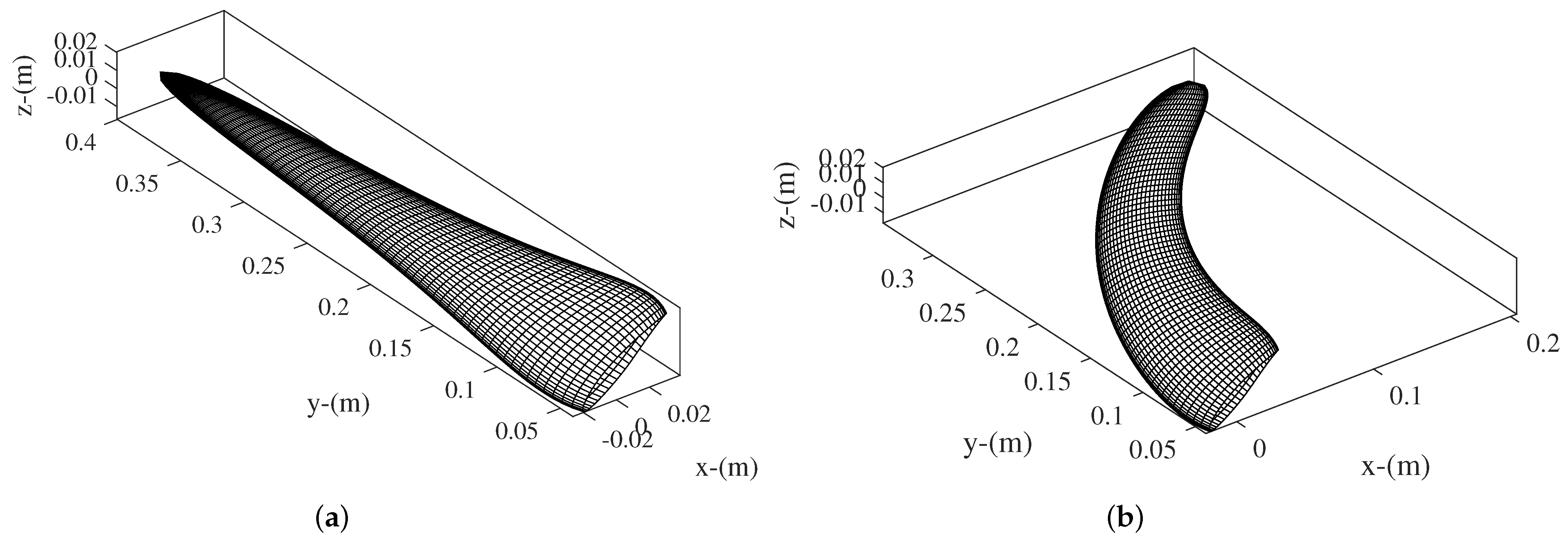
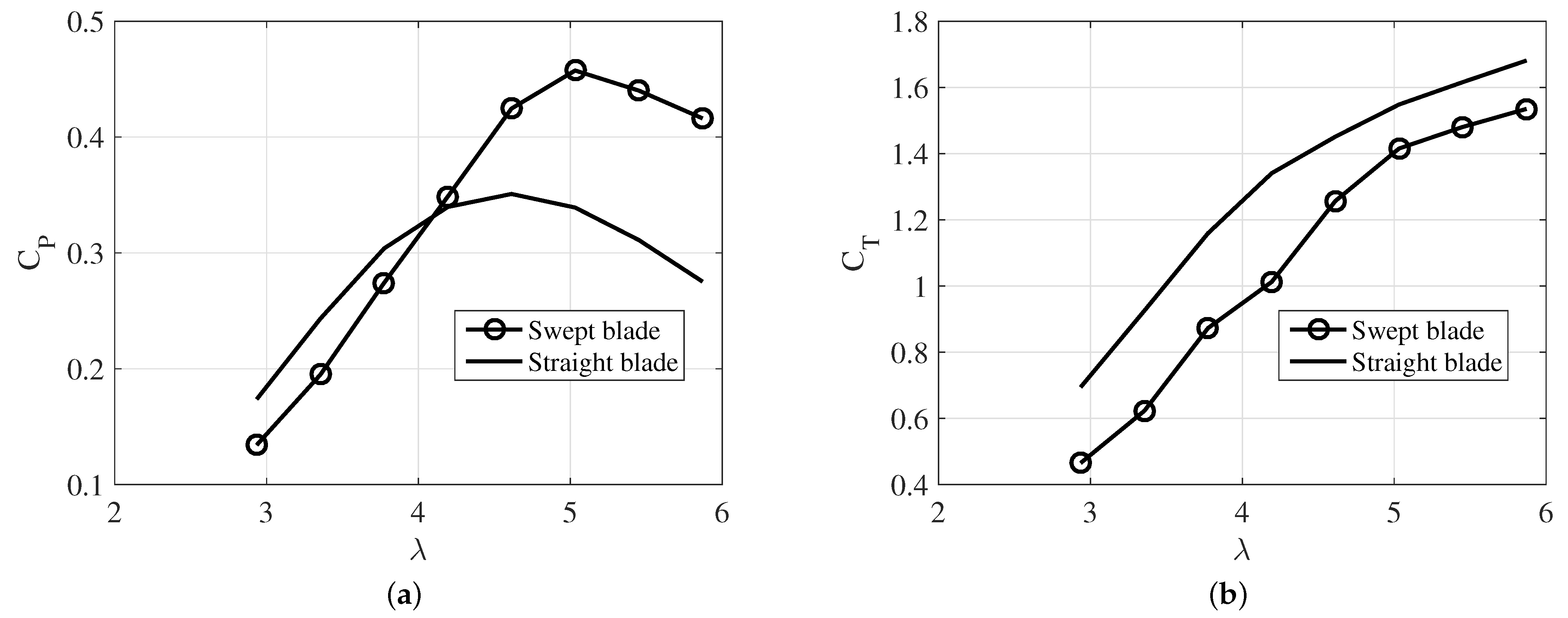
3.2. Performance Analysis of the Proposed Optimization

To analyze the performance of the proposed optimization model, the design parameters in Table 1 are taken into account. In this case, SG6040 airfoil is used (Figure 5), considering the low Reynolds number, given by R e = ρ V 0 c / μ . This airfoil, according to Wood [21] is one of the more modern SG aerofoils designed by Professor Michael Selig (S) and Phillipe Giguere (G) of the University of Illinios at Urbana-Champaign, specifically for small wind turbines. It is probably one of the first aerofoils designed for that purpose.
The optimal angle of attack ( α = 8 . 8 ) is obtained from the maximum C l / C d ratio, whose optimal value is 56, as shown in Figure 6. The optimization procedure is performed considering α constant, while the twist angle θ changes as a function of the flow angle ϕ along the blade length, from Equation (28). The SG6040 airfoil is used here just for the purpose of assessing the behavior of the proposed optimization since it is not the objective of the work to evaluate airfoils efficiencies, as well as the effect of 2D airfoil profiles.
Figure 6 shows the optimized chord (Figure 6a) and twist angle (Figure 6b) distributions along the turbine blade length. The results are compared to the optimization models developed by Glauert [27] and Burton et al. [28]. Note that, for the swept blade ( β = 30 ), the chord heavily increases, while the other optimizations applied to straight blades tend to be narrower. This result is interesting because a larger chord distribution can avoid cavitation in hydrokinetic turbines. This subject was also observed by Picanço et al. [29], who developed an approach for the optimization of diffuser-augmented hydrokinetic blades free of cavitation. In their work, to avoid cavitation, the chord distribution along the blade needs to increase as a reaction to the changing of the relative velocity approaching the rotor in order to keep the local pressure below the water vapor pressure. Here, cavitation is not evaluated, being that this is an assumption for future work. However, the result demonstrates that hydrokinetic turbines of swept blades deserve attention in terms of hydrodynamic aspects. At the blade root, the optimization developed in [28], the chord distribution is higher than the other models. This occurs because in [28], the chord increases when the relative velocity, given by Equation (8), decreases, as it is at the blade root. Figure 7 depicts the optimized shapes of the straight and swept blades. The turbine with swept blade keeps the same diameter as the straight blade. However, the blade length is increased about 4%, consequently increasing the rotor torque. Torque and power coefficients of the optimized rotors for λ = 4.19 are shown in Table 2, considering only the optimal values of Equations (4) and (6). The torque of the turbine with swept blades is about 18% higher than that with straight blades. Consequently, the power coefficient of the rotor with swept blades is also higher than for straight blades, reaching 52.9%.
Figure 8a shows the sweep effect on the behavior of Prandtl’s tip loss factor, F P , which goes to zero at the blade tip. Note that F P seems to be not sensitive to the sweep effect, as the curves for both, swept and straight blades are almost the same. On the other hand, in Figure 8b, the bound circulation, Γ , demonstrates a strong change for swept rotors. Clearly, the sweep effect increases the circulation at the middle and close to the tip of the blade. This increase in circulation increases the power extraction, but it also may increase the effect of cavitation. This is a very important phenomenon for hydrokinetic turbine blade optimization, which is intensified when operating at a tip speed ratio lower than 1. This result suggest that Prandtl’s tip loss factor seems to be not the best one for swept rotors. Possibly, methods based on finite blade functions, as stated in [30,31] are more appropriate, as they are dependent on the circulation, Γ . However, they are more complex in their implementation.
Figure 9a shows a comparison of the power coefficient for both swept and straight blades. For λ > 4.1 , the turbine with swept blade is more efficient. So, depending on the operating condition of the turbine, it can be better to use swept blades instead straight ones. Figure 9b depicts the result on the impact of the axial load (thrust coefficient C T ) on the rotor. The thrust is reduced for any λ . This is important because turbines with swept blades may reduce the resistive torque of the powertrain at any operating condition, contributing to a better performance of the rotor drivetrain.

4. Conclusions

This work presents a new optimization procedure applied to hydrokinetic turbines with swept blades. A comparison with an optimized hydrokinetic straight blade is performed, showing interesting results with good contributions to the current state of the art. The model has low computational cost and easy numerical implementation. The proposed methodology consists of an extension of the axial and blade element theories to the case of backward swept blades through a radial transformation function. Such a transformation heavily affects the chord and twist angle distributions along the blade, increasing the turbine torque and power coefficient. In the case of the torque, it can be increased by about 18%. Additionally, optimized swept blades seem to reduce cavitation on the hydrokinetic turbine, as the chord heavily increases at the blade tip. Another important result of the model is that the thrust of turbines with swept blades is not always less than the thrust of turbines with straight blades when using curved plate airfoils (Figure 4c). This seems to be due to the complex behavior of the boundary layer detachment on the airfoil at low Reynolds number. On the other hand, when the turbine uses SG6040 airfoil, the thrust is reduced for any operating condition, as shown in Figure 9b. For future works, a cavitation criterion based on the minimum pressure coefficient at each blade section will be implemented, in order to assess the cavitation effect in hydrokinetic swept blades. In addition, turbine performance in off-design conditions for different values of the tip speed ratio will be studied.

Author Contributions

Writing—review & editing, M.L.A.G., O.R.S. and J.R.P.V. All authors have read and agreed to the published version of the manuscript.

Funding

This research received no external funding.

Institutional Review Board Statement

Not applicable.

Informed Consent Statement

Not applicable.

Data Availability Statement

Not applicable.

Acknowledgments

The authors would like to thank the INEOF, CNPq, PROCAD/CAPES (Agreement: 88881.200549/2018-01), FAPESPA, and PROPESP/UFPA (PAPQ) for financial support.

Conflicts of Interest

The authors declare no conflict of interest.

Nomenclature

Latin Symbols
a, a Axial and tangential induction factors at the rotor
a o p t Optimal axial induction factor
BNumber of blades
cChord (m)
C D Drag coefficient
C L Lift coefficient
C M Torque coefficient
C n Normal force coefficient
C P Power coefficient
C P o p t Optimal power coefficient
C t Tangential force coefficient
C T Thrust coefficient
d A Elementary area (m2)
FPrandtl tip-loss factor
p 0 Pressure in the external flow (Pa)
p 2 Pressure at the turbine upstream (Pa)
p 3 Pressure at the diffuser outlet (Pa)
POutput power (W)
rRadial position at the rotor plane (m)
RRadius of the rotor (m)
V 0 Freestream wind velocity (m/s)
V 3 Axial velocity at the diffuser outlet (m/s)
wTotal induced velocity (m/s)
WRelative velocity (m/s)
xLocal speed ratio
Greek Symbols
α Angle of attack (rad)
β Twist angle (rad)
λ Tip speed ratio
ρ Density of the fluid (kg/m3)
σ Solidity of the turbine
ϕ Flow angle (rad)
Ω Angular speed of the turbine (rad/s)

References

  1. do Rio Vaz, D.A.; Vaz, J.R.; Silva, P.A. An approach for the optimization of diffuser-augmented hydrokinetic blades free of cavitation. Energy Sustain. Dev. 2018, 45, 142–149. [Google Scholar] [CrossRef]
  2. Betz, A. Introduction to the Theory of Flow Machines; Elsevier: Amsterdam, The Netherlands, 2014. [Google Scholar]
  3. da Silva, P.A.S.F.; Shinomiya, L.D.; de Oliveira, T.F.; Vaz, J.R.P.; Mesquita, A.L.A.; Junior, A.C.P.B. Design of hydrokinetic turbine blades considering cavitation. Energy Procedia 2015, 75, 277–282. [Google Scholar] [CrossRef] [Green Version]
  4. Muratoglu, A.; Tekin, R.; Ertuğrul, Ö.F. Hydrodynamic optimization of high-performance blade sections for stall regulated hydrokinetic turbines using Differential Evolution Algorithm. Ocean. Eng. 2021, 220, 108389. [Google Scholar] [CrossRef]
  5. Larwood, S.; Van Dam, C.P.; Schow, D. Design studies of swept wind turbine blades. Renew. Energy 2014, 71, 563–571. [Google Scholar] [CrossRef] [Green Version]
  6. Sessarego, M.; Ramos-García, N.; Shen, W.Z. Analysis of winglets and sweep on wind turbine blades using a lifting line vortex particle method in complex inflow conditions. In Journal of Physics: Conference Series; IOP Publishing: Bristol, UK, 2018; Volume 1037, p. 022021. [Google Scholar]
  7. Zuo, H.M.; Liu, C.; Yang, H.; Wang, F. Numerical Study on the Effect of Swept Blade on the Aerodynamic Performance of Wind Turbine at High Tip Speed Ratio. In Journal of Physics: Conference Series; IOP Publishing: Bristol, UK, 2016; Volume 753, p. 102010. [Google Scholar]
  8. Bora, B.J.; Dai Tran, T.; Shadangi, K.P.; Sharma, P.; Said, Z.; Kalita, P.; Nguyen, X.P. Improving combustion and emission characteristics of a biogas/biodiesel-powered dual-fuel diesel engine through trade-off analysis of operation parameters using response surface methodology. Sustain. Energy Technol. Assess. 2022, 53, 102455. [Google Scholar] [CrossRef]
  9. Zahedi, R.; Zahedi, A.; Ahmadi, A. Strategic study for renewable energy policy, optimizations and sustainability in Iran. Sustainability 2022, 14, 2418. [Google Scholar] [CrossRef]
  10. Rajamoorthy, R.; Arunachalam, G.; Kasinathan, P.; Devendiran, R.; Ahmadi, P.; Pandiyan, S.; Sharma, P. A novel intelligent transport system charging scheduling for electric vehicles using Grey Wolf Optimizer and Sail Fish Optimization algorithms. Energy Sources Part A Recover. Util. Environ. Eff. 2022, 44, 3555–3575. [Google Scholar] [CrossRef]
  11. Sadollah, A.; Nasir, M.; Geem, Z.W. Sustainability and optimization: From conceptual fundamentals to applications. Sustainability 2020, 12, 2027. [Google Scholar] [CrossRef] [Green Version]
  12. Ding, Y.; Zhang, X. An optimal design method of swept blades for HAWTs. J. Renew. Sustain. Energy 2016, 8, 043303. [Google Scholar] [CrossRef]
  13. Fei, C.W.; Li, H.; Lu, C.; Han, L.; Keshtegar, B.; Taylan, O. Vectorial surrogate modeling method for multi-objective reliability design. Appl. Math. Model. 2022, 109, 1–20. [Google Scholar] [CrossRef]
  14. Fei, C.; Wen, J.; Han, L.; Huang, B.; Yan, C. Optimizable Image Segmentation Method with Superpixels and Feature Migration for Aerospace Structures. Aerospace 2022, 9, 465. [Google Scholar] [CrossRef]
  15. Han, L.; Li, P.; Yu, S.; Chen, C.; Fei, C.; Lu, C. Creep/fatigue accelerated failure of Ni-based superalloy turbine blade: Microscopic characteristics and void migration mechanism. Int. J. Fatigue 2022, 154, 106558. [Google Scholar] [CrossRef]
  16. Pavese, C.; Kim, T.; Murcia, J.P. Design of a wind turbine swept blade through extensive load analysis. Renew. Energy 2017, 102, 21–34. [Google Scholar] [CrossRef] [Green Version]
  17. Kaya, M.N.; Kose, F.; Ingham, D.; Ma, L.; Pourkashanian, M. Aerodynamic performance of a horizontal axis wind turbine with forward and backward swept blades. J. Wind. Eng. Ind. Aerodyn. 2018, 176, 166–173. [Google Scholar] [CrossRef] [Green Version]
  18. Ning, A.; Hayman, G.; Damiani, R.; Jonkman, J.M. Development and validation of a new blade element momentum skewed-wake model within AeroDyn. In 33rd Wind Energy Symposium; American Institute of Aeronautics and Astronautics: Reston, VA, USA, 2015; p. 0215. [Google Scholar]
  19. Vaz, J.R.; Wood, D.H. Effect of the diffuser efficiency on wind turbine performance. Renew. Energy 2018, 126, 969–977. [Google Scholar] [CrossRef]
  20. Vaz, J.R.P.; Wood, D.H. Aerodynamic optimization of the blades of diffuser-augmented wind turbines. Energy Convers. Manag. 2016, 123, 35–45. [Google Scholar] [CrossRef]
  21. Wood, D. Small Wind Turbines: Analysis, Design, and Application; Springer: Berlin/Heidelberg, Germany, 2011. [Google Scholar]
  22. Hansen, M. Aerodynamics of Wind Turbines, 2nd ed.; Earthscan: London, UK, 2008. [Google Scholar]
  23. Clifton-Smith, M.J. Wind Turbine Blade Optimisation with Tip Loss Corrections. Wind. Eng. 2009, 33, 477496. [Google Scholar] [CrossRef]
  24. Wood, D.H. Maximum wind turbine performance at low tip speed ratio. J. Renew. Sustain. Energy 2015, 7, 053126. [Google Scholar] [CrossRef]
  25. John, I.H.; Vaz, J.R.; Wood, D. Aerodynamic performance and blockage investigation of a cambered multi-bladed windmill. In Journal of Physics: Conference Series; IOP Publishing: Bristol, UK, 2020; Volume 1618, p. 042003. [Google Scholar]
  26. Bruining, A. Aerodynamic Characteristics of a Curved Plate Airfoil Section at Reynolds Numbers 60,000 and 100,000 and Angles of Attack From-10 to+ 90 Degrees; Report LR-281; Delft University of Technology, Department of Aerospace Engineering: Delft, The Netherlands, 1979. [Google Scholar]
  27. Glauert, H. Aerodynamic Theory; Durand, W.F., Ed.; Division L. Airplanes Propellers: NewYork, NY, USA, 1963; Chapter XI; Volume 4, pp. 191–195. [Google Scholar]
  28. Jenkins, N.; Burton, T.L.; Bossanyi, E.; Sharpe, D.; Graham, M. Wind Energy Handbook; John Wiley & Sons: Hoboken, NJ, USA, 2021. [Google Scholar]
  29. Picanço, H.P.; Kleber Ferreira de Lima, A.; Dias do Rio Vaz, D.A.T.; Lins, E.F.; Pinheiro Vaz, J.R. Cavitation Inception on Hydrokinetic Turbine Blades Shrouded by Diffuser. Sustainability 2022, 14, 7067. [Google Scholar] [CrossRef]
  30. Vaz, J.R.; Okulov, V.L.; Wood, D.H. Finite blade functions and blade element optimization for diffuser-augmented wind turbines. Renew. Energy 2021, 165, 812–822. [Google Scholar] [CrossRef]
  31. Wood, D.H.; Okulov, V.L.; Vaz, J.R.P. Calculation of the induced velocities in lifting line analyses of propellers and turbines. Ocean. Eng. 2021, 235, 109337. [Google Scholar] [CrossRef]
Figure 1. Simplified illustration of the velocities at the rotor plane and in the wake for a swept radius [20].
Sustainability 14 13968 g001
Figure 2. Simplified illustration of the variable transformations on a swept blade.
Sustainability 14 13968 g002
Figure 3. Velocity diagram for the section of the rotor blade.
Sustainability 14 13968 g003
Figure 4. (a) Power, (b) torque, and (c) thrust coefficients.
Sustainability 14 13968 g004
Figure 5. (a) SG6040 airfoil for the section of the rotor blade. (b) C l / C d ratio for the SG6040 foil (Reynolds number of 150,000).
Sustainability 14 13968 g005
Figure 6. (a) Chord and (b) twist angle distributions as functions of the radial position.
Sustainability 14 13968 g006
Figure 7. Optimized shapes of (a) straight and (b) swept blades.
Sustainability 14 13968 g007
Figure 8. (a) Prandtl’s tip loss, F P , and (b) bound circulation, Γ .
Sustainability 14 13968 g008
Figure 9. (a) Potência e (b) thrust coeficients as functions of the tip-speed ratio λ .
Sustainability 14 13968 g009
Table 1. Design parameters and conditions of the turbine.
ParametersValue
Turbine diameter, m0.8
Hub diameter, m0.08
Number of blades4
Stream velocity, m/s1.0
water density, kg/m3 (1)997
Angular velocity, rad/s10.5
Swept angle, degrees30
(1) at 25 °C.
Table 2. Torque and power coefficients of the turbines.
Swept BladesStraight Blades
C Q 0.130.11
C P 0.5290.46
Publisher’s Note: MDPI stays neutral with regard to jurisdictional claims in published maps and institutional affiliations.

