Article

Image-Analysis-Based Approach for Identification of Air Cooler Heat Transfer Degradation during Frosting Process

Thermal Engineering Department, Faculty of Mechanical Engineering, Bialystok Technical University, Wiejska 45C, 15-351 Bialystok, Poland
*
Author to whom correspondence should be addressed.
Sustainability 2022, 14(21), 13731; https://doi.org/10.3390/su142113731
Submission received: 9 September 2022 / Revised: 14 October 2022 / Accepted: 17 October 2022 / Published: 23 October 2022

Abstract

:
Fin-and-tube heat exchangers have been extensively used in many fields, especially in heat, ventilation, air-conditioning, and refrigeration systems. In the case of the operation of a fin-and-tube heat exchanger as an air cooler, frost formation is an important effect that should be taken into account. The frost accumulation process is undesirable since it deteriorates heat transfer due to the insulation of the frost layer as well as causing excessive pressure loss. The analysis of the effect of the frosting process on a fin-and-tube air cooler performance is presented in this paper. Based on long-term experimental investigations applied to the air cooler in a cold storage chamber, the general degradation of the heat exchanger performance is discussed. The influence of frost on the cooling capacity, by-pass factor, and thermal resistance is analysed. The temperature distribution of the air passing through the air cooler before and after the defrosting process is presented and discussed. A method for the assessment of the amount of frost formed at the air cooler surface, based on visualisation of the air cooler during operation and synchronised with the thermal measurements, is developed. The results show that the frosting process causes deterioration of the cooling capacity by up to 40% in the analysed case. Correlation is demonstrated between frost formation and heat transfer degradation in the air cooler.

1. Introduction

The frosting process occurs in many types of heat exchangers as an undesirable phenomenon since the layer of frost acts as an additional thermal resistance layer, which decreases the efficiency of heat transfer. Frost formation is a very complex process, so its recognition as well as its assessment of heat transfer degradation caused by frosting may be thought of as a problem still open to research [1]. Hayashi et al. [2] provided basic classification of the frosting process mechanism and divided the process into three periods: (i) crystal growth period, (ii) frost layer growth period, and (iii) full growth period. In the first period, a thin layer of frost covers the surface and accretion of thin crystals occurs; in the second period, density and thickness of the frost layer increase due to the generation and new formation of thin crystals at the upper layer, and the diffusion of water vapour inside the porous frost layer; in the third period, alternate melting and freezing of water occurs repeatedly when the surface of the layer reaches 0°C and ends when the equilibrium is achieved. The freezing of melted ice, located deeper in the frost layer, rapidly increases the frost density and decreases the thermal resistance in this period.
Numerous theoretical models of the frosting process for simple geometries of the air cooler have been developed. Sami and Duong [3] developed a model that predicts the frost density and thickness on flat surfaces and showed that frost formation is accelerated by a decrease in surface temperature and an increase in relative air humidity. Lee and Ro [4] presented simple models for frost growth on a flat plate, which takes into account the frost surface in undersaturated and supersaturated conditions. In these models, the initial porosities of the frost are important for the accurate determination of growth characteristics of the frost layer. In paper [5], a semi-empirical correlation for the thermal conductivity of frost, valid for porosity, ranging from 0.50 to 0.95, and wall surface temperatures from −30 °C to −4 °C, was presented. The equations were compared with correlations developed earlier and showed better accuracy. Wang et al. [6] presented a generalised simple model for frost growth on a flat plate. A modified correlation for initial frost density, based on the correlation proposed by Hayashi et al. [2], and equations for frost surface temperature, heat flux density, frost thickness, and density were proposed. Generalised correlations for frost properties were also developed and presented by Kandula [7]. Nascimento et al. [8] investigated frost growth and densification on parallel plate channels and proposed a semi-empirical correlation for frost density. Tahavvor and Yaghoubi [9] employed artificial neural networks to predict thickness and density of frost in a horizontal cylinder under natural convection. This geometry, along with the parallel plate channels, is widely used in heat exchangers for refrigeration. Four methods for the prediction of frost densification and growth on vertical, horizontal, and parallel flat plates were compared by Leoni et al. [10]. It was found that wall surfaces significantly impact the frosting process, and an increasing air velocity accelerates frost formation for all three geometries. These authors concluded that additional tests are required for all types of air cooler geometries. The frosting process for the fin-and-tube air coolers was also investigated by many researchers. Getu and Bansal [11] developed new frost property correlations that predict frost layer thickness, density, thermal conductivity, and air-pressure drops. Amini et al. [12] studied the frosting of fin-and-tube heat exchangers under natural convection for refrigerant mean temperatures of −20 °C, −15 °C, and −10 °C; ambient temperatures ranging from 20 °C to 30 °C; and air humidity from 50% to 70%. The authors observed that the air flow between compact fins is negligible as frost only formed on the tips of the fins, whilst the tubes and fins remained clean. Seker et al. [13] conducted a numerical analysis of the unsteady thermal characteristics of heat exchangers under forced convection and frosting conditions. The results of experimental investigations of the performance of fin-and-tube heat exchangers with flat fins are presented by Yan et al. [14]. The authors concluded that decreasing the air flow rate and increasing relative air humidity enhances frost formation. Fin pitch has little effect on the examined heat exchanger performance if the fin spacing is appropriately large. Liu et al. [15] experimentally examined the performance of perforated fin-and-tube heat exchangers under frosting conditions. It was concluded that while frost mass accumulated on perforated fins was higher than on plain fins, the heat transfer coefficient was higher for perforated fins by over 30%. A semi-empirical model for the prediction of non-uniform frost growth on a fin-and-tube heat exchanger that takes air redistribution into account was proposed by Padhmanabhan et al. [16]. These authors observed that the capacity of the heat exchanger and frost thickness were calculated with large errors (20–50%) if air flow redistribution was omitted. Lee et al. [17] investigated the influence of the fin pitch, inlet air and refrigerant temperatures, air flow rate, and relative humidity on frost growth on a spirally coiled fin-and-tube heat exchanger and found that humidity had a dominant effect on frost growth. A new CFD frosting model that has the effect of surface structure on frost development and describes the initial and growth periods of frosting was developed by Cui et al. [18]. The frost formation at the find-and-tube air cooler surface was also studied theoretically by Keryakos et al. [19].
Wang et al. [20] investigated frosting and defrosting on fin-and-tube exchangers with different surface characteristics: bare, hydrophilic, and superhydrophobic coatings. The frost mass and thickness on a superhydrophobic surface were 28.8% and 17.1% lower than on a bare heat exchanger. Hydrophobic coating significantly decreased both energy consumption for defrosting and ice melting time. Drainage of molten water was also accelerated. Pu et al. [21] carried out tests to determine the influence of coatings on the frosting/defrosting cycle in microchannel heat exchangers. It was shown that the hydrophobic coating significantly inhibited frost formation, but this effect was weaker after four frosting/defrosting cycles. The influence of a hydrophobic nano-coating on the frosting of a fin-and-tube heat pump evaporator was experimentally evaluated by Reichl et al. [22]. The authors concluded that coating significantly extended the time period between defrosting and reduced the frost mass growth rate by 16–25% for air temperatures ranging between −2.0 °C and +5.5 °C. Frost layer thickness was extracted based on captured images of the investigated evaporators. The influence of frost morphology on fan-supplied evaporators was investigated by da Silva et al. [23].
The issues of the identification of the thermal degradation of the air cooler due to the frosting process can still be thought of as an open issue. This paper presents an approach for the identification of the amount of frost formed at the air cooler surface by means of visualisation. The proposed method is validated using measurements taken during tests of the air cooler placed in a cold room used to store vegetables. Obviously, due to the complexity of the frosting process and heat transfer degradation, the assessed relationship between frost formation at the air cooler surface and heat transfer degradation is strongly non-linear. Therefore, the main objective of the presented research is the demonstration of the correlation between frost formation and heat transfer degradation on the basis of the long-term operation of the air cooler in the refrigerated vegetable storage chamber, i.e., under actual operation conditions.

2. Test Apparatus and Procedure

The tested air cooler was operated in a vegetable cold-store chamber. The tested air cooler was of a nominal cooling capacity of 1.148 kW and was operated in an indirect cooling system with a glycol solution as the heat transfer fluid. Air flow was forced by three silent fans with a diameter of 200 mm, a power consumption of 10 W each, and a nominal air flow rate of 1105 m3/h. The tested air cooler consisted of 18 tubes made of copper arranged in 9 circuits with 149 aluminium fins on the tubes. The fin dimensions were 202 × 90 × 0.25 mm with a fin pitch of 7.0 mm. The air cooler was equipped with two electric heaters for the defrosting process. The heat transfer area of the tested air cooler was 5.7 m2. The pressure drop for the nominal operation conditions was estimated as 6 Pa. A photograph of the tested air cooler is shown in Figure 1.
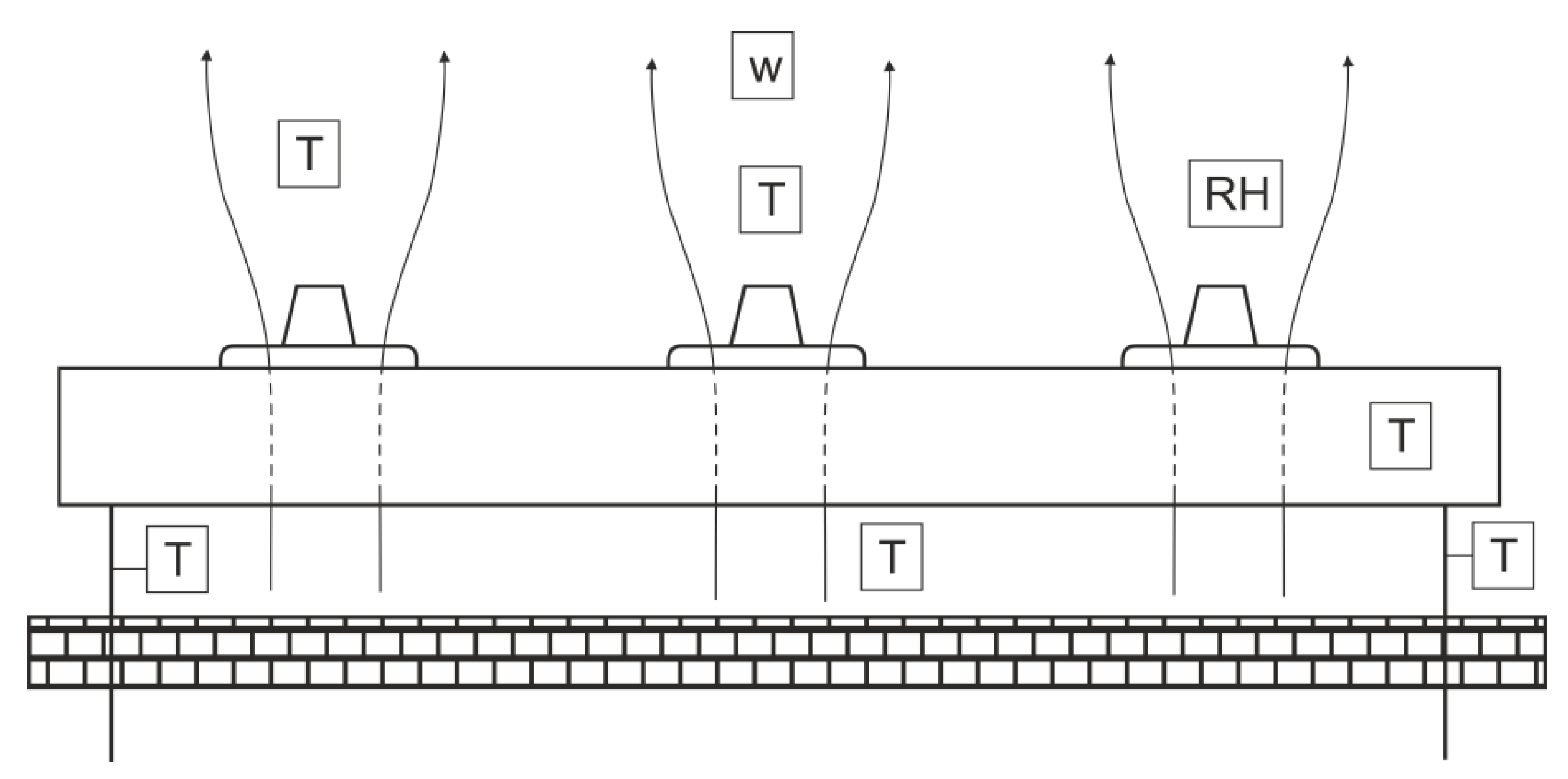
The locations of the sensors are shown in Figure 2. Photographs of the two sensors are given in Figure 3. The following measurements were made during the tests:
  • Relative humidity (RH), velocity (w), and temperature (T) of the outlet air;
  • Temperature (T) of the inlet air, see Figure 3a;
  • Inlet and outlet temperature (T) of glycol;
  • Temperature of the fins (see Figure 3b).
Air velocity was measured using a Delta Ohm HD103t omnidirectional probe with a measurement range of 0–5 m/s, accuracy of ±0.04 m/s for 0–1.0 m/s, and ±0.2 m/s for 1–5 m/s range. Relative humidity and temperature were measured by E+E Elektronik type J sensors with constant heating (measurement range 0–100% RH with accuracy of 1.5% for RH < 90% and 2.7% for RH > 90%) and thermocouples CZAKI 361K-3-W3.
The defrosting process, which lasted 10 min, was carried out two times a day. The frosting process is clearly visible in the photographs in Figure 4.

3. Approach for Frosting Process Identification

The proposed approach for the identification of the process of frosting is based on visualisation of the air cooler under actual operation conditions, i.e., in the cold storage room. The procedure of the visual identification of the frosting process requires preparation of photographs by dividing video files into images and cropping and converting those images into 8-bit grayscale images. The amount of frost was determined by counting pixels representing frost in the pictures, using an original algorithm developed in NI Vision Builder 2013, part of the NI LabView environment. Its operation is presented below In a synthetic way.
In the first step, video files containing photographs of the tested cooler were converted into grayscale images. Next, the range of shades (on an 8-bit grayscale where 0 represents black and 255 represents white) representing frost was assumed after analysing large numbers of air cooler photographs and carrying out a significant number of tests. Analysing several dozen hours of recordings, where pictures were taken every second, allowed us to credibly verify the correctness of operation of the proposed algorithm.
The inspection algorithm, prepared in Vision Builder, consists of three steps: acquisition of pictures, counting pixels, and saving the results to a text file. The second step (Count Pixels) was the calculation of the number of pixels in shades from a previously chosen range. This option works only with grayscale images; therefore, pictures had to be converted from RGB colour models, which were taken by the camera.
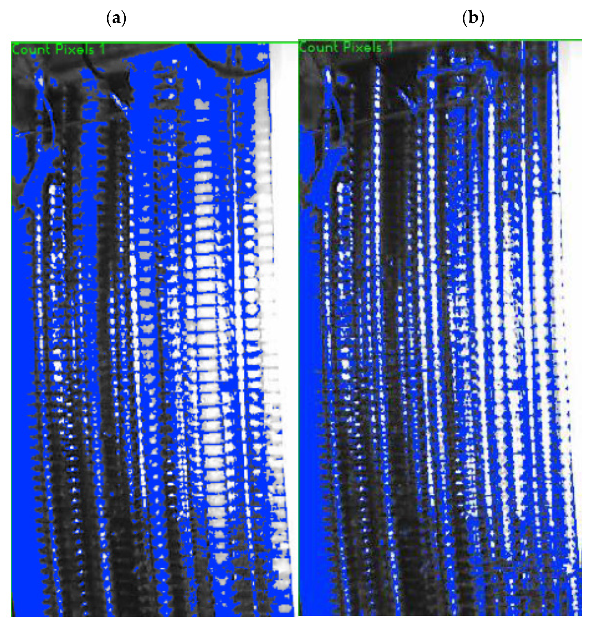
The scope of shades included by the Count Pixels tool can be set manually or by several automatic routines. In this analysis, the authors used the Gray Objects option with manually adjusted thresholds of colours. The right selection of the range of shades is a key issue. It was chosen after a careful observation of the air cooler photographs under different frosting conditions. Ultimately, a span of the 90th to 170th shade was selected. The blue area visible in Figure 5 represents all the pixels that fall into this range. The difference between a frosted and a clean cooler is clearly visible, which is the basis of the conducted analysis. In the frosted cooler (Figure 5a), the area indicated in blue is larger than that after defrosting (Figure 5b). The larger the blue area, the more frost that is present on the surface. Some areas of the cooler housing are also marked in blue, as it is depicted by shades falling into the range selected as shades that represent frost. Since the camera was not moved during recording, this area is constant and does not affect the changes in the number of pixels depicting frost. The proposed method requires that the photographs are of a high quality; that they are synchronised with saved measurements; and that the correct choice of shades of gray ranges, corresponding to the frost, is used. The proposed method also requires insightful observations and an analysis of a significant number of pictures.
The cooling capacity of the tested air cooler, bypass factor, and the change in thermal resistance after frosting were calculated according to the following formulas, respectively:
Q ˙ c = V ˙ g ρ g c g ( t g , o u t t g , i n )
B F = t 2 t s t 1 t s
Δ R fr = 1 k k f r
The bypass factor defined by Equation (2) indicates part of the total air through the coil, which fails to come into direct contact with the surface of the cooling coil. As an effect of this, the temperature of this part of the air does not drop, as this part of the air has direct contact with the cooling surface (i.e., heat transfer surface).
The reduction in the cooling capacity was calculated as
Δ Q ˙ c = Q ˙ c Q ˙ c , fr Q ˙ c
where Q ˙ c is the cooling capacity of the clean heat exchanger and Q ˙ c is the frosted heat exchanger
The heat transfer coefficient was calculated as
k = Q ˙ c A c Δ T m
where Ac is the heat transfer area, and Δ T m is the logarithmic mean temperature difference:
Δ T m = ( t in , fr t out , g , fr ) + ( t out , fr t in , g , fr ) ln ( t in , fr t out , g , fr t out , fr t in , g , fr )

4. Results

The tested air cooler, was operated in a cold storage chamber for vegetables during the long-term storage of napa cabbages [24,25]. Four measurement series were analysed (diagrams for one selected exemplary measurement series are presented in this paper). In addition to the comparison of selected measurements with the frosting level, the cooling capacity, thermal resistance of frost, and bypass factor were calculated. The frosting level and air and glycol temperatures are presented in Figure 6, Figure 7 and Figure 8, respectively. The data collected during defrosting were removed from the plots, as most of the parameters, especially the air and glycol temperatures, reached high values and reduced the readability of the diagrams.
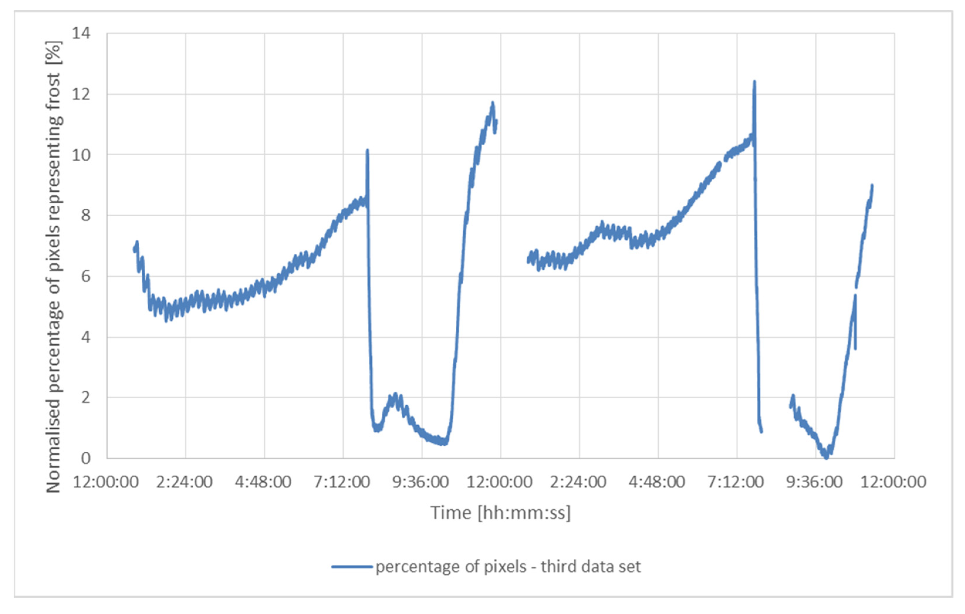
The air cooler was defrosted every 12 h. Its surface did not frost evenly between defrosting cycles, which is visible in Figure 6. The percentage of the pixels representing frost in the pictures varied from about 32% to about 50%. For each measurement series, the lowest percentage was subtracted from the percentage calculated for each photograph in a given series. This minimum was accepted as the moment when the air cooler surface was completely clean.
The percentages returned by the NI Vision Builder only indicates the number of pixels that fall into the chosen span of the 90th to 170th shade of grey in the whole photograph. It is an indirect measure proportional to the amount of ice formed at the air cooler surface. Zero percent in the photograph (Figure 6) describes the moment when the air cooler surface is clean. Additionally, 100% does not mean that the cooler is completely frozen due to the presence of other elements in the picture, e.g., the air cooler housing. These components were taken into consideration and did not affect the results.
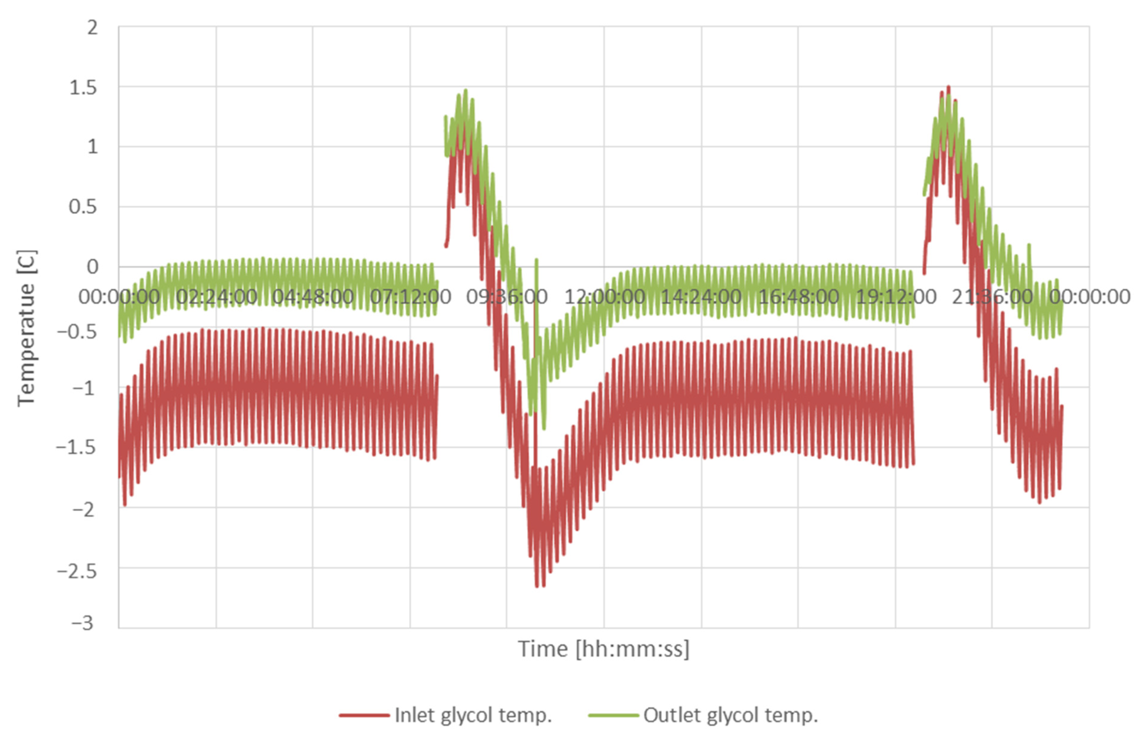
In the first half of the series, the frosting process was similar to other series; see Figure 6. The beginning of the plot depicts the stage after the second defrosting of the previous day. The air cooler was gradually covered in frost up to the first defrosting cycle at 8:00 am. After the frost was removed, a quick frosting process was started, and an almost steady increase in the amount of frost build-up until the second defrosting process occurred. The air temperature (Figure 7) before defrosting the air cooler increased slightly with frosting. The temperature behind the cooler behaved inversely. These changes were small, on the order of a tenth of a degree. Temperatures of glycol (Figure 8) decreased slightly with the frosting of the exchanger.
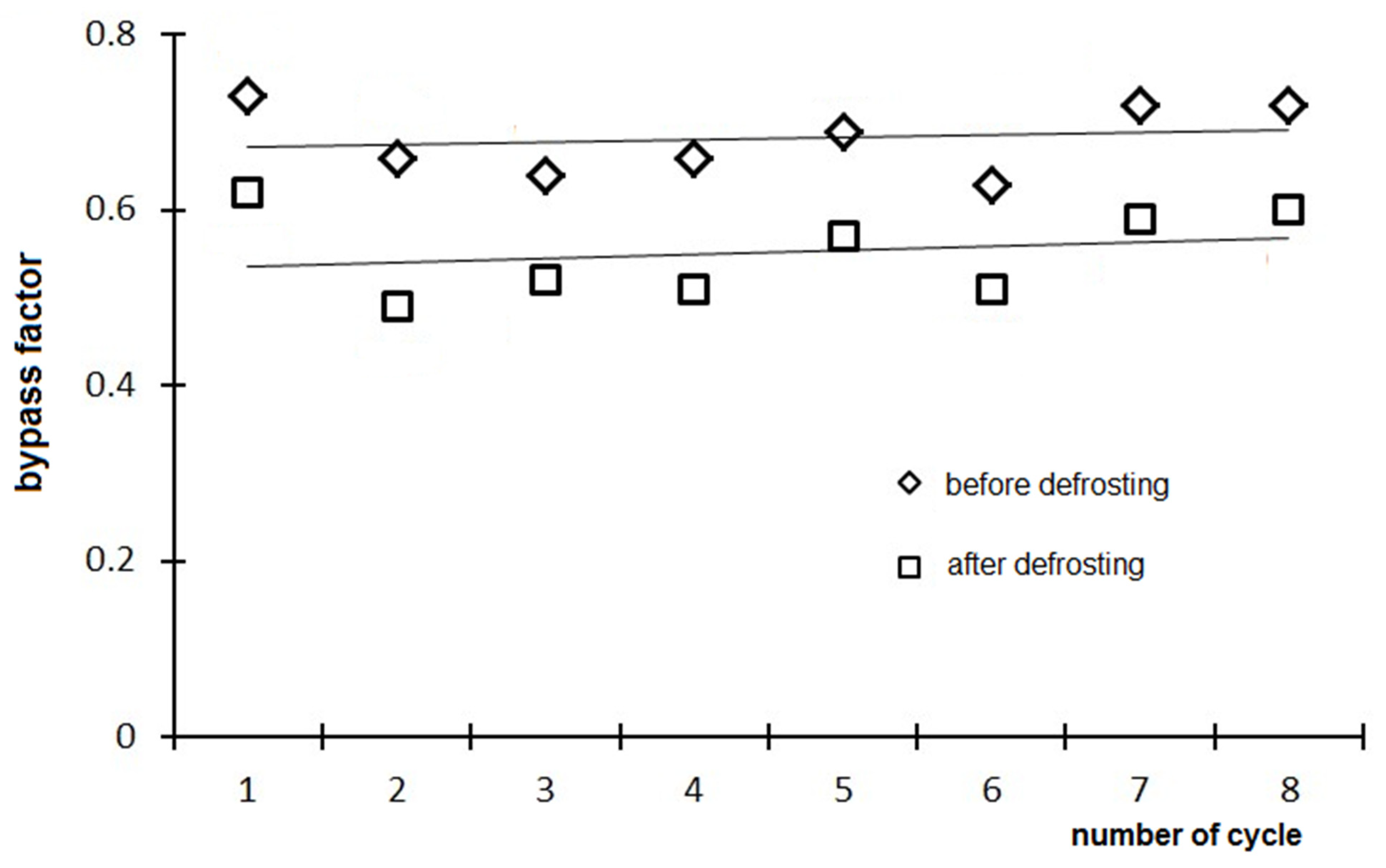
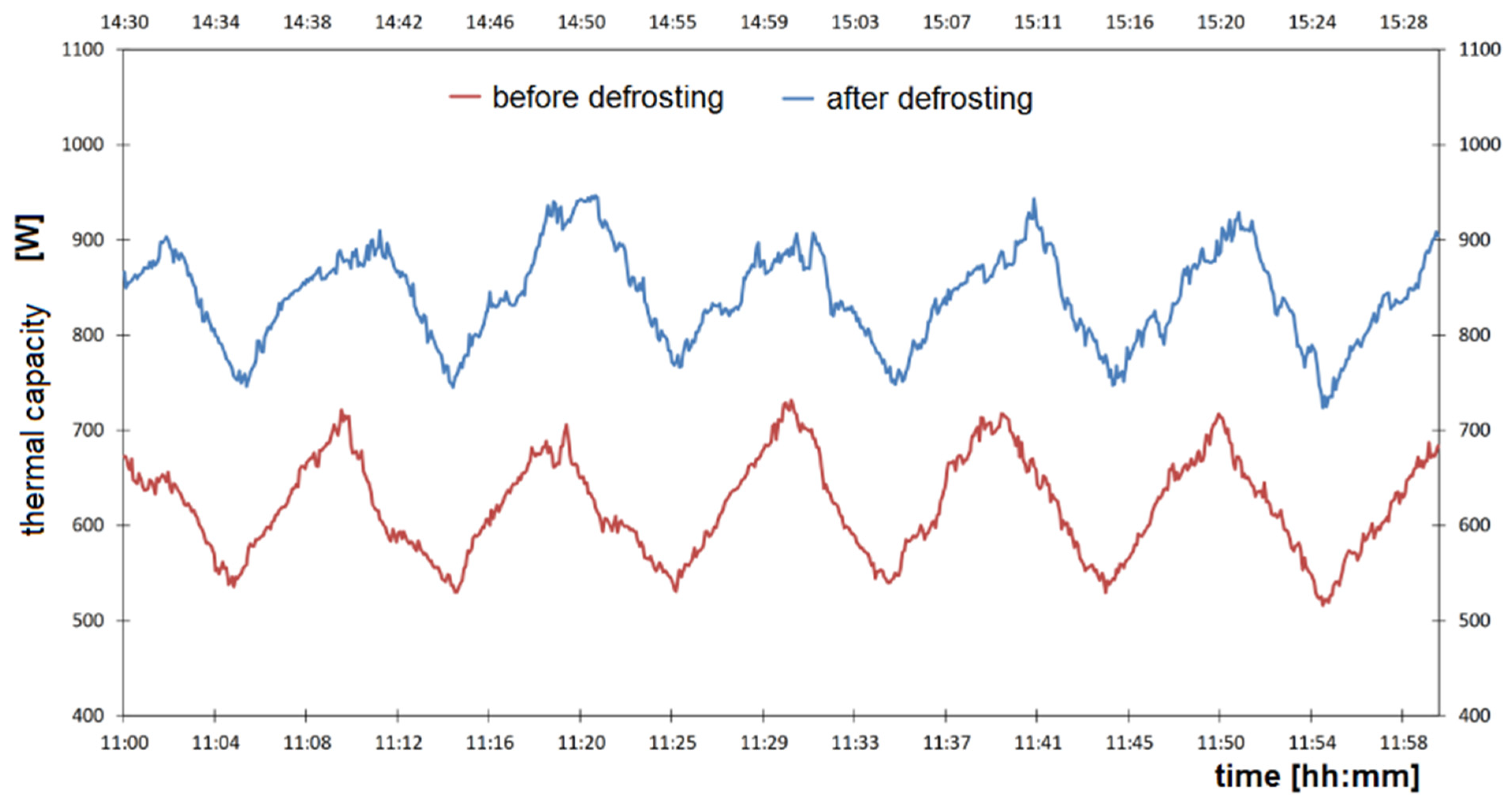
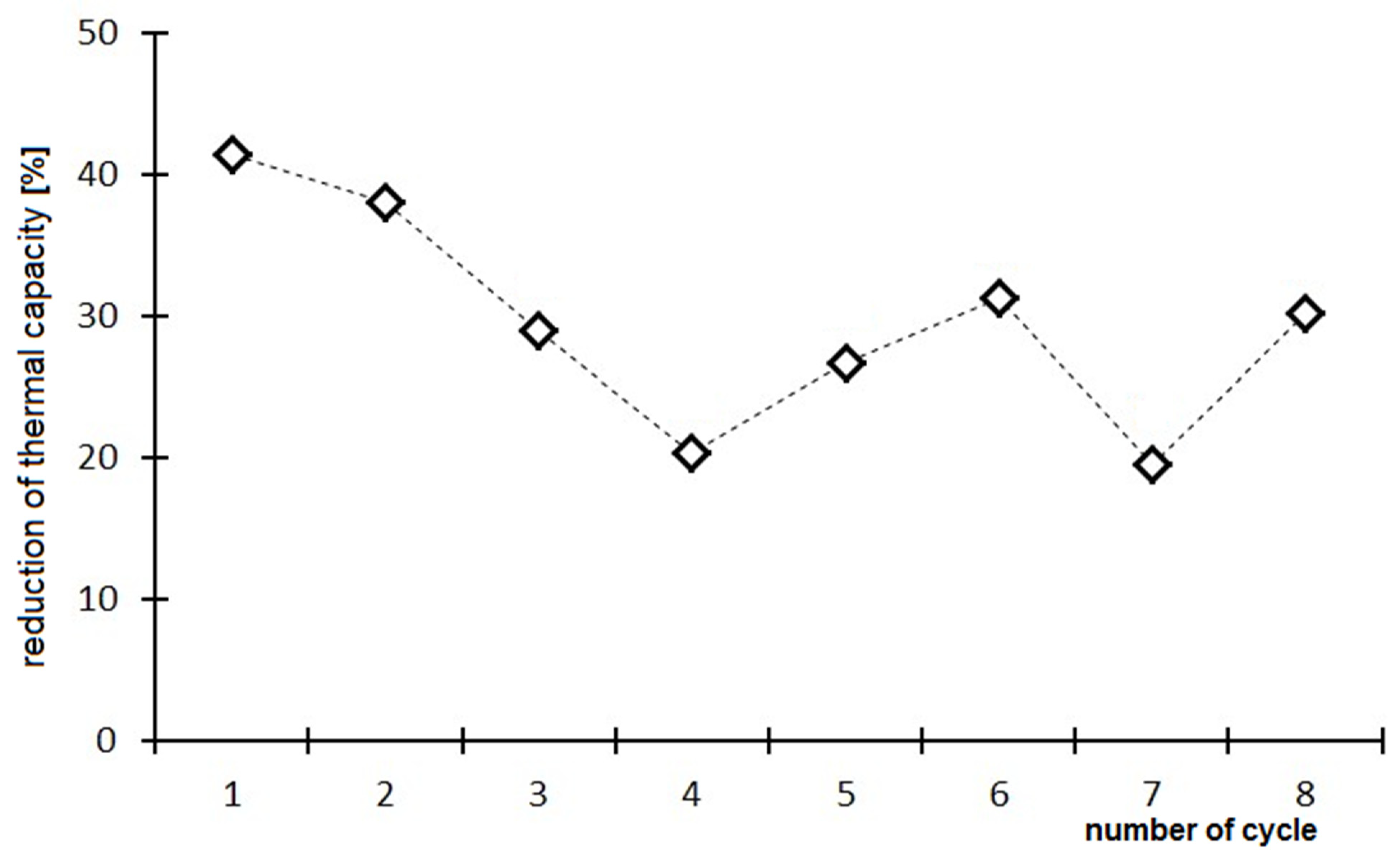
The results indicate that the frosting process decreased the air cooler capacity by 20–40% by increasing its bypass factor (BF) by about 18–35%; see Figure 9. The cooling capacity of the tested air cooler before and after defrosting varied from 0.75 kW to 0.9 kW; see Figure 10. The lowest calculated cooling capacity was about 0.35 kW, and the highest was about 1.2 kW. The reduction in the cooling capacity due to frosting for a longer period (eight cycles) is shown in Figure 11.
The bypass factor (Figure 9, Equation (2)) was very high and varied from 0.5 (clean heat exchanger surface) up to 0.7 (frosted up surface). The average bypass factor of the frosted cooler was 0.68 and 0.55 after defrosting. Due to the additional thermal insulation created by the frost layer on the fins, which deteriorates heat transfer between glycol and air, the temperature of the fins was higher than for the clean fins surface; see Figure 12. According to Table 1, the heat transfer coefficient varied in the range of 11–21 W/(m2⋅K) for the frosted surface and in the range of 15–31 W/(m2⋅K) for the clean surface. Maximum rise in the thermal resistance was 0.32 (m2⋅K)/W.
Figure 13 shows the average frosting level for four analysed days as a function of time, before the inflection point (Figure 13a) and after the inflection point (Figure 13b). This point indicates the maximum pixel percentage (see Figure 6) that occurred in the middle of every series, so the frosting cycle was repeatable. Approximation equations for both curves were determined as follows:
S b = 3283.6 τ 2 + 3231.4 τ 780.93
S a = 11686 τ 4 31308 τ 3 + 31197 τ 2 13715 τ + 2257.8
Equations (7) and (8) allow for the prediction of the frosting level. This proposed relationships can be used to further optimise the defrosting system operation. Dividing the curve into two parts was necessary due to the lack of accuracy of approximation for the whole averaged period.
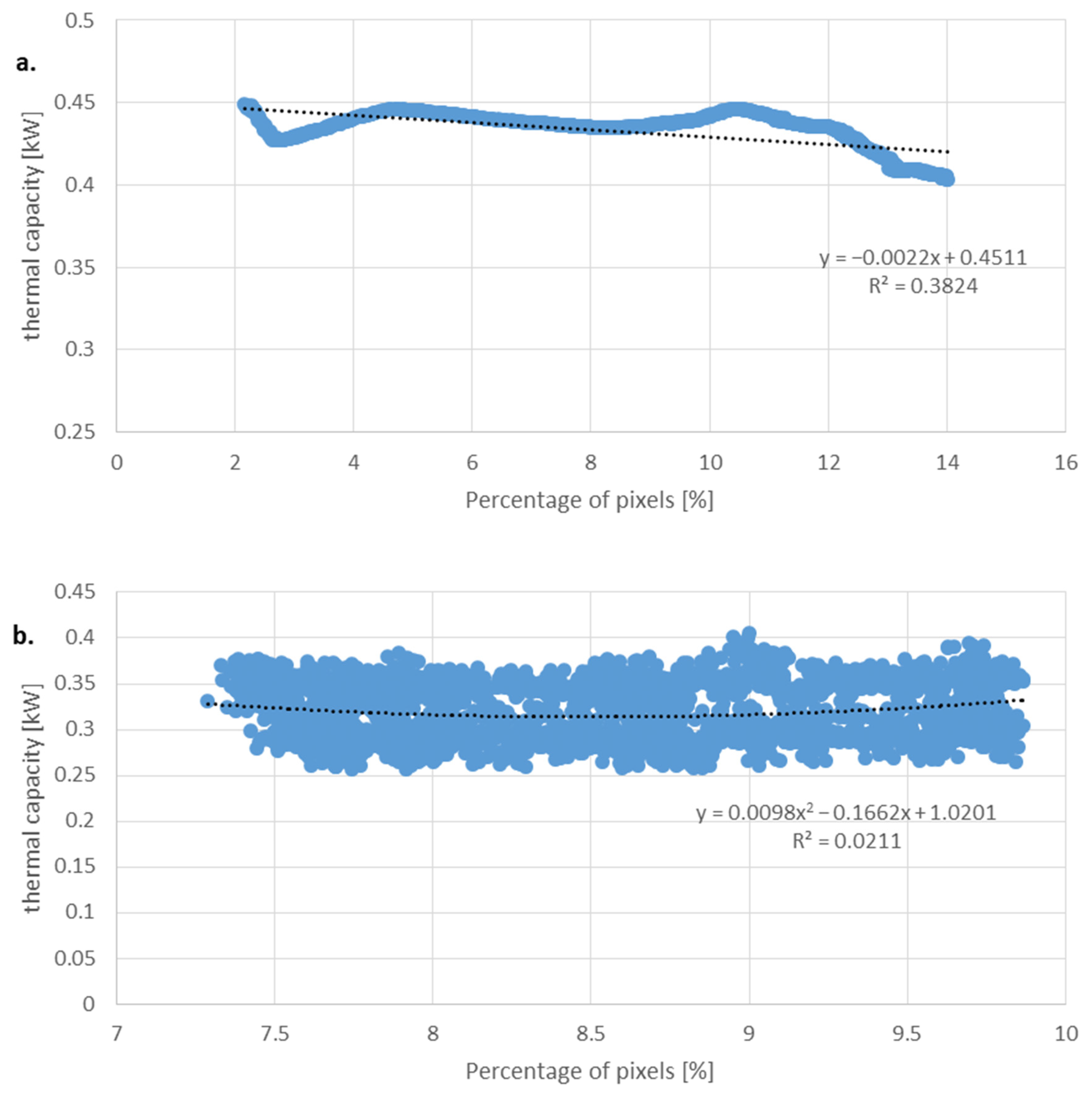
The relationship between the thermal capacity from four test series and the amount of frost is shown in Figure 14. This approximation was less accurate due to the fluctuations in the thermal capacity of the air cooler, which were as high as 0.1 kW. After the initial drop behind the inflection point (Figure 14b), the thermal capacity of the air cooler slightly rose with the increase in the amount of frost. This may have been an effect of the changes in the frost structure, leading to a decrease in its thermal resistance or the frost layer achieving a critical diameter.
The proposed method for this analysis allowed us to assess the degree of frosting and its impact on the operation of the air cooler on the basis of visual observation of the heat exchange surface during the long-term operation of the exchanger in the cooling chamber. This method also allowed us to determine the correlations describing the degree of frosting during the operation of the cooler. It was shown that the correlation between the degree of frosting and the measured thermal flow values was clearly visible, especially in the case of the air and glycol temperatures and the cooling capacity of the exchanger. It is necessary to determine all the quantities that are related to the frosting process. The basic parameters that were also included in the analysis are the temperature of the cooler fins and the flow of the cooling fluid (glycol).

5. Conclusions

Based on the presented results, the following conclusions can be drawn:
  • The proposed method of analysis allowed us to assess the extent of frosting formation and its influence on the thermal characteristics of the air cooler, which was based on the visualisation of frosting during the long-term operation in the cold storage chamber. The proposed approach made it possible to develop a correlation describing the relationship between frosting level and operation time.
  • The experimental results show a negative influence of frost formation on the air cooler. In a single working cycle, frost decreased cooler capacity by ca. 0.2 kW; however, in the long term, the capacity may drop by 40%.
  • The tested air cooler is characterised by a high bypass factor (BF), 0.55 on average. During frosting, the BF further increased. The highest value in the analysed timeframe achieved BFmax,fr = 0.73 (Equation (2)). This means that almost three-quarters of the air passing through the air cooler did not have contact with the heat-exchanging surface.
  • The results obtained using the presented method may be useful for quantitative evaluation of the operation of air coolers and optimisation or improvement of the defrosting process.
  • The proposed approach requires that the photographs of the tested air cooler should be taken in the same conditions, i.e., with the same lighting and position of the CCD camera. This will ensure that the same span of colours for all the analysed photographs will be maintained. Another phenomenon that might influence the results is the pixels counting algorithm of the frost surface structure at the beginning of defrosting.
  • The presented results are valid only for the tested air cooler. However, due to the similarity of air cooler construction, the proposed frosting level correlation may be usable during the design of other air coolers.

Author Contributions

Conceptualization, J.G. and D.B.; methodology, D.B. and P.J.; software, P.J.; validation, P.J., J.G. and K.Ś.; formal analysis, D.B.; investigation, K.Ś.; resources, D.B.; data curation, P.J.; writing—original draft preparation, P.J and J.G.; writing—review and editing, D.B and K.Ś.; visualization, P.J.; supervision, D.B. and J.G; project administration, P.J.; funding acquisition, P.J. All authors have read and agreed to the published version of the manuscript.

Funding

The current research was performed as a part of projects WZ/WM-IIM/1/2020 and financed with use of funds for science of MNiSW.

Institutional Review Board Statement

Not applicable.

Informed Consent Statement

Not applicable.

Data Availability Statement

Not applicable.

Acknowledgments

Not applicable.

Conflicts of Interest

The authors declare no conflict of interest.

Nomenclature

Aheat transfer surface area, m2
BFbypass factor
cspecific heat, J/(kg⋅K)
koverall heat transfer coefficient, W/(m2⋅K)
Q ˙ heat transfer rate, W
Rheat transfer resistance, m2⋅K/W
Sfrosting level
ttemperature, °C
V ˙ volumetric flow rate, m3/s
ρdensity, kg/m3
τdimensionless time
Subscript
cparameters of the cooler
frfrost conditions
gglycol
ininlet of the cooler
sfins surface
outoutlet of the cooler
1in front of the cooler
2behind the cooler
abefore inflection point
bafter inflection point

References

  1. Hundy, G.F. Refrigeration, Air Conditioning and Heat Pumps, 5th ed.; Butterworth-Heinemann: Oxford, UK, 2016. [Google Scholar]
  2. Hayashi, Y.; Aoki, A.; Adachi, S.; Hori, K. Study of frost properties correlating with frost formation types. J. Heat Transf. 1977, 99, 239–245. [Google Scholar] [CrossRef]
  3. Sami, S.M.; Duong, T. Mass and heat transfer during frost growth. ASHRAE Trans. 1989, 95, 158–165. [Google Scholar]
  4. Lee, Y.B.; Ro, S.T. Analysis of the frost growth on a flat plate by simple models of saturation and supersaturation. Exp. Therm. Fluid Sci. 2005, 29, 685–696. [Google Scholar] [CrossRef]
  5. Negrelli, S.; Hermes, C.J.L. A semi-empirical correlation for the thermal conductivity of frost. Int. J. Refrig. 2015, 58, 243–252. [Google Scholar] [CrossRef]
  6. Wang, W.; Guo, Q.C.; Lu, W.P.; Feng, Y.C.; Na, W. A generalized simple model for predicting frost growth on cold flat plate. Int. J. Refrig. 2012, 35, 475–486. [Google Scholar] [CrossRef]
  7. Kandula, M. Frost growth and densification in laminar flow over flat surfaces. Int. J. Heat Mass Transf. 2011, 54, 3719–3731. [Google Scholar] [CrossRef]
  8. Nascimento, V.S., Jr.; Loyola, V.R.; Hermes, C.J.L. A study of frost build-up on parallel plate channels. Exp. Therm. Fluid Sci. 2015, 60, 328–336. [Google Scholar] [CrossRef]
  9. Tahavvor, A.R.; Yaghoubi, M. Prediction of frost deposition on a horizontal circular cylinder under natural convection using artificial neural networks. Int. J. Refrig. 2011, 34, 560–566. [Google Scholar] [CrossRef]
  10. Leoni, A.; Mondot, M.; Durier, F.; Revellin, R.; Haberschill, P. State-of-the-art review of frost deposition on flat surfaces. Int. J. Refrig. 2016, 68, 198–217. [Google Scholar] [CrossRef] [Green Version]
  11. Getu, H.M.; Bansal, P.K. New frost property correlations for a flat-finned-tube heat exchanger. Int. J. Therm. Sci. 2011, 50, 544–577. [Google Scholar] [CrossRef]
  12. Amini, M.; Pishevar, A.R.; Yaghoubi, M. Experimental study of frost formation on a fin-and-tube heat exchanger by natural convection. Int. J. Refrig. 2014, 46, 37–49. [Google Scholar] [CrossRef]
  13. Seker, D.; Karatas, H.; Egrican, N. Frost formation on fin-and-tube heat exchangers. Part I—Modeling of frost formation on fin-and-tube heat exchangers. Int. J. Refrig. 2004, 27, 367–374. [Google Scholar] [CrossRef]
  14. Yan, W.; Li, H.; Wu, Y.; Lin, J.; Chang, W. Performance of finned tube heat exchangers operating under frosting conditions. Int. J. Heat Mass Transf. 2003, 46, 871–877. [Google Scholar] [CrossRef]
  15. Liu, X.; Yu, J.; Yan, G. An experimental study on the air side heat transfer performance of the perforated fin-tube heat exchangers under the frosting conditions. Appl. Therm. Eng. 2020, 166, 114634. [Google Scholar] [CrossRef]
  16. Padhmanabhan, S.K.; Fisher, D.E.; Cremaschi, L.; Moallem, E. Modelling non-uniform frost growth on a fin-and-tube heat exchanger. Int. J. Refrig. 2011, 34, 2018–2030. [Google Scholar] [CrossRef]
  17. Lee, S.H.; Lee, M.; Yoon, W.J.; Kim, Y. Frost growth characteristics of spirally-coiled circular fin-tube heat exchangers under frosting conditions. Int. J. Heat Mass Transf. 2013, 64, 1–9. [Google Scholar] [CrossRef]
  18. Cui, J.; Li, W.Z.; Liu, Y.; Zhao, Y.S. A new model for predicting performance of fin-and-tube heat exchanger under frost condition. Int. J. Heat Fluid Flow 2011, 32, 249–260. [Google Scholar] [CrossRef]
  19. Keryakos, E.; Toubassy, J.; Clodic, D.; Descombes, G. Frost Growth Investigation and Temperature Glide Refrigerants in a Fin-and-Tube Heat Exchanger. In Proceedings of the International Refrigeration and Air Conditioning Conference, Purdue, IN, USA, 11–14 July 2016; p. 1567. [Google Scholar]
  20. Wang, F.; Liang, C.; Yang, M.; Fan, C.; Zhang, X. Effects of surface characteristic on frosting and defrosting behaviors of fin-tube heat exchangers. Appl. Therm. Eng. 2015, 75, 1126–1132. [Google Scholar] [CrossRef]
  21. Pu, L.; Liu, R.; Huang, H.; Zhang, S.; Qi, Z.; Xu, W.; Zhou, J. Experimental study of cyclic frosting and defrosting on microchannel heat exchangers with different coatings. Energy Build. 2020, 22, 110382. [Google Scholar] [CrossRef]
  22. Reichl Ch Sandström, C.; Hochwallner, F.; Linhardt, F.; Popovac, M.; Emhofer, J. Frosting in heat pump evaporators part A: Experimental investigation. Appl. Therm. Eng. 2021, 199, 117487. [Google Scholar] [CrossRef]
  23. da Silva, D.; Melo, C.; Hermes, C.J.L. Effect of frost morphology on the thermal-hydraulic performance of fan-supplied tube-fin evaporators. Appl. Therm. Eng. 2017, 111, 1060–1068. [Google Scholar] [CrossRef]
  24. Śmierciew, K.; Kołodziejczyk, M.; Gagan, J.; Butrymowicz, D. Numerical modeling of fin heat exchanger in application to cold storage. Heat Transf. Eng. 2018, 30, 874–884. [Google Scholar] [CrossRef]
  25. Śmierciew, K.; Kołodziejczyk, M.; Gagan, J.; Butrymowicz, D. Numerical simulations of fin and tube air cooler and heat and mass transfer in cold storage. Prog. Comput. Fluid Dyn. 2018, 18, 325–332. [Google Scholar]
Figure 1. Photograph of the tested air cooler: (a) air outlet side, (b) air inlet side.
Sustainability 14 13731 g001
Figure 2. Location of the measurement sensors.
Sustainability 14 13731 g002
Figure 3. Photographs of temperature sensor locations: (a) air inlet temperature, (b) fin temperature measurement.
Sustainability 14 13731 g003
Figure 4. Photograph of the tested air cooler: (a) frosted cooler; (b) between the defrosting cycles; (c) after the defrosting process.
Sustainability 14 13731 g004
Figure 5. Photographs of processed air cooler: (a) before defrosting; (b) after defrosting.
Sustainability 14 13731 g005
Figure 6. Amount of frost formed at the air cooler surface.
Sustainability 14 13731 g006
Figure 7. Air temperature variations during test.
Sustainability 14 13731 g007
Figure 8. Glycol temperature variations during test.
Sustainability 14 13731 g008
Figure 9. Bypass factor before and after the defrosting process in subsequent cycles.
Sustainability 14 13731 g009
Figure 10. Cooling capacity variation of tested air cooler.
Sustainability 14 13731 g010
Figure 11. Reduction in the thermal capacity of the air cooler under frosting conditions in subsequent cycles.
Sustainability 14 13731 g011
Figure 12. Fin temperature variations during test.
Sustainability 14 13731 g012
Figure 13. Average pixels percentage of frost formation: (a) before the inflection point; (b) after the inflection point.
Sustainability 14 13731 g013
Figure 14. Relationship between pixel percentage of frost formation and thermal capacity of the tested air cooler: (a) before the inflection point; (b) after the inflection point.
Sustainability 14 13731 g014
Table 1. Thermal performance parameters of the tested air cooler during eight test series.
Before DefrostingAfter Defrosting
Q ˙ c , fr [W]kfr [W/(m2 K)]BFfr Q ˙ c [W]k [W/(m2 K)]BFΔRfr [m2 K/W]
145.8180.73249.2310.620.08
155.3120.66250.9190.490.13
153.2120.64215.8170.520.20
170.6120.66214.3150.510.32
181.1120.69247.1170.570.22
153.2110.63223.2170.510.18
223.1130.72277.6160.590.31
247.8210.72355.2300.600.11
Publisher’s Note: MDPI stays neutral with regard to jurisdictional claims in published maps and institutional affiliations.