Article

Durability Assessment of ETICS: Comparative Evaluation of Different Insulating Materials

by
Roberto Landolfi
* and
Maurizio Nicolella
Department of Civil, Architectural and Environmental Engineering, University of Naples Federico II, 80125 Naples, Italy
*
Author to whom correspondence should be addressed.
Sustainability 2022, 14(2), 980; https://doi.org/10.3390/su14020980
Submission received: 3 December 2021 / Revised: 31 December 2021 / Accepted: 4 January 2022 / Published: 16 January 2022

Abstract

:
The External Thermal Insulation Composite System (ETICS) is a common cladding technology that is widely used thanks to its well-known advantages. Despite previous studies dealing with ETICS durability in real-building case studies or involving accelerated ageing tests in climatic chambers, little progress has been made in the knowledge of the long-term durability of the system. In order to realize optimized maintenance plans for this component, the durability of the whole system, and of the most-used insulating materials for the ETICS (i.e., cork, polyurethane, rock wool, glass wool, grey EPS, and fiberfill wood), has been investigated. Based on previous experiments on ageing cycles, different climatic chambers were used to accelerate performance decay by simulating natural outdoor exposure in order to assess different physical and thermal characteristics (thermal transmittance, decrement factor, time shift, water absorption, thermal resistance, and conductivity). Recorded trends show that materials with lower thermal conductivity exhibit lower performance decay, and vice versa. The durability of the ETICS with different insulating materials (as the only variable in the different samples) was evaluated in order to quantify service life and then correctly plan maintenance interventions. Life-cycle assessment must take into account service life and durability for each material of the system. A higher durability of insulating materials allows for the execution of less maintenance interventions, with the loss of less performance over time. This study shows the physical and thermal behavior of the ETICS during its service life, comparing the differences induced by the most-used insulating materials. As a result of accelerated ageing cycles, the analyzed ETICS reveals a low grade of decay and measured performances show little degradation; for thermal conductivity, differences between the measured and the declared conductivities by technical datasheet were observed.

Graphical Abstract

1. Introduction

1.1. Building Sector and Energy Efficiency Developments

The reduction of energy consumption and the environmental impacts of any productive activity are two of the most critical challenges of sustainable human development.
It is known that the use of buildings and the construction sector accounted for 36% of final energy use [1].
Moreover, around 77% of the global final energy demand in buildings is for heating and cooling end-uses, including space heating and cooling, water heating, and cooking. The only remaining final energy demand in buildings (23%) is for electrical end-uses, including lighting and appliances.
Buildings and the construction sector are together responsible for 39% of all carbon emissions in the world, with operational emissions (from energy used for heating, cooling, and lighting) accounting for 28%. The remaining 11% comes from embodied carbon emissions, or ‘upfront’ carbon associated with materials and construction processes throughout the whole building lifecycle [2].
The European Commission estimates that 40% of EU energy consumption and 36% of greenhouse gas (CO2) emissions come from buildings and therefore the building sector is the single largest energy consumer in Europe [3]. In December 2019, the European Union formulated a new growth strategy, intending to transform itself into a modern, resource-efficient, and competitive economy.
The achievement of net zero greenhouse gas emissions by 2050 is one of the most important European-set targets to accomplish its commitment to the Paris Agreement, although 97% of building housing stock must be modernized to achieve it [4,5] and, in particular, 75% of building stock is energy inefficient and is required to be renovated to a higher energy efficiency class [5].
Holistic retrofits can achieve 50–90% of the final energy savings in thermal energy-use in existing buildings, with the cost savings typically exceeding investments [6].
In Italy, in recent times, the transposition of the EU directives and framework of decisions led the Italian legislation to promote energy efficiency trends, policies, and measures focusing on legal acts updating the minimum requirements for buildings, building components, and technical building systems. Furthermore, it provides the evaluation model for heating, cooling, and lighting systems and defines guidelines for energy performance certification. Moreover, the introduction of a tax reduction raised a large number of energy-retrofit interventions, with thermal insulation, such as external thermal composite systems, recently becoming the most important feature contributing to the comfort and overall energy efficiency of buildings.
The ETICS is the best solution for the thermal insulation of buildingsexterior walls and/or cladding in new constructions as well as renovations; this technology allows for the reduction of final energy consumption, ensuring savings in thermal energy-use. In spite of its importance, there has been little research on the durability of the system and its decay.
This article is part of a wider research, the purpose of which is to study the behavior of the ETICS during service life and to evaluate the main factors leading to failures. More specifically, this paper focuses on ETICS durability by means of accelerated laboratory ageing cycles in order to evaluate the characteristics and performances of ETICSs over time, including thermal resistance, time shift, decrement factor, water absorption, tensile strength perpendicular to faces, compressive strength, impact resistance, and surface degradation.
Paragraph 1.2 introduces the ETICS and its characteristics, then paragraph 1.3 illustrates the state of the art, dealing with ETICS durability.
In the research, Section 2, investigates ETICS decay through accelerated ageing cycles in climatic chambers simulating natural outdoor exposure. Here, the role played by the insulating material for the durability of the ETICS is described, analyzing the most important performances of the six samples realized by keeping the same stratigraphy while varying the insulating materials among the most-used insulating materials for ETICSs, i.e., grey expanded polystyrene, wood fiberfill, polyurethane, cork, glass wool, and rock wool.
In Section 3 the most relevant and suitable performances of ETICSs are examined, i.e., thermal resistance, time shift, decrement factor, and water absorption. The first three requirements are the most important ones because they are directly related to thermal performance, whereas the fourth one has a great influence on system degradation. Although the others requirements, the mechanical ones, will be analyzed for further developments, the most important aforementioned performances are measured and exposed in Section 4.

1.2. ETICS

External Thermal Insulation Composite Systems (ETICSs) are a common cladding technology, widely used for its well-known advantages, such as the decrease of global thermal loads, increase of thermal inertia of the envelopes, and elimination of thermal bridge effects. Moreover, the easy and quick application with renders makes it the best solution to obtain an energy-efficient building, both for recovery interventions and new building projects. In fact, it allows thinner external walls and the possibility of installation without disturbing the building’s dwellers, increasing the durability of the facades and providing a finished appearance similar to traditional rendering.
ETICSs are not a new technology. In fact, it has existed since 1960, created by E. Horbach, who obtained a patent on an EPS-based ETICS in Germany [7]. Horbach’s patent has been credited with implementing the use of polymer-based stucco reinforced with alkali-protected glass fiber mesh over expanded polystyrene insulation.
In North America (Canada and USA) these systems are called Exterior Insulation Finish Systems (EIFS), while in Ireland and the United Kingdom they are called External Wall Insulation Systems.
ETICSs are a kit in the sense of the Construction Products Regulation (CPR), consisting of prefabricated components applied directly to the façade onsite [8]. According to UNI/TR 11715 and EAD 040083 shared terminology, the aforementioned components, that perfectly fit together because of their system holder-tested design, are:
  • Adhesive;
  • Insulation products;
  • Mechanical-fixing devices;
  • Rendering systems, typically consisting of a base coat, reinforcement—glass fiber, and a finishing coat/decorative coat;
  • Secondary materials (any supplementary component/product used to form joints or to achieve continuity).

1.3. Research Issue

Currently, one of the most important global challenges is sustainable development. Efforts have been made to improve the quality of the environment (Treaty of Amsterdam) and to fulfill ecological objectives, avoiding the overexploitation of natural resources, environmental degradation, and pollution.
The EU directives aim for European countries to establish requirements for the sustainable design of green products and to promote the use of common methods to measure and communicate the life-cycle environmental performance of products [9]. In the building sector, life-cycle assessment has become crucial and, in this perspective, LCA must take into account service life and durability for each material. So, in the whole life cycle, service life has the greatest environmental impact.
Recently, more and more attention has been paid to the durability problems of building components. In fact, it is important to increase the lifetime durability of building components as it reduces maintenance costs and even renovation costs, reducing environmental impact and promoting sustainability.
Naturally, this point raises questions about the durability of the ETICS, the most common cladding building technology, which leads to the necessity of carrying out life-cycle assessment and life-cycle cost analysis.
As defined in the ISO code 15686 [10], service life is the period, after installation, during which the building or its parts maintain performance levels higher than or equal to the acceptance limits. The methodological approach, well-specified in the ISO 15686-3 code, consists of points taken as follows:
  • The definition of users’ needs, involving technological requirements within the stress context (type and intensity of the agents). The target of this section is to define the requirements of building components and related required performance;
  • The identification of degradation mechanisms and effects, and the choice of measurement criteria for functional and performance characteristics technology;
  • Exposure and measurement. This is the phase in which ageing tests are performed, both natural (long-term exposure) and accelerated (short-term exposure), and in which the effects of the agents on the building components are measured (degradation);
  • The analysis and interpretation of results. Analyzing the results obtained through experimentation (in terms of performance over time), the service life of a component, under certain stress conditions, is assumed.
This approach analyzes degradation mechanisms based on component requirements and related performance decay.
According to the ISO code 15686, some studies show the modalities of the performance decay of a generic building component, which may allow the construction of performance/time curves [8].
Although the scientific literature commonly evaluates building component service life by means of performance decay assessments, for the ETICS this approach has been performed for only a few years.
Previous studies investigated ETICS durability, some of which dealt with long-term investigations of naturally aged samples in existing-building case studies, among others involving short-term investigations of accelerated ageing in climatic chambers. It is well known that accelerated ageing has a great advantage because of the possibility to obtain results quickly, compared to gradual exposure to natural atmospheric agents.
Among the previous studies, Swedish research, consisting of a survey of 821 buildings, shows that moisture, resulting from the poor connections of windows and doors, is primarily responsible for the decay of joints and fixing devices—wetting the materials inside the stud wall and causing mold growth [11]. On the surface of the wall, hidden damages are never visible, but they require quality assurance where there are window installations and service details.
Another study, carried out by Lisø et al. [12], analyzed building defects in order to obtain further develop solutions and preventive measures ensuring high-performance building envelopes. In that case, the estimated sample took into account the vertical elements of envelopes, and the ETICS included 6% of defect cases analyzed in relation to the external walls. Moreover, in this dissertation significant attention was paid to methods for assessing the impacts of external climatic agents at a local scale on building envelopes [12,13].
An interesting study combined the two types of methods; field investigations dealing with 61 buildings with ETICS cladding and laboratory experiments processing samples exposed to accelerated climate ageing from 4 to 48 weeks [14].
By evaluating field observations, the first part of this survey presents the most prevalent causes of defects for ETICSs recorded in the period from 1993 to 2017 in Norway. A total of 150 causes of defects were recorded for 61 real-building investigations. These included defects associated with flashings against precipitation, incorrect reinforcement mesh, insufficient thickness of render, a default render mix in undesirable setting conditions, shrinkage and temperature movements in the render, incorrect end laps against adjoining structures, faulty anchorage of the system, microorganism growth in/on the render, variations in render thickness over the insulation boards, vibration movements in the substructure, settling, incorrect choice of paint or incorrect cleaning prior to painting, insufficient impact resistance, lack of pigment, and mold growth behind the ETICS.
In the second part of the same research, short-term durability investigations were achieved with the accelerated ageing exposure of a large number of samples (19 different ETICSs) with different thermal insulating materials (EPS, mineral wools, and polyisocyanurate).
Moreover, small samples (0.7 m × 0.6 m) as well as big samples (2.4 m × 1.3 m) were tested, evaluating the possibility of cracking and defects associated with the installed window as well.
Despite such interesting findings, the effect on the substrate was neither tested nor examined, so further observations are needed in order to evaluate other performance decays, separate from visual observations.
Another fieldwork study carried out a statistical survey on the pathology, diagnosis, and rehabilitation of ETICSs in various areas of Portugal [15]. The adopted methodology consisted in the visual inspection of 146 façades with ETICS cladding aged from 3 to 22 years for the creation of classification lists of anomalies, most-likely causes, diagnosis methods, and repair/maintenance techniques. Based on the data collected for this statistical survey, the study identified the most common anomalies, such as biological growth (present on 55.5% of the façades inspected), other color changes (48.6%), and rain action (43.2%). Therefore, even this study is limited by visual inspection as the only performance decay observed and shows how the most common anomalies belong to group color/aesthetic anomalies, which is not usually associated with direct consequences in terms of thermal capacity. Furthermore, this analysis highlights the importance of a correct maintenance plan to prevent premature degradation due to environmental and external mechanical actions during service life. Anomalies in ETICSs can be prevented by the proper design, application, and choice of appropriate materials, especially breakage anomalies and façade flatness anomalies, demonstrating the importance of design and maintenance stages for ETICS service life.
Further observations, with a focus on an ETICS case study in the interior of Portugal, were made, with extreme weather conditions causing stressful environments for ETICSs [16]. The tested ETICSs, consisting of polystyrene XPS panels applied on a brick masonry, are analyzed taking into account the occurrence of cracks along the rigid thermal insulation joints. Moreover, the dynamic hygrothermal and mechanical behaviors of the wall were analyzed, considering the climatic conditions, the characteristics of the thermal insulation plates, as well as the support/bonding and finishing layer conditions. Interesting findings were achieved using the PATORREB building pathology catalogue, with relevant contributions to the knowledge of ETICSs, and of “past mistakes”, such as the use of polystyrene XPS as thermal insulating panels in vertical envelopes in critical climatic conditions. Furthermore, this study, as well as others, highlighted the importance of a correct maintenance plan, of a correct design, and of the correct application and choice of materials.
Among the latest studies, many researchers have questioned satisfactory long-term ETICS durability by analyzing building products subjected to appropriate accelerated ageing in laboratory.
In Finland, some researchers studied the main climatic exposures and how these can be reproduced in laboratory tests within a relatively short time frame compared to the natural ageing of the outdoor climate. This study provided examples of ageing methods, of climate ageing laboratory equipment, and of building-product properties to be tested before, during, and after ageing [17].
A new calculation method for estimating accelerated ageing related to natural outdoor climate exposure was developed [18]; materials and components used for building envelopes were exposed to UV light, heat radiation, water, and frost during the testing of new building solutions.
Research carried out by Bochen assessed the behavior over time of external mineral plasters and then of ETICS external render; the measured performance was the change of porosity [19,20,21,22]. This method developed an accelerated ageing test involving UV, heat and cold cycles, and freeze and thaw cycles, evaluating the evolution over time of open capillary porosity. In this first laboratory test, artificial climatic factors were reproduced by a rotational method within different climatic chambers, each of which reproduced different agents. Major improvements were made over a similar method (the Northerst NT Build 495:2000 [23]) which uses a rotation chamber for the accelerated ageing simulator. This method was carried out in North Europe in most of the studies [14,18] and consists of an apparatus in which specimens can be rotated within four different climate zones.
In a Baltic States context, interesting findings were observed on painted façades by means of both types of durability tests, natural weathering, and artificial accelerated ageing in a climatic chamber [24]. Although it did not concern the whole ETICS, it dealt with paints, the performances of which are strictly related to water absorption, and thus this became the only measured parameter (a few studies were concerned with performances different from optical-visual observations). Moreover, in addition to the usual cycles such as UV radiation, temperature impacts, heating and drying cycles, and freeze and thaw cycles, it took into account fog pollution during rain cycles by means of acid–water solution spraying.
Other studies took place in Italy where researchers focused on the evolution of decay in ETICSs and on the proportion between natural exposure and accelerated ageing cycles [25]. After the analysis of the weather data in the city of Milan and the design of ageing data cycles, it was possible to establish which agents had to be included, and their intensity and frequency [26]. This phase produced important findings to evaluate the reference service life by using the analysis of the reference climatic condition [27]. Based on the ISO code 15686-2 [11], a comparison between degradation produced with artificial accelerated ageing and degradation produced with short-term outdoor exposure was possible, providing a useful ratio (the so called “re-scaling factor”) [26].
Although this aforementioned methodology was one of the most complete and valid, other approaches follow the ETAG004 [28] hypothesis, defining a generic North Atlantic context without taking into account the specific climatic context. The method was used to design short-term laboratory-accelerated ageing tests by mean of the cycles as follows: UV cycles; winter cycles involving rain, freeze, and thaw; and summer cycles involving dry heat and rain [29]. The study exposed to these accelerated laboratory ageing cycles a sample of the ETICS on a masonry wall. In order to evaluate hygrothermal performances, before and after ageing, degradation was assessed by a decay evaluation of the following performances: estimation of optical photographs by mean of the ISO 4628 standard [30], thermal transmittance, decrement factor, and time shift. One of the most interesting parts of this research is the methodology, which allows the assessment of the last two performances, by means of specimen as a door of the climatic chamber, achieving a detailed characterization of thermal performance.

2. Materials and Methods

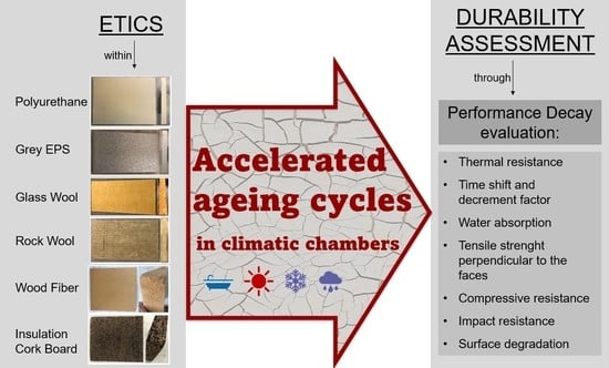
2.1. Insulating Materials

This experimentation expands the aim of the research, starting from the aforementioned research [29] and providing a relative comparison on the role played by the insulating material itself in determining the durability of an ETICS.
The reference for the investigation of all the insulating materials for the ETICS is the UNI/TR 11715 code [31], a technical report that includes a complete list of all the thermal insulation products, i.e., cellular glass; mineral wools such as rock, wool, and glass wool; expanded polystyrene; extruded expanded polystyrene; polyurethane; wood fiberboard; cork; and polyester fiberfill.
This research investigates the most widely used and well-performing materials for vertical envelopes such as:
  • Polyurethane (PU);
  • Grey expanded polystyrene (EPS);
  • Glass mineral wool (GW, named according to EN code 13162);
  • Rock mineral wool (MW, named according to EN code 13162);
  • Cork (ICB, insulation cork board, according to the reference code EN 13170);
  • Wood fiberboard (WF).
Specimens were prepared according to EAD 040083 [32]. Considering that the main objective of the research is to provide a relative comparison of the role played by the insulating material for the durability of an ETICS, six samples were realized by keeping the same stratigraphy while varying the insulating material among grey expanded polystyrene, wood fiberfill, polyurethane, cork, glass wool, and rock wool. Therefore, 6 kinds of samples were packaged for each insulating material (EPS, WF, PU, ICB, GW, and MW) using the same ones for the other layers.
Each specimen was realized with the following characteristics:
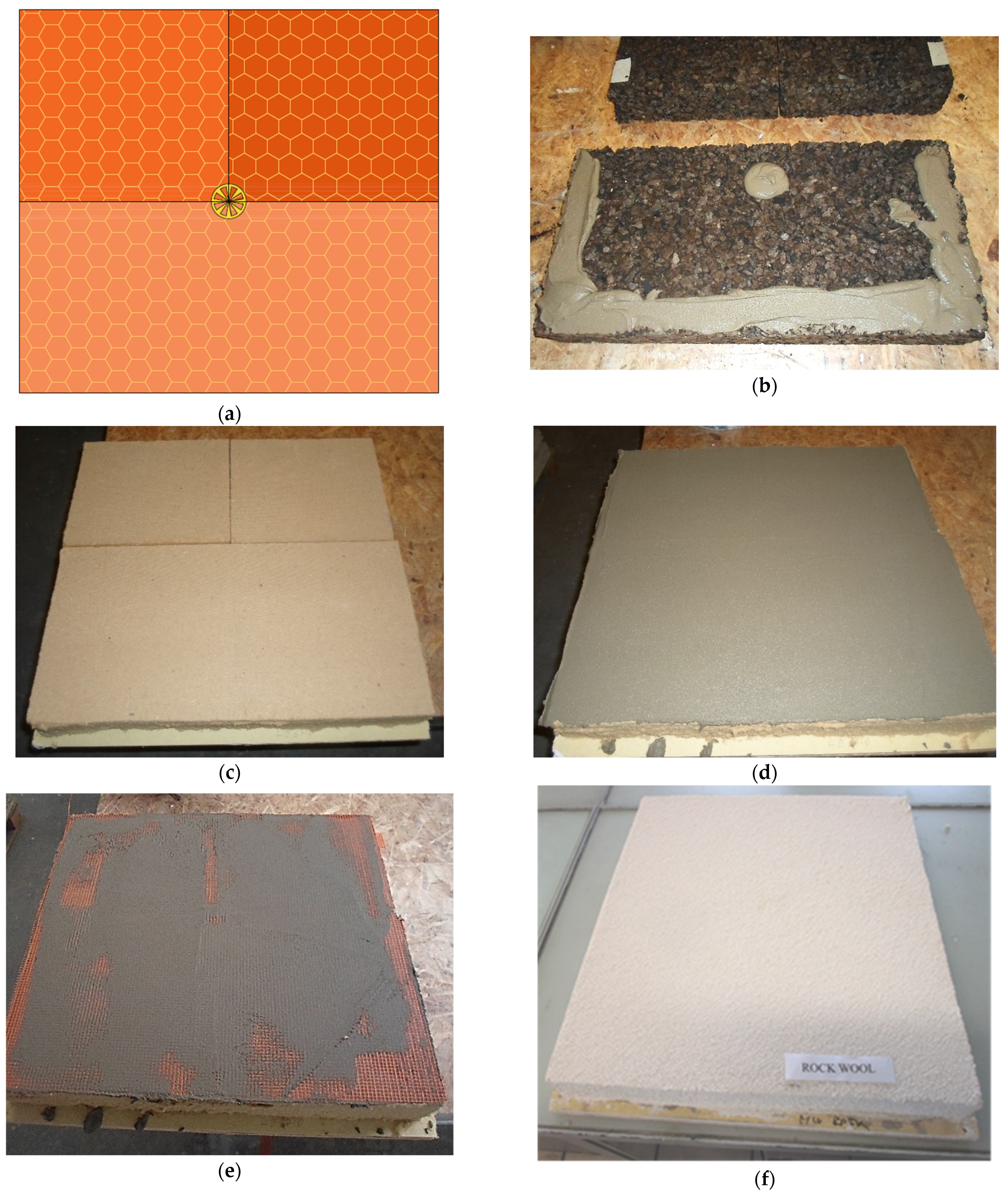
  • Support of wooden OSB (oriented strand board; thickness = 2 mm) and outdoor plasterboard panel (thickness = 12.5 mm) instead of masonry wall, because the aim of the research is focused on the interaction between an ETICS and environmental loads, and not on the back support, which does not have any kind of influence on the durability of the system;
  • Skim-coating adhesive (a mineral adhesive/skim coat in powder form made of unsaponifiable resins), high-resistance Portland cement, and selected sands with a maximum particle size of 0.6 mm;
  • Thermal insulating material with different widths as a consequence of the different conductivities, as specified in Table 1, in which the system name refers to commercial name of the company which has provided materials; the target value of thermal transmittance has been chosen in compliance with Italian law requirements (D.M. 26 June 2015), considering the hypothesis of a double-brick wall with internal cavity;
  • Base coat with embedded reinforcing fiberglass mesh; the base coat material is the same skim-coating adhesive;
  • Finishing coat. A coating based on acrylic resins in dispersion within additives that facilitate application and formation of a film, as well as marble granules and quartz sand with controlled absorption—max particle size 1.2 mm.
Uc and Rc were calculated through the formulas for thermal transmittance and resistance, based on the declared value of thermal conductivity λD.
The glass fiber mesh was turned round the edges of the specimen, thus five faces of insulating panels were covered by the whole rendering system (base coat, glass fiber, and finishing coat).
All materials and accessories were provided by IVAS spa, international leader in industry operating in building finishes, offering products, solutions, systems, and integrated technologies in the construction market according to its certified systems within the main insulating materials producers.
The manufacturers of insulating materials were selected based on the reliability demonstrated in recent years and, where possible, on the presence of the ETA certification of the whole ETICS (which represents a distinctive element for the qualitative evaluation of an ETICS).
The other most significant physical parameters of the investigated materials are listed in Table 2.
Unlike other previous studies, big samples were used measuring 55 × 60 cm because they were used as the door of a climatic chamber.
Every specimen was built with 3 insulation panels in order to reproduce one T joint in the middle of the sample where a mechanical fixing device was placed (Figure 1). Insulating panels were cut and turned to avoid overlapping the borders. The scientific literature and common professional experience show damages at first, especially in correspondence of the T joints; that is why it is interesting to study these points. Then, as shown in Figure 1, the whole specimen was mechanically fixed and bounded, and then it was cured for 28 days before testing.

2.2. Pre-Designing Ageing Cycles

The aim of this phase is to look for the critical agents and intensities of ageing factors by which the system is stressed. First of all, in order to assess the influence of different distributions of ageing factors for an ETICS, it was necessary to decide which agents to consider in the accelerated ageing procedure, and their intensity.
Not taking into account environmental pollution (considering that the focus is on the performance decay of the insulation panel and not on finishing), UV radiation, mold growth, and wind uplift, the ageing cycle is composed as follows:
  • Summer and winter thermal shocks;
  • Freeze–thaw cycles;
  • Driving rain;
  • Cyclic variations in temperature and relative humidity.
UV degradation generally affects surface discoloration [33]; as such, it does not affect the physical and mechanical properties analyzed in this study.
Therefore, according to a previous study [22], it was found that the relevant agents for this building component are the ones of the aforementioned list, and it was shown that, in a short ageing process, it is possible to take into account only the frequency of events over a critical threshold. Finally, it is possible to weigh critical events by use of the EAD 040083 model, which simulates the real behavior and stress of ETICSs under defined conditions.

2.3. EAD 040083 Procedure for Investigation of ETICS Durability

For products not belonging to a harmonized standard according to the Construction Products Regulation (CPR) [34], if the manufacturer has chosen to declare performance, they can use a European Assessment Document (EAD) to get a European Technical Assessment (ETA) by a designated technical assessment body (TAB) affixing the CE marking.
ETA is a quality code and represents a distinctive element for the qualitative evaluation of an ETICS requested by manufacturers.
The reference EAD for ETICS is EAD 040083, a technical guide for ETICS property assessment, which tests, through a pre-established test program, the components organized in a specific thermal insulation system, in order to verify all the main characteristics and performances.
EAD defines test methods to verify performances corresponding to requirements considered essential according to European Construction Products Regulation n° 305/11 by means of standardized laboratory tests. Tests verify specific performances according to detailed, specified, and standardized procedures developed since UNI, EN, and ISO references.
Furthermore, Chapter 2.1 of EAD 040083 identifies ETICS-specific requirements, the same as the European directive’s requirements. This chapter lists testing methods to determine the various performances of the products and of the entire thermal insulation system and specifies the minimum sustainable values for use for each requirement.
The third requirement (hygiene, health, and environment, Chapter 5.1.3 of EAD 040083) is verified with tests that take into account hygrothermal behavior in accelerated ageing tests.
Even the EAD code 040427 [35], in Chapter 2.6, deals with accelerated ageing behavior introducing durability as one of the most important requirements of whole system. Then, in Annex D, it deals with accelerated ageing procedures. Considering that research task investigates ETICS durability, the most suitable methodology used accelerating ageing procedures by means of EAD 040083.

2.4. Designed Accelerated Ageing Cycles

In order to get an ageing cycle suitable for a generic climatic context, EAD 040083 [32] has analyzed ETICS decay factors and mechanisms. Thus, this study adopts the EAD 040083 method as it designs ageing cycles similar to the EAD and ETAG ones. Annex D lists two types of accelerated ageing tests:
  • A Hygrothermal behavior test which includes heat–rain cycles and heat–cold cycles, Section 2.2.6 of EAD 040083: water tightness of the ETICS: hygrothermal behavior);
  • Freeze and thaw behavior test, Section 2.2.5.1 of EAD 040083.
This research, considering the purpose of investigating ETICS decay according to Annex D.3 of EAD 040083, proposes the combined hygrothermal and freeze-and-thaw cycles test, that represents conditions that are widespread in all of Europe.
The research undertakes this EAD methodology with minor variations in order to reproduce real outdoor exposure seen over years.
Although the aforementioned EAD standard methodology perfectly fits with ETICS-behavior assessment during a lifetime, it was limited by EAD targets which require only the correspondence with the basic requirements of the European regulations and directives, including the Construction Products Regulation (CPR). Further observations are needed to study ETICS durability and investigate service life. Since the study deals with slowly ageing materials for evaluating ETICS behavior during service life comparatively in reasonable time, the research sets itself apart from the EAD approach because it sets a longer-term investigation target in accelerated ageing tests, expanding the aforementioned EAD cycles to cycles which exeed EAD limits.
According to the EAD, the cycles were designed as follows:
  • A total of 80 heat–rain cycles. Each cycle takes 6 h and consists firstly in heating to 80 °C (rising for 1 h) and maintaining at (80 + 5) °C for 2 h (total of 3 h), then spraying for 1 h with 1.5 ± 0.5 L/m2 min amount of water and water temperature at 15 ± 5 °C, and thirdly leaving for 2 h for drainage at 20 ± 5 °C;
  • A total of 7 heat–cold cycles. Each cycle lasts 24 h, comprising an initial exposure of 8 h to −10 ± 2 °C (fall for 2 h), then 9 h to 70 ± 2 °C (rise for 1 h) and maximum 30% RH, and finally exposure of 7 h to −10 ± 2 °C (fall for 2 h);
  • A total of 15 freeze–thaw cycles. Each cycle lasts 24 h, comprising an initial exposure for 8 h to water at 23 ± 4 °C by immersion of the specimens, with the skin submerged in a water bath according to the method described in EAD 040083 Section 2.2.7 [32], then, freezing to −20 ± 5 °C for 14 h, and a final insertion in the stove at +50 °C for 2 h.
Table 3 lists the chamber air conditions.

3. Decay Assessment

Compared with other studies, the proposed methodology for decay assessment takes into account a wider typology of performances. Basing on the previous literature dealing with ETICS decay analysis, this study aims to analyze the most suitable and measurable performances, i.e.,:
  • Thermal resistance;
  • Time shift;
  • Decrement factor;
  • Water absorption;
  • Tensile strength perpendicular to faces;
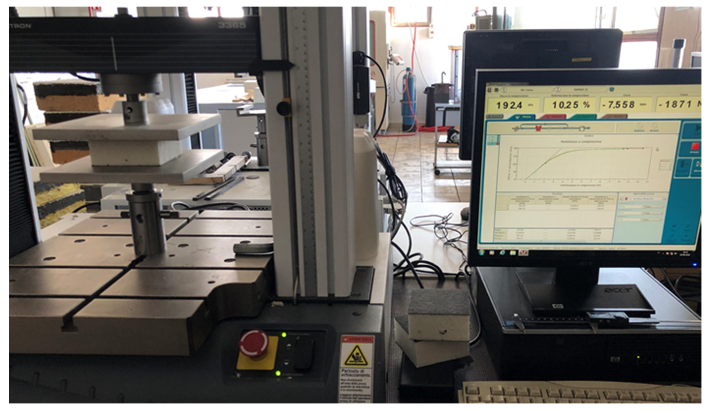
  • Compressive strength;
  • Impact resistance;
  • Surface degradation.
The first three requirements are the most important ones because they are directly related to thermal performance. Considering ETICSs were created to improve building thermal performance and energy efficiency, thermal resistance, time shift, and decrement factors are the only three performance indicators which evaluate the thermal requirement.

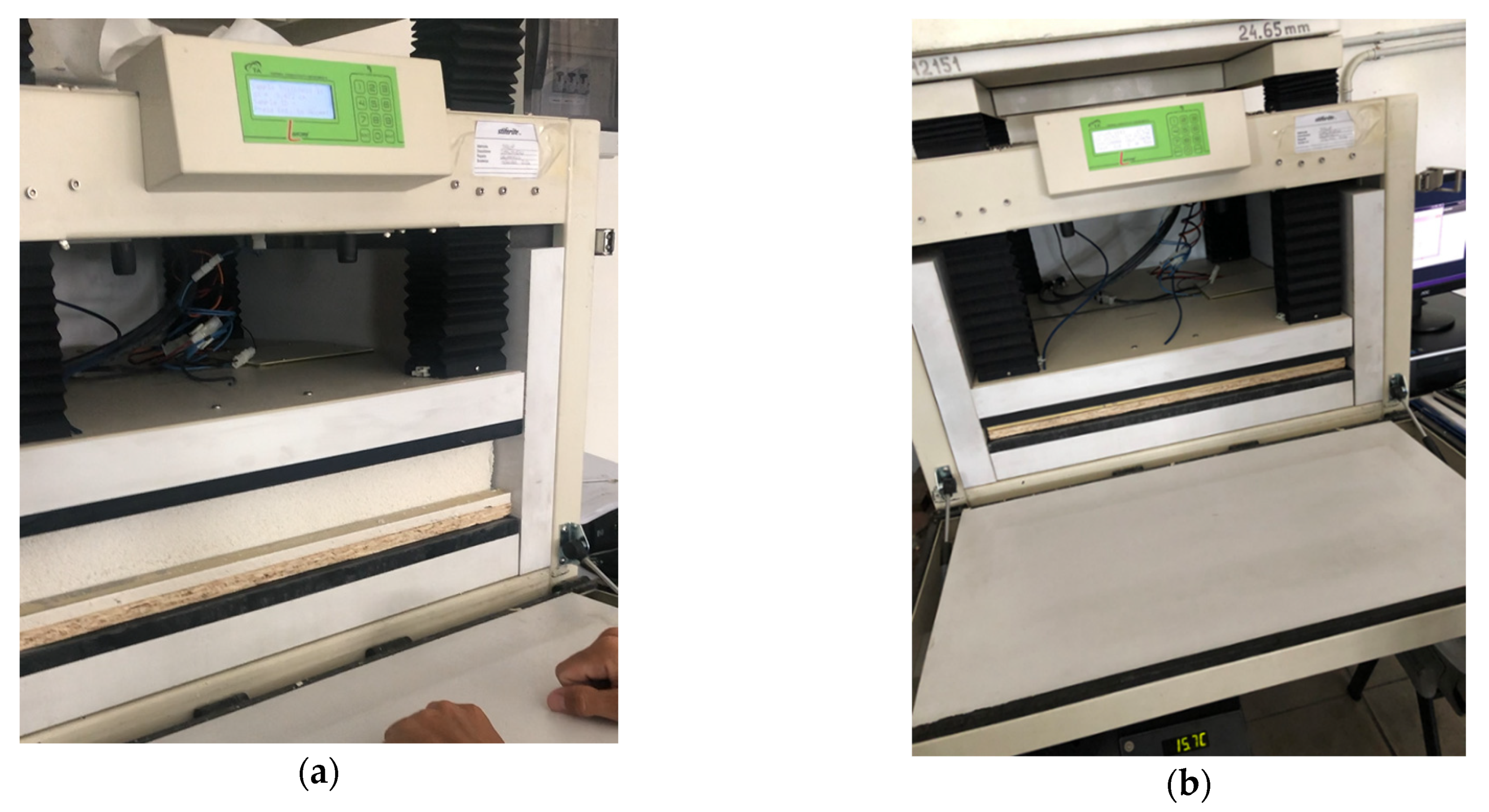
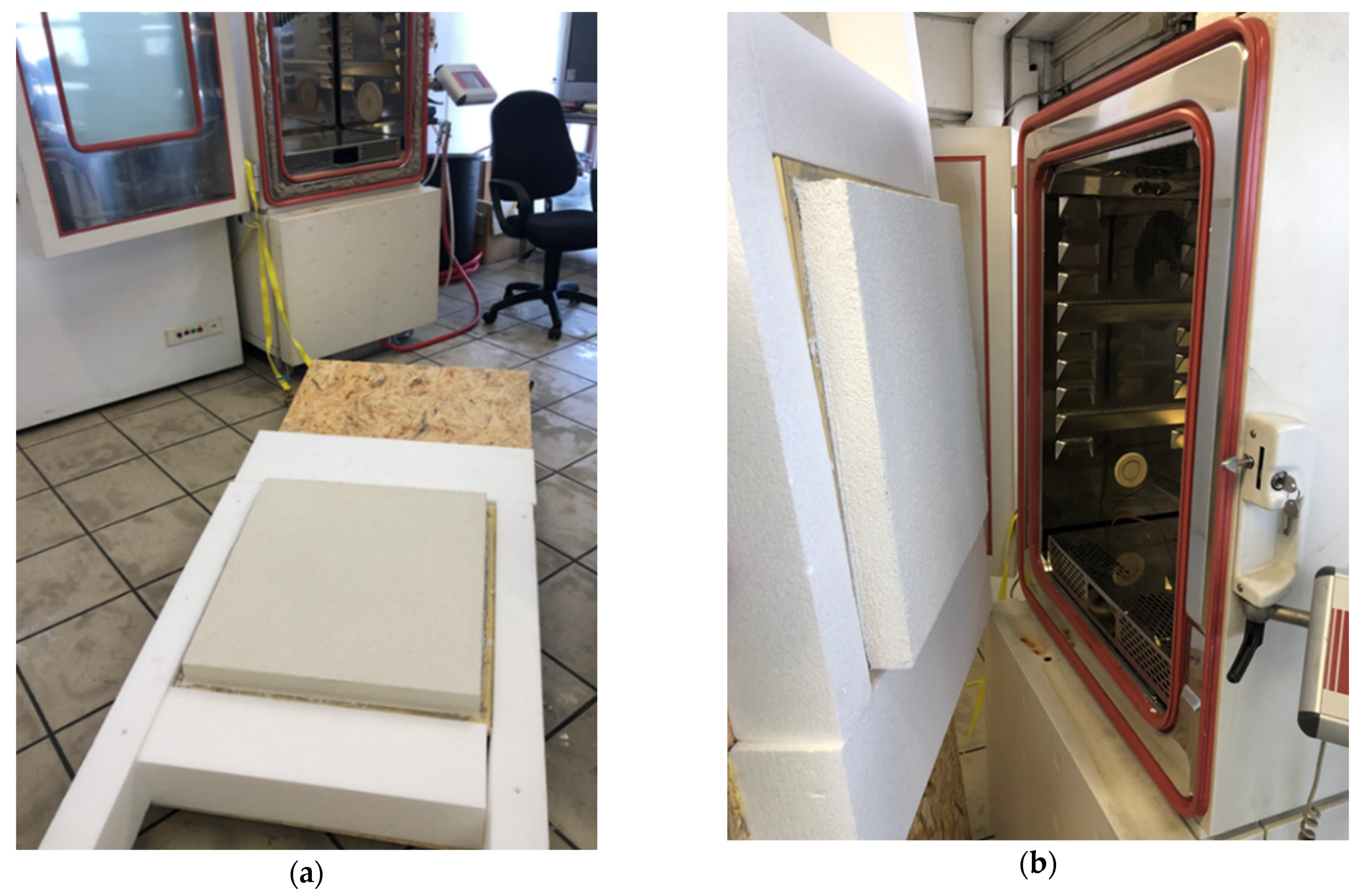
3.1. Thermal Resistance/Transmittance

According to the EN 12667 [36], thermal resistance is determined by means of a guarded hot plate and a heat flow meter method. The whole sample is placed inside the standard equipment with flat and parallel sides as shown in Figure 2.
When investigating the performance of thermal insulating materials, the main reference parameter is thermal conductivity, which is inversely proportional to the thermal resistance according to Formula (1) based on EN code 6946 [37]:
R = 1 h i + Σ s n λ n + 1 h e
The adopted procedure (EN 12667) evaluates thermal resistance, from which the conductivity of single materials of the stratigraphy is calculated.

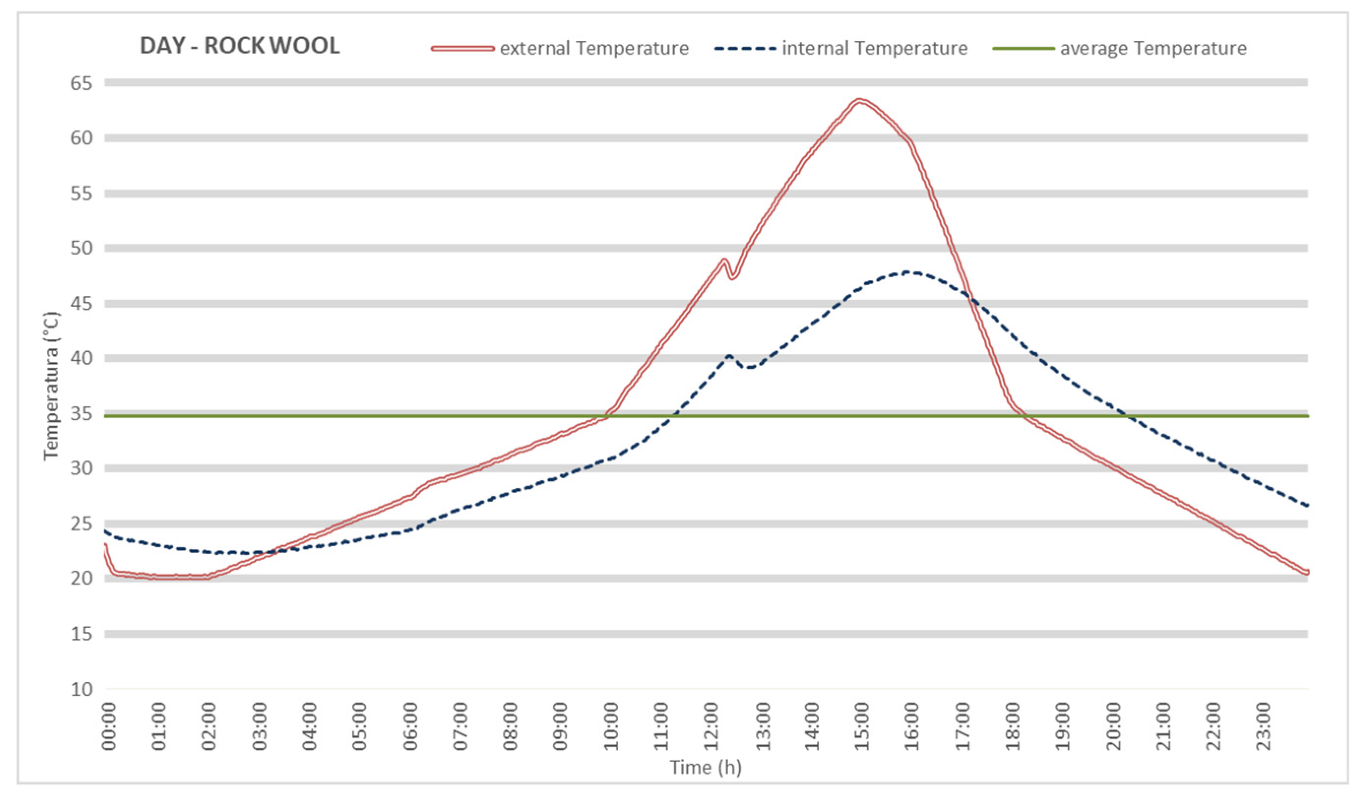
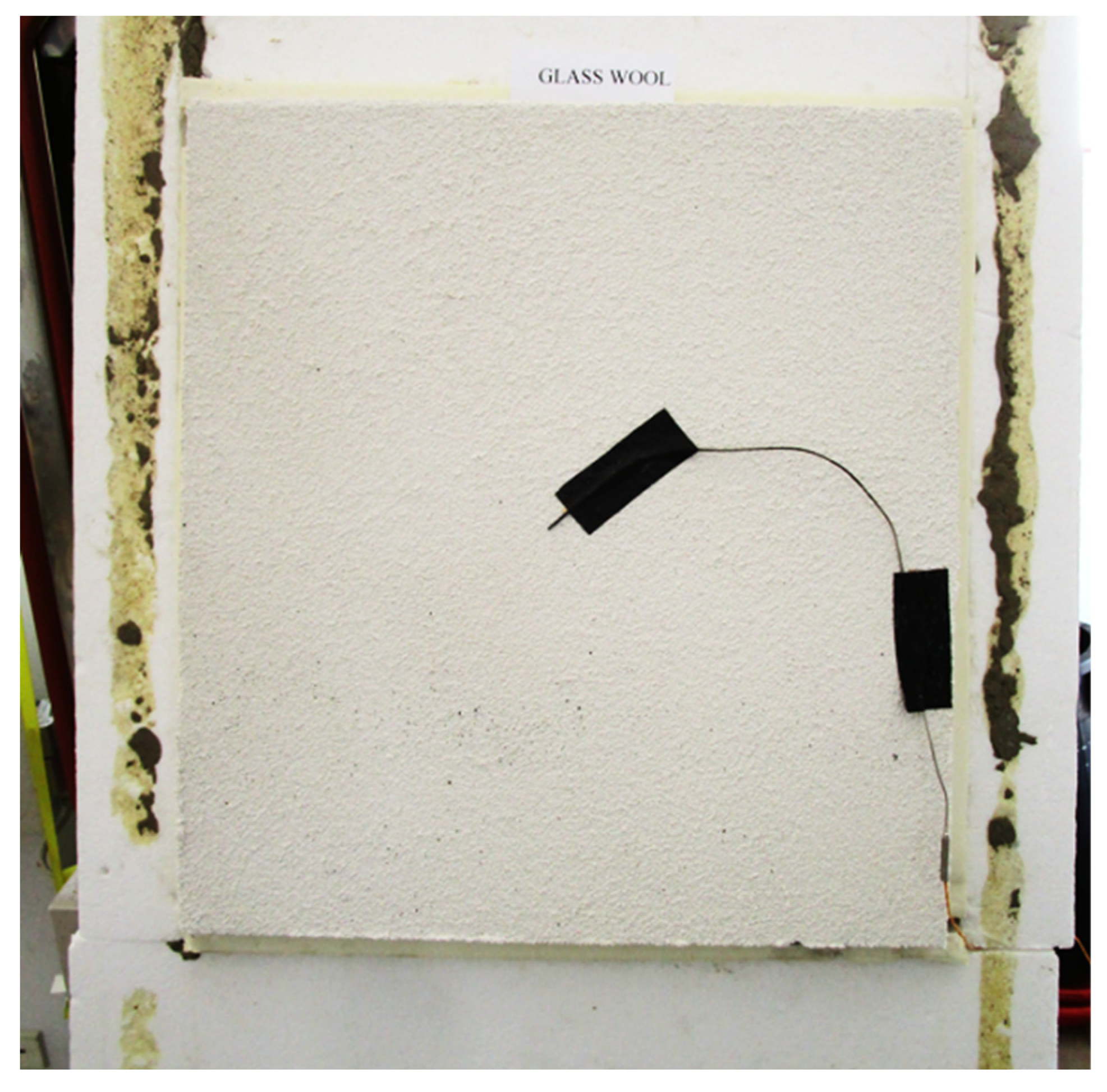
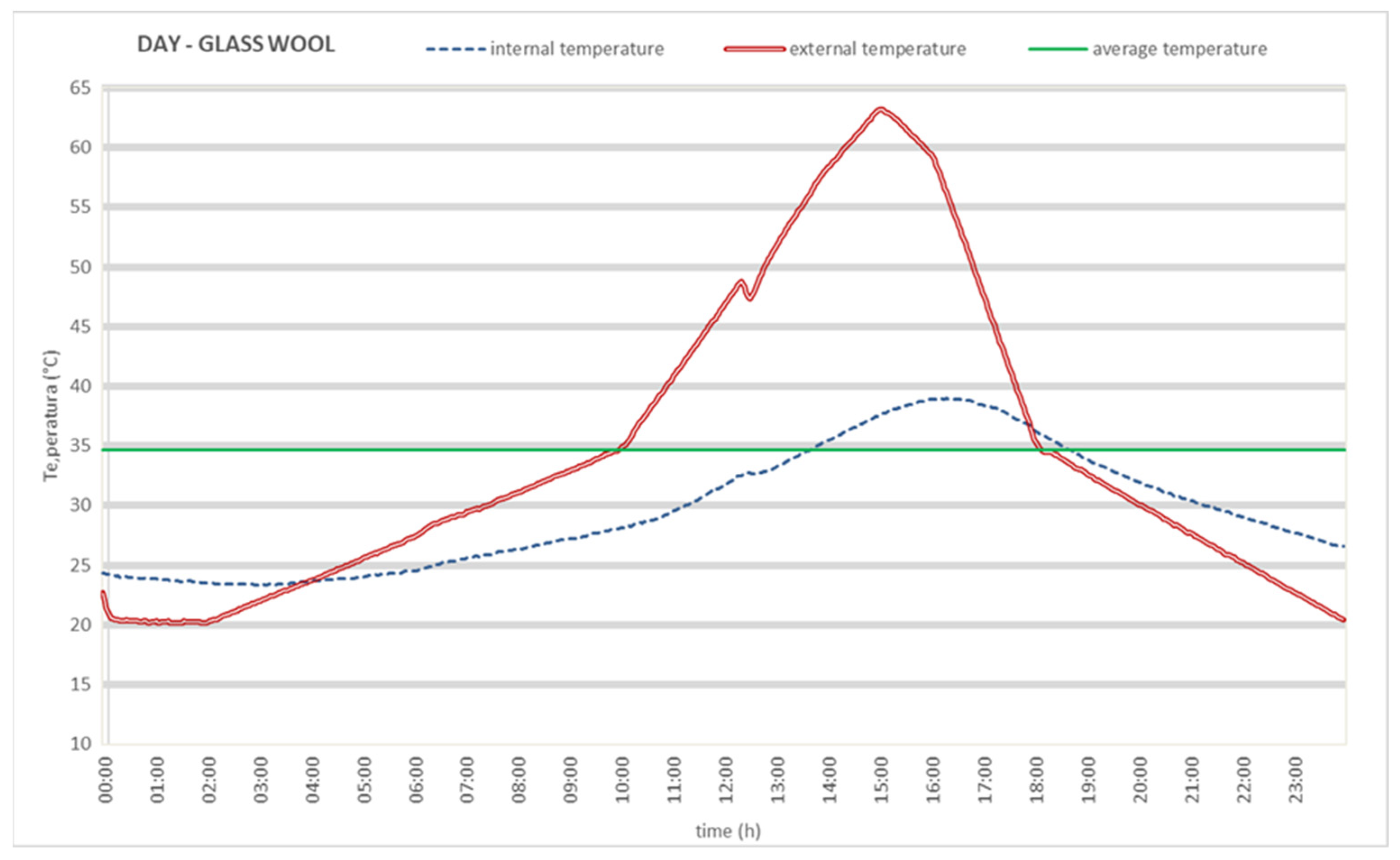
3.2. Time Shift and Decrement Factor

After evaluating thermal resistance, thermal conductivity, and thermal transmittance, a remaining issue is presented by the determination of the other two thermal performances needed to complete the characterization of the thermal insulating system. In order to assess them, according to some recent studies [29], it is possible to evaluate time shift and decrement factor by means of a sine wave reproducing the thermal curve of the outdoor surface temperature on the vertical envelopes at the peak year condition in Milan, basing on the average of ten years climate data (21 July, according to UNI code 10349 [38]).
Inside the climatic chamber, the daily thermal wave curve of the external surface temperature is reproduced.
With regard to previous studies [26,28], after the analysis of ten years weather data, the daily values of temperature and solar radiation in the city of Milan and data related to its use were collected. According to the data, the 21 July out door temperature variation in the context of Milan, for example, was simulated when it occurred on the hottest day of the year. The highest temperature reached by vertical envelopes with white paint during the life of a building, is around 65 °C [26]; as such, the peak temperature target during the reproduced thermal wave is 65 °C.
This procedure is possible because of the position of the sample, placed as the door of the climatic chamber. Thus, the sample divides the internal part of the chamber, which simulates the outdoor exposure, from the outside of the climatic chamber, which is the indoor of the building and then constitutes the indoor environment (Figure 3).
With a temperature sensor on the internal surface and on the external surface of the sample (Figure 4), the temperature peaks reached, and the time shift between them, are measured to evaluate these two important thermal parameters. Another air temperature sensor is placed in the laboratory room where the climatic chamber is located; it served for monitoring the air temperature of the laboratory, an air-conditioned environment with a recorded air temperature more or less stable throughout January–April at 20 ± 3 °C.
The first output of this approach is a temperature–time diagram corresponding to the thermal behavior of the ETICS during the hottest day of the year; it is used for determining decrement factor and time shift with Formulas (2) and (3):
Time   shift : Δ t = t T m a x , i n t t T m a x , e x t
D e c r e m e n t   f a c t o r :     f A = T m a x , e x t T m e d T m a x , i n t T m e d
T m a x , i n t = maximum internal (related to climatic chamber) surface temperature, corresponding with the external exposure in a real-building case;
T m a x , e x t = maximum external (related to climatic chamber) surface temperature, coinciding with the internal temperature in a real-building case;
T m e d = average external temperature during the hottest day of the year;
t T m a x , e x t = is the time when the maximum external temperature is reached;
t T m a x , i n t = is the time when the maximum internal temperature is reached.

3.3. Water Absorption

Water is considered to be the main cause of decay and, in fact, the most relevant ETICS performances are strictly related to water absorption [11,24]. This performance is determined by immersion of the specimens, with the skin submerged in a water bath according to the method described in Section 2.2.3 of EAD 040083 and according to UNI EN code 1609 [39]. Each specimen (with different thermal insulating materials) is immersed with the rendering facing downwards, to a depth of 10 mm for 3 min, and then for 1 h.
An additional water absorption test is carried out on supplementary 20 × 20 cm specimens, coated on the surface and not on lateral sides, where waterproofing is applied for the correct water absorption measurement, according to the EN code 1609 [39]. Three specimens are realized for each different thermal insulating material, and they were immersed with the rendering face downwards to a depth of 10 mm, at first for 3 min, and then for 24 h. The registered measurements are the average between the three specimens for each typology of sample within different thermal insulating materials.
Before these water absorption tests, thermal insulating materials are characterized according to water absorption, performing the same experiments only on the insulating panels without the coating.

3.4. Tensile Strength Perpendicular to Faces

This performance is determined according to the UNI EN code 1607 [40]. It is useful to evaluate this performance because the detachment of adhesive, of thermal insulating material, of base coat with embedded reinforcing fiberglass mesh, and of finishing coat can be avoided. In fact, natural exposure can stress ETICSs in real-building cases by means of wind action and detachment anomalies can occur in the stratigraphy of ETICSs.
Five specimens, sized 50 × 50 mm, are obtained by using a cutter on each ETICS sample; then, specimens were glued between two rigid plates in a machinery for a tensile strength test, pulling them in two opposite directions and measuring the maximum tensile strength.

3.5. Compressive Strength

Compressive strength is determined according to UNI EN code 826 [41]. Five square test specimens, sized 100 × 100 mm, obtained from each ETICS sample, are submitted to an applied compressive force in an axial direction. The forces, corresponding to 2% and 10% relative deformation, respectively, are reported. Figure 5 shows the test machine carring out a compressive strength test, whereas on the right the PC screen shows the output of the test, which consists of a stress–strain diagram.

3.6. Impact Resistance

Impact events can occur during ETICS service life for the components placed near the base of the building. Despite the lack of information about the occurrence, the frequency, and the intensity of impact events, it is possible to investigate impact resistance according to the standardized method of ISO code 7892 [42]. Two kinds of impact bodies are used in order to reproduce the effects of actual impacts on the ETICS sample. The principle consists of a rigid ball, weighing 0.5 kg, dropped from a height of 0.61 m, and a ball, weighing 1 kg, dropped from a height of 1.02 m.

3.7. Surface Degradation

According to the ISO code 4628 [30] it is possible to evaluate surface sample defects and changes through a normalized and unified standard, allowing the examination of the degree of blistering and cracking. By photographic detection of the degradation, ISO 4628, allows for the evaluation of surface decay through the designation of the quantity and size of defects, and of the intensity of uniform changes in appearance.

4. Results and Discussion

The experiment followed these phases:
(1)
Realization of ETICS samples by varying the insulating material among grey EPS, PU, GW, MW, ICB, and WF, without varying the other layers;
(2)
Collection of data related to an in-use ETICS with an adequate population, with the same stratigraphy as the sampled ETICS; characterization of the in-use ETICS solutions according to:
  • Stratigraphy;
  • Age of realization;
  • Performance degree (blistering grade through photographic degradation survey according to ISO code 4628-2);
(3)
Execution of accelerated ageing test on the samples in climatic chambers, measuring the state of decay after a fixed number of cycles;
(4)
Statistical correlation between performance decay on the samples and on the in-use solutions, and obtainment of the mean re-scaling factor;
(5)
Evaluation of the decay before the test, and after number of cycles that have been found out to correspond to n years. The decay is measured according to the seven aforementioned tests. The first results, listed in the paragraphs 4.1, 4.2, and 4.3, record thermal performances and the water absorption test. With regards to the last performances (the mechanical ones), they will be analyzed hereafter, since they are destructive tests and they are not repeatable;
(6)
Realization of the performance–time curve for each of the solutions represented by the six samples.

4.1. Thermal Resistance/Transmittance Assessment

The first measurement is concerned with the thermal transmittance according to the EN code 12667 [34], as described in Section 3.1. This allowed for the verification of the real thermal transmittance, which is different from the calculated one, and which derives from the value of thermal conductivity shown in Table 1.
Table 4 reports experimentally measured thermal transmittance and thermal resistance of all of the six studied ETICSs before accelerated ageing cycles.
For the sake of completion, a thermal resistance test was even carried out according to the EN code 12667 [36] on the whole stratigraphy, i.e., OSB, plasterboard, and finishing coat (total thickness = 30.32 mm) without the thermal insulating material, to determine the thermal transmittance and the thermal resistance, which are 3.78 W/m2K and 0.26 m2K/W, respectively.
Then, the measurements of thermal transmittance and the resistance of whole ETICSs after accelerated ageing tests have been partially carried out—they were completed only on two insulating materials—producing the results reported in Table 5.
These measurements show a very slight decrease in thermal performance during ageing and, in particular, polyurethane shows a percentage increase in conductivity by only 4%, which can be related to the range of tolerance of the measurement methodology, realized according to the EN code 12667.
A difference between the declared conductivity of the insulating panels and the measured one can be observed; the explanation can be found in EN code 13172 [43], as well as in the production of insulating materials, which introduce measurement tolerances as follows in Formula (4):
τ = k × s
τ = Tolerance specified in the product standard;
k = Factor related to the number of available test results;
s = Standard deviation.
This tolerance in the conductivity measurement produces a small difference from the mean value of conductivity. According to the code, the declared conductivity is calculated as follows in Formula (5):
λD = λM + τ
λD = Declared thermal conductivity of insulating panel;
λM = Measured thermal conductivity of insulating panel.
Then, according to the statistic tolerance interval of the code, K factor is a statistically reducing performance index, which reduces to 1% the probability of measuring conductivity values out of the statistical tolerance interval. As such, this residual possibility could explain the difference between the data from the producers and from the laboratory tests of this research.
Moreover, as it is known, in rigid expanded polyurethane foams thermal conductivity rises in the first years because of the diffusion in bounding parts on the panel of partof blowing agents (gases) contained in the closed-cell foam towards the outside [44], partially substituted by air. In order to assess this phenomenon, technical rules have been provided in the text to the standard of EN 13165—Annex C [45], two methods which can be used by manufacturers. During both procedures, the producer will have to add a statistical correction to the obtained value factor that ensures an adequate correspondence of the value to that of the declared performance after 25 years. The specific harmonized product standards (Annex A and C of the UNI EN 13165 for polyurethane products) provide the methodologies applied for the determination of the declared thermal conductivity value, λD, which is the average thermal conductivity value of the product for 25 years of service life. This is the reason why PU shows a thermal conductivity measured at time T0 and T1 lower than the declared thermal conductivity, as shown in other studies [46,47].
Our findings indicate that PU has a thermal conductivity lower than the one declared during service life, and the explanation is that this material has an initial variation regarded by the related code (UNI EN 13165), which determines the declared conductivity of the technical datasheet.
Some insulating materials seem to measure little differences with regard to the declared values and the measured ones.

4.2. Time Shift and Decrement Factor Assessment

Regarding the thermal performances of studied ETICS samples, the approach and the terminology for assessing dynamic behavior performances, described in Section 3.2, have been followed. The following figures show the sine wave reproducing the thermal curve of the outdoor surface temperature on vertical envelopes within MWs (Figure 6), GWs (Figure 7), and ICBs (Figure 8) at the peak year condition, the hottest day of the year.
Through these sine wave curves, it was possible to calculate the time shift and decrement factor based on Equations (2) and (3). Table 6 collects all recorded results in the first performance measurements, the time zero measurements determined before accelerated ageing tests.
Even though the purpose was to reach the same thermal resistance with all insulating materials by adopting different widths inversely proportional to thermal conductivity in order to evaluate thermal inertia on a homogeneous base, it was not possible to achieve the same values as the materials are only available in thicknesses corresponding to multiples of centimeters, resulting in differences between the values of thermal resistance between the samples. These are listed in Table 6 in a crescent order, according to which the materials are sorted.
As expected, it can be observed in Table 6 that the decrement factor and time shift are directly related to thermal resistance.
After all the accelerated ageing tests, no big surface changes were detected for any ETICS samples. Despite the small visual changes, other performances have big changes. For example, in the ETICS sample with glass wool, time shift was measured at time T1 (after accelerated ageing tests), recording 52 min corresponding to a time shift decrease of 25.71 % compared to the first measurement at time T0 (70 min). On the other hand, other materials, such as polyurethane, show very little decrease in performance for time shift. Table 7 shows the variation of time shift before and after the accelerated ageing test and the related decreasing percentage.
These constitute the first results concerning experimentations on decay measurement. Further evaluations, deriving from future performance measurements, are necessary because although visual observations seem to suggest no decay, this output already shows that there are variations for the performances of the component.
As expected, our results show that insulating panels with higher thermal resistance or higher density (cork and glass wool) have longer time shift then lighter materials like polyurethane. Instead of this known aspect, our findings extend performance analysis to service life; although other performances have no perceivable degradation, a decreasing time shift over time was observed.

4.3. Water Absorption Assessments

Another test carried out for evaluating ETICS performances is the water absorption test, which constitutes one of the most important tests.
In Table 8, water absorption results are reported, first tested only on the thermal insulating panels (Table 8) and then on the whole sample with coating on the horizontal surface and not on lateral sides (Table 9), as described in Section 2.4.
The averages of the measurements for each typology of sample with different thermal insulating materials show an increasing water absorption in tests carried out for 3 min and carried out for 24 h.
Since ETICSs with MW and WF show unexpectedly high off-trend values in water absorption measurements (Table 9), this could be explained by deducing that all materials covered on the sides by waterproofing hide partially unsealed micropores. In open-structure materials such as MW and WF, this influences water absorption tests.
However, as shown in Table 10, water absorption results tested on ETICSs, as described in Section 2.4, are reported at time T0 before the accelerating ageing test, and at time T1 after the accelerating ageing test.
This test already shows an increasing water absorption average after accelerated ageing, except for mineral wools, which keep the high value of water absorption constant.
Considering that water is the main cause of decay in ETICS behavior, this performance may indicate the vulnerability of materials to the decay caused by water intrusion. The presence of water may involve the risk of an increase of weight, causing a higher shear stress on adhesive and mechanical fixings, especially in the correspondence of joints and T joints.
Our findings suggest that materials like wools, such as wood fiberfill, mineral wool, and glass wool, may be more exposed to this typology of degradation during service life because of their higher water absorption, especially because of driving rain, which causes a worsening of thermal performance because water is a thermal conductor.

5. Conclusions and Further Developments

This research accounts for previous studies dealing with many different methods for evaluating ETICS performance decay in order to design a new, more complete one, and also to define an adequate strategy for building maintenance. This new experimental approach provides a relative comparison of the role played by the insulating material itself in determining the durability of an ETICS. Six ETICS samples have been realized by keeping the same stratigraphy while varying the insulating material among the most-used insulating materials for vertical envelopes of ETICS, i.e., EPS, polyurethane, glass wool, rock wool, cork, and wood fiber.
As in other studies [48], the choice of a relatively wide variety of insulating materials has allowed the investigation of the relation between different properties.
Limitations of the study can be observed in the choice of one manufacturer for each insulating material and in the limited number of studied samples per type of insulating material. Since the study deals with slowly ageing materials, for evaluating ETICS behavior over time, in reasonable time, two samples per type of insulation material were made, tested, and aged; then, in case of unconvincing results, tests were repeated on the additional sample. Further progress could be made on the reliability of results by using more samples and by considering different producers of insulating materials.
As expected, first performance measurements have shown that ETICS samples with higher thermal resistance and density get better time shift during the sine wave day cycle.
Moreover, ETICSs have shown an increase of water absorption after ageing, and, on the other hand, ETICSs made with insulating materials such as wools, wood fiberfill, mineral wool, and glass wool, show higher short-term water absorptions. This kind of test simulates driving rain and the rising levels of decay related to water presence in ETICSs, with its entity depending on short-term water absorption. In fact, higher water absorption during service life involves the risk that thermal performance could worsen as water is a thermal conductor, and the risk of causing higher shear stress on adhesive and mechanical fixings because of the weight increase of the ETICS.
Other outputs of the tests have shown a difference between the declared conductivity of the insulating panels and the measured one. The explanation can be found in EN code 13172 [43], as it allows a slight statistical tolerance for the determination of the value of declared conductivity according to the measurements; even if the probability is low, the difference between the values in the research and the declared ones could be explained in this way.
These initial experimental measurements indicate interesting results related to the evolution of thermal transmittance, as they show a small increase after the accelerated ageing cycles, and show no decay at all on visual inspection. Our findings suggest that, after natural ageing, the thermal performance of an ETICS is not subjected to significant variations during service life.
The absence of performance decay on the samples in this experimental research suggests that panels and ETICSs have a high intrinsic durability.
All the samples have been correctly packaged according to a specific code, UNI 11715, which defines the directives for the correct design and implementation of thermal insulation systems on the exterior of new and existing buildings, and according to the specific ETA certification.
Of course, real-building cases may show different results and higher decay due to the presence of possible criticalities and defects determined during realization, such as incorrect application of the reinforcing fiberglass mesh directly laid on the insulating panels (not embedded within the base coat), insufficient thickness of render, unsuitable mechanical fixings (unproperly placed, with a limited number of them, or with a low fixing-depth of anchorage), not-matched joints between the panels, and panels applied without being staggered/offset.
The adopted methodology includes the implementation of stressful and long accelerated ageing cycles, in order to estimate the intermediate performance values at different times during ETICS service life. The methodology outlined and used in this paper constitutes an essential step in the definition of the main parameters to consider, and of their evaluations.
In the future development of this research through accelerated aging tests in a climatic chamber, the performance decay of the other solutions will be measured at the beginning and after a fixed number of cycles for each of the lacking samples, by evaluating the aforementioned performances (thermal resistance, time shift, decrement factor, water absorption, tensile strength perpendicular to faces, compression behavior, impact resistance, and surface degradation). Accelerated aging tests are performed for each sample separately, as they are positioned as the door of the climatic chamber, to obtain a detailed characterization of thermal performance, which represents the most important property of tested ETICSs through a so-called “day-cycle” to evaluate time shift and decrement factors according to a previous study [29].
The performance–time curves will be realized in terms of cycles, as these aimed to compare the chosen solutions, as well as in natural time, by relating the measured state of decay of the accelerated aged samples with the naturally aged building with ETICS cladding, assessing the time rescaling with a real-time abscissa.
The main targets of the research will be:
  • A comparison between all the most common and best-performing materials used as thermal insulation components in vertical envelopes of ETICSs, especially in regard to their durability in order to predict and quantify service life, and correctly plan maintenance with the future objective of a life-cycle assessment;
  • An investigation on the influence of the thermal insulation panel in ETICSs, rather than on the external renders (other studies have focused on the variable durability of the renders);
  • An investigation on ETICS durability through service life estimation by mean statistic value of the re-scaling factor, by relating the measured state of decay of the accelerated aged samples to the naturally aged components of real-building cases;
  • It is crucial to point out that the aim of the research consists in accelerated ageing cycles resembling real-time building cases (as the objective is to predict service life in given conditions), and to assess performance decay—and its evolution—over time (ISO code 15686-7-based [49]).
Further developments could involve interesting implications in ETICS life-cycle assessment. The identification of the modalities for performance decay of ETICSs will allow us to predict dates and types of planned maintenance, thereby avoiding unexpected events. This principle involves interesting implications in environmental impact too, since an on-condition maintenance is to be considered positively in the context of an LCA analysis. In this sense, it will be necessary to outline performance–time curves for the different types of ETICSs, for the purpose of identifying appropriate scenarios for the most suitable maintenance strategy, within the scope of planned maintenance.

Author Contributions

Conceptualization, R.L. and M.N.; methodology, R.L.; formal analysis, R.L.; resources, R.L.; data curation, R.L.; writing—original draft preparation, R.L.; writing—review and editing, R.L. and M.N.; supervision, M.N. All authors have read and agreed to the published version of the manuscript.

Funding

This research received no external funding.

Institutional Review Board Statement

Not applicable.

Informed Consent Statement

Not applicable.

Data Availability Statement

MDPI Research Data Policies.

Conflicts of Interest

The authors declare no conflict of interest.

References

  1. Global Status Report for Buildings and Construction. Towards a Zero-Emission, Efficient and Resilient Buildings and Construction Sector. Available online: https://www.unenvironment.org/resources/publication/2019-global-status-report-buildings-and-construction-sector (accessed on 3 January 2021).
  2. World Green Building Council. New Report: The Building and Construction Sector Can Reach Net Zero Carbon Emissions by 2050. World GBC 2019. Available online: https://www.worldgbc.org/news-media/WorldGBC-embodied-carbon-report-published (accessed on 28 December 2020).
  3. European Commission. Energy Performance of Buildings Directive. 2020. Available online: https://ec.europa.eu/energy/topics/energy-efficiency/energy-efficient-buildings/energy-performance-buildings-directive_en#:~:text=Buildings%20are%20responsible%20for%20approximately,building%20stock%20is%20energy%20inefficient (accessed on 28 December 2020).
  4. Bartosz, M.; Marta, M. Influence of rendering type on the environmental characteristics of expanded polystyrene-based external thermal insulation composite system. Sustainability 2020, 10, 47. [Google Scholar]
  5. Building Performance Institute Europe. 97% of Buildings in the Eu Need to Be Upgraded. Available online: https://www.bpie.eu/wp-content/uploads/2017/12/State-of-the-building-stock-briefing_Dic6.pdf (accessed on 17 April 2021).
  6. Global Energy Assessment Writing Team. Global Energy Assessment: Toward Sustainable Future; Cambridge University Press: Cambridge, UK, 2012; pp. 649–760. [Google Scholar]
  7. Hens, H.; Carmeliet, J. Performance Prediction for Masonry Walls with EIFS Using Calculation Procedures and Laboratory Testing. J. Therm. Env. Bldg. Sci. 2002, 25, 2. [Google Scholar] [CrossRef]
  8. European Assessment External Thermal Composite System (EAE); About ETICS. Available online: https://www.ea-etics.eu/etics/about-etics/ (accessed on 28 December 2020).
  9. Sala, S.; Mathieux, F.; Pant, R. Life Cycle Assessment and Sustainability: Supporting Decision Making by Business and Policy. In Sustainability Assessment of Renewables-Based Products: Methods and Case Studies; Dewulf, J., De Meester, S., Alvarenga, R., Eds.; John Wiley & Sons, Ltd.: Hoboken, NJ, USA, 2016; Volume 13, pp. 201–214. [Google Scholar]
  10. ISO 15686-2Code; Building and Constructed Assets–Service Life Planning: Service Life Prediction Procedures. International Organization for Standardization (acronym ISO): Genève, Switzerland, 2001.
  11. Samuelson, I.; Jansson, A. Putsade Regelväggar. [ETICS on Framework Walls], SP Rapport 2009:16; SP Technical Research Institute of Sweden: Borås, Sweden, 2009. [Google Scholar]
  12. Lisø, K.R. Building Envelope Performance in Harsh Climates: Methods for Geographically Dependent Design. Ph.D. Thesis, Norwegian University of Science and Technology, Trondheim, Norway, 2006. [Google Scholar]
  13. Lisø, K.R.; Kvande, T.; Thue, J.V. Learning from Experience–An Analysis of Process Induced Building Defects in Norway. In Proceedings of the 3rd International Building Physics Conference, Montreal, QC, Canada, 27–31 August 2006. [Google Scholar]
  14. Kvande, T.; Bakken, N.; Bergheim, E.; Vincent, J. The Durability of ETICS with Rendering in Norway–Experimental and Field Investigations. Buildings 2018, 8, 93. [Google Scholar] [CrossRef] [Green Version]
  15. Amaro, B.; de Brito, J.; Flores-Colen, I. Statistical survey of the pathology, diagnosis and rehabilitation of ETICS in walls. J. Civ. Eng. Manag. 2012, 20, 511–526. [Google Scholar] [CrossRef] [Green Version]
  16. De Freitas, S.; Vasco, P. Cracks on ETICS along thermal insulation joints: Case study and a pathology catalogue. Struct. Surv. 2016, 34, 57–72. [Google Scholar] [CrossRef]
  17. Jelle, B.P. The Role of Accelerated Climate Ageing of Building Materials, Components and Structures in the Laboratory. In Proceedings of the 7th Nordic conference on Construction Economics and Organisation, Trondheim, Norway, 12–14 June 2013. [Google Scholar]
  18. Jelle, B.P. Accelerated climate ageing of building Materials, Components and Structures in the Laboratory. Mater. Sci. 2011, 47, 6475–6496. [Google Scholar] [CrossRef] [Green Version]
  19. Bochen, J. Durability assessment of durability materials exposed to atmosphere agents by testing in simulated environment. ACEE 2013, 6, 17–25. [Google Scholar]
  20. Bochen, J.; Gil, S.; Szwabowski, J. Influence of ageing process on porosity changes of the external plasters. Cem. Concr. Compos. 2005, 27, 769–775. [Google Scholar] [CrossRef]
  21. Bochen, J.; Gil, S. Study on the microstructure of thin-layer facade plasters of thermal insulating system during artificial weathering. Constr. Build. Mater. 2009, 23, 2559–2566. [Google Scholar] [CrossRef]
  22. Bochen, J. Properties of pore structure of thin-layer external plasters under ageing in simulated environment. Constr. Build. Mater. 2009, 23, 2958–2963. [Google Scholar] [CrossRef]
  23. Brandt, E. Building Materials and Components in Vertical Position: Exposure to Accelerated Climatic Strains; Nordest Espoo: Alborg, Finland, 2000. [Google Scholar]
  24. Norvaišienė, R.; Burlingis, A.; Stankevičius, V. Durability Tests on Painted Facade Rendering by Accelerated Ageing. Mater. Sci. 2010, 16, 80–85. [Google Scholar]
  25. Daniotti, B.; Iacono, P. Evaluating the Service Life of External Walls: A Comparison between Long-Term and Short-Term Exposure. In Proceedings of the 10th International Conference on Durability of Building Materials and Components, Lyon, France, 17–20 April 2005. [Google Scholar]
  26. Daniotti, B.; Spagnolo, S.L.; Paolini, R. Climatic Data Analysis to Define Accelerated Ageing for Reference Service Life Evaluation. In Proceedings of the 11th International Conference on Durability of Building Materials and Components, Istanbul, Turkey, 11–14 May 2008. [Google Scholar]
  27. Daniotti, B.; Lupica Spagnolo, S.; Paolini, R. Procedures for Reference Service Life Assessment of Building Components: Advances in research. In Proceedings of the International Conference on Construction & Building Research, Madrid, Spain, 14–26 June 2009. [Google Scholar]
  28. ETAG004; Guidelines for European Technical Approval of External Thermal Insulation Composite Systems (ETICS) with Rendering. European Organisation for Technical Approvals: Brussels, Belgium, 2014.
  29. Daniotti, B.; Paolini, R.; Re Cecconi, F. Effects of Ageing and Moisture on Thermal Performance of ETICS Cladding. In Durability of Building Materials and Components, 3rd ed.; Building Pathology and Rehabilitation; de Freitas, V.P., Delgado, J.M.P.Q., Eds.; Springer: Berlin, Germany, 2009; Volume 3, pp. 121–171. [Google Scholar]
  30. ISO 4628 Standard; Paints and Varnishes–Evaluation of Degradation of Coatings–Designation of Quantity and Size of Defects, and of Intensity of Uniform Changes in Appearance. International Organization for Standardization (acronym ISO): Genève, Switzerland, 2016.
  31. UNI/TR 11715 Code; Thermal Insulation Products for Buildings–Design and In-Situ Installation of External Thermal Insulation Composite Systems with Renders (ETICS). Italian National Unification Body (acronym UNI): Milan, Italy, 2018.
  32. EAD 040083; External Thermal Insulation Composite Systems (ETICS) with Renderings. European Organisation for Technical Approvals: Brussels, Belgium, 2019.
  33. Andrady, A.L.; Pandey, K.K.; Heikkilä, A.M. Interactive effects of solar UV radiation and climate change on material damage. Photochem. Photobiol. Sci. 2019, 18, 804–825. [Google Scholar] [CrossRef] [PubMed]
  34. European Regulation n° 305/2011: Construction Product Regulation; European parliament: Bruxelles, Belgium, 2011.
  35. EAD 040427 Code; Kits for External Thermal Insulation Composite System (ETICS) with Mortar as Thermal Insulation Product and Renderings or Discontinuous Cladding as Exterior Skin. European Organization for Technical Approvals: Brussels, Belgium, 2019.
  36. UNI EN 12667; Prestazione Termica dei Materiali e dei Prodotti per L’edilizia. Determinazione Della Resistenza Termica Con il Metodo della Piastra Calda con Anello di Guardia e con il Metodo del Termoflussimetro. Italian National Unification Body (acronym UNI): Milan, Italy, 2002.
  37. ISO 6946; Building Components and Building Elements–Thermal Resistance and Thermal Transmittance–Calculation Methods. International Organization for Standardization (acronym ISO): Genève, Switzerland, 2017.
  38. UNI 10349 Standard; Riscaldamento e Raffrescamento Degli Edifici–Dati Climatici. Italian National Unification Body (acronym UNI): Milan, Italy, 2016.
  39. EN 1609 Standard; Thermal Insulating Products for Building Applications–Determination of Dimensional Short Term Water Absorption by Partial Immersion. European Committee for Standardization (CEN): Bruxelles, Belgium, 2013.
  40. EN 1607 Standard; Thermal Insulating Products for Building Applications–Determination of Tensile Strength Perpendicular to Faces. European Committee for Standardization (CEN): Bruxelles, Belgium, 2013.
  41. EN 826 Standard; Thermal Insulating Products for Building Applications–Determination of Compression Behaviour. European Committee for Standardization (CEN): Bruxelles, Belgium, 2013.
  42. ISO 7892 Standard; Vertical Building Elements–Impact Resistance Tests–Impact Bodies and General Test Procedures. International Organization for Standardization (acronym ISO): Genève, Switzerland, 1988.
  43. EN 13172; Thermal Insulation Products. Evaluation of Conformity. European Committee for Standardization (CEN): Bruxelles, Belgium, 2012.
  44. Glicksman, L.R.; Stewart, J. The Measurement of the Morphology of Closed Cell Foams Which Control the Overall Thermal Conductivity. In Proceedings of the Third Conference Insulation Materials: Testing and Applications, Quebec City, QC, Canada, 15–17 May 1997. [Google Scholar]
  45. EN 13165; Thermal Insulation Products for Buildings, Factory Made Rigid Polyurethane Foam (PU) Products. Specification European Committee for Standardization (CEN): Bruxelles, Belgium, 2012.
  46. Albrecht, W. Change over Time in the thermal conductivity of ten-year-old PUR rigid foam boards with diffusion-open facings. Cell. Polym. 2004, 23, 161–172. [Google Scholar] [CrossRef]
  47. Stefani, A. Stabilità nel Tempo delle Prestazioni Isolanti; Poliuretano Luglio 2003; Associazione Nazionale Poliuretano Espanso rigido (ANPE): Vicenza, Italy, 2003; pp. 8–10. [Google Scholar]
  48. Nicolella, M.; Landolfi, R.; Pino, A.; Scognamillo, C. Comparative Evaluations of Sustainability, Durability and Resilience of External Envelopes for Environmentally Efficient Buildings. In Proceedings of the Sustainable Built Environment Conference (SBE19), Milan, Italy, 4–5 September 2019. [Google Scholar]
  49. ISO 15686-7 Code; Building and Constructed Assets–Service Life Planning: Performance Evaluation for Feedback of Service Life Data from Practice. International Organization for Standardization (acronym ISO): Genève, Switzerland, 2001.
Figure 1. (a) Designed sample with 3 different thermal insulating panels and a T joint where it is used to place a mechanical fixing; (b) glued insulation panels, cut, and turned (c); insulating panels bonded to the plasterboard panel of the sample; (d) the sample, with the addition of the first plaster base coat with embedded reinforcing fiberglass mesh; (e) the sample, with the addition of the second coat with embedded reinforcing fiberglass mesh; (f) the sample constructed and finished with the top coat.
Sustainability 14 00980 g001
Figure 2. (a) Thermal resistance measurement according to EN 12667; (b) thermal resistance measurement of the stratigraphy needed to determine thermal resistance of each single material.
Sustainability 14 00980 g002
Figure 3. Placement of the sample inside the climatic chamber: (a) sample outside the chamber, placed on a stand; (b) sample being placed as the door of the climatic chamber, before addition of temperature sensors.
Sustainability 14 00980 g003
Figure 4. Temperature sensor position on the ETICS surface.
Sustainability 14 00980 g004
Figure 5. Compression test according to EN code 826; the machine apparatus is on the left and the report curve is on the right.
Sustainability 14 00980 g005
Figure 6. Sine waves reproducing the external surface temperature on the ETICS (red line) with MW as thermal insulating material, the internal surface temperature on the ETICS (blue line), and the average external temperature (green line) on the hottest day of the year.
Sustainability 14 00980 g006
Figure 7. Sine waves reproducing: the external surface temperature on the ETICS (red line) with GW as the thermal insulating material, the internal surface temperature on the ETICS (blue line), and the average external temperature (green line) on the hottest day of the year.
Sustainability 14 00980 g007
Figure 8. Sine waves reproducing the external surface temperature on the ETICS (red line) with ICB as the thermal insulating material, the internal surface temperature on the ETICS (blue line), and the average external temperature (green line) on the hottest day of the year.
Sustainability 14 00980 g008
Table 1. Characteristics of different samples with 6 types of thermal insulating materials.
Insulating MaterialsCommercial ETICS
Name
Insulating PanelWhole ETICS
D
(mm)
λD
(W/mK)
Uc
(W/m2K)
Rc
(m2K/W)
PUTermok8 Slim500.0280.511.97
Grey EPSTermok8 Modulare Biostone600.0310.472.12
MWTermok8 Minerale LR600.0360.531.90
GWTermok8 Minerale LV600.0340.511.95
ICBTermok8 Minerale SU800.0400.462.18
WFTermok8 Wood800.0430.542.04
UC = calculated thermal transmittance of whole ETICS (W/m2K); RC = calculated thermal resistance of whole ETICS (m2K/W); λD = declared conductivity of thermal insulating panel (W/mK); d = thickness of thermal insulating panel (mm).
Table 2. Characteristics of ETICS materials.
Materialsρm(kg/m3)Cpm(J/kg°K)μdWSd(kg/m2)
PU 34.03146456<0.2
EPS10.35134030–70≤0.5
MW89.0110301≤1
GW71.6610301≤1
ICB97.412100not declarednot declared
WF144.08225031
Base coat1550 ± 50 5–20Classe W2
(C ≤ 0.2 kg/m2min0.5) 3
Finishing coat1800 ± 100 Classe V2 media 2Classe W2 media 4
ρ = measured density for insulating materials, declared density for coats by technical datasheet; Cpd = specific heat capacity declared by technical datasheet according to UNI EN ISO 10456; μd = water vapor transmission property according to the EN code 12086 declared by technical datasheet; WSd = short-term water absorption according to EN 1609 declared by technical datasheet except from the last two materials; 2 finishing coat water vapor permeability measured according to UNI 1062; 3 the finishing coat water absorption is measured according to UNI 1062; 4 the base coat water measurement reports water permeability according to the UNI 1015-18.
Table 3. Designed accelerated ageing cycles; the main parameters are: number of cycles, machine/phase, time interval, temperature range, and relative humidity range.
Cycle TipologyCycle NumberPhase/
Insertion in:
Phase Dt (h) Cycle Dt (h) T (°C)RH
(%)
Heat–Rain80Heater3 8050
Spry1 15 ± 5 100
Drainage2615 ± 5100–50
Heat–Cold7Climatic Chamber8 7030
Climatic Chamber1624−100
Freeze–Thaw15Water bath8 15 ± 5100
Freezer14 −200
Stove2245050
Table 4. Characteristics of different samples with six types of thermal insulating materials before accelerated ageing cycles.
Insulating
Materials
Insulating PanelWhole ETICS
d
(mm)
λD
(W/mK)
λM
(W/mK)
UC
(W/m2K)
RC
(m2K/W)
UM
(W/m2K)
RM
(m2K/W)
PU 500.0280.0250.511.970.442.29
EPS600.0310.0340.472.120.492.03
MW600.0360.0420.531.900.591.70
GW600.0340.0380.511.950.541.86
ICB800.0400.0430.462.180.472.11
WF800.0430.0450.542.040.492.05
Calculated values are determined according to the declared conductivity of materials. Measured valued are determined according to the EN 12667 test, before accelerated ageing. S = insulating panel thickness (mm); λD = declared thermal conductivity of insulating panel; λM = measured thermal conductivity of insulating panel; UC = calculated thermal transmittance of whole ETICS; RC = calculated thermal resistance of whole ETICS; UM = measured thermal transmittance of whole ETICS; RM = measured thermal resistance of whole ETICS.
Table 5. Characteristics of samples with different types of thermal insulating materials, calculated then measured before accelerated ageing cycles, and then measured after accelerated ageing cycles.
Thermal CharacteristicsWhole ETICS within Following Insulating MaterialsMeasurement Unit
PolyurethaneEPS
λD0.0280.031W/mK
UC0.510.47W/m2K
RC1.972.12m2K/W
λ00.0250.034W/mK
U00.440.49W/m2K
R02.282.02m2K/W
λ10.0260.034W/mK
U10.460.50W/m2K
R12.182.02m2K/W
λD = declared thermal conductivity of insulating panel; UC = calculated thermal transmittance of whole ETICS; RC = calculated thermal resistance of whole ETICS; calculated values are determined according to the declared conductivity of materials; λ0 = thermal conductivity of insulating panel measured at time T0 before accelerated ageing; U0 = thermal transmittance of whole ETICS measured at time T0 before accelerated ageing; R0 = thermal resistance of whole ETICS measured at time T0 before accelerated ageing; λ1 = thermal conductivity of insulating panel measured at time T1 after accelerated ageing; U1 = thermal transmittance of whole ETICS measured at time T1 after accelerated ageing; R1 = thermal resistance of whole ETICS measured at time T1 after accelerated ageing; measured values are determined according to the EN 12667 test, before (T0) and after (T1) accelerated ageing.
Table 6. Measured performances of decrement factor and time shift at the time T zero, before accelerating ageing tests, with materials in a crescent order according to thermal resistance.
Materials/Characteristics:UM:GW ICBPU
Thermal ResistancemqK/W1.862.112.29
Decrement Factoradimensional0.15290.09270.0381
Time Shiftmin709862
Table 7. Measured performances of time shift at the time T0, before accelerating ageing test, and at time T1, after accelerated ageing tests for ETICS within GW, ICB, and PU respectively.
Time Shift/Materials:T0
before Accelerating Ageing Test
T1
after Accelerating Ageing Test
Decreasing Percentage
GW70 min52 min25.71%
ICB98 min70 min28.57%
PU62 min60 min3.23%
Table 8. Water absorption measurement of average between the three specimens for each insulating material typology expressed in kg/mq, measured after immersion for 3 min and for 24 h.
Thermal Insulating
Panels:
Mass 3 min
Kg/m2
Mass 24 h
Kg/m2
PU1.131.86
EPS2.982.98
GW1.374.33
MW3.367.17
WF1.927.40
ICB2.467.49
Table 9. Water absorption measurement of average between the three ETICS specimens for each insulating material typology expressed in kg/mq, measured after immersion for 1 h and for 24 h.
ETICS within Following Insulating Materials:Mass 1 h
Kg/m2
Mass 24 h
Kg/m2
PU0.171.15
EPS0.181.05
GW0.351.48
MW2.192.88
WF0.483.12
ICB0.301.43
Table 10. Water absorption measurement of ETICS specimens for each insulating material typology expressed in kg/mq, measured after immersion for 1 h at the time T0 before accelerating ageing test, and at time T1 after accelerated ageing test.
ETICS within Following Insulating Materials:T0
Kg/m2
T1
Kg/m2
PU0.170.35
EPS0.180.35
GW0.350.34
MW2.192.06
WF0.480.61
ICB0.300.40
Publisher’s Note: MDPI stays neutral with regard to jurisdictional claims in published maps and institutional affiliations.

