Abstract
Nowadays, electric vehicles attract significant attention because of the increasingly stringent exhaust emission policies all over the world. Moreover, with the fast expansion of the sustainable economy, the demand for electric vehicles is expanding. In the recent age, maintenance has seriously hampered the marketing and use of electric automobiles. As a result, the technique for maintaining electric vehicles is regarded as vital since it directly affects the security and availability for the end user and the passengers. Another key aspect of electric mobility is the integration of artificial intelligence in control, diagnostics, and prognostics. Meanwhile, a lot of research efforts are still devoted to developing and innovating electric traction systems, especially for diagnostic and prognostic purposes. Furthermore, topics covering important, current, and sustainability challenges should contain more than theoretical knowledge in high-quality education, particularly in engineering education. The purpose is to bridge the gap between the new technology and the learner’s circumstances through giving practical technical expertise and training in the sphere of overall engineering competences, to avoid non-standard, unskilled maintenance work. This article presents the first phase towards designing and developing a test bench of an electric vehicle’s powertrain used for research, learning and e-learning purposes, employing model-based systems engineering (MBSE) and systems modeling language (SysML) through the CESAM architecting and modeling framework. The aforementioned approach is used on our case study to build and present an operational viewpoint layout of the control, energy management, diagnostic, and prognostic test bench as part of the system’s initial phase of designing the system; the test bench layout proposed in this paper represents a flexible, low-cost, multidisciplinary downsized laboratory providing basic experiments related to e-mobility and covering numerous branches and study fields.
1. Introduction
During the last two decades, energy scarcity and environmental degradation have emerged as two of the most serious global challenges, given that the transportation industry is one of the leading contributors to greenhouse gas (GHG) emissions [1]. Conventional internal combustion engines (ICE) generate carbon dioxide, nitrogen oxides, carbon monoxide, and hydrocarbons, which contribute to global warming and have a negative impact on living creature health [2].
Based on recent statistical data, transportation sectors consume two-thirds of all oil [3], which is severely detrimental to human society’s long-term growth [4,5]. In a comparison of carbon dioxide emissions sources in the United States in 2019, Figure 1 illustrates that transportation contributes for more than a quarter of total emissions of carbon dioxide [6]. Driven by the Paris Climate Agreement’s global emission-reduction targets, the concept of electric vehicles (EVs) appears to be considered a more contemporary, sustainable, and futuristic response to these rising concerns; EVs has already grabbed numerous car producers, with several nations committing huge skills and material resources in this field [7,8]. The automotive manufacturers in the European Union have planned to restrict gasoline vehicle purchases, and on the other hand, the government of China has issued a plan for the electric vehicle industry development in the period of (2021–2035), outlining the targets for the next 16 years. According to the China Association of Automobile Manufacturers, China’s Electric vehicle production sales in 2020 were 1.366 and 1.367 million units, respectively (CAAM) [9,10].
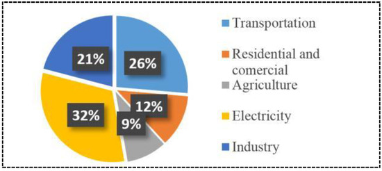
Figure 1.
Total U.S greenhouse gas emissions by sector (2019).
The reduction of harmful exhaust gases begins with Hybrid Electric Vehicles (HEVs), which are regarded as a transition phase to completely adopting electric vehicles, as after all they cause less pollution than conventional ICE vehicles. However, electric vehicles are currently less technologically developed than ICE vehicles, and further research in this area is required. ICE vehicles are less expensive than EVs and have a higher range rating and important power density, in addition to the longer charging time for EVs. Furthermore, as electric vehicles become an inescapable tendency, more concerns with the electric grid arise, such as degradation of the electric power-grid quality and the necessity to modernize existing electric power grids as a consequence of charging EVs on a massive scale—an actual problem that will require ongoing work in the long term [10].
Sustainable education development is defined as applying human, ethical, cultural, and environmental and social doctrines to higher education with the purpose of enabling societies with good practices that provide better growth and greater competitiveness of communities, institutions and organizations, thereby confirming awareness of and improving socio-economic life [11]. Quality education is a vital component of the development of mankind livability and the world’s long-term sustainability. Technology innovations are reshaping education in both official and unstructured contexts [12]. Foremost, the transition to an electric transportation system is generating significant attention, ranging from universities, research and development institutes, through automobile manufacturers and their suppliers. Training in this subject is becoming increasingly crucial for the future generation of specialists and engineers as transportation electrification project expenditures.
Training a younger generation of innovators in this field is crucial as spending on transportation electrification projects rises. Specialists in this discipline should be well-versed in a wide range of subjects of study, such as electric machines, vehicle dynamics, power electronics, power, energy storage, energy management systems [13,14], automotive engineering, software solutions, new intelligent and advanced control strategies, diagnostics and prognostics. However, simulations and tests of the hardware-in-the-loop (HIL) for electric vehicles and accurate vehicle tests also provide an interactive, intuitive, and participatory experience. Actually, because it is a high-tech, innovative and far-reaching product, the electric vehicle drive is often viewed as a complex system [15], and there is necessity to employ current design methodologies such as system engineering (SE) for such a system.
Systems engineering is a composite, multidisciplinary method for ensuring that intended systems are effectively designed, implemented, used, and retired [16]; it is quoted by ISO 12588, IEEE 1220 and EIA–632 [17]. Figure 2 highlights the spans of the standards that describe the processes independently of the system engineering implementation field.
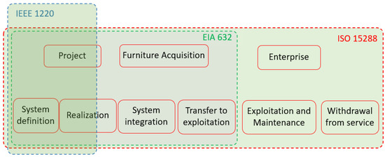
Figure 2.
The three ranges of system engineering standards.
Instead of document-based system engineering, both business and government have increasingly adopted model-based systems engineering (MBSE) as a approach to maintain track of system complexity concurrently with the rise of the digital-modelling environment [18], Systems Modeling Language (SysML) and Unified Modeling Language (UML), general-purpose languages, are used to implement MBSE. The most widely used MBSE approaches in the literature include Center of Excellence on Systems Architecture, Management, Economy and Strategy (CESAMES) Systems Architecting Method, IBM Harmony, U.S. Department of Defense Architecture Framework (DODAF) and MBSE Grid as a simplified SysML-based methodology [19,20]. These approaches provide a framework for organizing, classifying, and arranging architectural designs.
This endeavor is considered as a first stage toward the goal of an initiative to design and build an adaptable test bench of a powertrain for electric vehicles, aimed at educational and research purposes. The studied system of interest (SOI) is considered as a subsystem in the electric vehicle’s complex system that interacts with other EV’s subsystems. The study gives an operational analysis of our system, utilizing CESAM as the core framework and an MBSE grid architecture, as well as SysML as the modeling language. The paper is organized as follows: in the Section 1, we provide the goals and motives for our study, and in the Section 2 we explain the major components, including the system engineering, MBSE method, and the basis for the architectural design framework included in this work. The Section 3 includes the operational study of the investigated system utilizing the previously mentioned MBSE framework and SysML modeling language. Finally, a discussion is established about the contributions and future works.
2. Design Approach, State of Art and Discussion
2.1. Definitions and Discussion
A system could be defined as a collection of separated items that interact and connect parts and groups according to a series of requirements. In the same context, the entire group is interacting with its surroundings to form a coherent whole [16].
A complicated system is one whose behavior is troublesome to model because of dependencies, competitions, connections, or other sorts of exchanges between its elements or between a particular system and its surroundings. Complex systems exhibit a variety of features as a result of such links, including extremely nonlinear behavior, development, arbitrary structure, tolerance, and interface processes. In many cases, it is preferable to depict a system as a network, with nodes representing the components and connections representing relationships. Model-based systems engineering (MBSE) is a structured approach for assisting with the requirements, planning, design, assessment, evaluation, and confirmation of complex systems. In contrast to document-centric engineering, MBSE prioritizes models at the center of system design [17]. In the context of digital modeling, MBSE is more advantageous than document-based systems engineering; in a digital-modeling environment, it offers benefits that document-based systems engineering does not. Numerous papers are generated in a document-based way by multiple writers to visualize the system’s design from various stakeholder viewpoints, such as system behavior, software, hardware, security, safety, or other perspectives. A digital modeling approach is used to provide a single source code for the system, with a representation that is specific to the disciplines of the generated system using the same components. On the other hand, due to the continuous digitalization of the business world and the need for quality data in order to make faster decisions in complex environments, the authors in [21] present a broad overview of the literature on enterprise digital-resource planning adoption and the key to its success.
A digital modeling environment also creates a consistent standards-based technique for documenting the system, and it can be programmatically checked to avoid model inconsistencies and guarantee that all stakeholders adhere to similar regulations. This collaborative modeling framework improves structural analysis and reduces the number of faults introduced by a traditional technique. The capacity to examine digitalized system information throughout subfields guarantees that changes, new information, and design decisions are delivered to all stakeholders consistently. When MBSE is correctly applied, total development risks are decreased [22].
MBSE is commonly associated with the following concepts: model, systems engineering, framework, process, systems thinking, and tool. A model is a simplified representation of anything, such as a graphical, physical, or mathematical approximation that abstracts reality to eliminate some of its complexity. A system must be represented with lesser possible information, so the purpose is that its behavior and structure could be viewed and its complexity could be handled. To put it differently, models must appropriately reflect the system, and the models must be validated by the system. Systems thinking is a method of perceiving a system as a component of a larger system rather than as a standalone element. It is not the same as adhering to excellent planning, collecting statistics, or being meticulous [23].
Systems engineering (SE) is an interdisciplinary discipline of engineering and engineering management that concentrates on how to manage, integrate, and design complex systems throughout their life cycles. System thinking is at the center of SE, and it is used to arrange the said set of insights and facilitate the objects working together in a harmonious way to conduct a constructive activity. However, when handling large or complex projects, problems such as requirements elicitation, consistency, logistic support, interprofessional workforce organization, validation, supportability, and other disciplines are far more difficult to solve. In such tasks, system engineering tackles work processes, optimization approaches, and risk management tools to bridge the gap between technical and human-centered disciplines.
A process is a logical sequence of actions carried out to achieve a certain purpose. The structure of a process allows for numerous levels of aggregation to meet diverse decision-making criteria. A method outlines “WHAT” should be done as opposed to “HOW” each job should be accomplished [17]. It consists of both management and technical processes to achieve that equilibrium and alleviate risks that can influence the accomplishment of the project. Management consists of diverse activities such as planning, supervising, and managing risks of the system technical baseline. Technical process, on the other hand, aims to analyze, design, and also test the system to guarantee the good interacting of the elements in order to achieve the main goal of the whole set.
Technical process consists of two main processes: first, specification and design process, which aims to define the requirements that will satisfy the stakeholders needs, and then assign the requirements to the elements of the system; second, test process, which consists of integrating the different items of the set to make sure that the whole system answers to the requirements needed [24].
Figure 3 shows a schematic perspective of the technical modeling process of systems engineering. It consists of three main processes [16]. The first two phases of the SOI are system boundary delineation and operational viewpoint, followed by a requirements analysis and a final needs analysis. Throughout this procedure, the SOI’s effectiveness measures are defined and determined [25]. We use these three key viewpoints in our study to be able to use the SysML modeling language, but we improve them based on behavioral considerations.
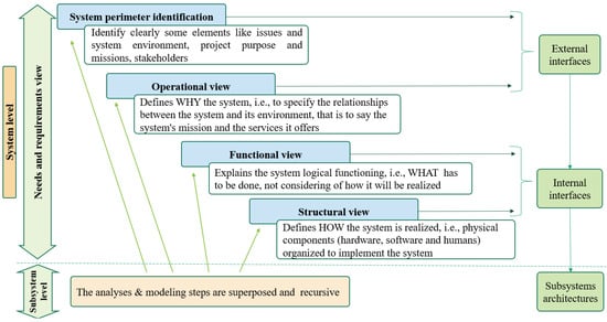
Figure 3.
Technical analysis and modeling process.
Process tasks are completed using approaches at all levels. Every technique is also a process in and of itself, with its own set of duties to perform. In other words, the “HOW” at one level of abstraction becomes the “WHAT” at a deeper level of abstraction. A tool is an object that, when used in conjunction with a certain method, may increase the efficiency of an activity, provided it is utilized appropriately and by someone who has the necessary skills and training. A tool’s purpose should be to make the “HOWs” easier to do. It enhances the “WHAT” and “HOW” in a broader sense. The most prevalent tools used to help systems engineering are computer- or software-based [26].
The usage of a framework is required to apply the MBSE method. A framework is a reference and a guideline for organizing all the components of a system’s design from several perspectives.
In this paper, we discuss the MBSE grid framework [27], and CESAM Systems Architecting methodology [20,26,28]. It is an architecture and modeling framework developed by CESAMES™, which meets the International Council on Systems Engineering (INCOSE) standards [29]. The overall system’s architecture can be defined using the following elements [24]:
2.1.1. A Tree Architectural Vision
The Figure 4 shows the generic relationships between the architectural visions as explained below.
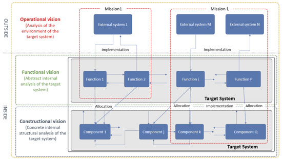
Figure 4.
Relationships between the three architectural visions.
- (a)
- Operational vision.
The operational perspective provides a black box depiction of a specific system; in this view the system of interest is represented by its exchanges and interfaces with its environment instead of by the system itself. The primary goal of this viewpoint is to comprehend the system’s necessity.
- (b)
- Functional vision.
This functional view provides a grey box concept of a specific SOI, in which one begins to apprehend the inside of the system, but mostly in aspects of input/output conceptual behaviour and attitude, in providing a more comprehensive understanding of what the system performs, without recognizing how it is straightforwardly structured and assembled at this juncture.
- (c)
- Constructional vision.
This viewpoint focuses on the system’s particular core pieces, including hardware, software, and humanware components, along with their interactions. Its major goal is to recover the physical architecture of the product. Consequently, it is frequently the most obvious component of the design of a system.
2.1.2. A Hierarchical Organization
The purpose of this illustration is to show how the number of elements and details increases as viewers go from one perspective to another. It is crucial to answer the research questions in the correct order, beginning with “Why?” and progressing to “What?” and “How?” In practice, it is critical to distinguish between “by order” and “successively” to avoid contradictory thinking. The Figure 5 shows the hierarchical organization presented as a pyramid.
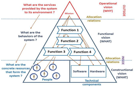
Figure 5.
The system architecture pyramid.
2.1.3. A global architecture matrix
The model’s global architecture can take the shape of a matrix known as the CESAM system architectural matrices, which comprises all the previously stated architectural elements; it preserves the model’s performance by creating a clear association of the various representations. Furthermore, the MBSE grid framework undermines the model’s depth and complexity, as well as the ambiguity of the links across levels of reasoning. This matrix is just a synthesis of the different architectural dimensions. It indeed presents all the types of views that allow us to exhaustively describe any system, classified according to:
- A first axis of classification corresponding to the three architectural visions; that is to say, the operational, functional and constructional visions.
- A second axis of classification corresponding to behaviors; that is to say, the conjunction of:
- o
- Expected properties;
- o
- All descriptions, states, static elements, dynamics and flows.
Crossing these two axes, one thus immediately acquires the matrix of Figure 6 where we listed the names of all different views that were introduced along the current section. As already stated above, the completeness of all these views in the matter of system specification is an immediate consequence of all the material that we introduced along the previous pages [17].
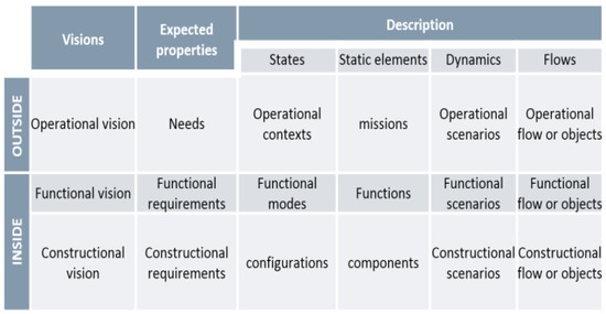
Figure 6.
The matrix of CESAM System Architecture.
2.2. State of Art
The internal combustion engines (ICE) industry has been saturated. In fact, it represents a mature field that reached its limited in the last decade, whether from a technological point of view, manufacturing, or even testing facilities. On the other hand, electric vehicles (EVs) nowadays are still a less mature technology and represent an active field of research to solve many difficulties and issues, whether in energy storage (batteries, fuel cells...) [30], autonomy, charging infrastructure, regenerative braking systems, or even the sudden rise in the electric power demand that would need a whole infrastructure [31]. It is true that green technology has known a great growing interest; however, nowadays we are in a situation where we are running out of time to launch the global mass production and marketing of different electric vehicles. Such a strategy would allow us to reduce the gaze’s emission and support the union governments to reach a more sustainable and greener (environment-friendly) vehicles industry. According to the European Union (EU) Agenda, only electric vehicles would be marketed in EU countries by the beginning of 2030.
In order to meet such a challenge, much research has been conducted concerning numerous issues encountered by EV technology. Authors in [32] highlight some of the challenges that the vehicle industry has to meet, and point out the difficulties that must be dealt with in order to make EVs meet the main stream for environmental sustainability. The upgrade of such a field requires the development of infrastructure, testing standards, validation centers, and certification agencies, in order to make EVs more inexpensive, dependable, and long-lasting. On the other hand, to develop such an industry, teaching scientific and technological advances along with professional training has to meet many complex challenges, in order to be more creative and innovant to solve current problems in the field. This training must meet some constraints such as connecting the academic sectors with the governmental, industrial, and social sectors.
In [33], a case study of a project developed with undergraduate engineering students is presented where the TEC21 model and Education 4.0 are integrated through new strategies and laboratories linked to industry, and the results of a multidisciplinary project focused on an electric vehicle racing team are presented. The project was a collaboration between academia and the productive sector. The results of such an indirect training showed the ability of students to acquire new and necessary skills and abilities that would allow them to be technological leaders in today’s modern industry. Such an experience allowed them to reach a suitable education framework by bringing together the characteristics established by Education 4.0.
Another project is presented in [34], whose goal is to establish an educational and academic LabVIEW-based simulator for HEV technology. The important capital investment and challenging and time-consuming tasks required to establish a full function of HEV laboratory represent enough evidence that the HEV industry requires a low-cost, computer-based virtual HEV simulator. An interactive LabVIEW-based simulation software was developed for various configurations of hybrid powertrains under several driving conditions. This software shows the ability to simulate, illustrate, and display the numerous energy flows in the HEV based on its configuration and driving conditions. It has also been merged with actuators and has been assembled in order to be used as a hands-on experience unit for multidisciplinary students, in order to make them more familiar with the HEV technology courses. Such an educational project and simulators not only provide a new approach in HEV training and education, but also increases students’ interest in the green changes movement, which has an objective of making the transportation field a more environment-friendly sector.
Authors in [35] also presented a work focusing on the implementation of a PHEV educational-demonstration unit along with its design steps and different issues to be considered during the conception. The unit can be used as a PHEV teaching tool for teachers and students, and in addition, it has been tested for different driving modes and showed good results. Afterwards, the unit was delivered to Macomb Community College in the summer of 2008. Nowadays, the unit represents a crucial part of the laboratory equipment aiming to offer and deliver various courses on hybrid electric vehicle technology. Authors focused on establishing a model-based design of a multi-functional hardware-in-the-loop (HiL) test bench for energetic investigations on electric vehicles with fuel cells as a means of range extension. The test bench is designed in a modular way so that only one test bench covers various test cases, such as parameter identification and validation of simulation models, as well as the verification and optimization of complex, cross-linked functions under real-time conditions. In the same context, a general model-based design method has been presented in order to design an electric car in [36]. The proposed technique has been used to optimize the vehicle’s energy consumption and consequently, increase the range, which is a critical functional parameter for currently developed electric vehicles. The main feature provided in this approach consists of combining optimization methods along with model-based design, creating additional possibilities of implementation of other different calculation methods used in the design of the vehicle, which would make it easier when it comes to selecting the most suitable method for a specific case.
Another related research paper [37] has focused this time on Lightweight Battery Electric Vehicles (LBEV) for educational purposes. The outcome was an EV characterized by many features, such as a completely open frame made of modular aluminum profiles, which offers full access to all parts of the vehicle and would also be convenient for future modifications. The frame is also spacious, which facilitates the integration of almost any powertrain unit, including the battery in both front and rear of the vehicle. In addition, the battery integration is flexible in a way that it can suit being either under the floor or in the center tunnel, along with guaranteeing safe use of the vehicle and protection against any electric shock according to the designers. On the other hand, authors in [38] lay out the design steps to develop a laboratory test bench with hardware-in-the-loop (HIL) capabilities, in order to emulate a Series Hybrid Electric Vehicle (SHEV). Authors also discussed the encountered challenges of developing a HiL test bench for SHEV emulation. As a result of the whole research study, an overall architecture and system component layout in addition to a real-time control algorithm for the test bench were proposed and validated by experimental implementation on a specific drive cycle. Another study focusing on energy management is presented in [39], where a strategy development process is proposed and applied in the case of hybrid electric vehicles (HEV) to demonstrate the model-based development methodology. The HEV energy management control strategy was developed with the model-based V-model development methodology, guaranteeing control precision and helping to reduce development time. Authors in [40] also proposed a battery electric vehicle (BEV) MBSE model called FReDy, which uses intelligent chassis systems. This research vehicle is equipped with two electric drives on the rear axle fixed next to the wheels. FReDy combines electric traction with an intelligent chassis consisting of four independent active wheel modules and is a fully active electric vehicle. Using a hierarchically structured vehicle management, FReDy offers the feature of driving in an optimized way regarding not only energy consumption but also driving dynamics safety. Another interesting work was realized by authors in [41], which describes the implementation of a flexible laboratory test bench for developing EVs and HEVs powertrains in a university environment. However, even if the test bench is implemented using relatively low-cost products, it is able to reach various and numerous objectives not even related to designs and tests of propulsion motor drives, but also HiL powertrain control strategies implementation. The paper illustrates the test bench capabilities by simulating the Jeep Commander II, a fuel cell Sport Utility Vehicle (SUV) from Daimler-Chrysler, performing the Urban Dynamometer Driving Schedule (UDDS) driving schedule, simulating the Prius, a commercially available gasoline-electric hybrid compact car from Toyota, performing the Japanese “10–15 mode” driving schedule, and determining the efficiency map of a three-phase Induction Motor (IM). Additionally, the test bench could be also used as a dynamic simulator for renewable energy sources such as wind turbine generators.
Many other researchers also used systems engineering to address many issues. An approach was presented in [16] where an operational analysis of EVs (which is considered as a complex system) following the model-based systems engineering approach was realized. Authors also lay out how such complex systems can significantly contribute to the European policies for sustainable development and give an overview of the architectural design framework they followed. Consequently, this approach allows us to identify key stakeholders, external interfaces, needs, use cases and operational scenarios. Other authors in [42] also presented a two-level approach which consists of two main components including MBSE. Here, MBSE is implemented using systems modeling language (SysML) to formulate different views and an architecture of the system of interest along with guaranteeing a real-time communication and collaboration of designs, which makes understanding change configurations, requirements verification, and traceability much easier. In a second level, a discrete-event simulation (Arena) tool is used as the reference simulation optimization tool for the model’s architectural analysis. Meanwhile, authors in [43] proposed a concept for model-based requirement engineering that aims to gather and offer requirements needed for different views within the automotive development process. The concept proposed consists of five partial models illustrating the emerging automotive system from an abstract point of view (use cases) to a concrete solution (system structure). Each of the partial models are described with respect to artifacts and their relations based on object-oriented modeling. These artifacts and relations play a major role in the assignment of different requirements or can be created by existing requirements. Such an approach provides a global view gathering all different sub-views of the EV and allows us to create structured and crucial documents, such as requirements specifications for each single system of the global complex system. At the same time, the impact of changes concerning any conception or design phase, or element, can be analyzed easily.
Another approach has been proposed in [44], where authors came up with the idea of switching the use of a domain-specific systems engineering approach from the energy domain to the automotive domain. Consequently, the outcome consists of establishing a new framework, a domain-specific language and a software toolbox, altogether enabling interdisciplinary modelling of electric vehicle architectures. Another concept was proposed in [45], where both a model-based design and testing method focusing on the EVs drivability aspect is proposed. The design approach is divided into two main steps. The first step consists of establishing a model-in-the-loop co-simulation in MATLAB/Simulink. The second step represents a mechanical-level hardware-in-the-loop test for a physical electric drive integrating the established EV model in MATLAB/Simulink in the real-time test case. This co-simulation approach has the advantage to provide a perfect combination between control engineering and system engineering in the simulation stage, but also when it comes to the HiL stage. The work [46] depicts a first version of a test bench, acquiring vibration, voltage, current, and speed in the presence of an eccentricity fault, and after test bench preparation, setup, settings, assembling and monitoring the data, and visualizing the results, the paper highlights the significance of gathering energy consumption data in the maintenance of squirrel cage induction motors..
In [47], authors extracted requirements for managing the complexity and interoperability of such systems. Furthermore, authors provided a comparative analysis of the state-of-the-art in existing architecture models and frameworks for e-mobility. Based on the identified gaps in existing research, authors came up with the E-Mobility Systems Architecture (EMSA) model, a three-dimensional systems architecture model for the e-mobility sector for which the structure is inspired by the well-known smart grid architecture model. Then, they further allocate all relevant entities from the e-mobility sector to the EMSA dimensions. Afterwards, a case study was established to validate and match the model qualitatively and quantitatively with various specific requirements. The evaluation outcome showed that the EMSA model succeeded to fulfill all system requirements, whether those related to complexity management or even those bounded to ensuring interoperability.
However, in the paper [48], a conceptual approach is presented on how to enable the integration of security by design in the development of smart grid systems. A major cornerstone of this approach is the development of a domain-specific and standards-based modelling language on the basis of the M/490 Smart Grid Architecture Model (SGAM). Furthermore, this modelling approach is utilized to develop a reference architecture model on the basis of the National Institute of Standards and Technology (NIST) Logical Reference Model (LRM) with its integrated security concepts. The availability of a standards-based reference architecture model enables the instantiation of particular solutions with a profound basis for security. Moreover, it is demonstrated how such architecture models can be utilized to gain insights into potential security implications and furthermore can serve as a basis for implementation.
On the other hand, other research such as [49] focused on the improvement and development of model-based software where two main challenges are to meet when it comes to development and verification in EVs. A first challenge consists of how to ensure model-level semantics preservation during implementation, which is crucial for software verification and certification. The second encountered challenge is related to reducing the computational and communication demand of distributed automotive control algorithms. For both these topics the authors provide a broad introduction to the problem followed by a discussion on state-of-art techniques.
The purpose of MBSE and its current level of maturity are discussed in the paper [50]. The authors give an example of how MBSE can be used for design synthesis to highlight a key MBSE feature. According to the authors, compared to current systems engineering techniques, MBSE has a number of potential advantages and benefits; among them are the following: transparency, traceable design, facilities for insistently storing both standard and custom models in the MBSE repository, creation of discipline-specific views for various engineering specialties, such as mechanical engineering and electrical engineering, automated model configuration management, gives support for various methodologies and life cycle models, provides multiple methods for requirements characterization, such as models, graphics, and prose and necessary semantics. In the end, MBSE has the ability to lower costs, attain greater quality, and shorten time to market. It might be indicated that authors in the research [51] evaluate the degree to which the advantages and worth of MBSE are supported by empirical data. The results of a comprehensive review show that only two studies offered measured evidence, whereas two-thirds of stated MBSE benefits are only supported by perceived evidence. The overall analysis in this research shows that expectations are the major foundation for statements regarding the worth and advantages of MBSE. The authors contend that the evidence for the worth and advantages of MBSE is still ambiguous.
The article [52] outlines a broad perspective and justification for MBSE’s adoption of digital twin technology. The authors present particular examples of the application and advantages of digital twin technology in various industries and explain the advantages of integrating digital twins with system simulation and the Internet of Things (IoT) in support of MBSE. A suggestion is made at the end to include digital twin technology in the MBSE approach and experimenting testbeds.
Finally, in a similar work, the authors in [53] attempt to construct an educational test bench setup for smart grids and renewable energy with numerous features and approaches utilized in a microgrid. The test bench is intended for students, laboratory engineers, and researchers, and it allows electrical microgrid system analysis and testing of new, advanced control algorithms to enhance energy efficiency. The goal of the endeavor is to create hybrid energy sources that integrate various electrical loads. The user may see the state of the components in each emulated scenario by utilizing open-source software that interfaces and communicates with the Open Platform Communications OPC Unified Architecture protocol. The work is constructed following a model-based engineering approach, which outlines the many needs and case studies of the intended test bench while respecting open-source software and frugal innovation aspects such as the usage of low-cost hardware and open-source software, the possibility for the users to add additional sources and loads, change software platforms, and interface with other simulators and equipment, which offers a personalized learning experience.
The model-based system engineering approach adopted in this work for the design of the studied system serves as a codified technique to assist the requirements, design, analysis, verification, and validation by utilizing a shared digital modeling environment across disciplines. Since the designed test bench is provided among the best practices in education regarding sustainable measures and approaches, considering its modularity, which is seen as an innovative perspective to include the most contemporary learning approaches and the evolutive technological aspects of the electric vehicle, the integration of the aforementioned methodology enables us to span the full system’s lifecycle and provide it as a subject for learning and e-learning purposes since it is developed in the organization and about an educational system. In other words, the design and the methodology are both seen as supports and subjects for educational purposes.
3. Motivation, Objectives, and General Approach
Due to its fundamental function of knowledge creation, teaching, and social innovation for sustainability, higher education is a primary agent for meeting the sustainable development goals outlined by the 2030 agenda. To accomplish this, higher education must incorporate longitudinally the concepts of sustainability in the development of the area of management, along with research, continued education, and obviously, instruction.
The specific goals of the proposed versatile educational test bench are to offer a personalized experience when it comes to learning about the electric vehicle aspects and improve the attraction to this field, in addition to providing creative approaches for automotive technical education as well as to complement theoretical and conceptual learning, stimulate and reveal academics’, developers’, and students’ attention on the process of designing such a versatile complex system for intelligent control, diagnostic, prognostic, and energy management of electric vehicles. It should be noted that many advances on the topic of electric vehicle diagnostics are already archived in [54,55], where we characterized the most used electric motor for the electric vehicle and established a data-driven diagnostic approach based on the measured electrical signal from the electric motor.
Among the project’s outcomes is the creation of new training materials of higher quality that focus on the most recent developments in vehicle technology. In terms of technology, the project exposes engineering students to contemporary EV components, such as traction machines, power converters [56], sensors, control units, super capacities, high voltage batteries [57], and communication networks [18]. Besides, the project focuses on the design tools for new control strategies, diagnostic and prognostic approaches, and energy management strategies.
The projected objectives this work aims to achieve are as follows:
- Formulating the requirements analysis and providing traceability.
- Framing different views of the model in line with SysML syntax.
- Providing real-time collaboration and communication of the model’s characteristics via the MBSE framework.
- Analyzing the different model architecture with Arena (via optimization).
- Performing a statistical analysis on the optimized architectures.
The test bench project targets are Bachelor’s and master’s degree candidates in electrical, electronic engineering, mechanical, researchers and PhD students. Figure 7 depicts a potential instructional strategy that includes three distinct learning levels.
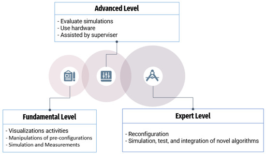
Figure 7.
The learning levels of the designed system.
3.1. Basic Level
Dedicated to beginners, this level includes a digital simulator of the real process, which includes the entire powertrain, ranging from the electrical motors to the energy storage devices, as well as the various electronic drives and vehicle dynamics simulations. By the means of a series of tests, exercises, interventions, and manipulations of the simulated system, the main goal of this learning stage is to present the existing state-of-the-art and the coeval technology for the control, diagnosis and prognostics and the energy management in the electric vehicle’s powertrain. Contemporary education features will be incorporated, which should aid in the removal of impediments, the provision of innovative and creative activities, and facilitation of knowledge and comprehension of such complicated procedures existing in current vehicles.
3.2. Advanced Level
This advanced level consists of manipulating and operating a physical and tangible laboratory workbench of an electric vehicle’s powertrain. It consists of an energy storage device, two primary inverters, and two electric motors, the first for simulating the vehicle’s inertia and motion resistances and the second as a traction machine through a switching portion. The goal behind including the switching component is to have two configurations in one electric traction powertrain by switching the role of each motor to test two different configurations. Students could manipulate and test the control techniques created and simulated in a preceding level using this pre-installed equipment, and the whole operation is achieved with the assistance of a supervisor.
3.3. Expert’s Level
The expert’s level is considered as the last one, where the user must have previously investigated the system very well and scrutinized the most recent artificial intelligence learning method, as well as the peculiarities of electric vehicle operation. The traction system may be modified, and new control systems created could be simulated, tested, and incorporated into interior stages. In this stage, PhD students and researchers are permitted to explore and test unprecedented solutions.
4. MBSE Based Design of the Versatile Test Bench
This work consists of combining the CESAM and MBSE grid frameworks to describe the concept and problems of the test bench, aiming to reflect the electric vehicle’s powertrain for educational purposes, including both physical learning and e-learning approaches, and designing and generating a model for this aim. The model of the examined system is constructed using the CAMEOTM system-modeler tool based on SysML language. Understanding and evaluating the demands of stakeholders, as well as specifying the system’s boundaries, seems to be the most important phase in the system development process. As a first phase, the goal of this study is to present the operational analysis of the SOI. It comprises gathering the necessary information to guarantee that the SOI’s goals are achievable. The essential steps of this process can be summarized as follows:
- Identifying and expressing the expectations of the stakeholders: The analysis of the inputs of the problem aims to identify useful and significant information (parameters, variables, and constraints) for modeling our system.
- Establishing the problem, finality, mission, system, objectives (PFMSO) diagram: The expression of these aspects is necessary to surround the system and provide any deviation of the initial objectives.
- Specifying requirements and the boundaries of the SOI with the various external participating stakeholders.
- Defining operational use scenarios: The use case definition is necessary to identify how the stockholders, the environment and the standards act on the system.
- Determining the SOI’s life cycle and interfaces with the different outside stakeholders: The determination of lifespan is crucial since it predicts the whole scenario of the product from design to withdrawal, and displaying its immediate surroundings and bounds defines the stakeholder’s responsibility for each phase of the lifecycle.
- Block diagram definition (BDD): Using SysML, the BDD of the studied system is decorticated, and the subsystem components are presented in an informative way.
4.1. Establishing a List of Stakeholders Demands
The engaged entities and individuals are susceptible to provide a source of requirements. Table 1 divides the different stakeholders and their needs into operational, performance, functional, and constraint subcategories, as well as other information resulting from market studies. Figure 8 illustrates the main needs diagram, which shows the stakeholders’ comprehensive expectations from the SOI. Hence, all aspects of the lifecycle, ranging from the stakeholders’ needs to the requirements diagram, have either traits in common or in extension.

Table 1.
Classification of the Stakeholders Needs.
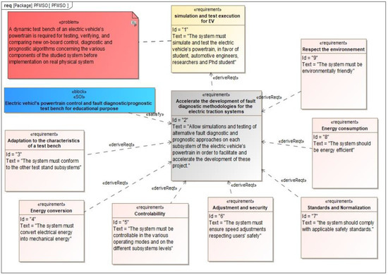
Figure 8.
The designed SOI’s PFMFSO diagram.
4.2. PFMSO Diagram of the Studied System
The diagram defining the Problematic, Finality, Mission, System, and Objectives (PFMSO) of the analyzed system is shown in Figure 8 and is utilized on purpose to frame the examined system. Using this frame, we specify a block to represent the system, as well as requirements to make clear the objective and the intent. The mission and the system are linked by a connection of satisfaction; rather, the purpose and the mission are connected by a link of association or derivation according to the modeling rules and the specifications of the system. If necessary, the mission can be enhanced by specifying sub-missions, allocating them identities, and linking them with a stereotype to elucidate.
4.3. Requirements of the Stakeholders
One of the key goals of this study is to evaluate the lifetime of the investigated system and then depict its immediate surrounds and boundaries. Figure 9 depicts the main and secondary requirements of the SOI. The requirements diagram shows the general expectations of the different internal and external stakeholders from the system of interest. The diagram includes the expectations. In general, the objective of requirement diagrams is to express both functional and non-functional requirements inside the model so that they may be tracked to other model parts that satisfy them and test cases that verify them.
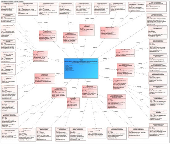
Figure 9.
Requirements diagram of the SOI.
4.4. Defining Operational Use Case
A use case is a single entity of meaningful work that provides a high-level picture of behavior that can be observed by someone or anything outside the system. The use case diagram is intended to describe and visualize use cases as well as the actors who extract value from the system. The use case diagram depicts the interaction between actors and use cases. While the use case diagram may look simple, it is a strong communication tool that communicates the value or goals that external roles attain by engaging with the system. Each use case may be described in depth, with descriptions, restrictions, and any number of scenarios including sets of steps executed alternately by the actor and the system to achieve the intended outcome. The operational use cases specify the services the system should allow the end user. This step may appear obvious, yet it aids in identifying stakeholders’ intents and, as a result, outlines demand much more clearly. Figure 10 depicts an example of a use case for the operating phase.
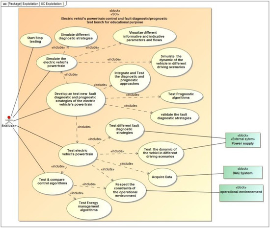
Figure 10.
Use case diagram of the SOI.
4.5. Life Cycle of the System of Interest
Model-based system engineering formalizes the use of systems engineering, involving the establishment and usage of a unified model that is compatible with numerous domain-specific representations of a product, and survives across the life cycle of a system. Figure 11 shows the life cycle of the electric powertrain test bench; it considers the exploitation and the maintenance as phase of the life cycle; the withdrawal phase defines the way of considering the end of the systems life including recycling. Table 2 displays the system’s lifetime stages, as well as the duties and ramifications of each stakeholder.
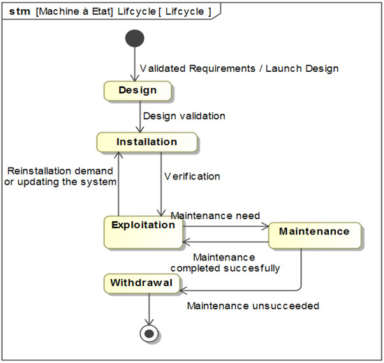
Figure 11.
Lifecycle diagram of the SOI.

Table 2.
Stackholder’s participation in the phases of the lifecycle.
4.6. Bloc Diagram Definition of the SOI
The aim of block definition diagrams is to describe system static structures that will be utilized for interface objects, control objects and data object. When used correctly, block diagrams are recursively scalable and able to be mathematically simulated. Figure 12 depicts the overall system architecture, including the various components, starting from the energy storage system to the electric traction machine and the electric motor for emulating load. A switching component is included in the proposed configuration, compared to the traditional electric powertrain, in an attempt to have two configurations of electric powertrains inside one arrangement, and the goal is increasing the number of control schemes to be evaluated.
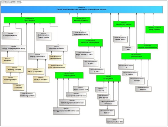
Figure 12.
Bloc diagram definition of the EV’s test bench.
5. Conclusions
When it comes to adopting sustainability in education, academic tools are an essential aspect of delivering higher education for sustainable development through teaching and learning processes and an adequate environment, and developing hands-on experiences for achieving tangible goals and objectives. When we examine and attempt the practices of teaching sustainability in distant electronic learning in the changes that the world has known in recent times, there are several concerns when compared to in-person teaching. Using the proposed design of the test bench, we provide a contribution that combines both concepts of learning and integrates various innovative technologies.
On the other hand, the design of a complex system, including a traction system for electric vehicles or a similar system, it is critical to study, inspect, analyze, manage, and regulate the elements, criteria, and factors, as well as dress and handle the variables that influence the system in any manner. Therefore, the incorporation of system engineering and the MBSE approach appears to be essential for providing adaptability, flexibility, and optimization across the whole process, particularly in research and development projects, in addition to serving as support for leaning and developing extended modules for the studied system.
With the aim of facilitating and improving the way that didactic strategies are presented and used, this paper is a preliminary stage towards the design and execution of an electric traction system’s fault diagnostic, prognostic, control and energy management test bench for educational purposes, and the deliverable achieved is indeed the development of an electric traction system’s test bench using model-based system engineering. When compared to existing educational laboratory equipment, this developed approach may be implemented at a very low cost and is simple to deploy in any institution or school. This design provides numerous sorts of case studies to students and researchers across multiple disciplines, especially electrical engineering, energy efficiency, advanced control, predictive maintenance, applied artificial intelligence, functional analysis, and mechanical engineering. Another most powerful point of our designed system is the use of the complex systems engineering approach for the conceptualization and the implementation, which is among the strongest approach used by the automotive manufacturers, justifying the learning purpose of this methodic approach.
Technical investigations must be conducted on additional pillars that correlate to each functional and constructional vision in future works to secure the entire design, execution, and implementation of the traction system. Our short-term goal is to widen the scope of the proposed system’s investigations by employing the aforementioned MBSE frameworks to give a functional analysis and then architectural vision. Our long-term perspectives are to expand the project to build a wireless remote monitoring and manipulating system, then develop a faraway problem diagnostic algorithm that relies on the system’s actual demands, as well as build a virtual reality environment and extend the project to other electric vehicle subsystems.
Author Contributions
Conceptualization, H.E.H.; Formal analysis, H.E.H.; Investigation, H.E.H. and N.G.; Methodology, H.E.H., N.G. and A.C.; Project administration, A.C.; Resources, F.-E.H. and O.L.; Software, H.E.H. and O.L.; Supervision, M.Z.; Validation, M.Z. and A.C.; Writing—original draft, H.E.H.; Writing—review & editing, A.C. All authors have read and agreed to the published version of the manuscript.
Funding
This research received no external funding.
Institutional Review Board Statement
Not applicable.
Informed Consent Statement
Not applicable.
Data Availability Statement
Not applicable.
Conflicts of Interest
The authors declare no conflict of interest.
References
- Kumar, R.R.; Alok, K. Adoption of Electric Vehicle: A Literature Review and Prospects for Sustainability. J. Clean. Prod. 2020, 253, 119911. [Google Scholar] [CrossRef]
- Li, Z.; Khajepour, A.; Song, J. A Comprehensive Review of the Key Technologies for Pure Electric Vehicles. Energy 2019, 182, 824–839. [Google Scholar]
- Zou, Y.; Wei, S.; Sun, F.; Hu, X.; Shiao, Y. Large-Scale Deployment of Electric Taxis in Beijing: A Real-World Analysis. Energy 2016, 100, 25–39. [Google Scholar]
- Krithika, V.; Subramani, C. A Comprehensive Review on Choice of Hybrid Vehicles and Power Converters, Control Strategies for Hybrid Electric Vehicles. Int. J. Energy Res. 2018, 42, 1789–1812. [Google Scholar] [CrossRef]
- Du, J.; Li, F.; Li, J.; Wu, X.; Song, Z.; Zou, Y.; Ouyang, M. Evaluating the Technological Evolution of Battery Electric Buses: China as a Case. Energy 2019, 176, 309–319. [Google Scholar]
- Sun, X.; Li, Z.; Wang, X.; Li, C. Technology Development of Electric Vehicles: A Review. Energies 2020, 13, 90. [Google Scholar] [CrossRef]
- Poullikkas, A. Sustainable Options for Electric Vehicle Technologies. Renew. Sustain. Energy Rev. 2015, 41, 1277–1287. [Google Scholar] [CrossRef]
- Kumar, L.; Jain, S. Electric Propulsion System for Electric Vehicular Technology: A Review. Renew. Sustain. Energy Rev. 2014, 29, 924–940. [Google Scholar] [CrossRef]
- William Cai, X.W.; William Cai, X.W. Review and Development of Electric Motor Systems and Electric Powertrains for New Energy Vehicles. Automot. Innov. 2021, 4, 3–22. [Google Scholar] [CrossRef]
- Khalid, M.R.; Alam, M.S.; Sarwar, A.; Jamil Asghar, M.S. A Comprehensive Review on Electric Vehicles Charging Infrastructures and Their Impacts on Power-Quality of the Utility Grid. eTransportation 2019, 1, 100006. [Google Scholar] [CrossRef]
- Klašnja-Milićević, A.; Ivanović, M. E-Learning Personalization Systems and Sustainable Education. Sustainability 2021, 13, 6713. [Google Scholar] [CrossRef]
- Tejedor, G.; Segalàs, J.; Barrón, Á.; Fernández-Morilla, M.; Fuertes, M.T.; Ruiz-Morales, J.; Gutiérrez, I.; García-González, E.; Aramburuzabala, P.; Hernández, À. Didactic Strategies to Promote Competencies in Sustainability. Sustainability 2019, 11, 2086. [Google Scholar] [CrossRef]
- El Maghraoui, A.; Ledmaoui, Y.; Laayati, O.; El Hadraoui, H.; Chebak, A. Smart Energy Management: A Comparative Study of Energy Consumption Forecasting Algorithms for an Experimental Open-Pit Mine. Energies 2022, 15, 4569. [Google Scholar] [CrossRef]
- Laayati, O.; El Hadraoui, H.; Bouzi, M.; Chebak, A. Smart Energy Management System: Oil Immersed Power Transformer Failure Prediction and Classification Techniques Based on DGA Data. In Proceedings of the 2022 2nd International Conference on Innovative Research in Applied Science, Engineering and Technology (IRASET), Meknes, Morocco, 3–4 March 2022; pp. 1–6. [Google Scholar]
- Reuter, B.; Gleyzes, D.; Lienkamp, M. Comparison of Life Cycle Greenhouse Gas Emissions of Conventional. In CNG-Hybrid and Electric Powertrains for Long Mileage Application in a Taxi for Singapore; SAE International: Warrendale, PA, USA, 2014. [Google Scholar]
- Doufene, A.; Dauron, A.; Chale, H.G.; Krob, D. 2.1.1 Model-Based Operational Analysis for Complex Systems—A Case Study for Electric Vehicles. INCOSE Int. Symp. 2014, 24, 122–138. [Google Scholar] [CrossRef]
- Krob, D. CESAM: CESAMES Systems Architecting Method a Pocket Guide; CESAMES Association: Paris, France, 2017. [Google Scholar]
- Madni, A.M.; Sievers, M. Model-Based Systems Engineering: Motivation, Current Status, and Needed Advances. In Proceedings of the Disciplinary Convergence in Systems Engineering Research, Redondo Beach, BC, Canada, 23–25 March 2017; Madni, A.M., Boehm, B., Ghanem, R.G., Erwin, D., Wheaton, M.J., Eds.; Springer International Publishing: Cham, Switzerland, 2018; pp. 311–325. [Google Scholar]
- El Hadraoui, H.; Ahmed, C.; Mourad, Z. Model-Based System Engineering Design of a Versatile Control Test Bench of an Electric Vehicle’s Powertrain for Educational Purpose. In Proceedings of the 2021 3rd Global Power, Energy and Communication Conference (GPECOM), Antalya, Turkey, 5–8 October 2021; pp. 233–239. [Google Scholar] [CrossRef]
- Douglass, B.P. Agile Systems Engineering. Available online: https://sciarium.com/file/211180/ (accessed on 28 May 2021).
- Vicedo, P.; Gil-Gómez, H.; Oltra-Badenes, R.; Guerola-Navarro, V. A Bibliometric Overview of How Critical Success Factors Influence on Enterprise Resource Planning Implementations. J. Intell. Fuzzy Syst. 2020, 38, 5475–5487. [Google Scholar] [CrossRef]
- Mazeika, D.; Morkevicius, A.; Aleksandraviciene, A. MBSE Driven Approach for Defining Problem Domain. In Proceedings of the 2016 11th System of Systems Engineering Conference (SoSE), Kongsberg, Norway, 12–16 June 2016; pp. 1–6. [Google Scholar]
- Cloutier, R.; Sauser, B.; Bone, M.; Taylor, A. Transitioning Systems Thinking to Model-Based Systems Engineering: Systemigrams to SysML Models. IEEE Trans. Syst. Man Cybern. Syst. 2015, 45, 662–674. [Google Scholar] [CrossRef]
- Guennouni, N.; Machkour, N.; Chebak, A. Using MBSE for Operational Analysis of Power Converter for Electric Traction. In Proceedings of the 2021 17th Conference on Electrical Machines, Drives and Power Systems (ELMA), Sofia, Bulgaria, 1–4 July 2021; pp. 1–6. [Google Scholar]
- Doufene, A.; Góngora, H.G.C.; Krob, D. Complex Systems Architecture Framework: Extension to Multi-Objective Optimization. In Proceedings of the CSDM, Paris, France, 12–14 December 2012; pp. 105–123. [Google Scholar]
- Estefan, J.A. Initiative Survey of Model-Based Systems Engineering (MBSE) Methodologies. Incose MBSE Focus Group 2008, 25, 1–12. [Google Scholar]
- Morkevicius, A.; Aleksandraviciene, A.; Mazeika, D.; Bisikirskiene, L.; Strolia, Z. MBSE Grid: A Simplified SysML-Based Approach for Modeling Complex Systems. INCOSE Int. Symp. 2017, 27, 136–150. [Google Scholar] [CrossRef]
- Leroux, R.; Pantel, M.; Ober, I.; Bruel, J.-M. Model-Based Systems Engineering for Systems Simulation. In Leveraging Applications of Formal Methods, Verification and Validation. Distributed Systems; Margaria, T., Steffen, B., Eds.; Springer International Publishing: Cham, Switzerland, 2018; pp. 429–448. [Google Scholar]
- Piques, J.-D. SysML for Embedded Automotive Systems: SysCARS Methodology. In Proceedings of the Embedded Real Time Software and Systems (ERTS2014), Toulouse, France, 5–7 February 2014. [Google Scholar]
- Laadissi, E.M.; Khalfi, J.; Belhora, F.; Ennawaoui, C.; Ballouti, A.E. Aging Study of a Lead-Acid Storage Bank in a Multi-Source Hybrid System. Indones. J. Electr. Eng. Computer Sci. 2020, 20, 1109–1117. [Google Scholar] [CrossRef]
- Berger, M.; Côté, O.; Chebak, A. Development of a DC-Link Protection System for Regenerative Braking of Electric Vehicle Using a Pseudo-Cascade Controlled IGBT Chopper. In Proceedings of the 2015 IEEE Transportation Electrification Conference and Expo (ITEC), Dearborn, MI, USA, 14–17 June 2015; pp. 1–7. [Google Scholar]
- Challenges of Electric Vehicles from Lab to Road. Available online: https://ieeexplore.ieee.org/document/8333880 (accessed on 18 April 2022).
- López, H.A.; Ponce, P.; Molina, A.; Ramírez-Montoya, M.S.; Lopez-Caudana, E. Design Framework Based on TEC21 Educational Model and Education 4.0 Implemented in a Capstone Project: A Case Study of an Electric Vehicle Suspension System. Sustainability 2021, 13, 5768. [Google Scholar] [CrossRef]
- Liao, G.; Yeh, C.-P.; Sawyer, J. Design and Implementation o f Virtual Hybrid Electric Vehicle Simulator for Educational Purpose. In Proceedings of the 2008 Annual Conference & Exposition, Pittsburgh, PA, USA, 22 June 2008; pp. 13.361.1–13.361.10. [Google Scholar]
- Xu, X.; Wang, C.; Liao, G.; Yeh, C.-P.; Stark, W. Development of a Plug-In Hybrid Electric Vehicle Educational Demonstration Unit. In Proceedings of the 41st North American Power Symposium, Starkville, MS, USA, 4–6 October 2009; pp. 1–7. [Google Scholar]
- Skarka, W. Model-Based Design and Optimization of Electric Vehicles. In Transdisciplinary Engineering Methods for Social Innovation of Industry 4.0; IOS Press: Amsterdam, The Netherlands, 2018; pp. 566–575. [Google Scholar] [CrossRef]
- Jandura, P.; Bukvic, M. Lightweight Battery Electric Vehicle for Educational Purposes. Appl. Mech. Mater. 2013, 390, 281–285. [Google Scholar] [CrossRef]
- Fajri, P.; Lotfi, N.; Ferdowsi, M. Development of a Series Hybrid Electric Vehicle Laboratory Test Bench with Hardware-in-the-Loop Capabilities. In Proceedings of the 2018 International Power Electronics Conference (IPEC-Niigata 2018-ECCE Asia), Niigata, Japan, 24 May 2018; pp. 3223–3228. [Google Scholar]
- Ao, G.; Qiang, J.; Chen, Z.; Yang, L. Model-Based Energy Management Strategy Development for Hybrid Electric Vehicles. In Proceedings of the 2008 IEEE International Symposium on Industrial Electronics, Cambridge, UK, 30 June–2 July 2008; pp. 1020–1024. [Google Scholar]
- Liu-Henke, X.; Scherler, S.; Fritsch, M.; Quantmeyer, F. Holistic Development of a Full-Active Electric Vehicle by Means of a Model-Based Systems Engineering. In Proceedings of the 2016 IEEE International Symposium on Systems Engineering (ISSE), Edinburgh, UK, 3–5 October 2016; pp. 1–7. [Google Scholar]
- Schupbach, R.M.; Balda, J.C. A Versatile Laboratory Test Bench for Developing Powertrains of Electric Vehicles. In Proceedings of the IEEE 56th Vehicular Technology Conference, Vancouver, BC, Canada, 24–28 September 2002; Volume 3, pp. 1666–1670. [Google Scholar]
- Ginigeme, O.; Fabregas, A. Model Based Systems Engineering High Level Design of a Sustainable Electric Vehicle Charging and Swapping Station Using Discrete Event Simulation. In Proceedings of the 2018 Annual IEEE International Systems Conference (SysCon), Vancouver, BC, Canada, 23–26 April 2018; pp. 1–6. [Google Scholar]
- Inkermann, D.; Huth, T.; Vietor, T.; Grewe, A.; Knieke, C.; Rausch, A. Model-Based Requirement Engineering to Support Development of Complex Systems. Procedia CIRP 2019, 84, 239–244. [Google Scholar] [CrossRef]
- Draxler, D.; Neureiter, C.; Lastro, G.; Schwartzkopff, T.; Boumans, M. A Domain Specific Systems Engineering Framework for Modelling Electric Vehicle Architectures. In Proceedings of the 2019 IEEE Transportation Electrification Conference and Expo, Asia-Pacific (ITEC Asia-Pacific), Seogwipo, Korea, 8–10 May 2019; pp. 1–6. [Google Scholar]
- Ciceo, S.; Mollet, Y.; Sarrazin, M.; Gyselinck, J.; Van der Auweraer, H.; Martiş, C. Model-Based Design and Testing for Electric Vehicle Driveability Analysis. In Proceedings of the 2016 IEEE 16th International Conference on Environment and Electrical Engineering (EEEIC), Florence, Italy, 7–10 June 2016; pp. 1–4. [Google Scholar]
- Laayati, O.; Bouzi, M.; Chebak, A. Smart Energy Management System: SCIM Diagnosis and Failure Classification and Prediction Using Energy Consumption Data. In Proceedings of the Digital Technologies and Applications, Fez, Morocco, 29–30 January 2021; Motahhir, S., Bossoufi, B., Eds.; Springer International Publishing: Cham, Switzerland, 2021; pp. 1377–1386. [Google Scholar]
- Kirpes, B.; Danner, P.; Basmadjian, R.; de Meer, H.; Becker, C. E-Mobility Systems Architecture: A Model-Based Framework for Managing Complexity and Interoperability. Energy Inf. 2019, 2, 15. [Google Scholar] [CrossRef]
- Neureiter, C.; Engel, D.; Uslar, M. Domain Specific and Model Based Systems Engineering in the Smart Grid as Prerequesite for Security by Design. Electronics 2016, 5, 24. [Google Scholar] [CrossRef]
- Goswami, D.; Lukasiewycz, M.; Kauer, M.; Steinhorst, S.; Masrur, A.; Chakraborty, S.; Ramesh, S. Model-Based Development and Verification of Control Software for Electric Vehicles. In Proceedings of the 2013 50th ACM/EDAC/IEEE Design Automation Conference (DAC), Austin, TX, USA, 29 May–7 June 2013; pp. 1–9. [Google Scholar]
- Madni, A.M.; Sievers, M. Model-Based Systems Engineering: Motivation, Current Status, and Research Opportunities. Syst. Eng. 2018, 21, 172–190. [Google Scholar] [CrossRef]
- Henderson, K.; Salado, A. Value and Benefits of Model-Based Systems Engineering (MBSE): Evidence from the Literature. Syst. Eng. 2021, 24, 51–66. [Google Scholar] [CrossRef]
- Madni, A.M.; Madni, C.C.; Lucero, S.D. Leveraging Digital Twin Technology in Model-Based Systems Engineering. Systems 2019, 7, 7. [Google Scholar] [CrossRef]
- Laayati, O.; El Hadraoui, H.; Guennoui, N.; Bouzi, M.; Chebak, A. Smart Energy Management System: Design of a Smart Grid Test Bench for Educational Purposes. Energies 2022, 15, 2702. [Google Scholar] [CrossRef]
- Hadraoui, H.E.; Laayati, O.; Guennouni, N.; Chebak, A.; Zegrari, M. A Data-Driven Model for Fault Diagnosis of Induction Motor for Electric Powertrain. In Proceedings of the 2022 IEEE 21st Mediterranean Electrotechnical Conference (MELECON), Palermo, Italy, 14–16 June 2022; pp. 336–341. [Google Scholar] [CrossRef]
- El Hadraoui, H.; Zegrari, M.; Chebak, A.; Laayati, O.; Guennouni, N. A Multi-Criteria Analysis and Trends of Electric Motors for Electric Vehicles. World Electr. Veh. J. 2022, 13, 65. [Google Scholar] [CrossRef]
- Guennouni, N.; Chebak, A.; Machkour, N. Optimal Dual Active Bridge DC-DC Converter Operation with Minimal Reactive Power for Battery Electric Vehicles Using Model Predictive Control. Electronics 2022, 11, 1621. [Google Scholar] [CrossRef]
- Elmarghichi, M.; Bouzi, M.; Ettalabi, N.; Derri, M. Comparison of State of Charge Estimation Algorithms for Lithium Battery. In Proceedings of the 2nd International Conference on Electronic Engineering and Renewable Energy Systems, Saidia, Morocco, 13–15 April 2020; Hajji, B., Mellit, A., Marco Tina, G., Rabhi, A., Launay, J., Naimi, S.E., Eds.; Springer: Singapore, 2021; pp. 293–300. [Google Scholar]
Publisher’s Note: MDPI stays neutral with regard to jurisdictional claims in published maps and institutional affiliations. |
© 2022 by the authors. Licensee MDPI, Basel, Switzerland. This article is an open access article distributed under the terms and conditions of the Creative Commons Attribution (CC BY) license (https://creativecommons.org/licenses/by/4.0/).