Mathematical Modeling of Efficiency Evaluation of Double-Pass Parallel Flow Solar Air Heater
Abstract
:1. Introduction
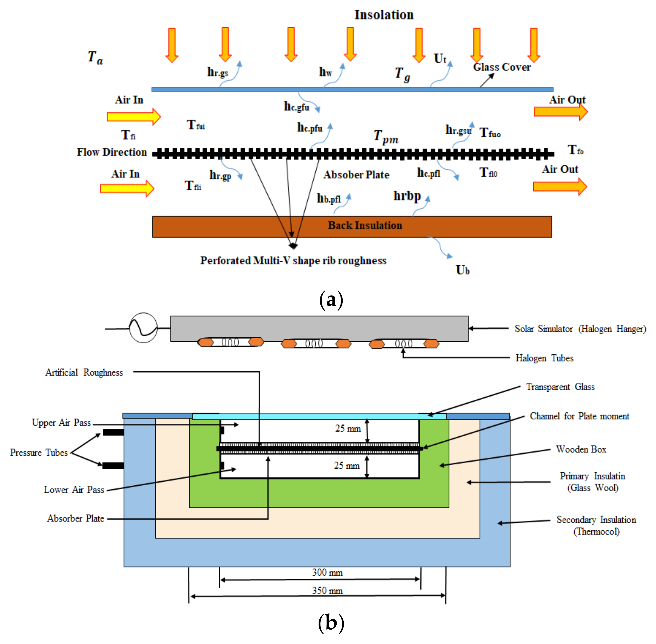
2. Experimental Setup and Model for DPPFSAH
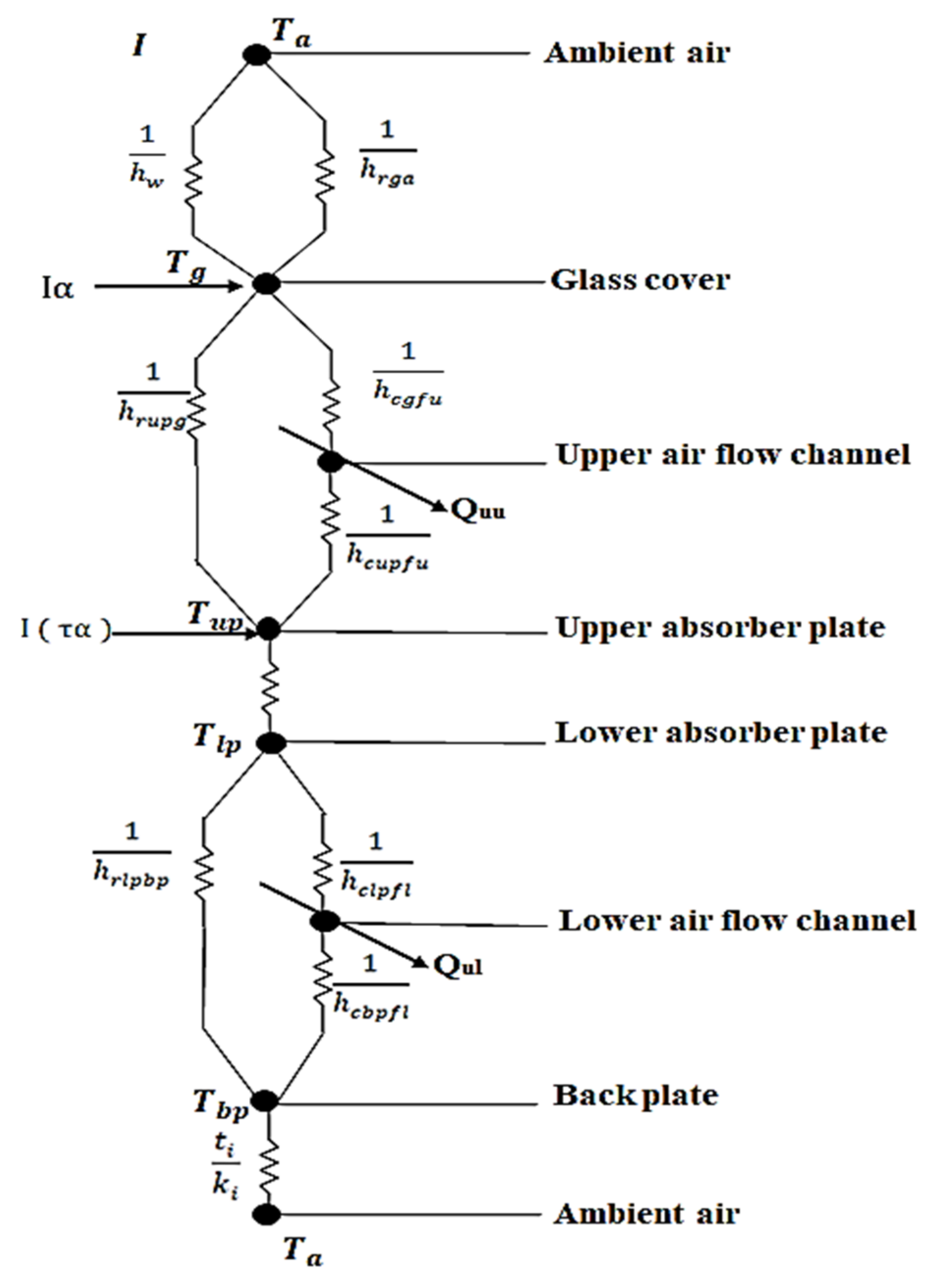
Heat Transfer Modes and Assumptions for Boundary Condition
3. Thermo-Hydraulic Performance of DPPFSAH
4. System and Operational Parameters
4.1. Fixed Parameters
4.2. Variable Parameters
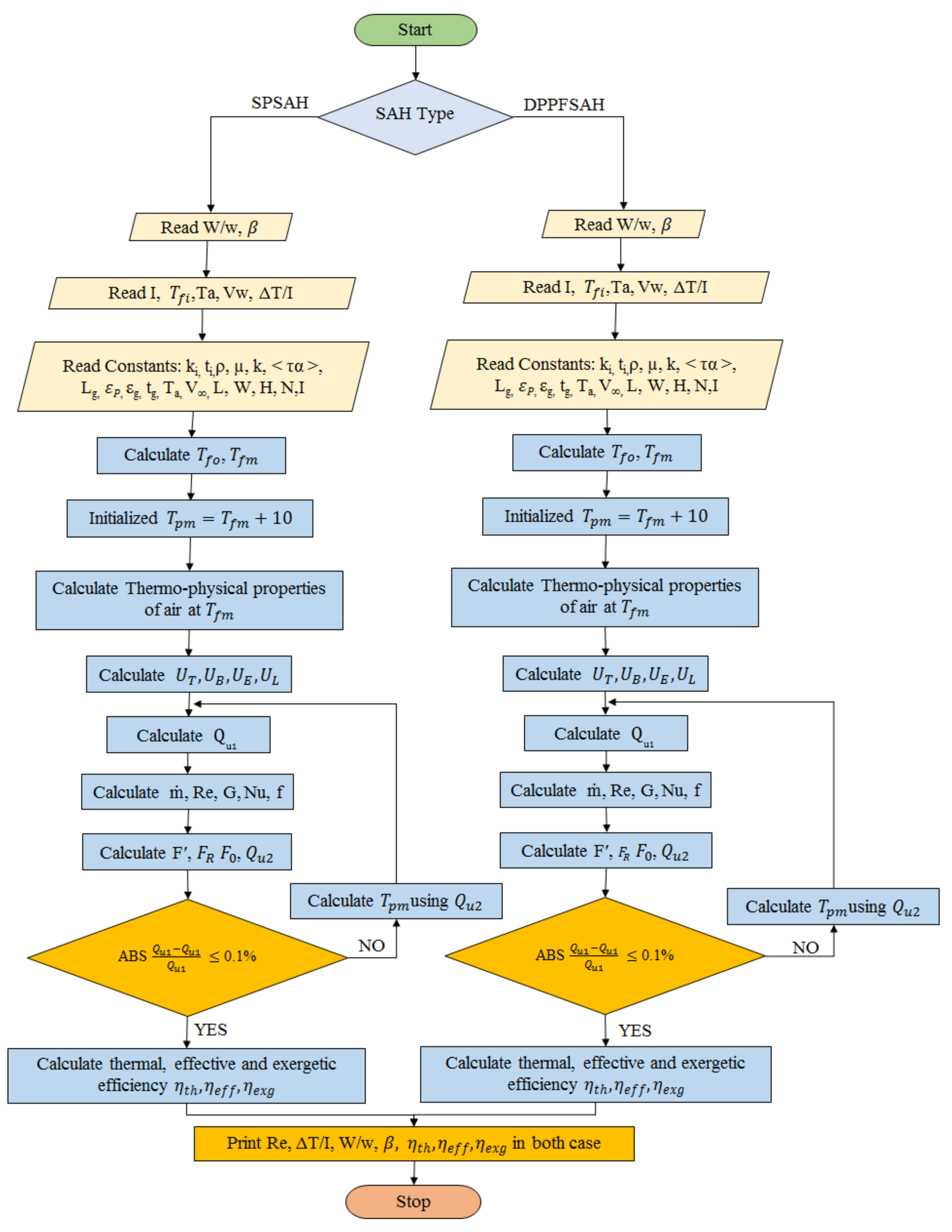
5. Steps for Efficiency Prediction of DPPFSAH
6. Results and Discussion
6.1. Effect of Flow and System Parameters on Thermal Efficiency
6.1.1. Effect of Reynolds Number (Re)
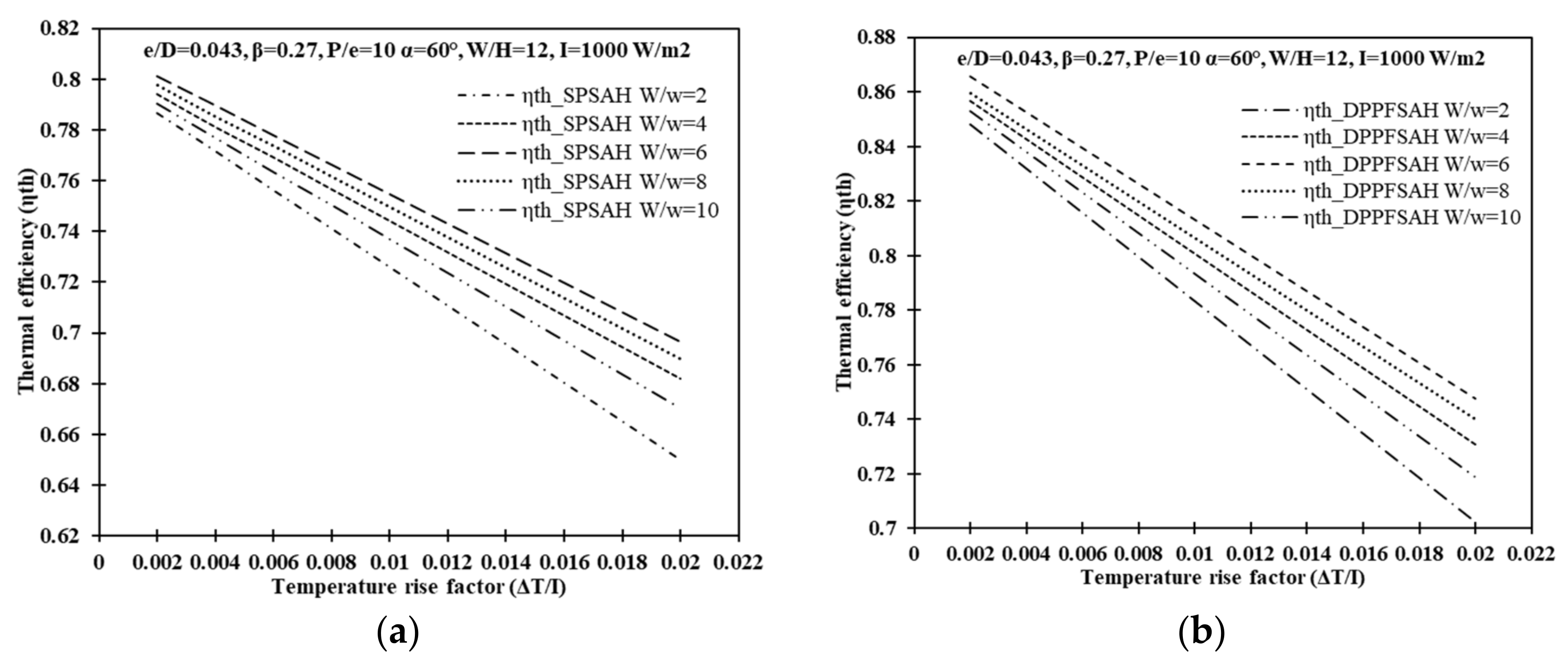
6.1.2. Effect of Relative Roughness Width (W/w)
6.1.3. Effect of Open Area Ratio (β)
6.2. Efficiency Enhancement Factor (EEF)
6.3. Effect of Insolation on EEF
7. Effective Efficiency (ηeff) Criteria for DPPFSAH
Geometric Parameter Optimization Using the Effective Efficiency Criteria
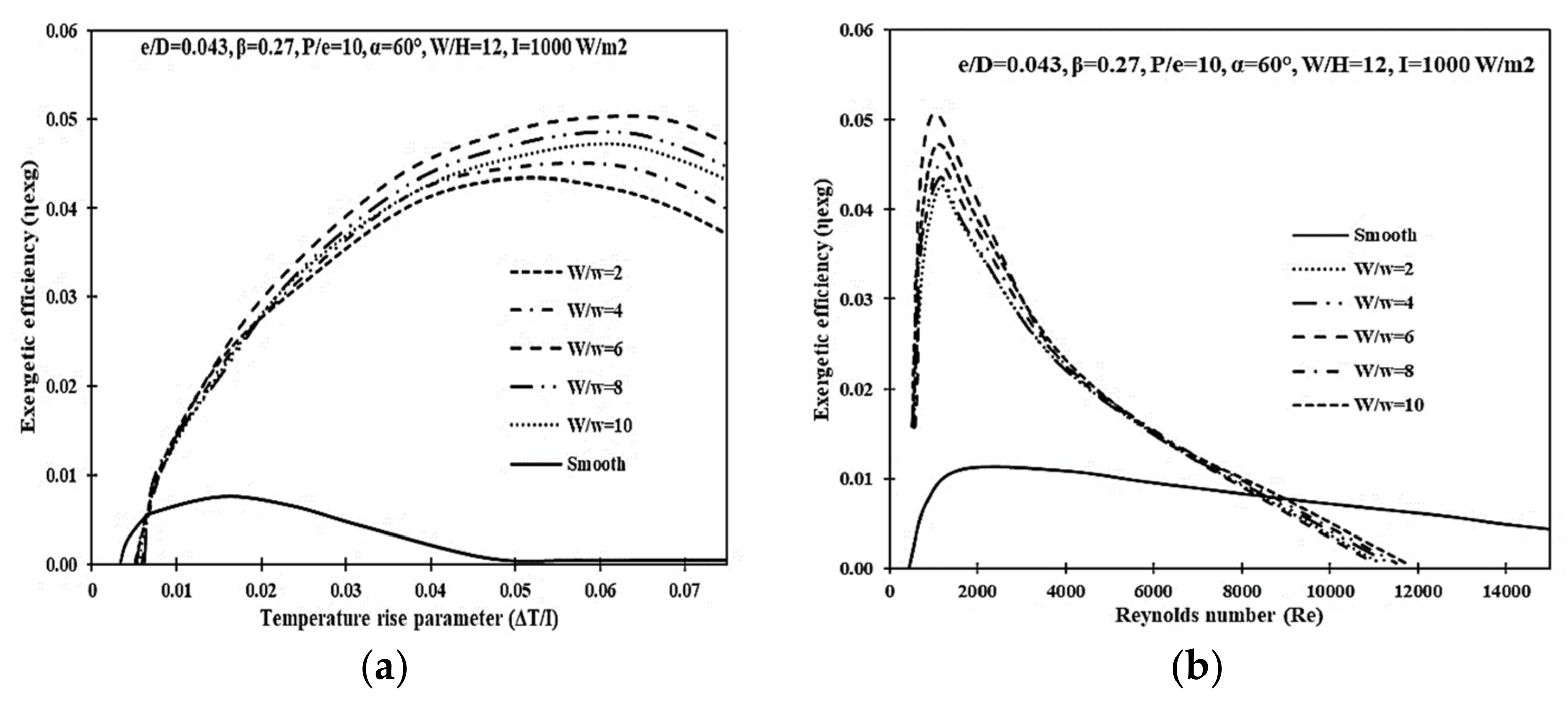
8. Exergetic Efficiency (ηexg) Criterion for DPPFSAH
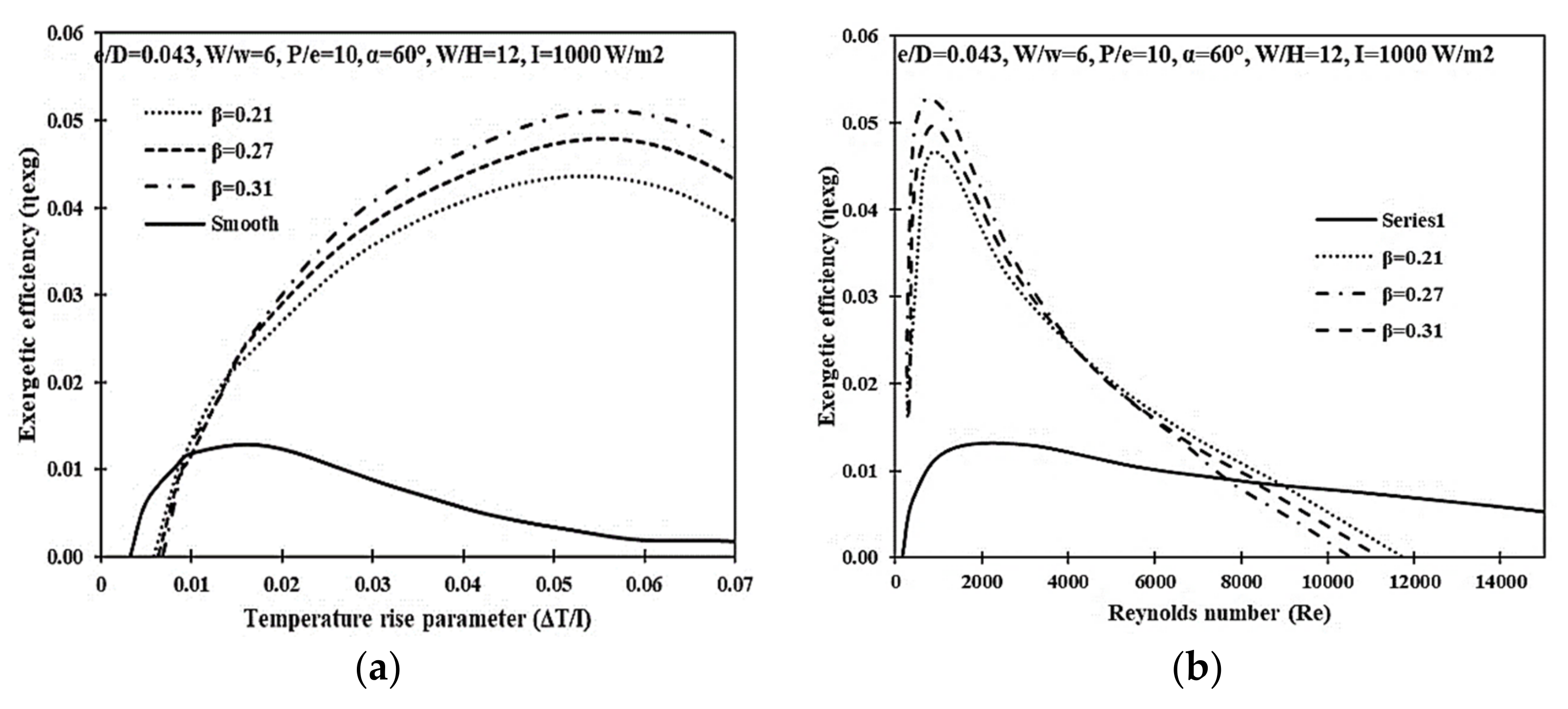
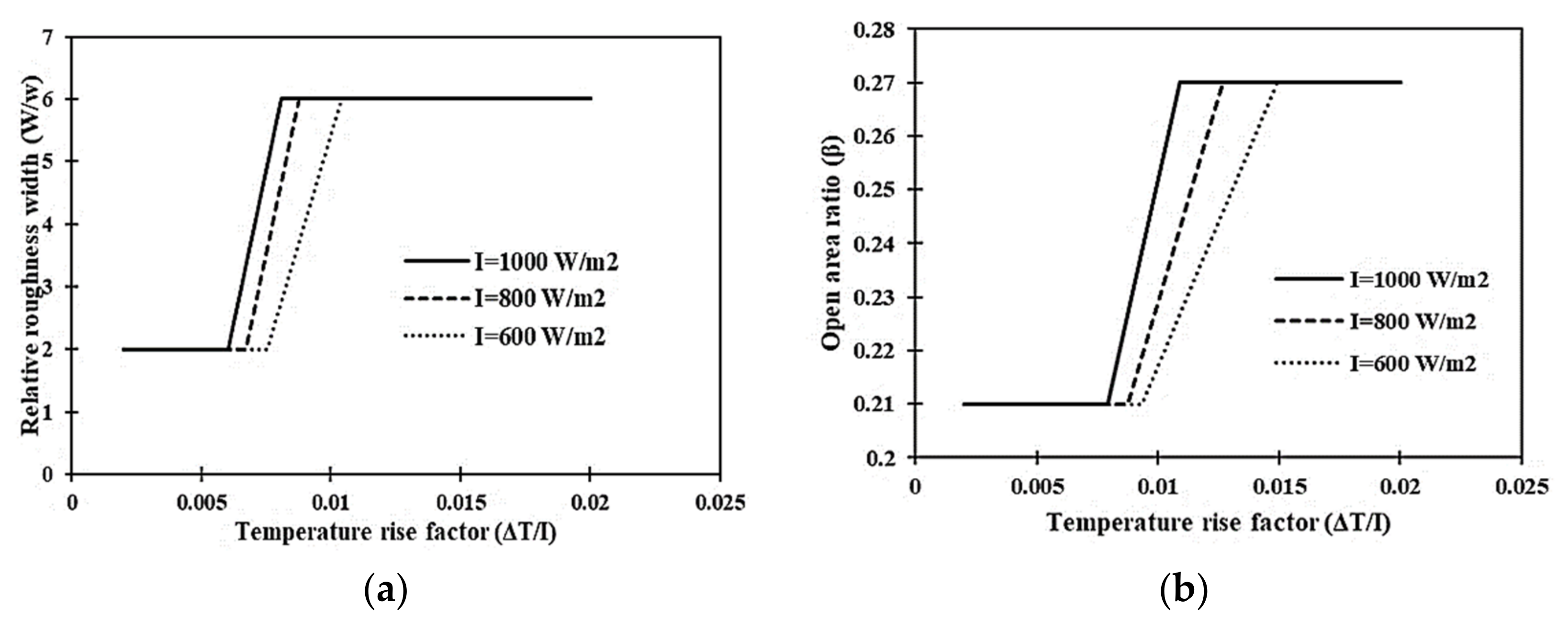
Geometric Parameter Optimization Using the Exergetic Efficiency (ηexg) Criterion
9. Comparison of Optimization Criteria
10. Conclusions
Author Contributions
Funding
Institutional Review Board Statement
Informed Consent Statement
Data Availability Statement
Conflicts of Interest
Nomenclature
| Details of symbols | Greek symbols | ||
| A | Area, (m2) | Δ | Drop/gradient |
| Cd | Coefficient of discharge | Δ | Partial |
| P | Mean static pressure N/m2 | η | Efficiency |
| H | Height, (m) | ∈ | Emissivity |
| h | Heat-transfer coefficient (W/m2·°C) | υ | Kinematic viscosity, (m2/s) |
| I | Solar Irradiance (W/m2) | α | Absorptivity |
| k | Thermal conductivity (W/m°C) | σ | Stefan–Boltzmann constant (W/m2·K4) |
| t | Thickness (m) | ρ | Air density, (kg/m3) |
| Air mass-flow rate, (kg/s) | α | Angle of attack, (o) | |
| P | Pitch distance (m) | β | Collector slope (o), Open area ratio |
| Q | Thermal energy transferred (J) | μ | Dynamic viscosity (N.s/m2) |
| 𝑞 | Average heat generation (W/m3) | ψ | Circularity |
| T | Mean Temperature (°C) | ν | Kinematic viscosity m2/s |
| W | Width of channel, (m) | τ | Transmissivity |
| w | Width of one set of rib, (m) | ||
| V | Velocity of working fluid (m/s) | Abbreviations | |
| Dh | Hydraulic diameter (m) | DPPF | Double-Pass Parallel Flow |
| Subscripts | THPP | Thermohydraulic performance parameter | |
| A | Ambient, Air | SAH | Solar Air Heater |
| abs | Absorber | ||
| Amb | Ambient | m | Mean |
| d | Duct/ channel, diameter | u | Useful |
| g | Glass cover | t | Thermal |
| h | Height, hole | eff | Effective |
| Ins | Insulation | ex. | Exergetic |
References
- Klein, S.A.; Beckman, W.A.; Duffie, J.A. A design procedure for solar air heating systems. Sol. Energy 1977, 19, 509–512. [Google Scholar] [CrossRef]
- Saini, M.; Sharma, A.; Singh, V.P.; Jain, S.; Dwivedi, G. Solar Thermal Receivers—A Review. Lect. Notes Mech. Eng. 2022, 2, 311–325. [Google Scholar] [CrossRef]
- Alam, T.; Meena, C.S.; Balam, N.B.; Kumar, A.; Cozzolino, R. Thermo-hydraulic performance characteristics and optimization of protrusion rib roughness in solar air heater. Energies 2021, 14, 3159. [Google Scholar] [CrossRef]
- Alam, T.; Kim, M.-H. Heat transfer enhancement in solar air heater duct with conical protrusion roughness ribs. Appl. Therm. Eng. 2017, 126, 458–469. [Google Scholar] [CrossRef]
- Singh, S. Experimental and numerical investigations of a single and double pass porous serpentine wavy wiremesh packed bed solar air heater. Renew. Energy 2020, 145, 1361–1387. [Google Scholar] [CrossRef]
- Ho, C.D.; Hsiao, C.F.; Chang, H.; Tien, Y.E. Investigation of Device Performance for Recycling Double-pass V-corrugated Solar Air Collectors. Energy Procedia 2017, 105, 28–34. [Google Scholar] [CrossRef]
- Fudholi, A.; Sopian, K.; Ruslan, M.H. Thermal Efficiency of Double Pass Solar Collector with Longitudinal Fins Absorbers Thermal Efficiency of Double Pass Solar Collector with Longitudinal Fins Absorbers. Am. J. Appl. Sci. 2011, 8, 254–260. [Google Scholar] [CrossRef]
- Kumar, A.; Akshayveer; Singh, A.P.; Singh, O.P. Efficient designs of double-pass curved solar air heaters. Renew. Energy 2020, 160, 1105–1118. [Google Scholar] [CrossRef]
- Yadav, K.D.; Prasad, R.K. Performance analysis of parallel flow flat plate solar air heater having arc shaped wire roughened absorber plate. Renew. Energy Focus 2020, 32, 23–44. [Google Scholar] [CrossRef]
- Hernández, A.L.; Quiñonez, J.E. Analytical models of thermal performance of solar air heaters of double-parallel flow and double-pass counter flow. Renew. Energy 2013, 55, 380–391. [Google Scholar] [CrossRef]
- Jain, S.; Gupta, J.; Singh, V.P. Analysis of the effect of perforation in multi-v rib artificial roughened single pass solar air heater:—Part A. Exp. Heat Transf. 2021, 1–20. [Google Scholar] [CrossRef]
- Gupta, J.; Singh, V.P.; Jain, S. Performance assessment of double-pass parallel flow solar air heater with perforated multi-V ribs roughness—Part B. Exp. Heat Transf. 2022, 1–18. [Google Scholar] [CrossRef]
- Singh, V.P.; Jain, S.; Gupta, J.M.L. Analysis of the effect of variation in open area ratio in perforated multi-V rib roughened single pass solar air heater—Part A. Energy Sources Part A Recover. Util. Environ. Eff. 2022, 1–20. [Google Scholar] [CrossRef]
- Singh, V.P.; Jain, S.; Kumar, A. Establishment of correlations for the Thermo-Hydraulic parameters due to perforation in a multi-V rib roughened single pass solar air heater. Exp. Heat Transf. 2022, 1–20. [Google Scholar] [CrossRef]
- Karwa, R.; Maheshwari, B.K.K. Heat transfer and friction in an asymmetrically heated rectangular duct with half and fully perforated baffles at different pitches. Int. Commun. Heat Mass Transf. 2009, 36, 264–268. [Google Scholar] [CrossRef]
- Kwak, J.S.; Shin, S. Effect of hole shape on the heat transfer in a rectangular duct with perforated blockage walls. J. Mech. Sci. Technol. 2008, 22, 1945–1951. [Google Scholar] [CrossRef]
- Alam, T.; Saini, R.P.; Saini, J.S. Effect of circularity of perforation holes in V-shaped blockages on heat transfer and friction characteristics of rectangular solar air heater duct. Energy Convers. Manag. 2014, 86, 952–963. [Google Scholar] [CrossRef]
- Bahuguna, R.; Mer, K.K.S.; Kumar, M.; Chamoli, S. Entropy generation analysis in a tube heat exchanger integrated with triple blade vortex generator inserts. Energy Sources Part A Recover. Util. Environ. Eff. 2021, 1–19. [Google Scholar] [CrossRef]
- Chamoli, S.; Thakur, N.S. Heat transfer enhancement in solar air heater with V-shaped perforated baffles. J. Renew. Sustain. Energy 2013, 5, 023122. [Google Scholar] [CrossRef]
- Tariq, A.; Panigrahi, P.K.; Muralidhar, K. Flow and heat transfer in the wake of a surface-mounted rib with a slit. Exp. Fluids 2004, 37, 701–719. [Google Scholar] [CrossRef]
- Duffie, J.A.; Beckman, W.A.; Winston, R.; Kreith, F. Solar Energy Thermal Processes. Phys. Today 1976, 29, 62–67. [Google Scholar] [CrossRef]
- Phu, N.M.; Bao, T.T.; Hung, H.N.; Tu, N.T.; van Hap, N. Analytical predictions of exergoeconomic performance of a solar air heater with surface roughness of metal waste. J. Therm. Anal. Calorim. 2020, 144, 1727–1740. [Google Scholar] [CrossRef]
- Phu, N.M.; Thao, P.B.; van Hap, N. Effective efficiency assessment of a solar air heater having baffles spaced with different successive ratios. Case Stud. Therm. Eng. 2021, 28, 101486. [Google Scholar] [CrossRef]
- Phu, N.M.; van Hap, N. Performance Evaluation of a Solar Air Heater Roughened with Conic-Curve Profile Ribs Based on Efficiencies and Entropy Generation. Arab. J. Sci. Eng. 2020, 45, 9023–9035. [Google Scholar] [CrossRef]
- van Hap, N.; Phu, N.M. Heat Transfer in Double-Pass Solar Air Heater: Mathematical Models and Solution Strategy; IntechOpen: London, UK, 2022. [Google Scholar]
- Phu, N.M.; Tu, N.T.; van Hap, N. Thermohydraulic performance and entropy generation of a triple-pass solar air heater with three inlets. Energies 2021, 14, 6399. [Google Scholar] [CrossRef]
- Kumar, A.; Saini, R.P.P.; Saini, J.S.S. Development of correlations for Nusselt number and friction factor for solar air heater with roughened duct having multi v-shaped with gap rib as arti fi cial roughness. Renew. Energy 2013, 58, 151–163. [Google Scholar] [CrossRef]
- Sharma, A.; Bharadwaj, G.; Varun. Heat transfer and friction factor correlation development for double-pass solar air heater having V-shaped ribs as roughness elements. Exp. Heat Transf. 2017, 30, 77–90. [Google Scholar] [CrossRef]
- Ravi, R.K.; Saini, R.P. Nusselt number and friction factor correlations for forced convective type counter flow solar air heater having discrete multi V shaped and staggered rib roughness on both sides of the absorber plate. Appl. Therm. Eng. 2018, 129, 735–746. [Google Scholar] [CrossRef]
- Patel, S.S.; Lanjewar, A. Exergy based analysis of solar air heater duct with W-shaped rib roughness on the absorber plate. Arch. Thermodyn. 2019, 40, 21–48. [Google Scholar] [CrossRef]
- Kumar, B.; Patil, A.K.; Jain, S.; Kumar, M. Effects of Double V Cuts in Perforated Twisted Tape Insert: An Experimental Study. Heat Transf. Eng. 2020, 41, 1473–1484. [Google Scholar] [CrossRef]
- Raj, B.P.; Meena, C.S.; Agarwal, N.; Saini, L.; Hussain Khahro, S.; Subramaniam, U.; Ghosh, A. A review on numerical approach to achieve building energy efficiency for energy, economy and environment (3e) benefit. Energies 2021, 14, 4487. [Google Scholar] [CrossRef]
- Kumar, R.; Kumar, A.; Goel, V. Performance improvement and development of correlation for friction factor and heat transfer using computational fluid dynamics for ribbed triangular duct solar air heater. Renew. Energy 2019, 131, 788–799. [Google Scholar] [CrossRef]
- Gupta, B.; Manikpuri, G.P.; Waiker, J.K.; Pandya, M. Experimental Investigation of Double Pass Solar Air Heater using different type of Porous Media. Int. J. Curr. Eng. Technol. 2013, 3, 2006–2009. [Google Scholar]
- Alam, T.; Kim, M.-H. A critical review on artificial roughness provided in rectangular solar air heater duct. Renew. Sustain. Energy Rev. 2017, 69, 387–400. [Google Scholar] [CrossRef]
- Meena, C.S.; Raj, B.P.; Saini, L.; Agarwal, N. Performance Optimization of Solar-Assisted Heat Pump System for Water Heating Applications. Energies 2021, 14, 3534. [Google Scholar] [CrossRef]
- Klein, S.A.; Duffie, J.A.; Beckman, W.A. Transient considerations of flat-plate solar collectors. J. Eng. Gas Turbines Power 1974, 96, 109–113. [Google Scholar] [CrossRef]
- Bliss, R.W. The derivations of several ‘Plate-efficiency factors’ useful in the design of flat-plate solar heat collectors. Sol. Energy 1959, 3, 55–64. [Google Scholar] [CrossRef]
- Agarwal, V.K.; Larson, D.C. Calculation of the top loss coefficient of a flat-plate collector. Sol. Energy 1981, 27, 69–71. [Google Scholar] [CrossRef]
- Klein, S.A. Calculation of flat-plate collector loss coefficients. Sol. Energy 1975, 17, 79–80. [Google Scholar] [CrossRef]
- Beckman, W.; Bugler, J.; Cooper, P.; Duffie, J.; Dunkle, R.; Glaser, P.; Horigome, T.; Howe, E.; Lawand, T.; Van Der Mersch, P.; et al. Units and symbols in solar energy. Sol. Energy 1978, 21, 65–68. [Google Scholar] [CrossRef]
- Garg, H.P.; Datta, G. The top loss calculation for flat plate solar collectors. Sol. Energy 1984, 32, 141–143. [Google Scholar] [CrossRef]
- Akhtar, N.; Mullick, S.C. Approximate method for computation of glass cover temperature and top heat-loss coefficient of solar collectors with single glazing. Sol. Energy 1999, 66, 349–354. [Google Scholar] [CrossRef]
- Mullick, S.C.; Nanda, S.K. An improved technique for computing the heat loss factor of a tubular absorber. Sol. Energy 1989, 42, 1–7. [Google Scholar] [CrossRef]
- Kumar, S.; Mullick, S.C. Wind heat transfer coefficient in solar collectors in outdoor conditions. Sol. Energy 2010, 84, 956–963. [Google Scholar] [CrossRef]
- Cortes, A.; Piacentini, R. Improvement of the Efficiency of a Bare Solar Collector by Means of Turbulence Promoters. Appl. Energy 2000, 36, 253–261. [Google Scholar] [CrossRef]
- Shetty, S.P.; Paineni, A.; Kande, M.; Madhwesh, N.; Sharma, N.Y.; Karanth, K.V. Experimental investigations on a cross flow solar air heater having perforated circular absorber plate for thermal performance augmentation. Sol. Energy 2020, 197, 254–265. [Google Scholar] [CrossRef]
- Altfeld, K. Second law optimization of flat-plate solar air heaters Part I: The concept of net exergy flow and the modeling of solar air heaters. Sol. Energy 1988, 41, 127–132. [Google Scholar] [CrossRef]

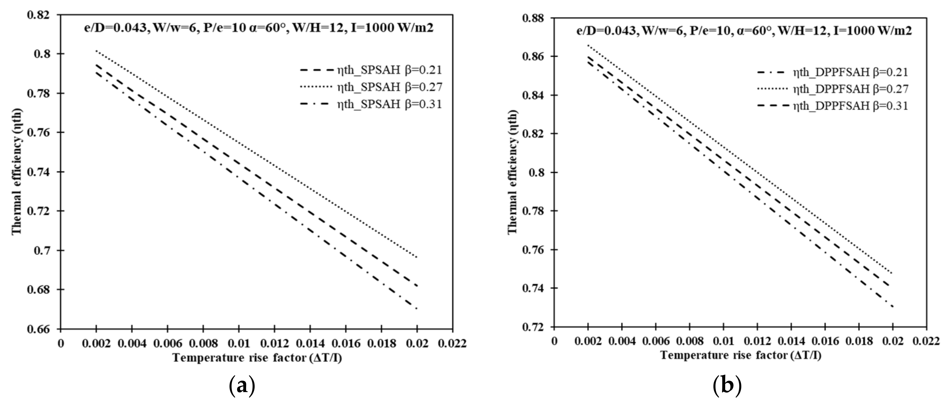

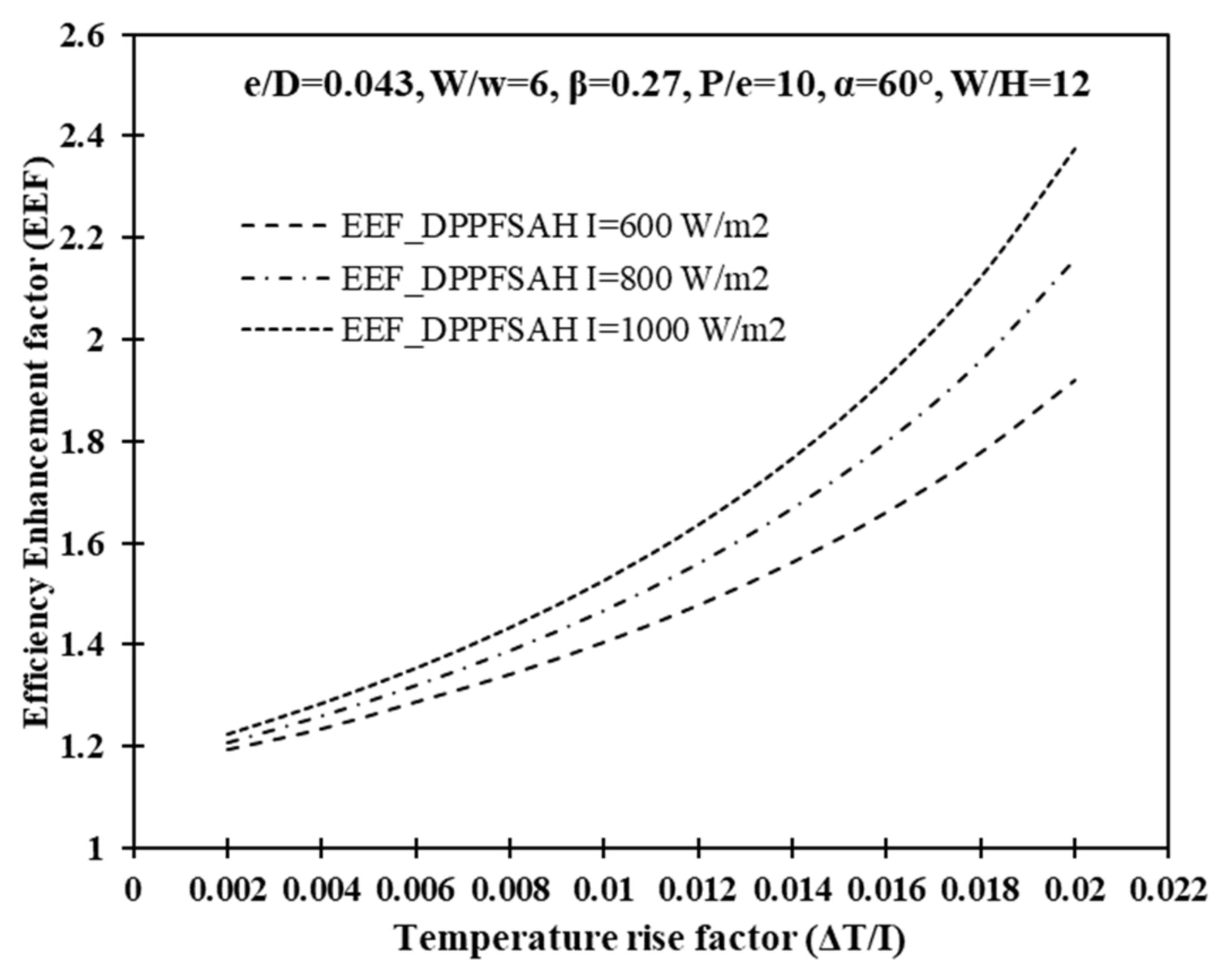

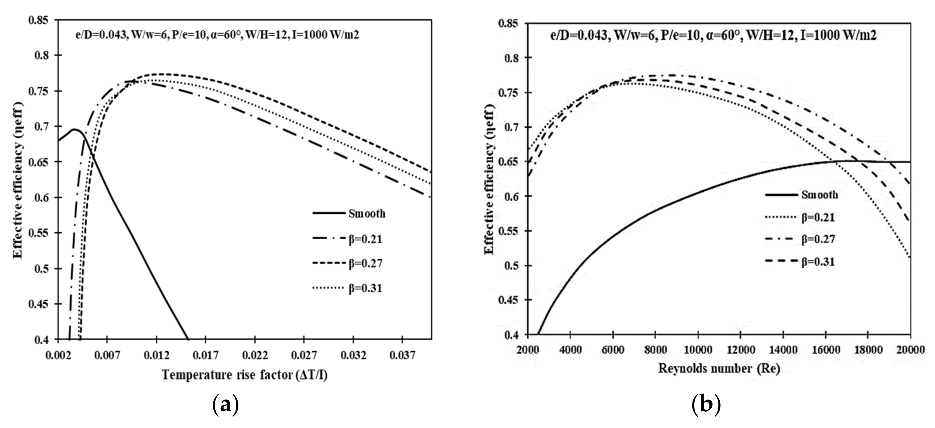
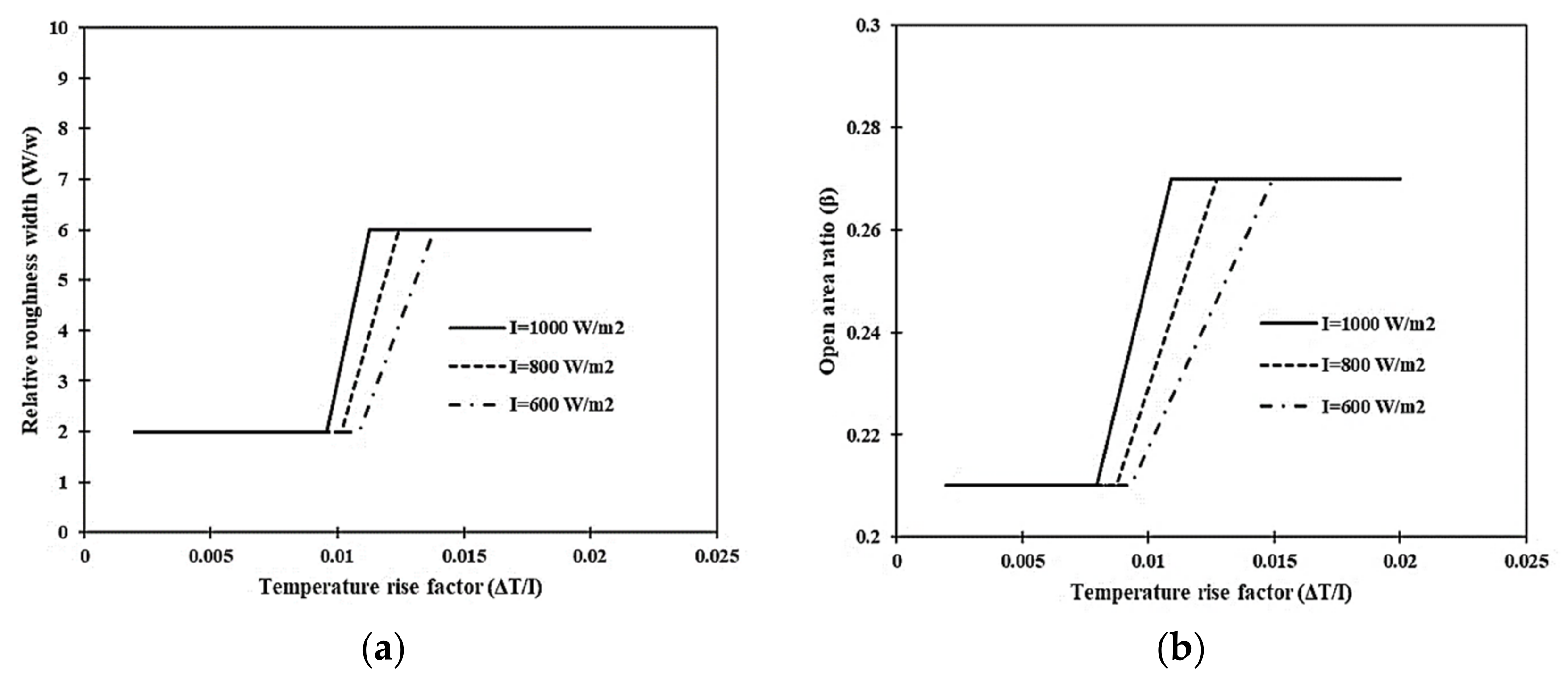

| S. No. | Parameter | Value/Range |
|---|---|---|
| 1. | No. of Pass | Two (DPPF) |
| 2. | Type of Flow | Parallel Flow |
| 3. | L | 1.0 m |
| 4. | W | 0.3 m |
| 5. | H | 0.025 m |
| 6. | N | 1 nos. |
| 7. | kins | 0.037 W/m-K |
| 8. | tins | 0.05 m |
| 9. | ρ | 1.105 kg/m3 |
| 10. | µ | 1.865 × 10⁻⁵ kg/s-m |
| 11. | k | 0.02624 W/m-K |
| 12. | τα | 0.8 |
| 12. | Hg | 0.025 m |
| 13. | β | 0 for horizontal |
| 14. | 𝜀𝑃 | 0.92 |
| 15. | εg | 0.88 |
| 16. | tg | 0.004 m |
| 17. | Ta | 300 K |
| 18. | V | 1.0 m/s |
| Sr. No. | Parameters Notations | Range |
|---|---|---|
| 1. | W/w | 2–10 (five values) |
| 2. | β | 0.0, 0.21, 0.27, 0.31 (four values) |
| 3. | Re | 2000–18,000 (Nine Values) |
| 4. | ΔT/I | 0.002–0.02 Km2/W (Ten Values) |
| 5. | I | 600–1000 W/m2 (Three values) |
| Geometric Parameter | ΔT/I (Km2/W) | β |
|---|---|---|
| β | 0.00359 < ΔT/I < 0.00794 | 0.21 |
| 0.01091 < ΔT/I | 0.27 | |
| 0.00794 < ΔT/I < 0.01091 | 0.31 | |
| ΔT/I < 0.00359 | Smooth | |
| Geometric Parameter | Re | β |
| β | Re < 5644 | 0.21 |
| 5860 < Re < 18,821 | 0.27 | |
| 5557 < Re < 8527 | 0.31 | |
| 18,821 < Re | Smooth |
| Geometric Parameter | ΔT/I (Km2/W) | W/w |
|---|---|---|
| W/w | 0.00835 < ΔT/I < 0.01126 | 10 |
| 0.00815 < ΔT/I < 0.01128 | 8 | |
| 0.01128 < ΔT/I | 6 | |
| 0.00823 < ΔT/I < 0.01117 | 4 | |
| 0.00371 < ΔT/I < 0.01128 | 2 | |
| ΔT/I < 0.00371 | Smooth | |
| Geometric Parameter | Re | W/w |
| W/w | Re < 7239 | 10 |
| 8527 < Re < 8741 | 8 | |
| 11,881 < Re < 19,025 | 6 | |
| 7239 < Re < 8527 | 4 | |
| 5644 < Re < 8527 | 2 | |
| 19,025 < Re | Smooth |
| Geometric Parameters | ΔT/I (Km2/W) | W/w (Optimum) |
|---|---|---|
| W/w | ΔT/I < 0.009572 | 2 |
| 0.009572 < ΔT/I < 0.01058 | Function of ΔT/I of I | |
| 0.01058 < ΔT/I | 6 | |
| Geometric Parameters | ΔT/I (Km2/W) | β (Optimum) |
| β | ΔT/I < 0.00794 | 0.21 |
| 0.00794 < ΔT/I < 0.01091 | Function of ΔT/I of I | |
| 0.01091 < ΔT/I | 0.27 |
| Geometric Parameter | ΔT/I (Km2/W) | W/w |
|---|---|---|
| W/w | 0.05021 < ΔT/I < 0.06134 | 10 |
| 0.049893 < ΔT/I < 0.06134 | 8 | |
| 0.015298 < ΔT/I | 6 | |
| 0.04989 < ΔT/I < 0.06117 | 4 | |
| 0. 0.0059 < ΔT/I < 0.00871 | 2 | |
| ΔT/I < 0.006985 | Smooth | |
| Geometric Parameter | Re | W/w |
| W/w | 605 < Re < 1075 | 10 |
| 634 < Re < 1104 | 8 | |
| Re < 3685 | 6 | |
| 783 < Re < 1175 | 4 | |
| 6207 < Re < 8371 | 2 | |
| 9228 < Re | Smooth |
| Geometric Parameter | ΔT/I, Km2/W | β |
|---|---|---|
| β | 0.00919 < ΔT/I < 0.01279 | 0.21 |
| 0.0169 < ΔT/I | 0.27 | |
| 0.04055 < ΔT/I < 0.05271 | 0.31 | |
| ΔT/I < 0.00359 | Smooth | |
| Geometric Parameter | Re | β |
| β | 6182 < Re < 7930 | 0.21 |
| Re < 4052 | 0.27 | |
| 588 < Re < 937 | 0.31 | |
| 8503 < Re | Smooth |
| Rib Roughness Parameter | ΔT/I (Km2/W) | W/w (Optimum Value) |
|---|---|---|
| W/w | ΔT/I < 0.006051 | 2 |
| 0.006051 < ΔT/I < 0.008084 | Function of ΔT/I of I | |
| 0.008084 <ΔT/I | 6 | |
| Rib Roughness Parameter | ΔT/I (Km2/W) | β (Optimum Value) |
| β | ΔT/I < 0.00827 | 0.21 |
| 0.00827 < ΔT/I < 0.0169 | Function of ΔT/I of I | |
| 0.0169 < ΔT/I | 0.27 |
| Rib Roughness Parameter | ΔT/I (Km2/W) | Rib Roughness Parameter (Optimum Value) |
|---|---|---|
| W/w | ΔT/I < 0.006051 | 2 |
| ΔT/I > 0.01128 | 6 | |
| β | ΔT/I < 0.00794 | 0.21 |
| ΔT/I > 0.01693 | 0.27 |
| Insolation (W/m2) | Roughness Parameter | Range of ΔT/I |
|---|---|---|
| 1000 | W/w | 0.006051 < ΔT/I < 0.008084 |
| β | 0.0079413 < ΔT/I < 0.010914 | |
| 800 | W/w | 0.006719 < ΔT/I < 0.008799 |
| β | 0.008753 < ΔT/I < 0.012713 | |
| 600 | W/w | 0.007528 < ΔT/I < 0.010399 |
| β | 0.009325 < ΔT/I < 0.014937 |
Publisher’s Note: MDPI stays neutral with regard to jurisdictional claims in published maps and institutional affiliations. |
© 2022 by the authors. Licensee MDPI, Basel, Switzerland. This article is an open access article distributed under the terms and conditions of the Creative Commons Attribution (CC BY) license (https://creativecommons.org/licenses/by/4.0/).
Share and Cite
Singh, V.P.; Jain, S.; Karn, A.; Kumar, A.; Dwivedi, G.; Meena, C.S.; Cozzolino, R. Mathematical Modeling of Efficiency Evaluation of Double-Pass Parallel Flow Solar Air Heater. Sustainability 2022, 14, 10535. https://doi.org/10.3390/su141710535
Singh VP, Jain S, Karn A, Kumar A, Dwivedi G, Meena CS, Cozzolino R. Mathematical Modeling of Efficiency Evaluation of Double-Pass Parallel Flow Solar Air Heater. Sustainability. 2022; 14(17):10535. https://doi.org/10.3390/su141710535
Chicago/Turabian StyleSingh, Varun Pratap, Siddharth Jain, Ashish Karn, Ashwani Kumar, Gaurav Dwivedi, Chandan Swaroop Meena, and Raffaello Cozzolino. 2022. "Mathematical Modeling of Efficiency Evaluation of Double-Pass Parallel Flow Solar Air Heater" Sustainability 14, no. 17: 10535. https://doi.org/10.3390/su141710535
APA StyleSingh, V. P., Jain, S., Karn, A., Kumar, A., Dwivedi, G., Meena, C. S., & Cozzolino, R. (2022). Mathematical Modeling of Efficiency Evaluation of Double-Pass Parallel Flow Solar Air Heater. Sustainability, 14(17), 10535. https://doi.org/10.3390/su141710535


