1. Introduction
The consideration and control of temperature effects are of great significance in bridge design and construction, with calculation and analysis necessary in order to ensure structural safety. At present, design specifications mainly determine the temperature load by specifying the overall rise and fall of the structure’s temperature, gradient temperature in the main girder, and temperature differences in different components. Chinese specification [
1,
2] considers only the overall temperature in steel structures, which includes a maximum and a minimum over a prescribed period. For bridges with stayed cables, it also considers a temperature difference of ±10 °C between the cables and the main girder. BS5400 [
3] not only considers the overall temperature, but in the height direction of the steel section it also considers the differences in temperature between the top surface and other levels. Eurocode [
4] specifies that the thermal actions on a structural element consist of a uniform temperature, a linearly varying temperature, and a temperature difference among different components. In general, the current specifications consider the value of temperature load to be constant or gradient, but the actual temperature field distribution in a bridge construction is nonuniform and time-dependent. The temperature model in the design specification cannot reflect the real state of the temperature field at any given time in the bridge’s natural environment, nor can it reflect the influence of regional climate, or the particular structural form of the bridge. Therefore, design strategy can rarely be specified for particular situations.
With the on-going investigation of temperature load, temperature distribution research was developed from a linear form to a nonlinear form, with the actual influence of solar radiation, wind speed, and other environmental factors on the structures gradually taken into consideration [
5,
6]. Guoping Xia et al. [
7] studied the influence of overall temperature rises, component temperature differences, and the effects of sunshine on pylons, cables, and girders. Significant temperature effects on different structural forms was investigated. With the application of finite element technology, research on bridge temperature fields and its corresponding effect is more refined. Tome E et al. [
8] proposed a temperature response simulation method for large concrete bridge structures, considering the effect of actual temperature changes. Jinsong Zhu [
9] studied the spatial distribution of temperature on different components of a long-span suspension bridge. The problem of solar radiation shielding between complex components was considered, and the spatial temperature field of a long-span suspension bridge was calculated by transforming time-varying shielding features of the geometric position of each component into thermal boundary. Research provides a feasible approach for determining the equivalent thermal boundary conditions of structures with environmental parameters, acting as a basis for fine analysis of the temperature field and temperature load of bridges [
10,
11]. Recently, scholars have applied intelligent algorithms to temperature field simulations. Fan Jiansheng et al. [
12,
13] proposed a MATLAB-based state equation solving method to implement the one-dimensional efficient numerical model, which provides a powerful tool for analyzing the temperature field and thermal effects.
In this paper, an inclined steel arch bridge is investigated as a case study and deformation induced by periodical temperature changes in the steel structure, which was exposed to the environment, is studied. Firstly, the theory of temperature field analysis is reviewed, and the approach to determining environmental parameters and heat transfer boundary conditions is introduced. Secondly, taking the inclined single-side suspension steel arch bridge as an example, a refined time-dependent temperature field of bridge components is analyzed. The structural temperature effect under the action of the specification load mode, and the real temperature field, is calculated and a detailed comparison is made between them. Finally, a method of standard load combination is proposed to synchronously combine the temperature effect of multiple components, so as to verify the feasibility of load combination in determining the most unfavorable situation of the effect of a real temperature field.
2. Theory of Thermal Boundary Condition
2.1. Environmental Parameter
In the simulation of a structural temperature field, environmental parameters including local temperature, wind speed, and solar factors are considered [
14,
15]. Environmental temperature (unit is degrees Celsius) and wind speed (unit is
) can be obtained from monitoring data. Solar factors mainly include direct radiation intensity
, scattering radiation intensity
, and reflected radiation intensity
. The direct solar radiation
refers to the radiation of sunlight reaching the earth’s surface in the form of parallel rays, and commonly uses the Bouguer Equation (1) [
16] for simple calculation. The intensity of direct solar radiation decreases significantly when passing through the atmosphere, so the degree of attenuation is related to the distance
(unit is m) of sunlight passing through the atmosphere and the atmospheric transparency
(unit is 1).
where
is direct solar radiation of the horizontal plane in
,
is solar constant in
,
is solar altitude angle in degrees,
is the projection angle of sunlight on the inclined plane in degrees. See Reference [
17] for details of the definition and calculation formulas of
and
.
The scattering radiation intensity
is always accompanied by direct solar radiation, and part of its power will diffuse to the ground through gas and dust, which causes thermal reactions of structures. The scattering intensity can be calculated by Equation (2) [
17].
where
is the scattering intensity of horizontal plane in
,
is the included angle between normal plane and horizontal plane of the radiation plane in degrees.
The reflected radiation intensity
refers to the intensity of solar radiation reflected by the earth’s surface, and can be calculated by Equation (3) [
17].
where
(unit is 1) is the surface reflectance,
is the included angle between the light and the ground in degrees.
The direct solar radiation, scattering radiation intensity, and reflected radiation intensity in the equations presented above are all in . According to these solar factors, the total solar radiation, which induces the temperature field of the structural cross-section, can be determined for subsequent simulation.
2.2. Setting of Thermal Boundary
For bridge structure, temperature field is mainly determined by thermal boundary, so the definition and setting of the thermal boundary is of great significance for structural analysis. With different construction locations, the natural environment and the weather system which structures face are quite different. Therefore, the boundary of the component should be set based on actual environmental parameters.
The convective heat transfer coefficient
(unit is
) represents the heat exchange ability between fluid and solid surface, which can be defined by the heat exchange within a specified time and area with 1 °C temperature difference. Its value is closely related to the physical properties of the fluid, the shape and position of the heat transfer surface, and the flow rate of the fluid in the process of heat transfer. The greater the velocity near the surface, the larger the heat transfer coefficient. The coefficient can be calculated as Equation (4) [
18].
where
is the actual wind speed on the surface of the component, in
.
The radiant heat transfer coefficient
(unit is
) is the rate at which an object emits or absorbs radiation, which is related to the surface temperature of the structure and the surrounding environment, and can be calculated as Equation (5) [
19].
where
is the ambient temperature, in degrees Celsius.
The comprehensive heat transfer coefficient
(unit is
) refers to the convective and radiative heat exchange between the component and the external environment. When calculating the temperature field of a component, the convective heat transfer coefficient and the radiation heat transfer coefficient are generally considered together as the comprehensive heat transfer coefficient. On the interior surface of the component box, only the convection heat transfer of the air inside the box is considered, and can be written as Equation (6) [
20].
The temperature field of bridge components is obtained by solving the thermal differential equation. There are three kinds of thermal boundary conditions for solving the differential equation of thermal conductivity, which is also the basis influencing the temperature field of components. The main factors affecting the boundary conditions are environmental temperature, solar radiation, and surface convection. Wang [
21] pointed out that the comprehensive temperature coefficient representing the influence of environmental comprehensive factors on structure includes the influence of environmental temperature, solar radiation, and structure surface convection on bridge components. The details are described in [
11].
where
is the comprehensive temperature of the component, in degrees Celsius;
is the ambient temperature, in degrees Celsius;
(unit is 1) is the heat absorption coefficient of structural surface thermal radiation;
is the intensity of structural surface thermal radiation, in
;
is the convective heat transfer coefficient.
Based on setting the above heat transfer boundary conditions and comprehensive indicators, the actual temperature field of the component can be simulated. Taking a single-side suspension steel pedestrian arch bridge in Xiamen as an example, the refined temperature field of components is analyzed and the temperature effect is calculated.
3. Finite Element Simulation of Bridge
3.1. Engineering Project Background
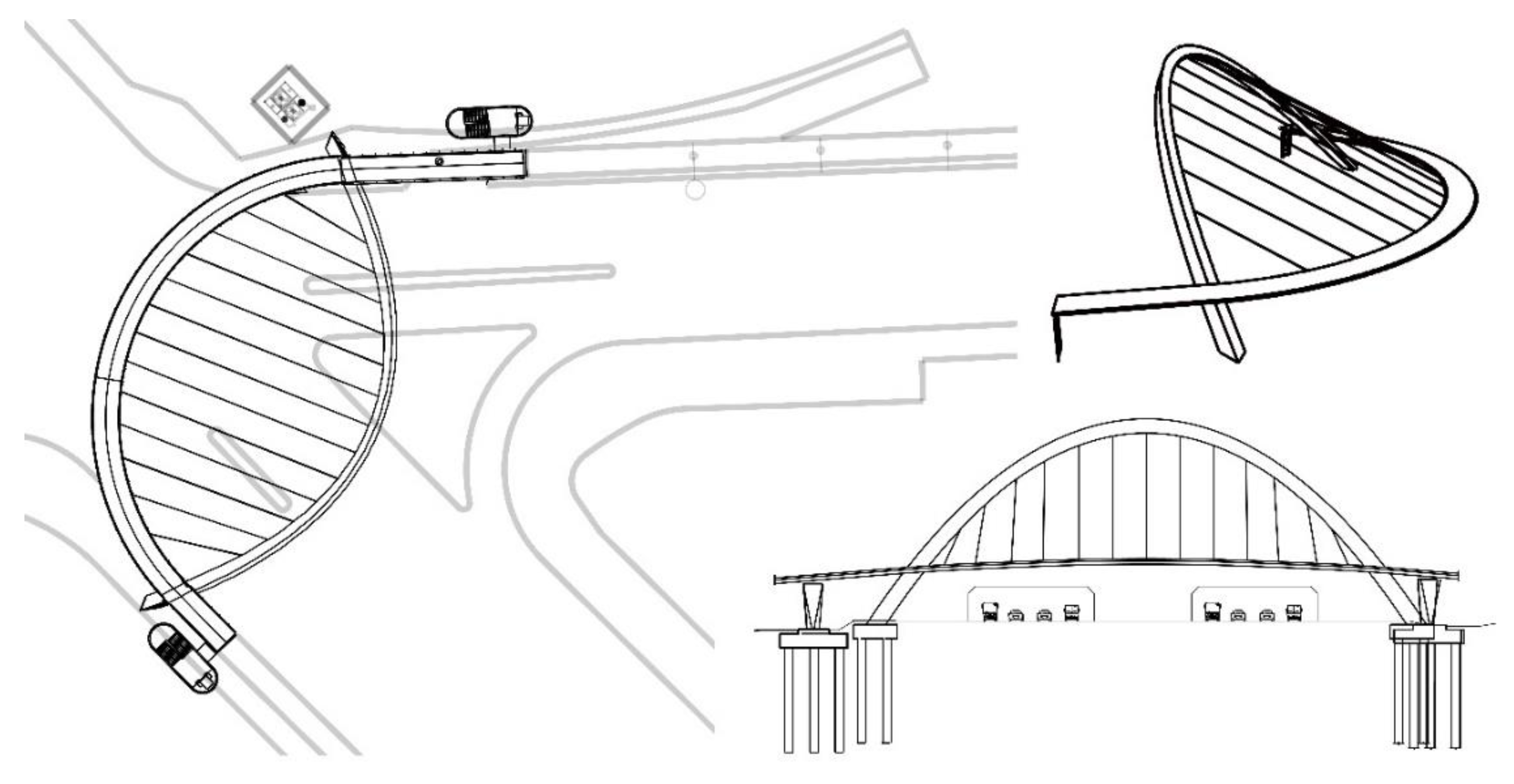
Yuanshan Bridge is a single-side suspension curvilinear basket arch bridge, located in Xiamen, China. The total length of the bridge is about 130 m, and the span layout is 10.49 m (southern side) + 91.92 m + 27.43 m (northern side). The side spans are built in the form of continuous beam structures, and the main span is an inclined single-side suspension arch bridge. The main arch of the bridge is 29 m high with an out-of-plane tilt of about 28°. The plane of the main span girder is on an arc with a radius of 37.16 m, and the total width of the bridge deck is 4.4 m. The bridge deck and the arch are connected by cables with a spacing of 5 m, and the inclined angles of hangers range from 23° to 28°. Layout of the Yuanshan Bridge Project is shown in
Figure 1.
The cross-section of the arch is designed as a steel box. The height and width of the section decrease linearly from the arch foot to the dome. The main girder adopts a flat steel box structure. The girder is 0.8 m in height, the plate thickness is 22 mm, the top plate of standard section is 4.0 m in width, and the bottom plate is 0.9 m in width. The hanger is sealed with a diameter of 50 mm. Typical sections of arch and girder are shown in
Figure 2.
3.2. FE Modeling of Bridge
Commercially available program, ANSYS, and Parametric Design Language (APDL) are used to set up finite element models for simulation of refined time-dependent temperature field. This program is capable of carrying out both static and dynamic analyses, which could realize the temperature simulation as a transient analysis.
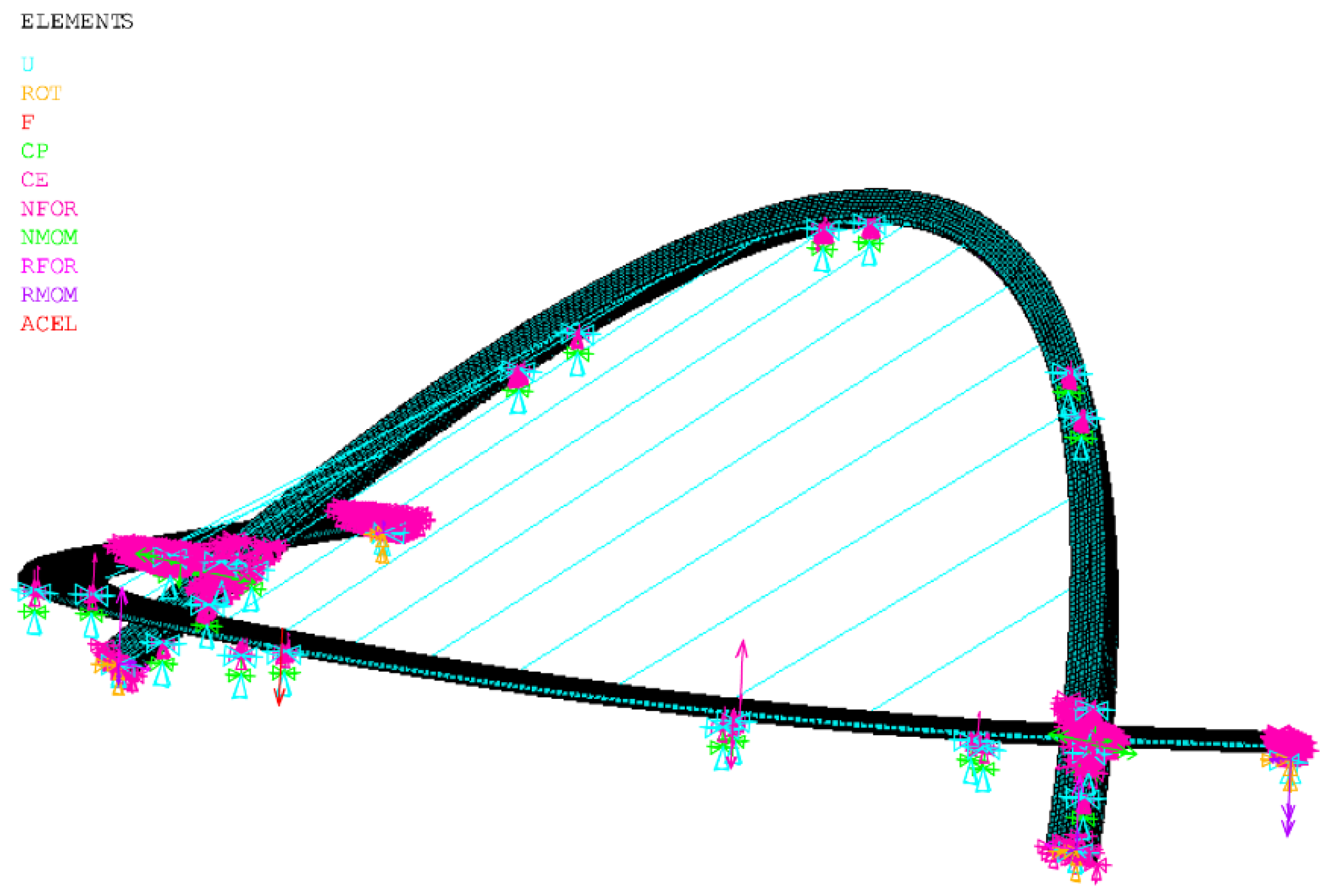
The main components of the inclined single-side suspension steel arch bridge are: arch rib, girder, hanger, crossbeam, and lateral bracing. These elements are all made from one main material: steel, which has a mass density of 7850 kg/m3, modulus of elasticity of 21.1 GPa and Poisson ratio 0.25. In general, for the FE modeling of the bridge by using ANSYS program, quadrilateral 4 nodes SHELL181 element is used for representation of steel components, and LINK180 element for modeling of the hanger.
To achieve connection between components, two ends of the hangers respectively share the same nodes at the surface of the arch and beam, and rigid connections are used to connect the main beam and the arch rib. Vertical force is transmitted to the abutment, and finally to the foundation, through the cable and rigid connection between arch and beam. The horizontal force is transmitted to supports, and finally to the foundation through the abutment piers at the anchoring span, and the rigid connection. The cable force is iterated repeatedly from the initial cable force until the structure is balanced.
The finite element model of the whole bridge is established, and the materials and dimensions of components in the model are the same as those of the real bridge. The main girder, main tower, and bridge deck are simulated by plate element, and the hangers are simulated by tension-only truss element. The connections and constraints of the components are imposed according to the structural design scheme. A total of 59,339 plate elements and 13 truss elements were established in the whole bridge model. The finite element model is shown in
Figure 3.
Due to the time-varying characteristics of environmental parameters and boundaries, the temperature field of the structure also changes with time, so structural thermal analysis is conducted considering the actual service environment. With the steel thermal properties presented in
Table 1, detailed cross-section models of the bridge girder, arch, and hanger are built for precise thermal analysis.
3.3. Structural Temperature Distribution
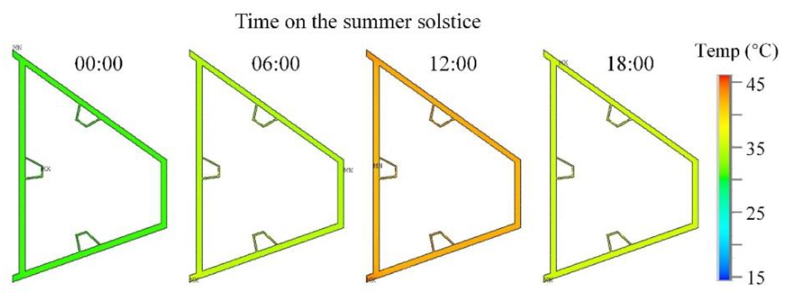
To discuss the environmental effect of the extreme solar state, the change of temperature distribution in the arch cross-section, on the summer solstice, is shown in
Figure 4, with the solution of the FE model.
With the environmental data of different seasons, the corresponding temperature distributions in the cross-section of the arch, girder, and hanger can be calculated, which are shown in
Figure 5. Considering the main structures of the bridge are made of steel, thermal conductivity is good. Therefore, the internal temperature gradient of the structure section is not obvious, and the temperature of the section can be simplified to a unified temperature. Based on this assumption, the sectional average temperature can be considered as the component temperature in the following research on temperature load and effect.
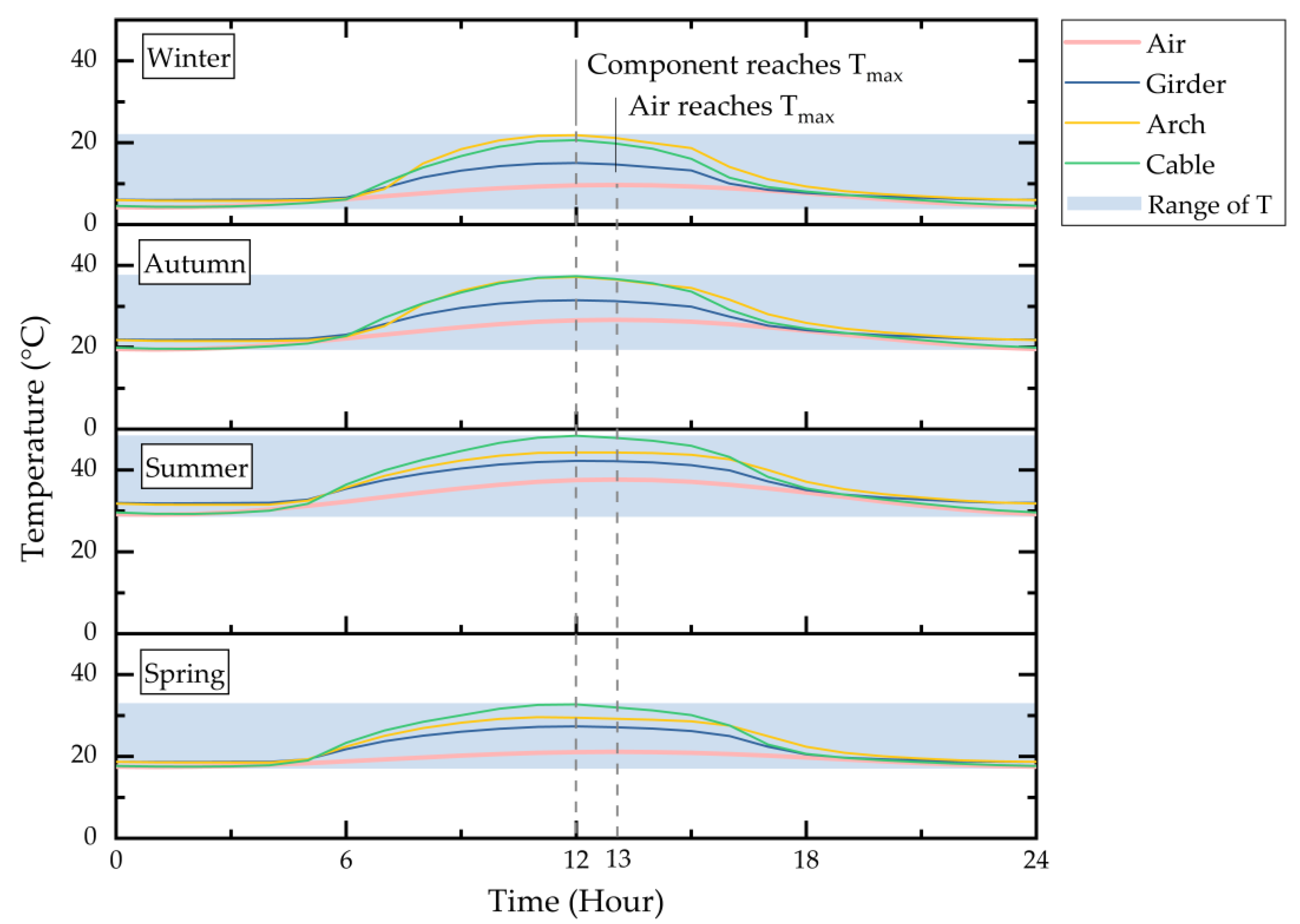
As shown in
Figure 6, there are differences in component temperature in different seasons, and the component temperature after considering radiation characteristics is significantly higher than the ambient temperature. From the point of view of temperature peak, the component temperature is closely related to air temperature. The temperature variation of components in different seasons is also complicated. In spring and summer, the maximum temperature of the hanger is higher than that of the arch and girder, while in autumn and winter, the temperature of the arch is the highest. The reason for this difference may be related to the longitude and latitude of the bridge site, and the direction of the bridge.
Based on the result analysis in
Figure 6, the temperature difference between air and components in day or night and different seasons can be calculated, which is presented in
Table 2. The results show that the temperature difference between different components and the environment is significantly affected by season. The temperature difference is around 5.5 °C between the environment and girder and around 11 °C between the environment and hanger, which is relatively stable. But the temperature between the environment and arch is variable in different seasons, which ranges from about 7.11 °C to 12.36 °C. The temperature difference of bridge components in different seasons is relatively small at night. In the daytime, the difference between the arch and hanger is large, at around 5.5 °C in spring and summer, and the difference between the arch and girder is large, at around 6 °C in autumn and winter.
According to the requirements of Chinese Specification for Design of Highway Bridge and Culverts JTG D60-2015 [
1], the section of steel members does not consider the gradient temperature and only calculates the overall temperature rise and drop of the system. Based on the Chinese Guidelines for Designs of Highway Cable-stayed Bridge JTG/T 3365-01-20 [
2], the temperature difference between the hanger and the steel girder should also be taken into account. The analysis results are compared with the temperature load required by the specifications, and the results show that the values of the overall temperature rise and temperature drop, and the temperature difference of components set by the current code, are conservative. Moreover, the actual temperature field of bridge components is nonuniform and time-dependent, indicating that the temperature model in code is still quite simplified.
3.4. Structural Response with Thermal Load
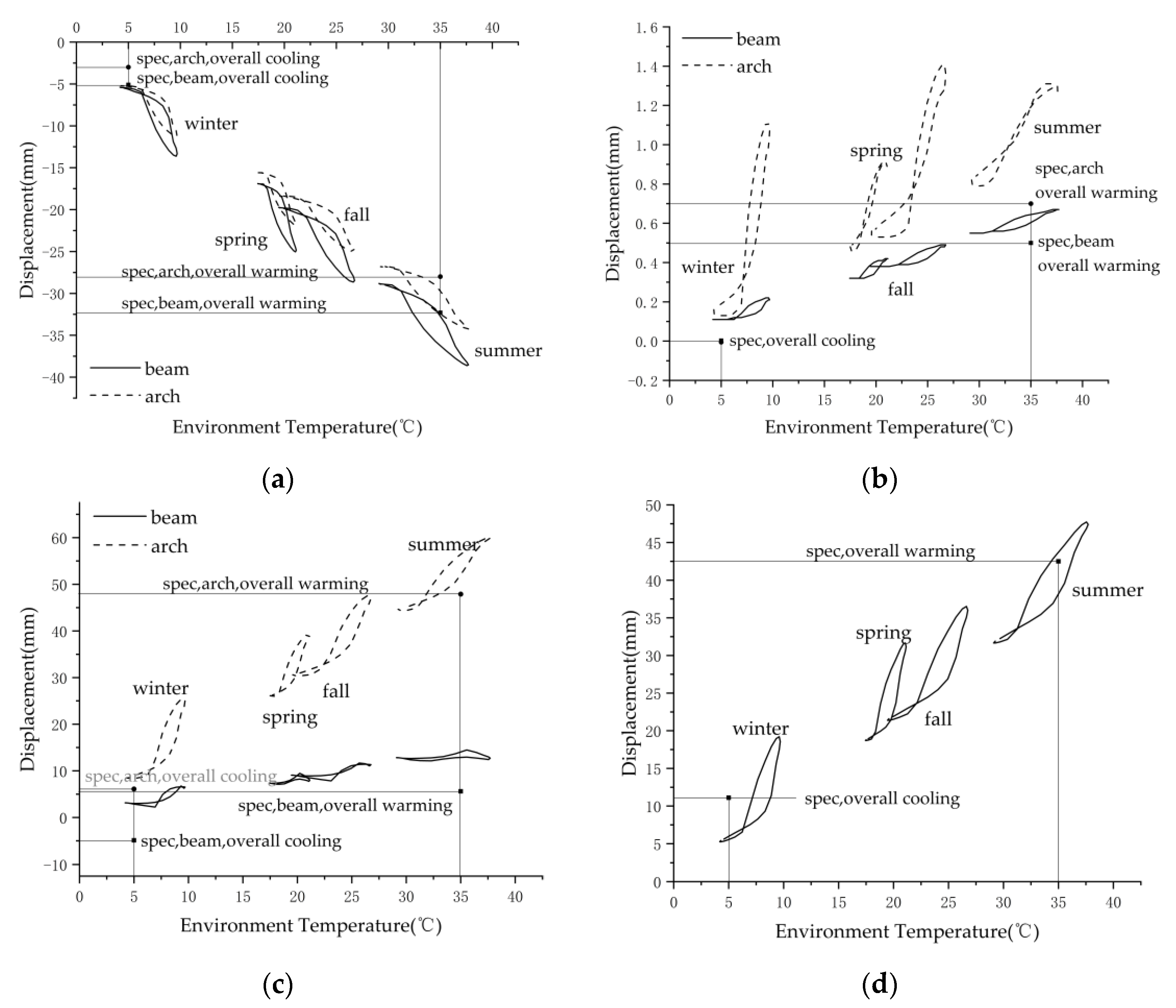
The real temperature fields of the girder, arch, and hanger are applied to the whole structure, and the actual time-varying temperature effect of the structure is calculated. The structural thermal effect caused by the real temperature field is studied through the displacement change of girder and arch and the axial force change of hanger, which is shown in
Figure 7, and is compared with the specifications results.
It can be seen from the figure that the displacement of the structure under the action of temperature is mainly in a transverse and vertical direction. The rate of temperature effect varies greatly among different components, but the seasonal effect is not significant. Due to the temperature difference between 0 and 24 o ‘clock every day, the relation curve between temperature effect and temperature eventually forms a non-closed circle.
Figure 7a shows the relationship between transverse displacement and environmental temperature. The transverse displacement of a girder is slightly larger than that of the arch. When the temperature reaches the highest in summer (38 °C ), the transverse displacement of the girder is close to 40 mm, while of the arch it is only 35 mm.
Figure 7b shows the variation of longitudinal displacement, but the displacement of either the girder or the arch is extremely small.
Figure 7c shows the relationship between vertical displacement and temperature. The vertical displacement of the arch is much larger than that of the girder. Under the action of the highest temperature in summer, the vertical displacement of the girder is only 13 mm, while the arch can reach 60 mm.
Figure 7d shows the girder-arch relative displacement, and its value increases continuously as the temperature increases. In general, the structural displacement and hanger force increase with the increase of temperature, but the variation trend of different components is different. In addition, each sub-figure plots the results calculated according to specification, which are of some constant value and obviously cannot reflect the synchronization with the temperature increasing. From comparison with the specification model related results, it can be seen that the structural thermal effects under the action of the real temperature field exceed the effect level set by specification, which indicates the incompleteness of the specification in the analysis of these complex structures.
5. Conclusions
Current specifications consider the value of temperature load to be constant or gradient. These temperature models are suitable for normal bridges, but may result in inaccurate calculation of thermal effects in complex environments or bridges. To solve this problem, a single-side suspension steel arch bridge is studied, and the simulation process of the refined temperature field and the calculation method of the adverse thermal effects are introduced in detail in this paper. The main conclusions are drawn as follows:
The effect values derived from current specifications are conservative, and the effects under the action of the real temperature field will exceed it. The effect under changing temperature is in linearly positive correlation with temperature, but different components show different variation trends. The temperature difference between different components and the environment is significantly affected by season.
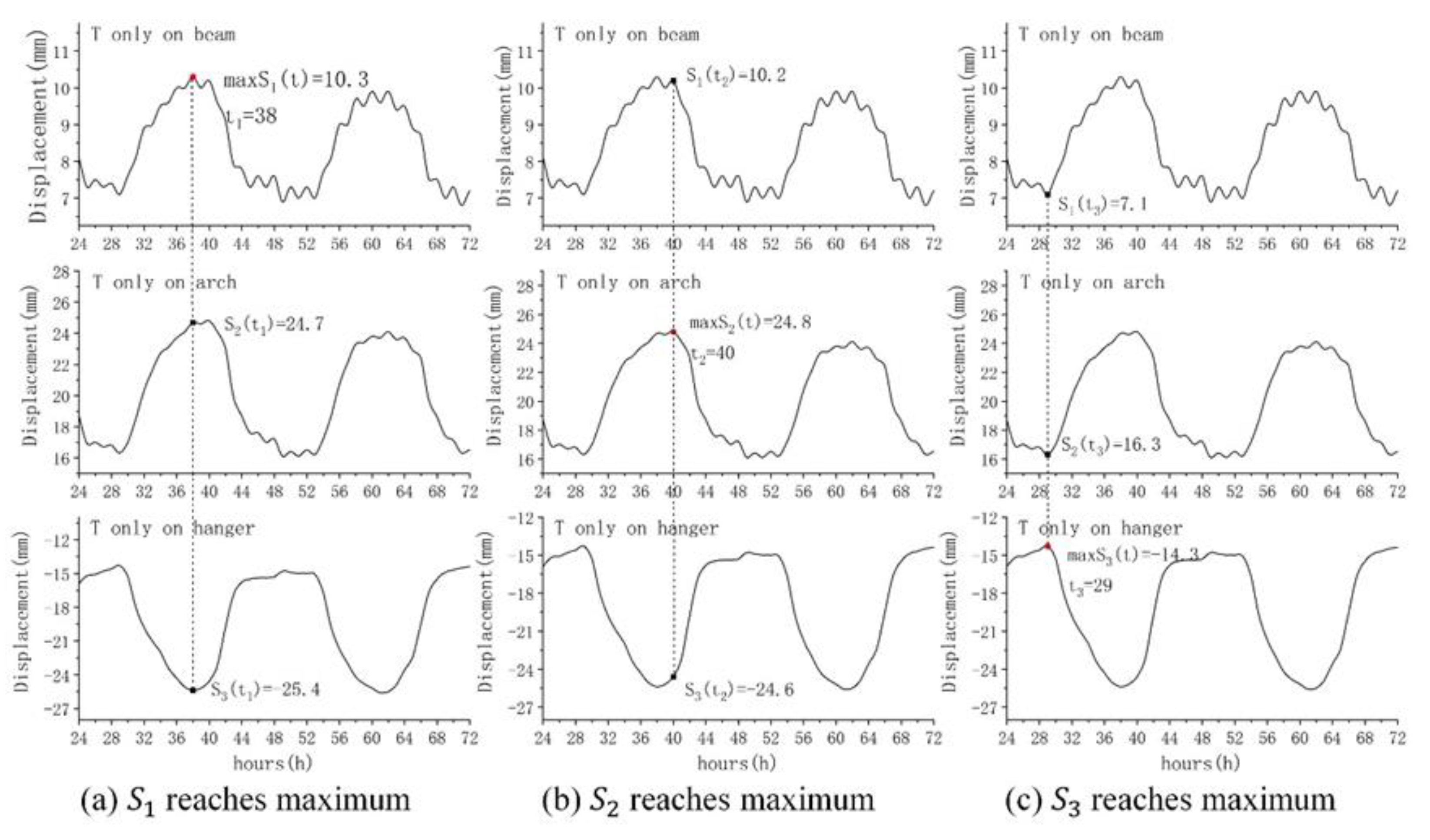
The combination result, using Turkstra’s rule, can reflect the combined effect of the temperature effect of different components, to a certain extent. But the method is not conservative enough since there is a lack of consideration for the adverse case. The JCSS method can consider all the adverse case and has the ability to locate the occurrence time of the maximum, but it is too conservative, due to the stationary binomial process assumption.
With technology advancing, bridge design in future will no longer be limited to conventional structural forms. At the same time, the complexity of environmental systems will increase, due to the impact of global warming. Considering these changing trends, our study proposed an approach or idea to solve practical engineering problems that current design strategy can hardly be specified for particular situations. This will be helpful for determining the direction of follow-up work and attracting the attention of scientists. We suggest using the method proposed in this paper to calculate the refined temperature field, as well as possibly the adverse thermal effect of a complex structure in a specific environment.


