Article

Load-Bearing Performance and Safety Assessment of Grid Pile Foundation

1
Anhui Road & Bridge Engineering Group Co., Ltd., Hefei 230031, China
2
Faculty of Engineering, China University of Geosciences, Wuhan 430074, China
*
Authors to whom correspondence should be addressed.
Sustainability 2022, 14(15), 9477; https://doi.org/10.3390/su14159477
Submission received: 3 June 2022 / Revised: 10 July 2022 / Accepted: 29 July 2022 / Published: 2 August 2022

Abstract

:
Group piles with cushion caps are a common structural form for deep-water bridge foundations. However, their application is limited by the challenges of complex construction, difficult recovery of the supporting large-scale temporary structure, and high engineering expenses. Therefore, we propose a new foundation form—grid pile foundation (GPF)—to improve the sustainability and reliability of foundations. In this study, the finite element software ABAQUS was used to investigate the mechanical properties and dimensional effects of the GPF. Subsequently, the Monte Carlo method was adopted to evaluate the safety under different geological conditions. The results demonstrated that along the depth, the inner frictional resistance of the GPF exhibits an exponential distribution, whereas the outer frictional resistance exhibits an approximate triangular distribution. In addition, the change in pile size has a non-negligible effect on the load-bearing capacity of the GPF. For the same work amount, the smaller pile and side lengths promoted the inner frictional resistance exertion of the GPF. Furthermore, the safety and reliability analysis suggested that the GPF proposed in this study can be used safely under complex geological conditions.

1. Introduction

Underground diaphragm walls (UGDWs) have been widely used in traditional foundation projects, such as foundation pits, water-block curtains, and bridge anchorages, and are gradually being applied in various engineering fields including bridges, high-rise buildings, and anti-seismic liquefaction [1]. A variety of ground improvement methods are in practice these days, including Maheshwari [2], Kumar et al. [3], Rashid et al. [4,5], etc. Group piles with cushion caps are a commonly used foundation form for long-span deep-water bridges. However, the construction of pile group foundations is complicated and requires significant amounts of concrete. In addition, cofferdams, which are used as temporary envelop enclosures during construction, are challenging to recover, thereby increasing the project cost. The aforementioned challenges can be overcome using the lattice (grid) foundation comprising UGDWs. The foundation form in which adjacent UGDWs are connected using rigid joints to form a planar closure with cushion caps is known as the lattice-shaped UGDW foundation. The grid foundation is significantly different from the single-width diaphragm wall foundation in terms of force mechanism and load-bearing performance [6]. Furthermore, it can conserve a significant amount of work in engineering projects compared with conventional pile-group foundations and can withstand complex loads such as horizontal seismic action, wave impact action, and high-speed vehicle braking, thus improving the sustainability and reliability of the entire engineering project [7].
The building block of the grid foundation is the UGDW whose load-bearing performance has been extensively studied. Ou et al. [8] obtained an analytical solution for the lateral displacement of a UGDW with internal support under an eccentric load using the energy method. Lei [9] determined the UGDW-caused ground settlement value using the Mindlin stress solution. Ba et al. [10] demonstrated that the increased UGDW flexibility leads to the redistribution of stresses in the soil and decreases the internal force of the foundation. Li et al. [11] used ABAQUS to simulate a closed UGDW, revealing that the bending and stiffness deformation is maximum at a third of the foundation height under lateral loads. Chen et al. [12] used FLAC 3D to demonstrate that the closed UGDW thickness under a vertical load is proportional to the outer friction and tip resistances, and that the soil core displacement under lateral loads is greater than the wall displacement. However, the construction of UGDW foundations is challenging under certain geological conditions, such as significantly soft silty soil and underwater operation. In addition, the challenges of non-alignment of adjacent wall segments and water leakage may arise. Therefore, a rigid connection of wall segments effectively helps overcome the limitations of water leakage and non-alignment during construction.
The existing grid foundations are predominantly rectangular, and their settlement calculations are primarily based on load-transfer and integral equation methods. Wu et al. [13] calculated the settlement values of simplified rectangular grid foundations using the load-transfer method; their values agreed well with the experimental measurements, thereby establishing the basis for the theoretical calculation for rectangular grid foundations. Wen [14] studied the pile–soil interaction and load-bearing performance of grid foundations; the indoor tests demonstrated that the soil resistance at the corner of the grid foundation end cap is greater than that at the boundary position, and the force at the middle of the boundary is the lowest. Panpan [15] proposed a nonlinear hyperbolic contact model for grid foundations and used numerical simulations to explain why a nonlinear contact model was selected over a linear contact model in grid foundations. In addition, Wu [16] numerically analyzed the “grid effect” and revealed that the ultimate bearing capacity of the grid UGDW does not increase linearly with an increasing number of grids under the same grid size; moreover, the bearing capacity of a single grid significantly weakens, and the stresses between grids overlap. Therefore, it is recommended to adopt the UGDW grid foundations with smaller grid sizes and fewer grids to enhance the bearing performance of the foundation as long as the bearing capacity requirement of the foundation is satisfied.
This study proposes a novel grid foundation with a hollow hexagonal cross-section–grid pile foundation (GPF), to solve the construction and expense challenges encountered while using the pile group foundation with a cushion cap, commonly used in large deep-water bridges. Subsequently, the numerical simulation software, ABAQUS, was used to conduct an in-depth analysis of the settlement, inner and outer frictional resistance, as well as soil pressure distribution laws of the GPF. In addition, the effect of dimensional changes of the GPF on its load-bearing capacity was explored. Finally, a safety assessment of the GPF was performed to support its further application.

2. Construction of the Numerical Model

2.1. Parameters of Numerical Models

In this study, ABAQUS is used to establish two types of numerical models, the single-wall model SWF and the grid pile model GPF. Model schematics are shown in Figure 1. In this paper, two SWF models of different sizes are established, SWF A and SWF B. The SWF A model adopts the dimensions and parameters of the underground diaphragm wall in the field test of Hou [17], and the calculation results of the model are compared with the test results to verify the accuracy of the model established in this paper. The parameters of the SWF B model are the same as those of the model SWF A, only the dimensions are changed, so the accuracy of the SWF B model is also guaranteed. GPF is a grid pile model composed of six SWFs B. The purpose is to compare and analyze the similarities and differences of the force and deformation laws of grid piles surrounded by a single wall and six single walls. In this paper, five GPF models with different sizes are established. The dimensions of all models are shown in Table 1.
In order to compare the in situ loading test results of a UGDW of Hou [17], the material parameters of the numerical model are the same as in the literature [17]. The detailed physical parameters are shown in Table 2. The friction coefficient µ between the pile and soil is selected as 0.23, which is based on the recommended value of the friction coefficient between the pile foundation and the soil in the Technical Code for Building Pile Foundations (JGJ94-2008) [18] and combined with the literature [17].
In ABAQUS, the pile is assumed to be a linear elastic material, and the soil adopts the Mohr-Coulomb elastic-plastic model. The soil is divided into two layers: Soil layers 1 and 2. The tangential contact between the pile and soil was calculated using a hard contact–penalty calculation model, whereas the normal contact was a “hard” form to limit the penetration of the pile into the soil. The lateral pressure coefficient K0 between the pile and soil is calculated from the internal friction angle according to Equation (1).
k 0 = 1 sin ( φ )
The C3D8R three-dimensional stress element is used for the pile and soil, respectively. According to the division method of the sweep, the GPF ① model has a total of 65,419 units.

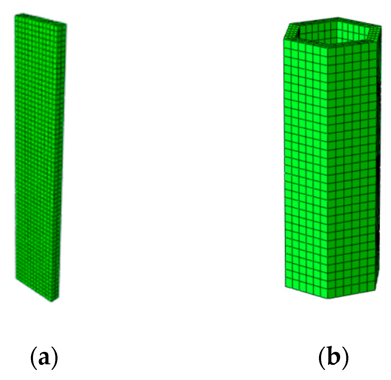
2.2. Numerical Model for SWF

The settlement curve of SWF A is shown in Figure 2. A distinct inflection point is observed in the settlement curve, and the position of the inflection point is generally considered the ultimate load-bearing capacity of the foundation. Before the SWF reaches the ultimate load-bearing capacity, the load has a roughly linear relationship with the settlement; in addition, the settlement increases rapidly after the ultimate load-bearing capacity is reached. Numerical simulation calculations indicate that the ultimate load-bearing capacity of SWF is 14.8 MN, wherein the settlement is 32.9 mm.
The settlement curve derived from the field test by Hou [17] is shown in Figure 2. The settlement curve indicates that the ultimate load-bearing capacity of the single-width UGDW is 14 MN (corresponding to a settlement value of 28 mm), and the settlement exhibits a steep-drop pattern. Before reaching the ultimate load-bearing capacity, the settlement curve scales linearly. Subsequently, we compared the settlement curve obtained from the numerical model calculation with that of the field test data of Hou [17] (Figure 2), indicating a high degree of agreement and demonstrating the accuracy of the established numerical model for SWF.

2.3. Numerical Model for GPF

The dimensions of SWF A were changed to build SWF B. Subsequently, six SWFs B were used to build the GPF model ①. Then, we loaded both models to 60 MN and obtained the stress nephogram, as shown in Figure 3. S33 is the stress in the vertical direction. The stress distribution of SWF B and GPF under identical loads reveals that the soil pressure on both sides of the SWF is higher, whereas the pile core soil of the GPF exhibits high stress only near the pile end. Therefore, the area enclosed by six SWFs considerably decreases the stresses in the soil, particularly in the pile core soil.

3. Numerical Calculation and Analysis of GPF

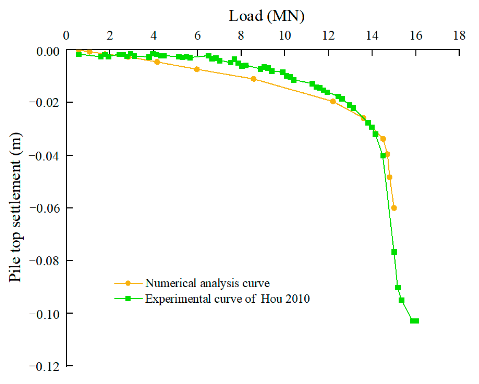
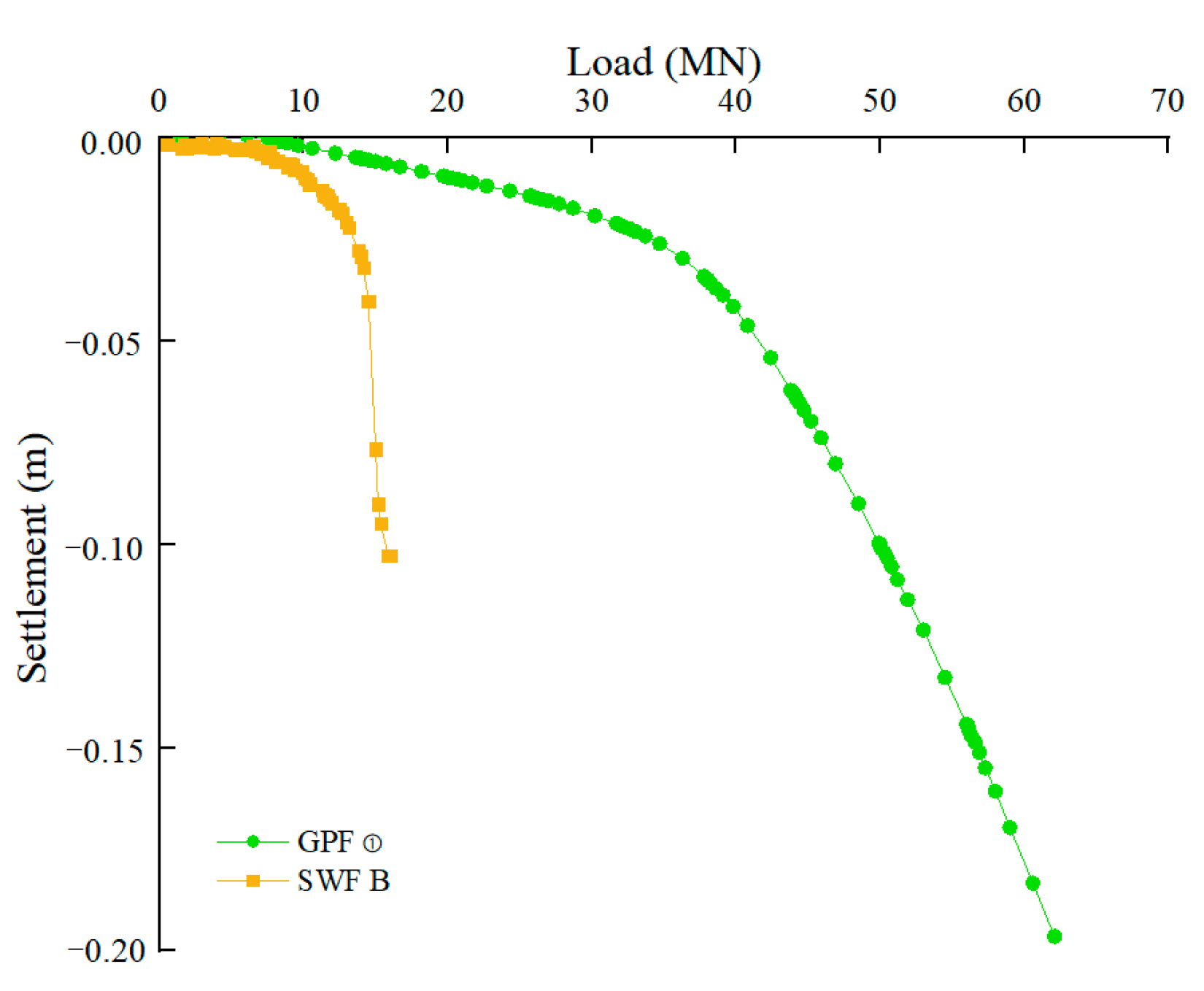
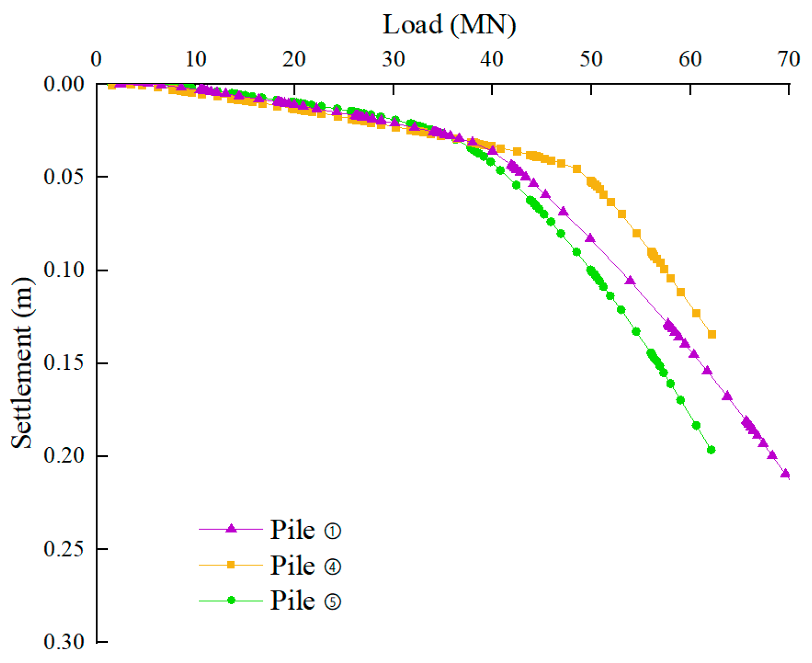
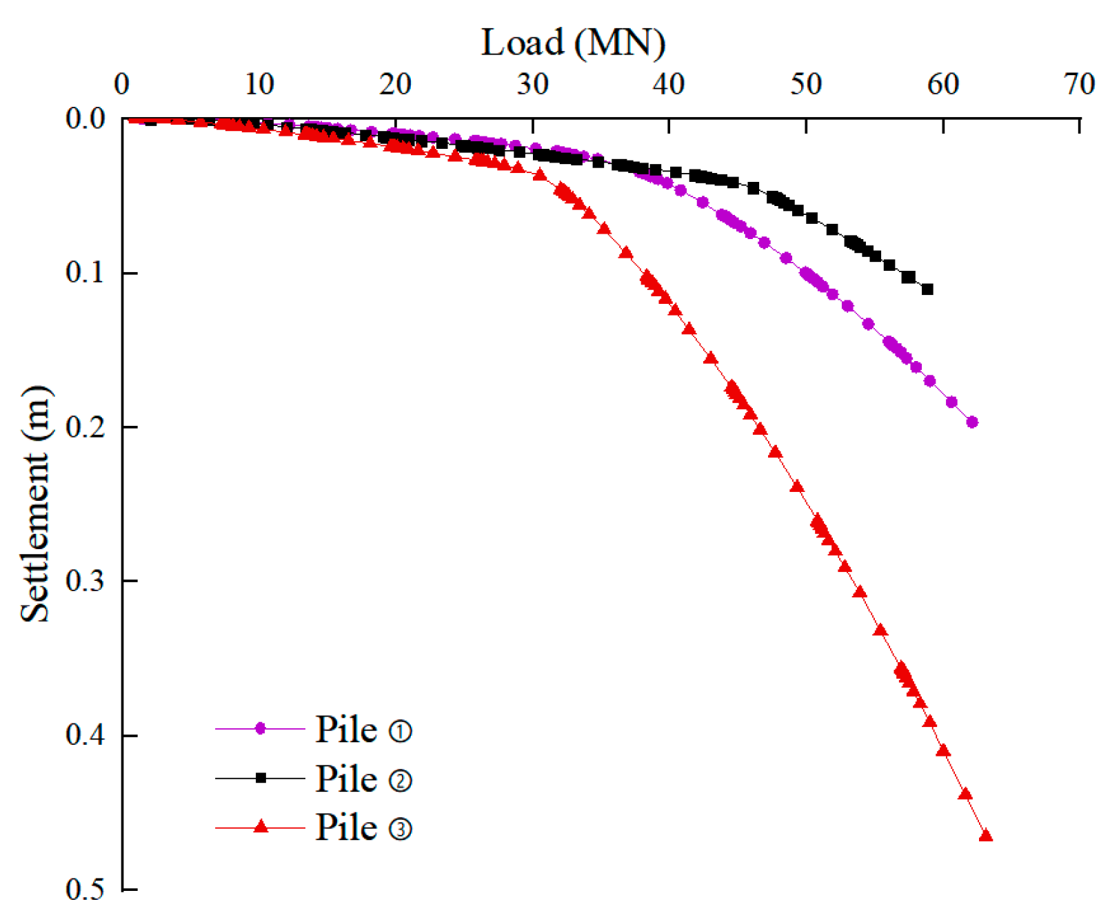
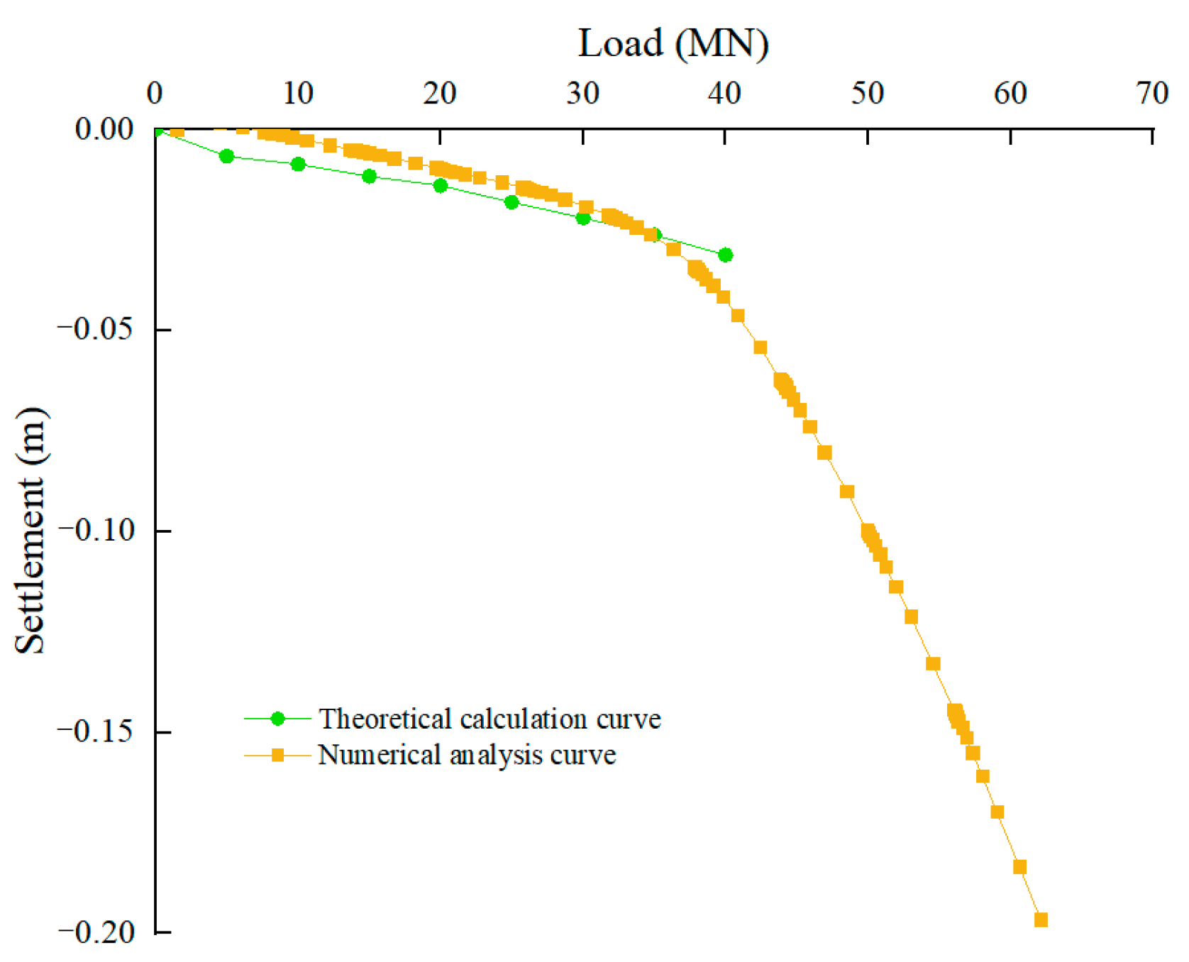
3.1. Settlement Curve Analysis

Figure 4 shows that the settlement curve of the GPF changes more gradually. According to the Code for Design of Building Foundation (GB50007-2001) [19], when the settlement curve has no distinct inflection point, the ultimate load-bearing capacity is the corresponding load-bearing capacity when the foundation settlement value reaches 0.04 m. Therefore, the ultimate load-bearing capacity of the GPF is 45.7 MN, which is greater than that of an SWF of an identical size by a factor of 3.11. Although a GPF comprises six SWFs, the load-bearing capacity of the GPF is not greater than that of the SWF by a factor of six. In other words, the load-bearing capacity of the GPF is not equal to the sum of the load-bearing capacity of all the SWFs.
The vertical load-bearing capacity of a GPF is primarily composed of three parts, outer frictional resistance, inner frictional resistance, and tip resistance. During the beginning of loading, the outer frictional resistance is gradually exerted; with increasing load, the relative displacement between the pile body and outer soil body occurs, leading to the gradual exertion of the outer frictional resistance. Subsequently, relative displacement occurs between the pile core soil and pile body, at which point the inner frictional resistance and end resistance are exerted until both their limits are reached. Then, the pile settles faster and cannot maintain stability for long periods, and the load-bearing capacity at this time is the ultimate load-bearing capacity. This phenomenon of the load-bearing capacity of the GPF being less than the sum of the load-bearing capacities of all SWFs is known as the “group wall effect”, which is similar to the “group pile effect” of the pile group foundation that reduces the load-bearing capacity of the pile group [20].

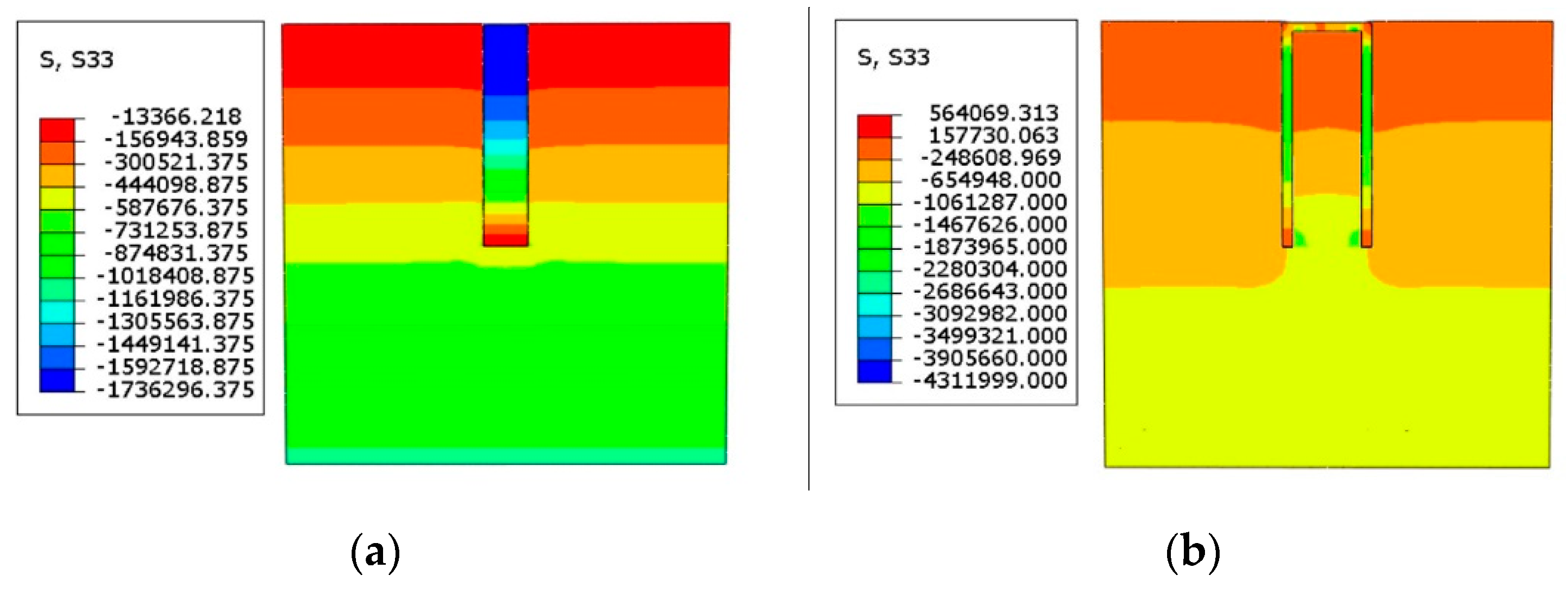
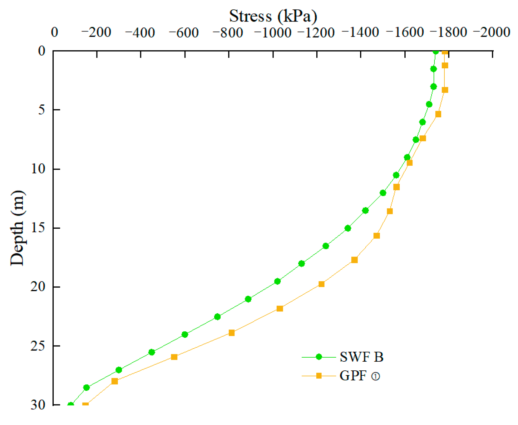
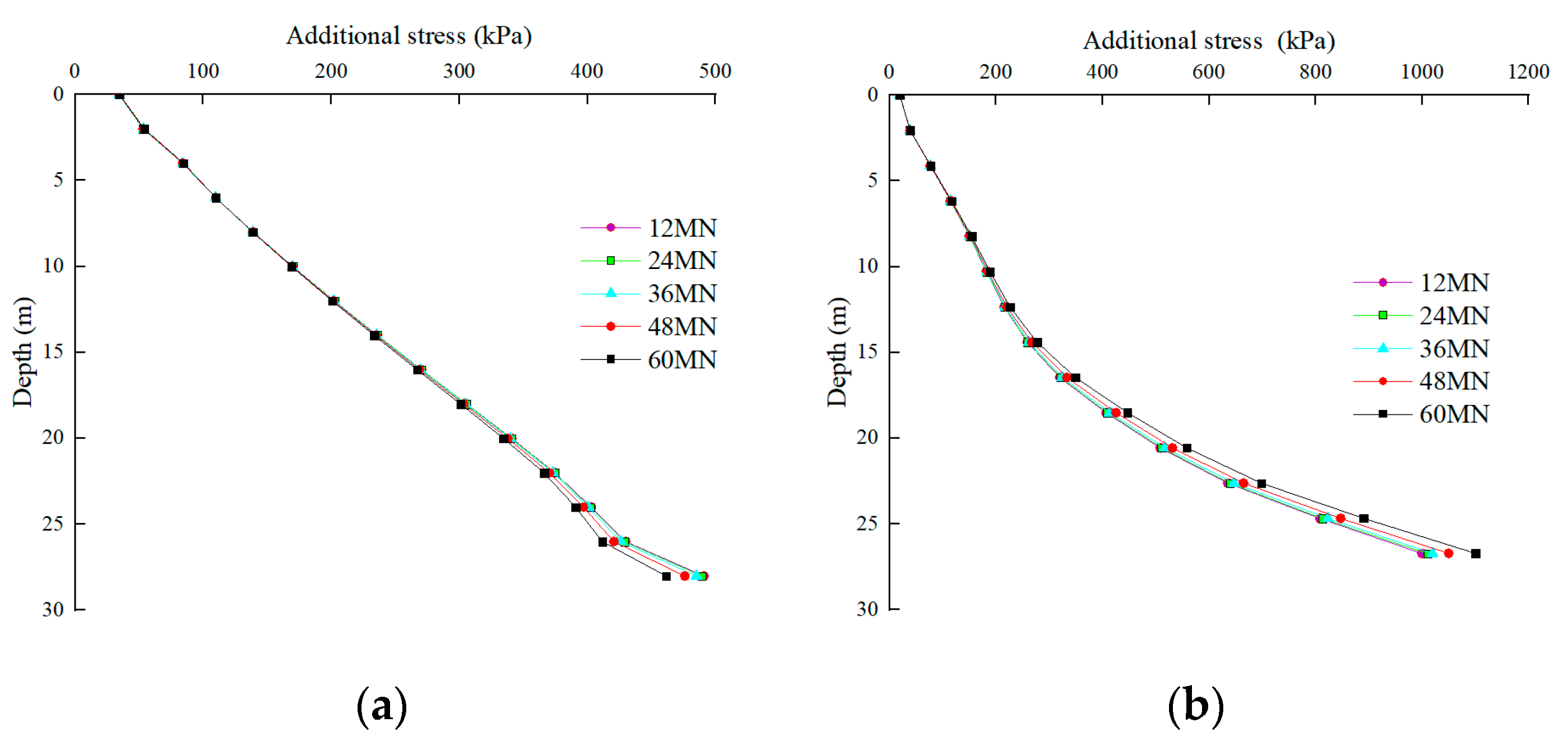
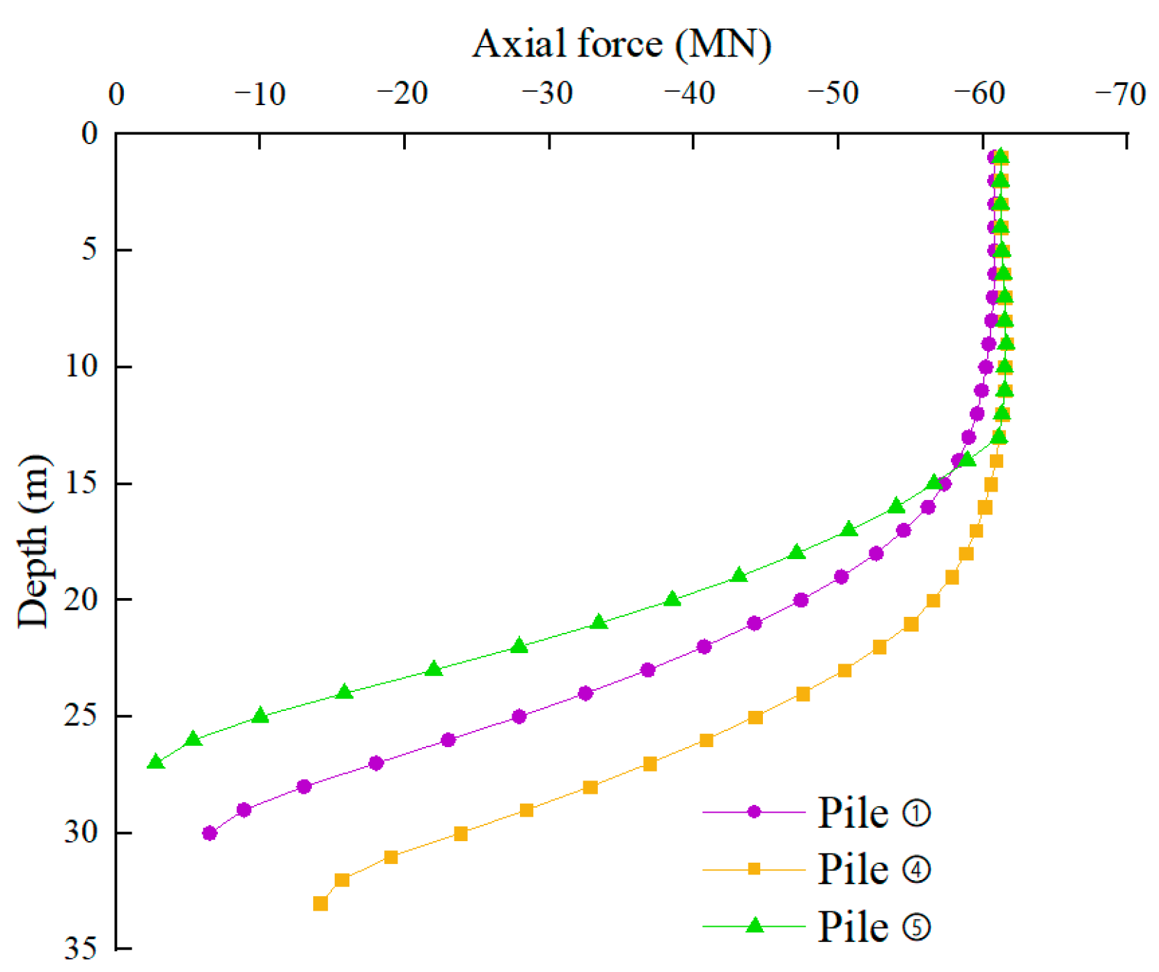
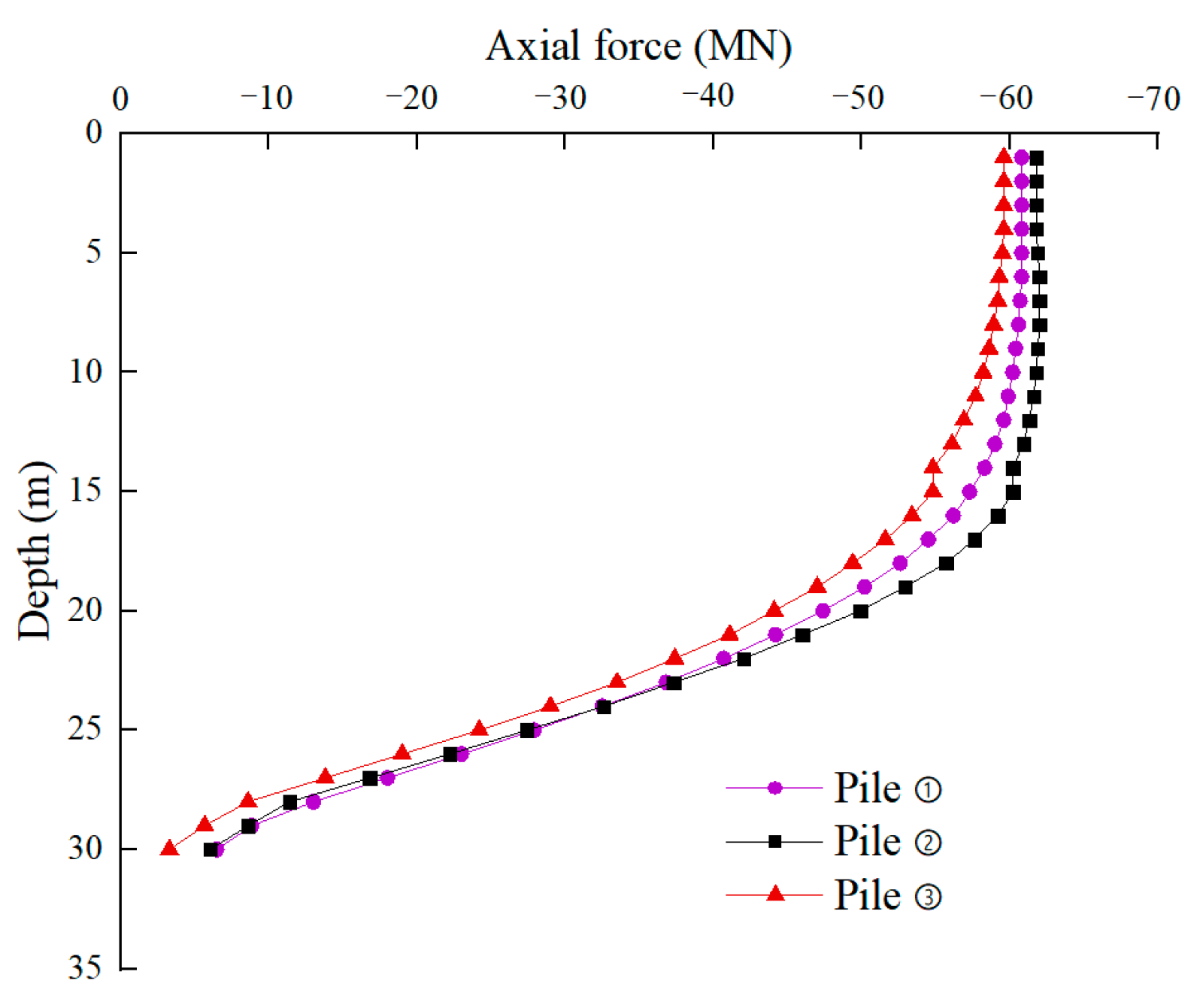
3.2. Stress Analysis of Pile and Soil

Figure 5 shows that the stress value of the GPF is slightly higher than that of the SWF when approaching their respective load ultimate bearing capacity. The pile stress curves of the SWF and GPF are of similar shapes. In addition, the stress decreases from approximately −1800 kPa at the top of the pile to approximately −200 kPa at the bottom; moreover, the stress in the upper third of the pile is higher and decreases gradually downward; in contrast, the stress in the lower third of the pile rapidly decreases downward. Therefore, the strength of the upper third of the pile should be strengthened while designing the pile foundation.
Figure 6 shows that the vertical stress in the soil increases with increasing depth. With increasing pile top load, the increase in the vertical stress in the pile core soil is slightly higher than that of the soil outside the pile. In addition, the stress variation of the pile core soil is in the lower two-thirds region of the soil core, whereas the stress variation of the soil outside the pile is in the lower one-third region of the pile body. This is because of the following: The interaction between the outer part of the pile body and the soil body distributes the load applied to the soil body at a certain diffusion angle, which is the same as the soil stress distribution law of solid piles. After the pile core soil is stressed, the lower portion of the soil core is continuously squeezed inward owing to the squeezing effect, consequently resulting in the soil core’s tendency to move toward the upper portion of the pile; however, the cushion cap at the pile top restricts the upward movement of the soil core, resulting in increasing the stress in the soil core to greater than that in the outer soil body. With increasing load, the pile core soil is affected by squeezing in an increasing upward range, thereby resulting in the continuous bottom-to-top expansion of the pile core soil stress.
Numerical calculations indicate that the inner frictional resistance accounts for a significant proportion of the pile resistance at the later loading stage, indicating its significant contribution to the load-bearing performance. When the ultimate load is reached, the load-bearing capacity of the soil core remains not fully exerted. Therefore, the continuous optimization of the GPF dimensions to determine the optimal cross-section size can enable earlier and fuller exertion of the inner frictional resistance in the load-bearing phase.

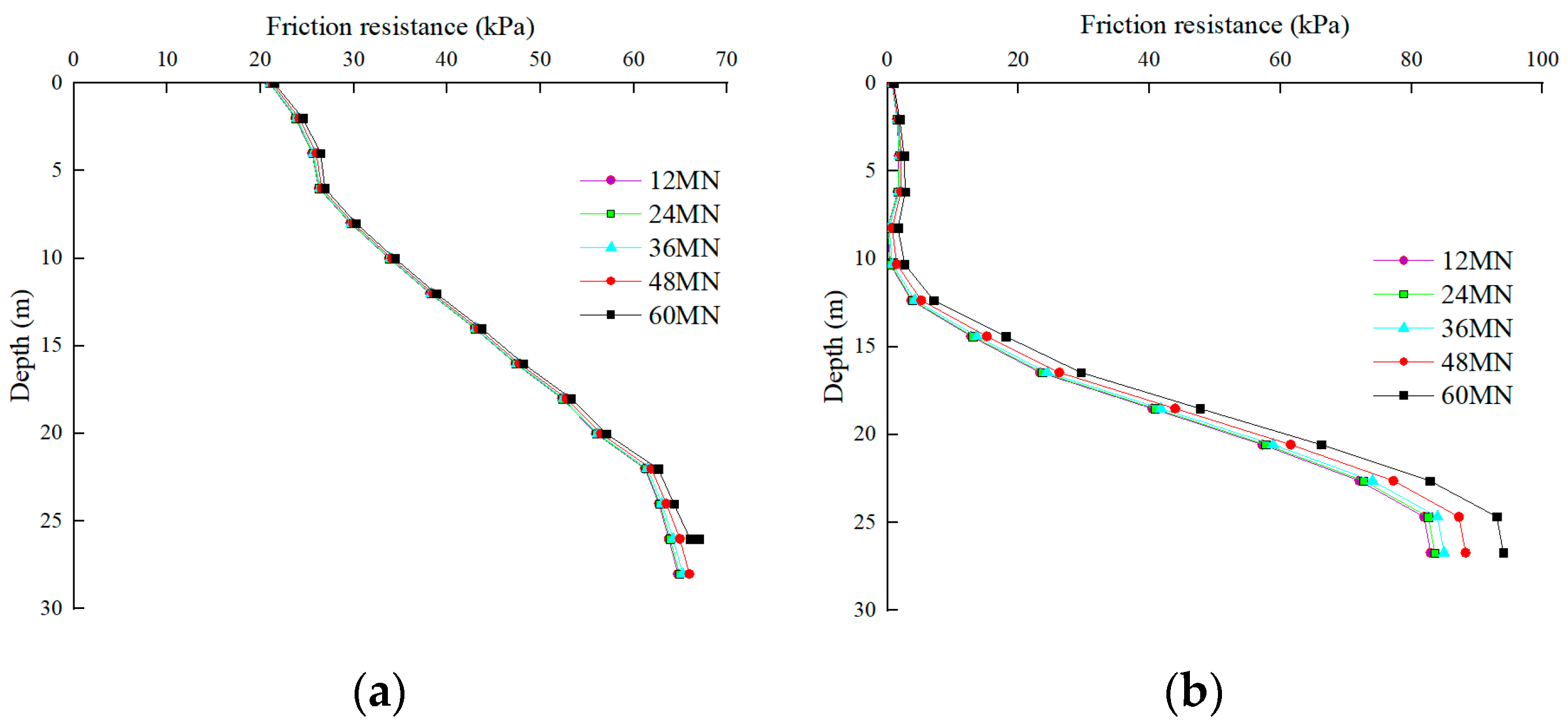
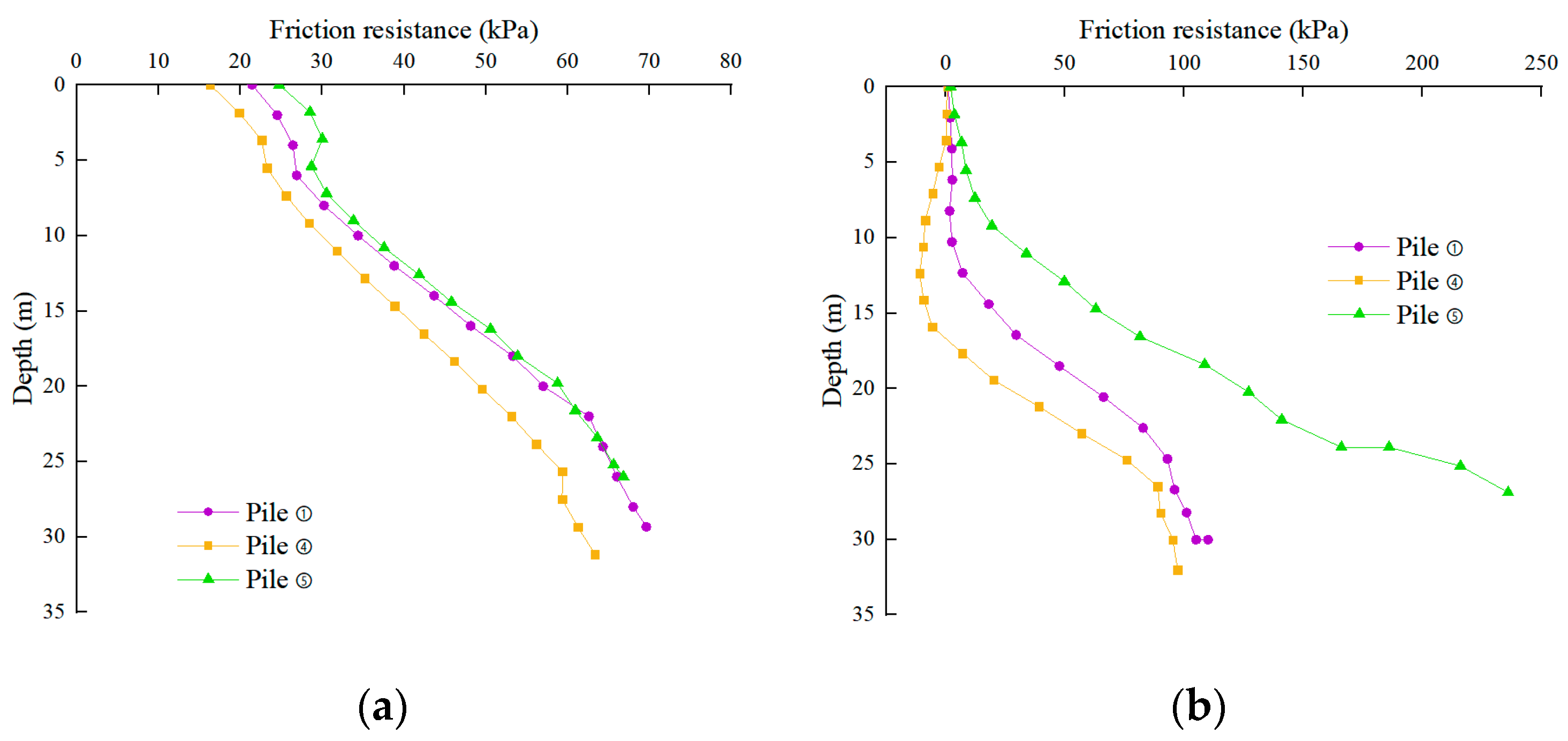
3.3. Analysis of Lateral Frictional Resistance of Pile

Figure 7 shows the variation curves of the outer and inner frictional resistance of the GPF with an increasing load. A comparison of Figure 7a,b reveals that the inner frictional resistance contributed by the soil core in the pre-loading period is significantly lower than the outer frictional resistance of the pile, whereas the inner frictional resistance is less than the outer frictional resistance. According to the aforementioned mechanism of pile core soil stress generation, the core soil is confined within the pile and sinks along with the pile body. The low relative displacement of the pile core soil and the pile body significantly decreases the inner pile soil frictional resistance. With an increasing load, the soil at the bottom of the pile is gradually extruded from the bottom into the pile, thereby resulting in the relative displacement of the lower portion of the soil core and pile body. Therefore, the inner frictional resistance is predominantly concentrated at the bottom of the pile and expands upward continuously with an increasing load. The inner frictional resistance is exponentially distributed along the pile body, and the percentage of total frictional resistance increases with increasing load, which is consistent with the observations of Liu [21].

4. Impact of Change in GPF Size on Its Load-Bearing Performance

To study the impact of the side and pile lengths of the GPF on its load-bearing performance, five GPF models with different sizes were established, as shown in Table 2. Then, we calculated the five GPF models separately and analyzed the effect of pile and side length variations on its load-bearing performance based on the calculation results.

4.1. Impact of Pile Length on Load-Bearing Performance

The settlement curves of piles ①, ④, and ⑤ shown in Figure 8 characterize the impact of pile length on the ultimate load-bearing capacity and settlement value of the GPF. According to the Code for Design of Building Foundation [19], the maximum settlement value of the foundation must not exceed 0.04 m. The settlement curves of piles ①, ④, and ⑤ in Figure 8 have no inflection point before the settlement value reaches 0.04 m, and the corresponding load-bearing capacity values are 40.2, 49.6, and 38.72 MN, respectively, which meets the design requirements of the settlement value. Therefore, increasing the pile length can enhance the load-bearing capacity of the GPF. However, this is effort-intensive, consequently increasing the engineering cost.
The axial force curves of piles ①, ④, and ⑤ shown in Figure 9 characterize the impact of pile length variation on the axial force. Pile ① is set as the reference pile. Comparing the axial force of piles ④ and ⑤ indicates that the pile length ④ increases compared with that of pile ①, and the area with the higher axial force in the upper part of pile ④ is significantly greater than that of pile ①. In addition, the tip axial force of pile ④ is greater than that of pile ①, indicating an increase in tip resistance. However, compared with that of pile ①, the length of pile ⑤ decreases, and the area with the higher axial force at the upper portion of pile ⑤ is significantly smaller than that of pile ①, with the axial force in the pile tip tending to zero. With increasing pile length, the influence range of the load extends downward. Figure 5 and Figure 7 show that the variations of the stress and frictional resistance of the upper part of the pile are less along the depth, indicating that the frictional resistance of the GPF is not exerted in the upper part of the pile. Therefore, appropriately reducing the pile length can increase the frictional resistance and decrease the tip resistance.
The frictional resistance distribution of piles ①, ④, and ⑤ in Figure 10 characterizes the impact of pile length on the inner and outer frictional resistance of the GPF. Figure 10a shows that the outer frictional resistance of the GPF has a trapezoidal distribution, and the outer frictional resistance increases approximately linearly along the pile body, with small variations in the three curves. Therefore, the impact of the outer frictional resistance caused by the varying pile length is significantly low and can be neglected. Figure 10b shows the inner frictional resistance of piles ①, ④, and ⑤. The distribution of the inner frictional resistance of piles ④ and ⑤ is virtually identical (exponential distribution). The inner frictional resistance of pile ⑤ is significantly higher than those of piles ① and ④, and its distribution along the length of the pile is comparable to that of a triangle. The inner frictional resistance in the middle and upper portions of pile ⑤ is also significantly higher than those in piles ① and ④. Therefore, pile length variations significantly impact inner frictional resistance. Furthermore, an increase in pile length inhibits the exertion of inner frictional resistance in the upper part of the pile and negligibly affects the outer frictional resistance.

4.2. Impact of Pile Side Length on Load-Bearing Performance

Figure 11 shows the settlement curves of piles ①, ②, and ③. The inflection points in the curves indicate that the ultimate load-bearing capacities of piles ③, ①, and ② are 30, 40, and 46 MN, respectively. Therefore, increasing the side length can improve the ultimate load-bearing capacity of the foundation. However, an increasing side length decreases the ultimate load-bearing capacity improvement rate. In this case, an increase in the load-bearing capacity only arises from the increase in outer frictional resistance and pile tip resistance.
The axial force curves of piles ①, ②, and ③ shown in Figure 12 characterize the impact of pile side length on the axial force. The side length of pile ② is larger than that of pile ①, and the axial force at the upper part of pile ② increases, whereas the axial force at the lower part of the pile slightly changes. In addition, the side length of pile ③ is smaller than that of pile ①, and the overall reduction of axial force causes a reduction in the axial force at the tip of the pile, subsequently tending to zero.
Figure 13a shows the distribution of the outer friction resistance of piles ①, ②, and ③. We inferred that the outer frictional resistance is not significantly affected by the change in pile side length. Figure 13b shows the distribution of the inner frictional resistance. The increase in the side lengths of piles ① and ② does not significantly change the frictional resistance. However, a decrease in the pile ③ side length and the relative decrease in the soil core diameter causes a larger inner frictional resistance posed by the soil core in the middle and lower portions of the pile. When the side length is small, the small diameter of the soil core causes a significant squeezing effect at the bottom of the pile, resulting in a gradual increase in the inner frictional resistance and its exertion toward the pile tip. Therefore, the inner frictional resistance contributes more to the increase in load-bearing capacity. The diameter of the soil core increases continuously with increasing side length, consequently resulting in a moderately weaker squeezing effect of the pile. Hence, the increase rate in the inner frictional resistance provided by the soil core decreases.
The above analyses indicate that the variations in the pile and side lengths have less effect on the outer frictional resistance. However, decreasing the pile and side lengths can enhance the exertion of the inner frictional resistance. In addition, decreasing the tip resistance can improve the load-bearing performance of the GPF.

5. Simplification Algorithm and Safety Evaluation Method for GPF Settlement

5.1. Simplification Algorithm for GPF Settlement Based on Mindlin Stress Solution

Definite theoretical research on the settlement calculation method of the GPF has not been reported yet. Therefore, we calculated the additional stresses in the foundation based on the settlement calculation method of tubular piles, which is similar to the GPF structure, based on the semi-infinite space mechanics model established by Mindlin’s stress solution [22]. In addition, we derived the foundation settlement values using the layerwise summation method.
According to Zhu and Wang [23,24], the upper load on the silo pile is shared by the tip, outer frictional, and inner frictional resistance; in addition, additional stresses are generated in the foundation when the three resistances are exerted. Liu [25] calculated the additional stresses in the foundation according to Mindlin’s method of deriving stresses, modified the integration area, and set the circular bottom surface of the tubular pile as well as the inner and outer sides as the integration areas of the end, inner frictional, and outer frictional resistances, respectively, to obtain the additional stresses in the foundation at different depths, subsequently deriving the total settlement using the splitting summation method. In this study, the method available in the literature [25] is adopted, and the resistances in the upper part of the GPF are classified as the tip, inner frictional, and outer frictional resistances. However, the additional stress integration region of the GPF changes, and the bottom surface is a positive hexagonal ring. Furthermore, the inner and outer sides are composed of six rectangles. Therefore, we determined the additional stresses generated in the foundation by end resistance, inner side frictional resistance, and outer side frictional resistance based on the calculation method of Mindlin’s stress solution and superimpose them, as shown in Equation (2).
S = ψ p P p L 2 j = 1 m i = 1 n j Δ h j , i E s j , i k = 1 n [ α I P A , k + β I P i , k + ( 1 α β ) I P s , k ] ,
where S is the final deformation amount of the foundation (mm), ψ p is the empirical coefficient of settlement calculation (0.5), E s j , i is the compression modulus of the ith layer of soil on the foundation floor (MPa), and α and β are the load distribution coefficients of the outer and inner frictional resistances, respectively.
I P A , k = L 2 P p σ z , P A ,
I P I , k = L 2 P p σ z , P i ,
I P s , k = L 2 P p σ z , P s ,
where I P A , k ,   I P i , k , and   I P s , k are the respective stress influence coefficients generated by each part of the load for the settlement calculation.
The total settlement amount was calculated using Equation (2). In addition, the settlement curve generated using the same soil parameters as those listed in Table 1 is shown in Figure 14. Moreover, the settlement curve obtained from the numerical calculation includes the failure stage. Because the Mindlin stress solution used in Equation (2) is based on the elastic semi-infinite space, the settlement curve obtained only characterizes the elastic stage.
Numerical calculation results indicate that the GPF settlement curve has a distinct inflection point. When the inflection point is reached, the settlement value rapidly increases. Before reaching the inflection point, the theoretically calculated settlement value is slightly higher than the numerically calculated value, and the two curves exhibit a similar variation law and are in good agreement with each other. Therefore, Equation (2) is applicable to calculate the settlement of the GPF, with conservative prediction results.

5.2. Monte Carlo Method-Based Settlement Reliability Analysis of GPF

In Section 4.1, we assumed that the foundation soil is homogeneous for the GPF settlement value calculation. However, diverse soil layers and complex geological conditions are present in the actual projects. Therefore, it is required to determine whether the pile foundation fails under complex geological conditions. Herein, we adopted a simplified algorithm for the Monte Carlo-based settlement evaluation of the GPF, focusing on the effects of different geological conditions on the values tested to establish a more intuitive and comprehensive safety index of the GPF.
The Monte Carlo method is based on the concept of generating numerous subsamples by random sampling based on the distribution patterns of random variables [26,27,28]. We set the number of subsamples to N and introduced the subsample values to the structure work function to determine the failure and count the number of failures ( n f ). According to the law of large numbers, the failure probability ( P r ), which can be unbiasedly estimated via the failure frequency, is expressed as follows [29]:
P r = n f N .
Let the structure work function be as follows:
Z = g X .
Then, the structural failure probability can be expressed as follows:
P r = P [ g X < 0 ] .
The reliability β can be expressed as follows:
β = ϕ 1 1 P r ,
where ϕ 1 ( x ) denotes the inverse function of a certain parameter.
The Technical Code for Building Pile Foundations [18] contains clear provisions for the settlement values of pile foundations. Generally, the settlement value of the pile foundation should be controlled to within 0.04 m. Therefore, pile foundations with settlement values that exceed this value can be considered supplementary to the required settlement to be used (i.e., load-bearing failure). We set Equation (2) as the work function. In addition, it is suggested that the random variables include the elasticity modulus, E, Poisson’s ratio, ν , and pile top load, P [30,31]. The statistics of the random variables obtained based on the GPF dimensions described in this study are listed in Table 3.
The sample size, N, in this study is 1 million to ensure the accuracy of the estimated reliability [32,33,34]. The calculated failure probability ( P r ) and reliability ( β ) are 8.7 × 10⁻⁵ and 3.754, respectively. The reliability of this study is greater than the threshold value (3.5) specified in the Specifications of the National Transportation Association of the USA [35]. Therefore, the GPF proposed in this study can be safely used under complex geological conditions.

6. Conclusions

(1)
Under identical grid sizes, the soil stress and frictional resistance of the GPF change less with the increasing load, thereby resulting in significant changes in the inner frictional resistance in the lower portion of the pile.
(2)
Along the depth, the inner frictional resistance of the GPF exhibits an exponential distribution pattern, whereas the outer frictional resistance shows an approximately triangular or trapezoidal distribution pattern.
(3)
The stress in the upper third of the pile length is higher. Therefore, the strength of the upper third of the pile should be strengthened during pile foundation designing.
(4)
The changes in the pile and side lengths have a small effect on the outer frictional resistance, and their reductions can improve the exertion of inner frictional resistance and reduce the tip resistance. Therefore, the GPF load-bearing performance can be enhanced.
(5)
The safety and reliability analyses indicate that the GPF proposed in this study can be safely used under complex geological conditions.

Author Contributions

Conceptualization, R.T.; Formal analysis, R.T.; Funding acquisition, Y.J.; Investigation, Y.W.; Methodology, W.Z.; Project administration, Y.J.; Software, Y.W.; Supervision, W.Z.; Writing—review & editing, Y.J. All authors have read and agreed to the published version of the manuscript.

Funding

This research was funded by the state key international cooperation research project of the National Natural Science Foundation of China (Grant No. 41920104007).

Institutional Review Board Statement

Not applicable.

Informed Consent Statement

Not applicable.

Data Availability Statement

Not applicable.

Conflicts of Interest

The authors declare no conflict of interest.

References

  1. Wu, J.; Cheng, Q.; Wen, H. Overview of the variety of diaphragm wall foundation developed in Japan in recent years. Ind. Constr. 2013, 43, 1. [Google Scholar]
  2. Maheshwari, P. Analysis of combined footings on extensible geosyntheticstone column improved ground. J. Civ. Eng. Sci. Technol. 2017, 8, 57–71. [Google Scholar] [CrossRef]
  3. Kumar, P.; Kumar, M.; Chandaluri, V.K.; Sawant, V.A. Uplift capacity of single and group of granular anchor pile system. J. Civ. Eng. Sci. Technol. 2018, 9, 34–40. [Google Scholar] [CrossRef] [Green Version]
  4. A Rashid, A.S.; Black, J.; Kueh, A.B.H.; Mohamad, H.; Md Noor, N. Bearing capacity charts of soft soil reinforced by deep mixing. Inst. Civ. Eng. 2017, 170, 12–25. [Google Scholar] [CrossRef]
  5. A Rashid, A.S.; Kueh, A.B.H.; Mohamad, H. Behaviour of soft soil improved by floating soil–cement columns. Inst. Civ. Eng. 2018, 18, 95–116. [Google Scholar] [CrossRef]
  6. Wu, J.; Cheng, Q.; Wen, H.; Cao, J.-L. Vertical bearing behaviors of lattice shaped diaphragm walls and group piles as bridge foundations in soft soils. Chin. J. Geotech. Eng. 2014, 36, 1733–1744. [Google Scholar]
  7. Wu, J.; Cheng, Q.; Wen, H.; Li, Y.; Zhang, J.; Wang, L. Comparison on the Horizontal Behaviors of Lattice-Shaped Diaphragm Wall and Pile Group under Static and Seismic Loads. Shock Vib. 2016, 2016, 1289375. [Google Scholar] [CrossRef] [Green Version]
  8. Ou, Q.; Zhang, L.; Zhao, M.; Wang, Y. Lateral Displacement and Internal Force in Diaphragm Walls Based on Principle of Minimum Potential Energy. Int. J. Geomech. 2019, 19, 04019055. [Google Scholar] [CrossRef]
  9. Lei, G.H.; Sun, H.S.; Ng, C.W.W. An Approximate Analytical Solution for Calculating Ground Surface Settlements Due to Diaphragm Walling. Comput. Geotech 2014, 61, 108–115. [Google Scholar] [CrossRef]
  10. Yajnheswaran, B.; Akshay, P.R.; Rajasekaran, C.; Rao, S. Effect of stiffness on performance of diaphragm wall. Procedia Eng. 2015, 116, 343–349. [Google Scholar]
  11. Liu, L.; Dai, G.; Gong, W. Numerical analysis about bearing characteristics of closed diaphragm wall under horizontal load. In Proceedings of the International Symposium on Innovation and Sustainability of Structures in Civil Engineering (ISISS 2011), Xiamen, China, 28–30 October 2011. [Google Scholar]
  12. Chen, Q.; Wu, J.; Song, Z.; Wen, H. The behavior of a rectangular closed diaphragm wall when used as a bridge foundation. Front. Struct. Civ. Eng. 2012, 6, 398–420. [Google Scholar]
  13. Wu, J.; Chen, Q.; Wen, H.; Wang, L.; Li, Y.; Zhang, J. A load transfer approach to rectangular closed diaphragm walls. Inst. Civ. Eng. 2016, 169, 509–526. [Google Scholar] [CrossRef]
  14. Wen, H.; Chen, Q.; Meng, F.; Chen, X. Diaphragm wall-soil-cap interaction in rectangular-close diaphragm-wall bridge foundations. Front. Archit. Civ. Eng. 2009, 3, 93–100. [Google Scholar] [CrossRef]
  15. Guo, P.; Gong, X.; Wang, Y. Research on performance of cellular diaphragm wall in deep excavation considering nonlinear contact between wall and soil. Chin. J. Geotech. Eng. 2021, 43, 1201–1209. (In Chinese) [Google Scholar]
  16. Wu, J.; Chen, Q.; Tang, W. Numerical Analysis of the Chamber Effect of Lattice Shaped Diaphragm Wall as Bridge Foundation in Sand. Constr. Technol. 2016, 45, 60–63. (In Chinese) [Google Scholar]
  17. Hou, Y. Study on Retaining Structure Behavior of Lattice Diaphragm Wall in Soft Soil Stratum. Ph.D. Thesis, Shanghai Jiaotong University, Shanghai, China, 2010. (In Chinese). [Google Scholar]
  18. (JGJ94-2008); Technical Code for Building Pile Foundations. China Architecture and Building Press: Beijing, China, 2008. (In Chinese)
  19. (GB50007—2011); Code for design of building foundation. China Architecture and Building Press: Beijing, China,, 2012. (In Chinese)
  20. Ding, X.; Zhang, T.; Li, P.; Cheng, K. A Theoretical Analysis of the Bearing Performance of Vertically Loaded Large-Diameter Pipe Pile Groups. J. Ocean Univ. China 2016, 15, 57–68. [Google Scholar] [CrossRef]
  21. Liu, H.; Fei, K.; Zhou, Y.; Gao, Y. Numerical simulation of inner frictional resistance of cast-in-situ concrete thin-wall pipe pile. Rock Soil Mech. 2004, 25, 211–216. (In Chinese) [Google Scholar]
  22. Mindlin, R.D. Force at a point in the interior of a semi-infinite solid. Physics 1936, 7, 195–202. [Google Scholar] [CrossRef]
  23. Zhu, M.; Wang, J.; Zhu, X. Performance analysis of cast-in-place tubular pile composite ground under embankment load. J. Zhejiang Univ. (Eng. Sci.) 2006, 40, 2186–2190. (In Chinese) [Google Scholar]
  24. Wang, Z.; Zhang, Y. Analytical analysis of vertical load-transfer of large-diameter cast-in-situ concrete tubular piles. Chin. J. Geotech. Eng. 2007, 29, 1488–1492. (In Chinese) [Google Scholar]
  25. Liu, H.; Wu, C.; Yu, F.; Xia, T. Dynasty Improved algorithm for settlement of cylindrical pile composite foundation under embankment load. J. Geotech. Eng. 2013, 35, 638–642. (In Chinese) [Google Scholar]
  26. Pang, Y.; Meng, R.; Li, C.; Li, C. A probabilistic approach for performance-based assessment of highway bridges under post-earthquake induced landslides. Soil Dyn. Earthq. Eng. 2022, 155, 107207. [Google Scholar] [CrossRef]
  27. Pang, Y.; Wei, K.; He, H.; Wang, W. Assessment of lifetime seismic resilience of a long-span cable-stayed bridge exposed to structural corrosion. Soil Dyn. Earthq. Eng. 2022, 157, 107275. [Google Scholar] [CrossRef]
  28. Yang, H.; Pang, Y.; Tian, S.; Dang, X.; Yuan, W. Case study of the seismic response of an extra-dosed cable-stayed bridge with cable-sliding friction aseismic bearing using shake table tests. Struct. Des. Tall Spec. Build. 2017, 26, e1398. [Google Scholar] [CrossRef]
  29. Shen, Z.; Wei, K. Stochastic model of tropical cyclones along China coast including the effects of spatial heterogeneity and ocean feedback. Reliab. Eng. Syst. Saf. 2021, 216, 108000. [Google Scholar] [CrossRef]
  30. Pang, Y.; Wang, X. Cloud-IDA-MSA conversion of fragility curves for efficient and high-fidelity resilience assessment. J. Struct. Eng. 2021, 147, 04021049. [Google Scholar] [CrossRef]
  31. Pang, Y.; Wang, X. Enhanced endurance-time-method (EETM) for efficient seismic fragility, risk and resilience assessment of structures. Soil Dyn. Earthq. Eng. 2021, 147, 106731. [Google Scholar] [CrossRef]
  32. Zhong, J.; Ni, M.; Hu, H.; Yuan, W.; Yuan, H.; Pang, Y. Uncoupled multivariate power models for estimating performance-based seismic damage states of column curvature ductility. Structures 2022, 36, 752–764. [Google Scholar] [CrossRef]
  33. Wei, K.; Arwade, S.R.; Myers, A.T.; Valamanesh, V. Directional effects on the reliability of non-axisymmetric support structures for offshore wind turbines under extreme wind and wave loadings. Eng. Struct. 2016, 106, 68–79. [Google Scholar] [CrossRef] [Green Version]
  34. Zhong, J.; Yang, T.; Pang, Y.; Yuan, W. A novel structure-pulse coupled model for quantifying the column ductility demand under pulse-like GMs. J. Earthq. Eng. 2021, 1–19. [Google Scholar] [CrossRef]
  35. American Association of State Highway and Transportation Officials. LRFD Bridge Design Specifications, 8th ed.; American Association of State Highway and Transportation Officials: Washington, DC, USA, 2017. [Google Scholar]
Figure 1. Schematic of numerical models: (a) SWF, (b) GPF.
Sustainability 14 09477 g001
Figure 2. Settlement curve of SWF A [17].
Sustainability 14 09477 g002
Figure 3. Stress nephogram of numerical models: (a) The stress nephogram of single-width UGDW, (b) the stress nephogram of GPF.
Sustainability 14 09477 g003
Figure 4. Settlement curves.
Sustainability 14 09477 g004
Figure 5. Stress curves of pile.
Sustainability 14 09477 g005
Figure 6. Additional stress curves of soil inside and outside GPF: (a) Additional stress curves of soil outside pile, (b) additional stress curves of pile core soil.
Sustainability 14 09477 g006
Figure 7. Distribution curves of lateral frictional resistance of GPF: (a) Distribution curves of outer friction resistance, (b) distribution curves of inner friction resistance.
Sustainability 14 09477 g007
Figure 8. Settlement curves of piles ①, ④, and ⑤.
Sustainability 14 09477 g008
Figure 9. Axial force curves of piles ①, ④, and ⑤.
Sustainability 14 09477 g009
Figure 10. Lateral friction resistance of piles ①, ④, and ⑤: (a) The outer frictional resistance of piles ①, ④, and ⑤, (b) the inner frictional resistance of piles ①, ④, and ⑤.
Sustainability 14 09477 g010
Figure 11. Settlement curves of piles ①, ②, and ③.
Sustainability 14 09477 g011
Figure 12. Axial force curves of piles ①, ②, and ③.
Sustainability 14 09477 g012
Figure 13. Lateral friction resistance of piles ①, ②, and ③: (a) The outer frictional resistance of piles ①, ②, and ③, (b) the inner frictional resistance of piles ①, ②, and ③.
Sustainability 14 09477 g013
Figure 14. GPF settlement curves.
Sustainability 14 09477 g014
Table 1. Model dimensions.
Foundation TypeSWFGPF
AB
Length of side (m)5667.24.866
Thickness (m)0.81.21.21.21.21.21.2
Length (m)27303030303327
Table 2. Pile and soil parameters.
Density
(kg/m3)
Elasticity Modulus (E/MPa)Internal Friction Angle
φ/(°)
Cohesive Force
(c/kPa)
Poisson’s Ratio
(v)
Initial Void Ratio e0Coefficient of Lateral Pressure k0
Pile250030,000--0.2--
Soil layer 118606027.5100.30.710.54
Soil layer 217203018180.30.760.69
Table 3. Statistics of random variables.
Random VariablesDistribution PatternUpper LimitLower Limit
E/MPaUniform distribution6040
ν Uniform distribution0.40.2
P/MNUniform distribution6050
Publisher’s Note: MDPI stays neutral with regard to jurisdictional claims in published maps and institutional affiliations.

