Article

Comparative Study on Compressive and Flexural Properties of Concrete-Filled Steel Tubular Arch Joints

1
School of Transportation Engineering, Shandong Jianzhu University, Jinan 250101, China
2
Research Center of Geotechnical and Structural Engineering, Shandong University, Jinan 250061, China
3
Shandong Hi-Speed Construction Management Group Co., Ltd., Jinan 250014, China
4
Shandong Hi-Speed Qilu Construction Group Co., Ltd., Jinan 250021, China
*
Author to whom correspondence should be addressed.
Sustainability 2022, 14(14), 8916; https://doi.org/10.3390/su14148916
Submission received: 26 June 2022 / Revised: 11 July 2022 / Accepted: 12 July 2022 / Published: 21 July 2022
(This article belongs to the Special Issue Hazard Control and Emergency Rescue in Underground Engineering)

Abstract

:
Studying the bearing mechanism of concrete-filled steel tubular (CFST) arch components and constructing the quantitative design method of the CFST arch is an important subject in underground support. In order to clarify the bending and compression properties of CFST arch joints, considering different structural parameters of the joint, bending and compression tests of square CFST components without joints, with tubular joints and with flange joints were carried out. The mechanical properties and failure modes of the bending and compression combinations of each component were analyzed, and the influence of structural parameters of joints on their bearing capacity was clarified. The results show that (1) the failure mode of the component without a joint and the component with a tubular joint present uniform curve deformation, and the flange joint presents typical brittle failure and broken line failure; (2) compared to the specimens without a joint and with a flange joint, the tubular joint has higher yielding strength and ultimate strength due to the strengthening effect of the tubular joint, while the bending bearing capacity is 623.639 KN; (3) the tubular length and flange thickness are the key structural parameters of the two types of joints, which have a significant influence on the bending capacity of the specimens; (4) the tubular joint has a simple structure and high bearing capacity, so it should be used as the preferred joint connection form of the concrete-filled steel tubular support arch in deep mine roadways with complex conditions.

1. Introduction

Coal is the main energy source and an important industrial raw material in China, and the sustainable development of the coal industry is related to the healthy development of the national economy and national energy security. China’s coal resources are buried below 1000 m and total approximately 2.5 trillion tons, accounting for 53% of the total coal, and in the next 20 years, many coal mines in China will reach a mining depth of 1000~1500 m [1]. With the continuous increase in mining depth and intensity, a large number of difficulty-supporting roadways have emerged, including high-stress roadways, strong mining affecting roadways, crushing of soft surrounding rock, extremely broken roadways, and extra-large cross-sectional roadways. Under the influence of structural stress, strong mining, the fault fracture zone, and other factors, the surrounding rock shows a high degree of fracture, and the phenomena of large deformation, support failure, roofing, bottom drum, and so on occur frequently, which has become a problem that has plagued mine construction for a long time [2,3,4,5,6]. Therefore, it is of great practical significance and research value to promote the innovation of deep roadway support technology.
At present, the commonly used form of deep roadway arch support is mainly the U-shaped steel arch. In the complex section, the support strength is usually improved by simply reducing the spacing of arches, and therefore surrounding rock deformation, support structure distortion and destruction, and other phenomena are still inevitable [7,8]. Compared to the U-shaped structure, the concrete-filled steel tubular (CFST) arch is more capable of meeting the mechanical characteristics of stable bearing. As a special structural form, the external steel pipe improves the original compression characteristics of internal concrete, which produces the “force symbiosis” phenomenon, showing high bearing capacity, stiffness, good stability, and other advantages. Because of the good stress performance and construction characteristics of the CFST arch, it is widely used in underground engineering under complex geological conditions [9,10,11,12,13,14,15,16,17].
During on-site construction, arches are usually divided into multiple arc segments and connected by connection joints. As a key component of the arch connection, the design parameters of the joint have an important impact on the internal force distribution and failure mode of the structure and are an important prerequisite for the safety and stability of the supporting structure. Many experts and scholars have conducted a great deal of research on the mechanical properties of different types of joints of underground engineering concrete-filled steel tubular arches. Gao et al. [18,19,20,21,22] studied the mechanical properties of tubular joints of the CFST arch from the perspective of theoretical analysis, the numerical simulation method, an indoor test, and on-site practice, and clarified the basic mechanical properties of the tubular joint. The above research mainly focuses on the mechanical properties of specific forms of joints under the action of flexural bending, while the combined action of compression and bending is not fully considered, and there are few studies focusing on the comparison of different joint types. There is still a lack of quantitative design methods for arch joints.
Therefore, based on the previous study on the CFST arch, the author comprehensively adopts indoor tests, numerical simulations, and other methods to study the bending-bearing characteristics of different joint forms of CFST arches, which clarifies the typical failure mode and mechanical characteristics of the joints and grasps the influence of the structural parameters of different forms of joints on their bearing capacity. At last, it provides comprehensive and accurate design suggestions and a basis for the application of CFST arches in soft-rock large-deformation roadways.

2. Joint Introduction and Typical Destruction Modes

Tubular and flange joints are the two most commonly used types of joints for the CFST arch. Joint behavior has an important impact on the internal force state of each section of the arch due to the different forms of joint stiffness. In order to facilitate on-site construction, it is usually divided into several sections on the vault, arch shoulder, arch waist, and arch feet, generally divided into 5–6 sections. The joints are connected by flange or tubular joints as a whole, as shown in Figure 1.

2.1. Tubular Joints

The tubular joints connect the ends of the two arch sections through an empty steel pipe, as shown in Figure 2, where l is the length of the tubular joint, b is the wall thickness of the tubular joint, and δ is the clearance between the tubular joint and the arch. Usually, due to different structural parameters such as the tube wall thickness and tube length, joints exhibit different mechanical properties [16]. Coupled with the uncertainty of the surrounding rock pressure of the coal mine, the arch force generally shows a bending state because of the gap between the tubular joint and the arch. The arch has a certain rotation ability at the beginning of the bending moment, and the CFST members rotate around the rotation center at a certain angle. Due to the constraint of the tubular, the tubular joint and the arch come into contact and jointly bear the pressure of the surrounding rock pressure.
Due to the complex stress state of the contact state, the tubular joint failure mode is mainly divided into two types. As shown in Figure 3a, the CFST member is bent and destroyed in contact with the tubular joint. The tubular joint is not significantly deformed, which is due to the stress concentration at the contact location, and the strength of the CFST member is less than the strength of the tubular joint. As shown in Figure 3b, the tubular joint is deformed and damaged in contact with the arch, and the cross-section changes from rectangular to irregular. The center of the tubular has been bent to a certain degree, and the CFST members have not been significantly deformed.

2.2. Flange Joints

The flange joints are bolted to the flange plates at both ends of the arch, connecting the sectional arches as a whole. As shown in Figure 4, D is the bolt diameter; t is the flange plate thickness, and e and m are the distance from the center of the bolt to the flange plate and the edge of the arch, respectively. In the actual state of the field, the flange joint is subjected to tension under the action of compression and bending, the bolt on the pressure side is subjected to pressure, and the flange plate is subjected to the bending moment. Possible weak points in the support structure are mainly concentrated in three positions: The tension bolt, the flange plate, or the CFST member.
Depending on the initial yield location, the flange joint structure failure mode can be divided into three types. As shown in Figure 5a, the tensile force of the left bolt reaches its yield strength and breaks as the force increases. The deformation yield of the flange plate appears as a plastic hinge, and the flange joint enters the overall yield state, as shown in Figure 5b: The left bolt shows obvious bending, but no failure occurs. The CFST members show yield failure and appear in a smooth and curved failure form. The flange joint has not been significantly deformed, as shown in Figure 5c.

3. Laboratory Tests of Different Components

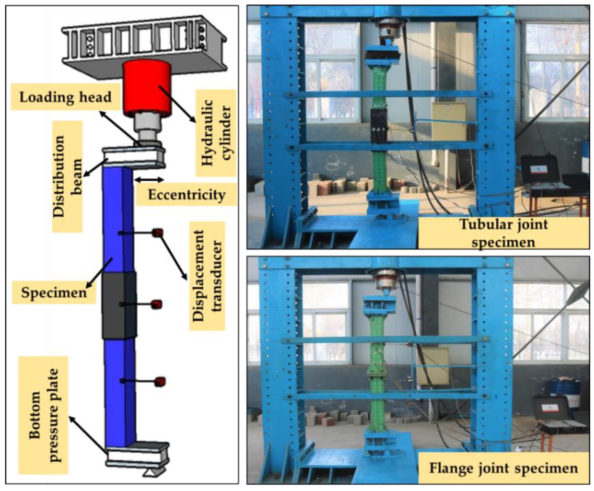
3.1. Overview of the Test

The laboratory experiment is carried out at the Underground Support Scientific Research Base of Shandong University, China. This test base is equipped with a large hydraulic servo system and a reaction force facility, with a maximum strength of more than 300 KN. As shown in Figure 6, the test is carried out by means of a bending test device, which can use the loading indenter to achieve different eccentricities. The specimen is intended to select a tubular joint specimen, a flange joint specimen, and a CFST member without a joint. The specimen parameter design is selected by the common parameters on-site, of which the component is CFST150×8 (a steel tube edge length of 150 mm, a wall thickness of 8 mm, and core concrete C40). No joint, tubular joint and flange joint parameters selection is shown in Table 1, Table 2 and Table 3. The loading scheme adopts gradient loading, and the vertical and lateral displacement of the member is observed by uniformly arranging the displacement meter in the cylinder and across the middle. The specimen length is set to 1500 mm, and the loading eccentricity E/d = 1, where E/d represents the distance from the center of the specimen to the loading position or the ratio of E to the length of the steel tube edge d.

3.2. Analysis of Test Results

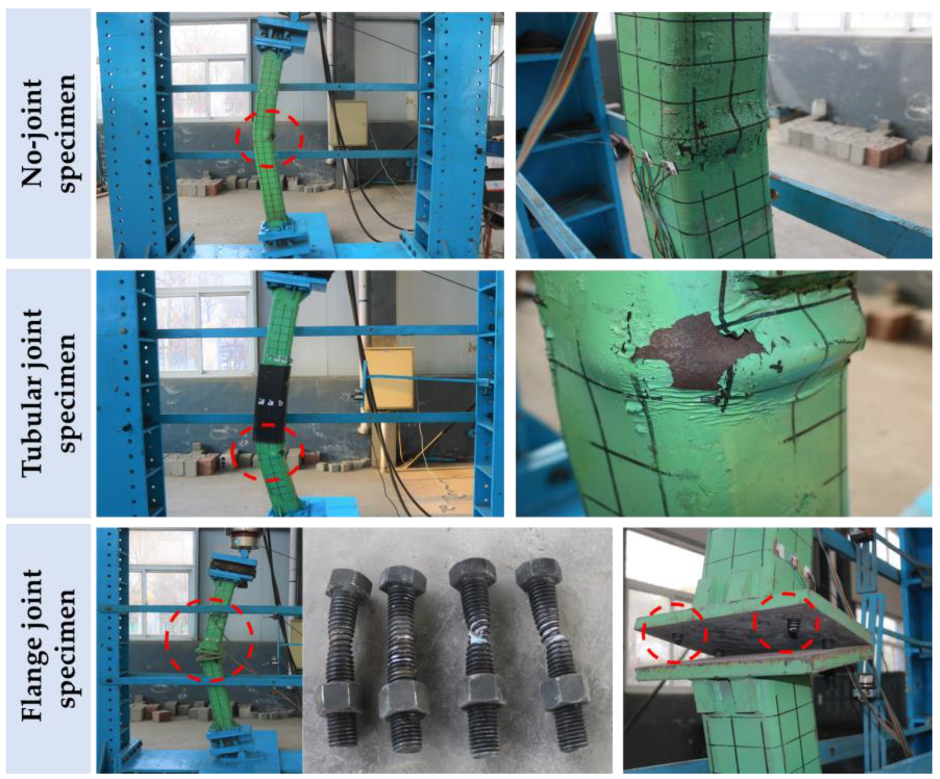
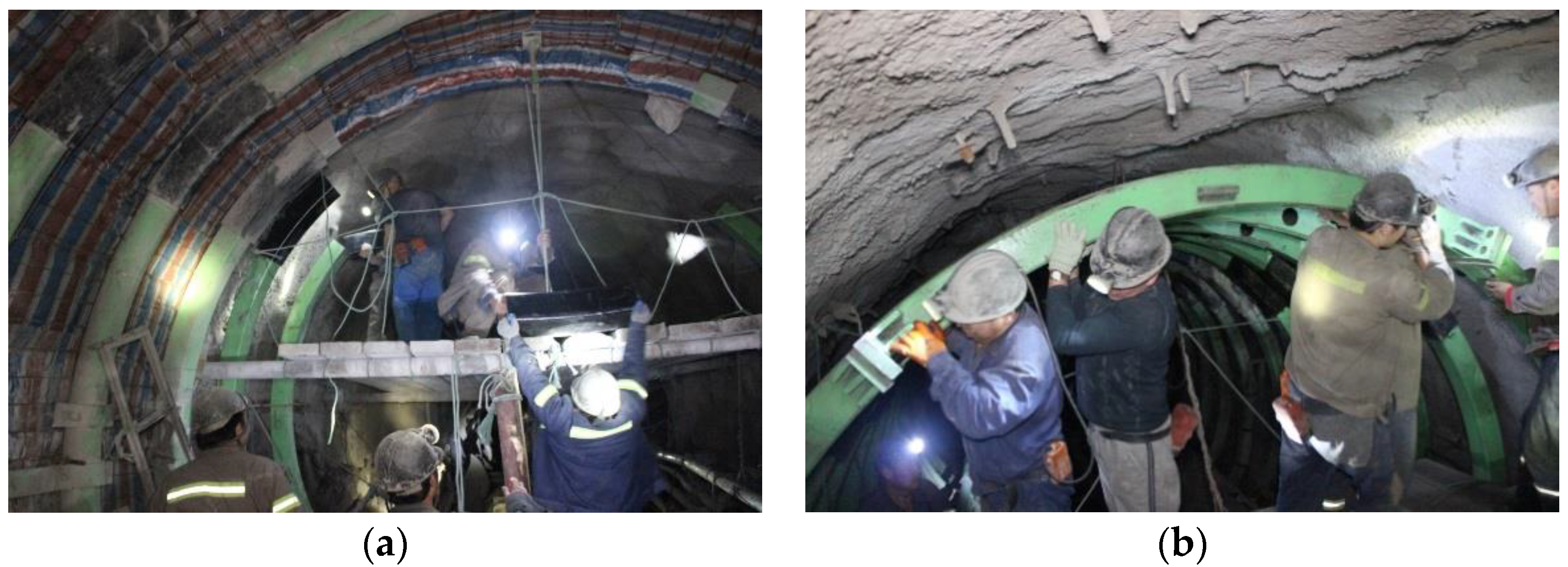
3.2.1. Experimental Phenomena

Figure 7 shows the deformation failure phenomenon in the process of three types of specimen testing. It can be found that in the component bending test, the jointless component and the joint component show different deformation failure forms:
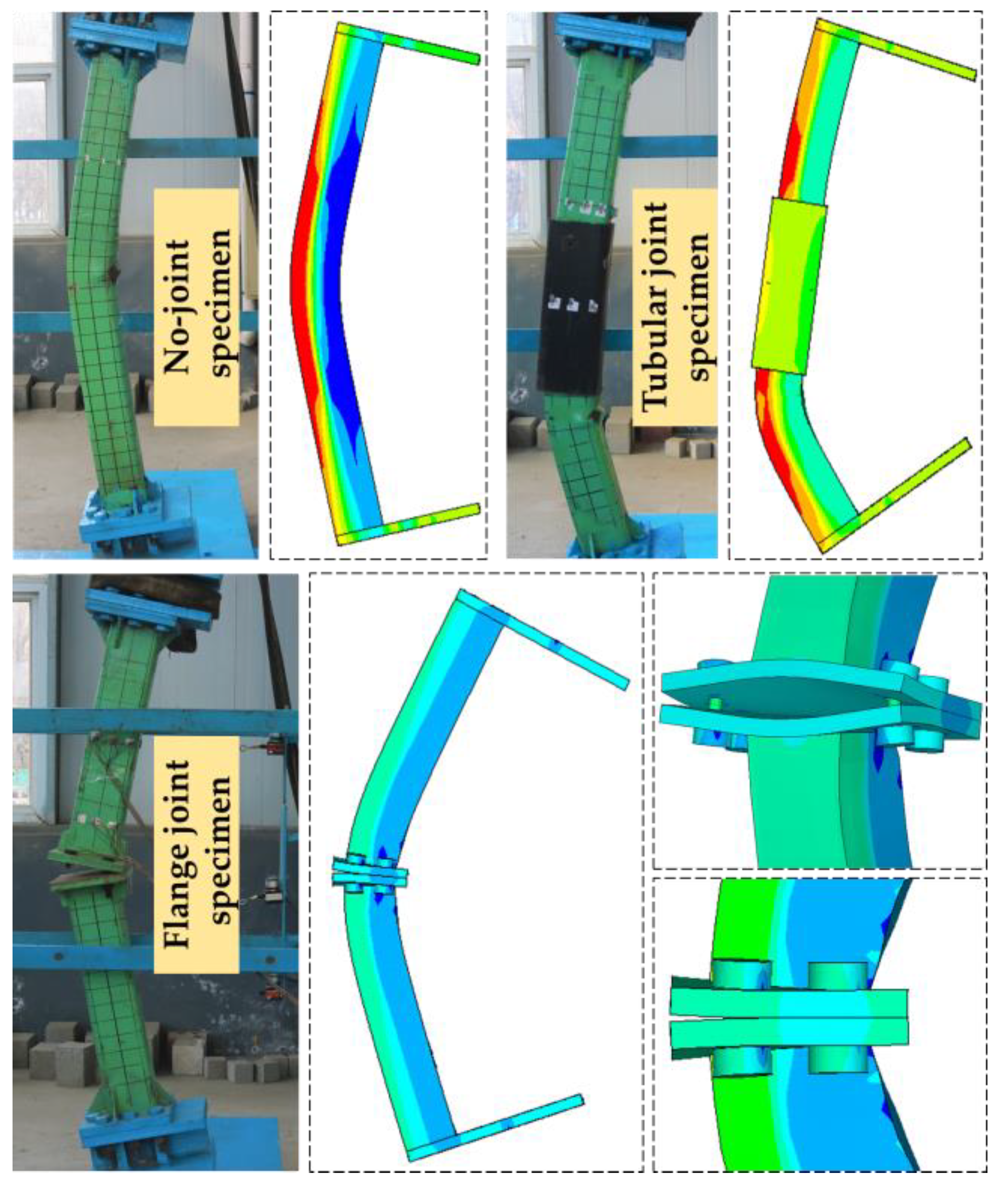
The jointless components are bent uniformly, the steel tube in the pressure area of the midpoint section is bent, and the patent leather falls off after the ultimate load is reached.
The failure form of the tubular joint component is closer to that of the jointless member, but the weak section is located at the junction between the two ends of the tubular and the CFST component, the steel tube bending, the patent leather shedding is obvious, and the deformation failure mode is consistent with the description of Section 2.1.
During the test of the flange joint member, the bending appears to be polyline-shaped and the final failure form ends due to bolt pulling, the flange plate is not significantly deformed, and the failure mode is consistent with the description of Section 2.2.

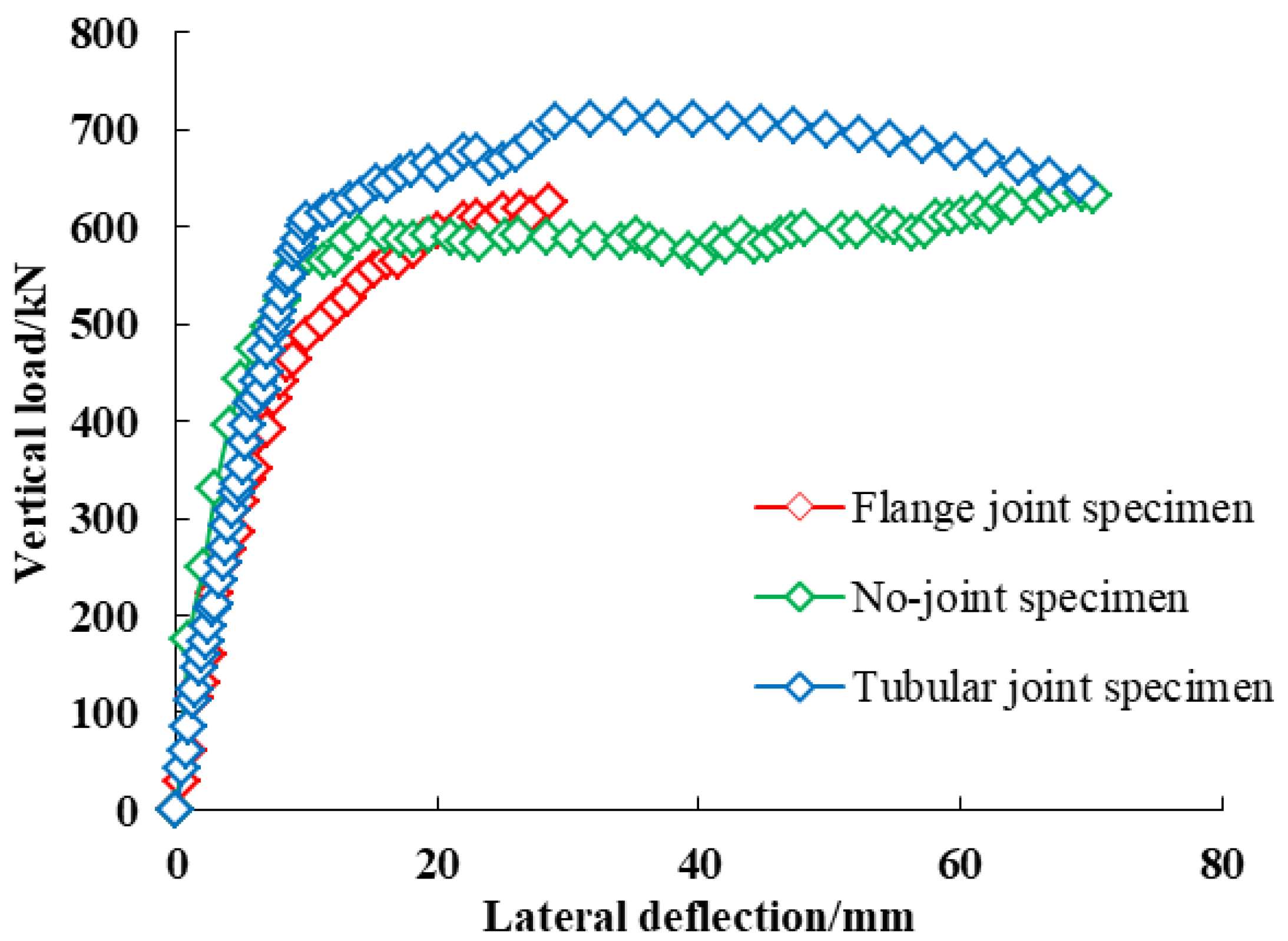
3.2.2. Load Deformation Curve

Figure 8 shows the load–lateral deflection curve of the three types of specimens, combined with the analysis of the above test phenomena:
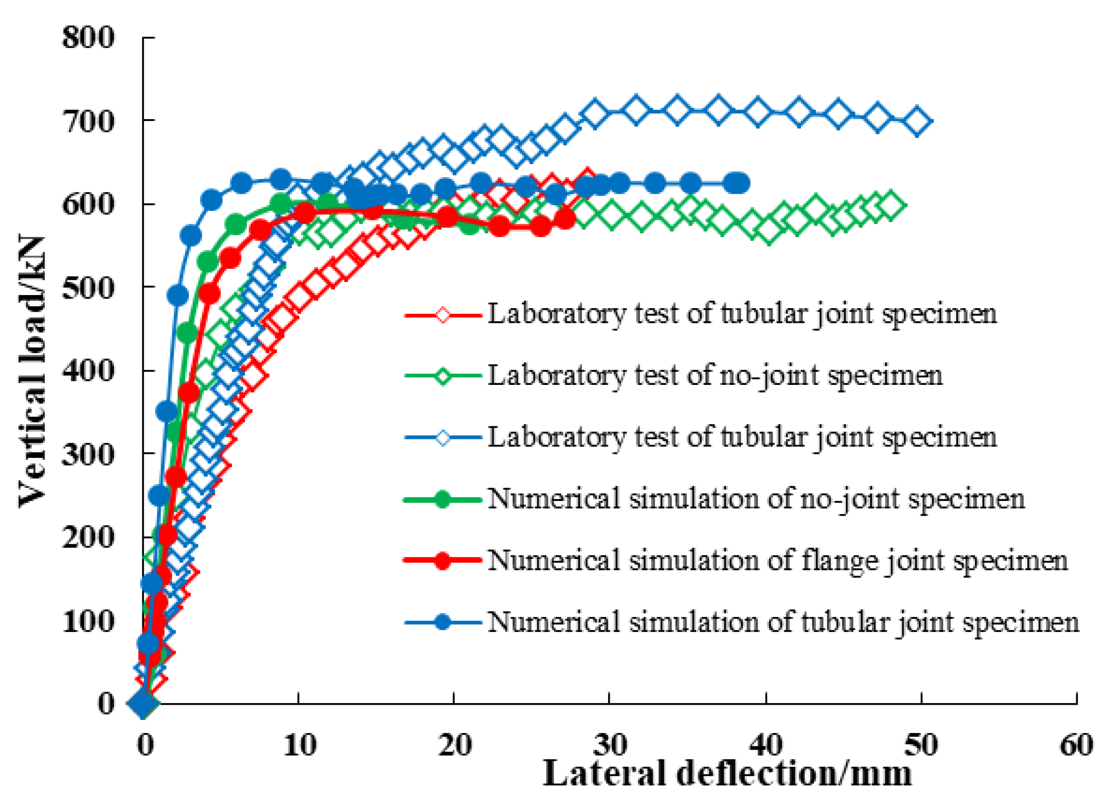
The stiffness of the tubular joint and the no-joint member is similar, and after yielding, the strength of the tubular joint is significantly higher than that of the non-joint component; the stiffness of the flange joint is gradually reduced until the brittleness is destroyed.
The ultimate bearing capacity of the jointless member in the specimen is 606.826 KN, which is not very different from the bearing capacity of the tubular joint specimen of 623.639 KN, of which the flange joint specimen is the smallest, with a bearing capacity of 544.92 KN.
Due to bolt pulling, the flange joint shows typical brittle damage, resulting in instantaneous failure of the arch; no joint specimen and tubular specimen have better ductility, and the tubular joint has higher yield strength and ultimate strength due to the strengthening effect of the tubular joint.

4. Numerical Comparison Test of Mechanical Properties of Joint Bending

In view of the high cost of indoor testing and the complexity of the joint components themselves and the force performance, in order to avoid accidentality and discrete type of test results, this section establishes numerical analysis models of different types of joint components through ANSYS numerical simulation methods and compares and analyzes them with the indoor test results to verify the correctness of the numerical test results.

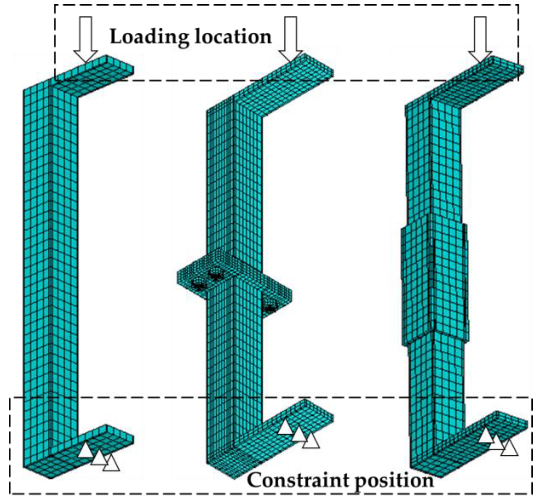
4.1. Simulation Scheme and Parameter Selection

In this section, the numerical test of bending of CFST components, tubular joints, and flange joint components is carried out, and the specimen size, loading conditions, and boundary conditions are consistent with the indoor test. Figure 9 shows the numerical analysis model of each component, in which the SOLID45 element is selected for the steel pipe, the SOLID65 element is used for core concrete, and the CONTAL173 unit is used for the contact between the steel pipe and core concrete. The steel adopts a tri-fold line constitutive model, and the constitutive relationship curve can refer to the formula (2). The stress–strain curve of the material was established using the ANSYS multilinear servo reinforcement model KINH.
Elastic   segment :   σ = ε E s ,   0 ε ε y
Yield   segment :   σ = ε E s 20 σ y 20 + σ y ,   ε y ε ε u
Plastic   segment :   σ = σ u ,   ε ε u
The plastic properties of the concrete in the CFST structure are quite different from those of ordinary concrete due to the constraint of the steel pipe. Lin-Hai Han fully considered the binding effect of a steel pipe on concrete, and after a large number of tests and finite element research, proposed a core concrete stress–strain formula suitable for a steel pipe concrete structure [23]. In this section, the multilinear servo reinforcement model KINH is used to construct the stress–strain curve of concrete materials.

4.2. Comparative Analysis of Test Results

Figure 10 is a load stress cloud diagram of the specimen, and the analysis of the whole process of the test shows that the specimen has the following phenomena:
The joint specimen has essentially no obvious deformation before the load reaches the peak, and as the load gradually increases, the middle of the specimen slides to the left, and the test phenomenon and failure that form under the same loading conditions are consistent with the indoor test results, and the failure mode is smooth curve destruction.
In the loading process of the tubular joint specimen, with the gradual increase in the load, due to the constraint of the tubular, the deformation of the concrete components of the steel pipe is limited, so that it bends and deforms around the upper edge of the tubular. At the same time, the tubular joint has undergone local deformation, and the steel pipe and tubular at the contact site have produced an obvious stress concentration, and the destruction phenomenon is consistent with the indoor test results.
In the ultimate failure state of the flange joint, the bolt in the tension zone shrinks significantly. Overall, the deformation of the test piece joint area is small, and the overall deformation form is polyline-shaped.
As shown in Figure 11, the ultimate bearing capacity of the indoor test and the numerical test of the nodal component is 606.826 KN and 630.017 KN, respectively, and the difference rate is 3.82%. The yield-bearing capacity of the tubular joint component indoor test and the numerical test was 623.639 KN and 631.64 KN, respectively, and the difference rate was 1.28%; the yield-bearing capacity of the flange joint component indoor test and the numerical test were 544.92 KN and 568.615 KN, respectively, and the difference rate was 4.35%. Comprehensive indoor and numerical test phenomena and ultimate load analysis show that the numerical calculation and analysis in this paper can meet the needs of the study of the mechanical characteristics of such supporting structures.

5. Numerical Comparison Test of Mechanical Properties of Joint Bending

The bending moment–axial force strength curve (M-N curve) can be obtained by changing the loading eccentricity of the specimen. M represents the ultimate bending moment value of the specimen under bending failure, and N represents the ultimate axial compression bearing capacity of the specimen under bending failure. The curve consists of M-N points, which represent the strength envelope, the intersection point between the curve and the M axis indicates the ultimate pure bending moment of the specimen, and the intersection point with the N axis indicates the axial pressure-bearing capacity when the eccentricity is 0. M can be obtained by Formula (4).
M = N(e + Δl)
e is the eccentric distance of the load; Δl is the lateral deflection.
Figure 12 is the M-N strength envelop curve of the no-joint member, tubular joint member, and flange joint member with eccentricity E/d of 0, 1, 2, 3, 4, and 5 based on laboratory test conditions. Only when the internal force of the arch member is within the envelope do the joints have sufficient strength.
It can be seen from the curve trend that the axial compression strength of each specimen is similar, indicating that the axial compression strength is mainly determined by the arch cross-section construction. The bending strength of the tubular joint is significantly greater than that of no joint member and flange joint member. The strength of the flange joint is less than that of no joint member due to brittle failure. In this section, the numerical tests of tubular joint and flange joint specimens under different eccentricities are carried out by using the above numerical test analysis method, and the M-N strength curves under different joint structural parameters are obtained.

5.1. Test Protocol

The tubular joint specimen considers two key parameters of tubular length and tubular wall thickness. The flange joint specimen considers the flange thickness and bolt diameter. The joint parameters are selected on the premise of meeting the requirements of the on-site application, and the parameters of the CFST component are consistent with the laboratory test, which is CFST150×8, as shown in Table 4.
In order to facilitate the comparative analysis of the test results, five no-joint comparison components CFST150×8 were added. The setting of the loading eccentricity rate is achieved by changing the load position of the specimen, where E/d takes 0, 1, 2, 3, 4, 5. The parameters of the test reference specimen are consistent with the indoor test, and the detailed test development plan is shown in Table 5 below, of which NCJS represents no joint-less member. CJS-AiBj represents the tubular joint, where A represents the length of the tubular, the value of i represents the value of three kinds of tubular length, B represents the wall thickness of the tubular, and j represents the value of the wall thickness of the three tubular joints. FJS-CmDn represents the flange joint, where C represents the bolt diameter, the m value represents the three bolt diameter values, and D represents the flange thickness. The n value represents the value of the three thicknesses of the flanges.

5.2. Analysis of Test Results

5.2.1. Tubular Joint Components

Figure 13 shows the M-N curves for different bushing lengths, which can be seen from the curve analysis:
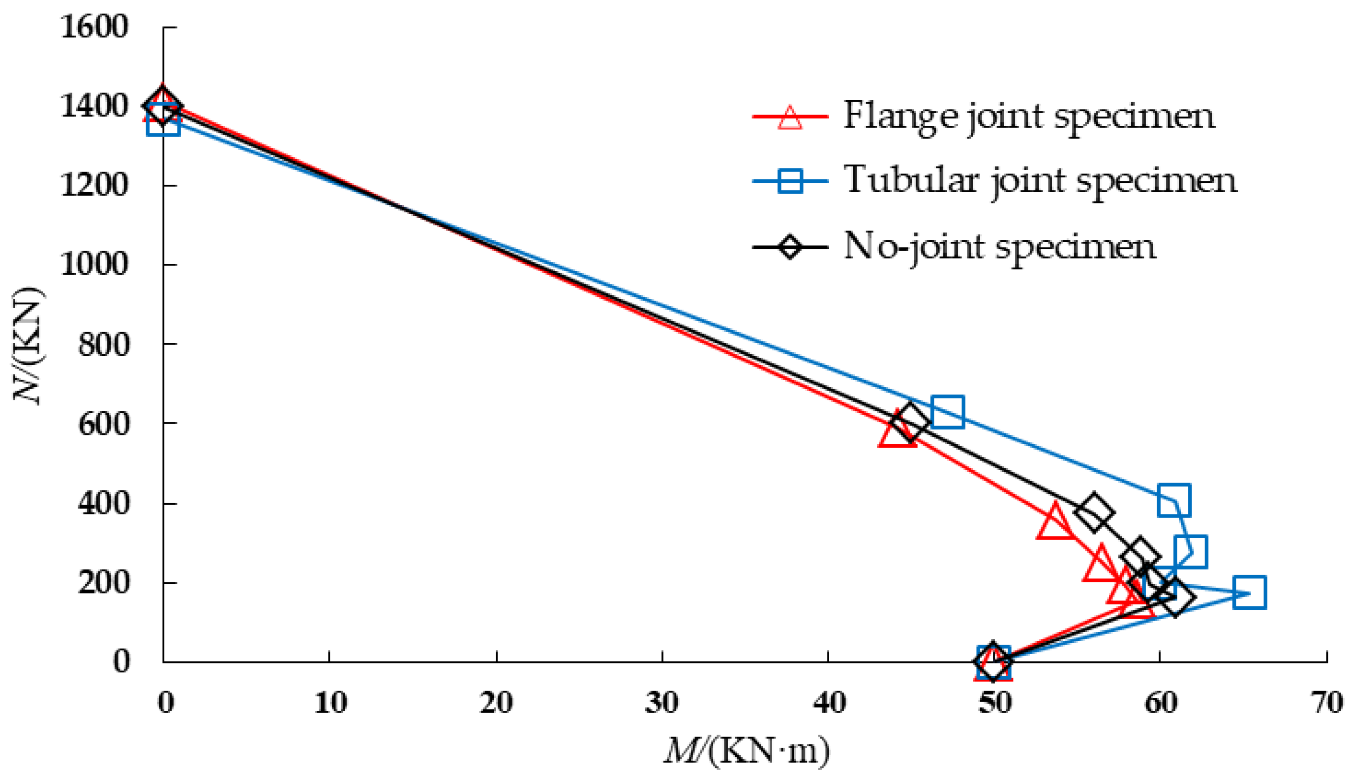
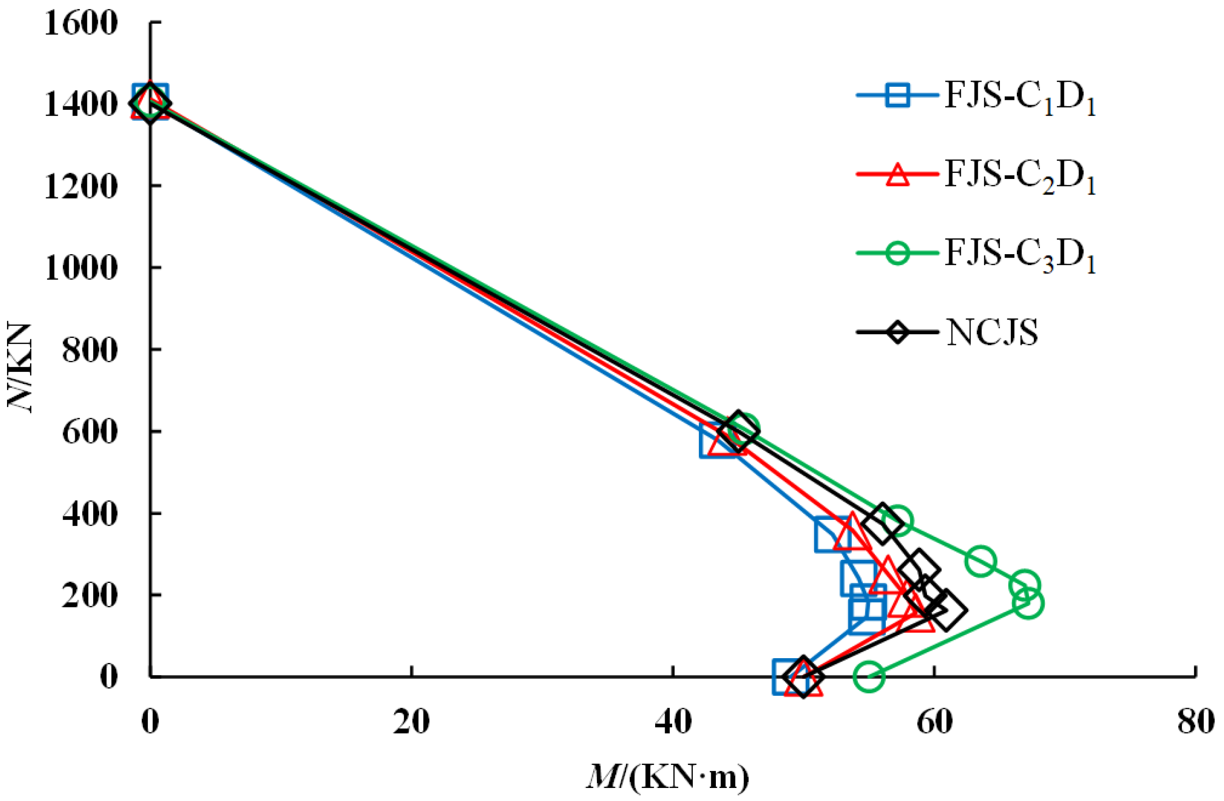
The trend pattern of the NCJS specimen and the tubular joint specimen is consistent, and the distance between the tubular joint specimen curve and the intersection point of the M axis and the right vertex of the curve is larger than that of the NCJS specimen, which indicates that the bending-bearing capacity of the tubular joint under the action of axial force is greater than that of the NCJS specimen.
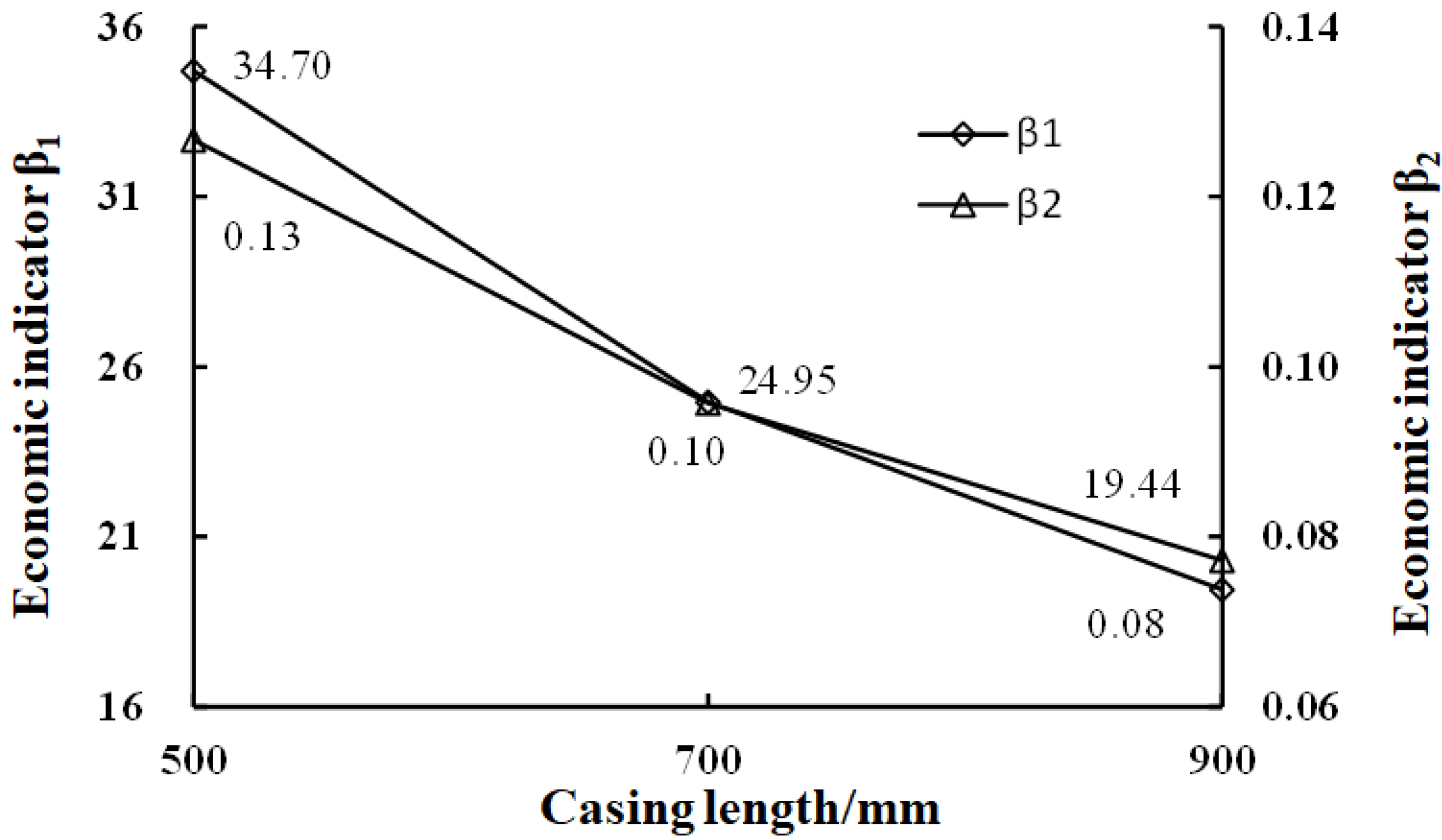
The spacing of each curve decreases from basically unchanged to gradually increasing with a decrease in the N value, indicating that the length of the tubular joint has little impact on the axial pressure resistance of the bending specimen and has a significant impact on the bearing capacity of the bending resistance.
Figure 14 shows the M-N curves for different tubular thicknesses, as can be seen from the curve analysis:
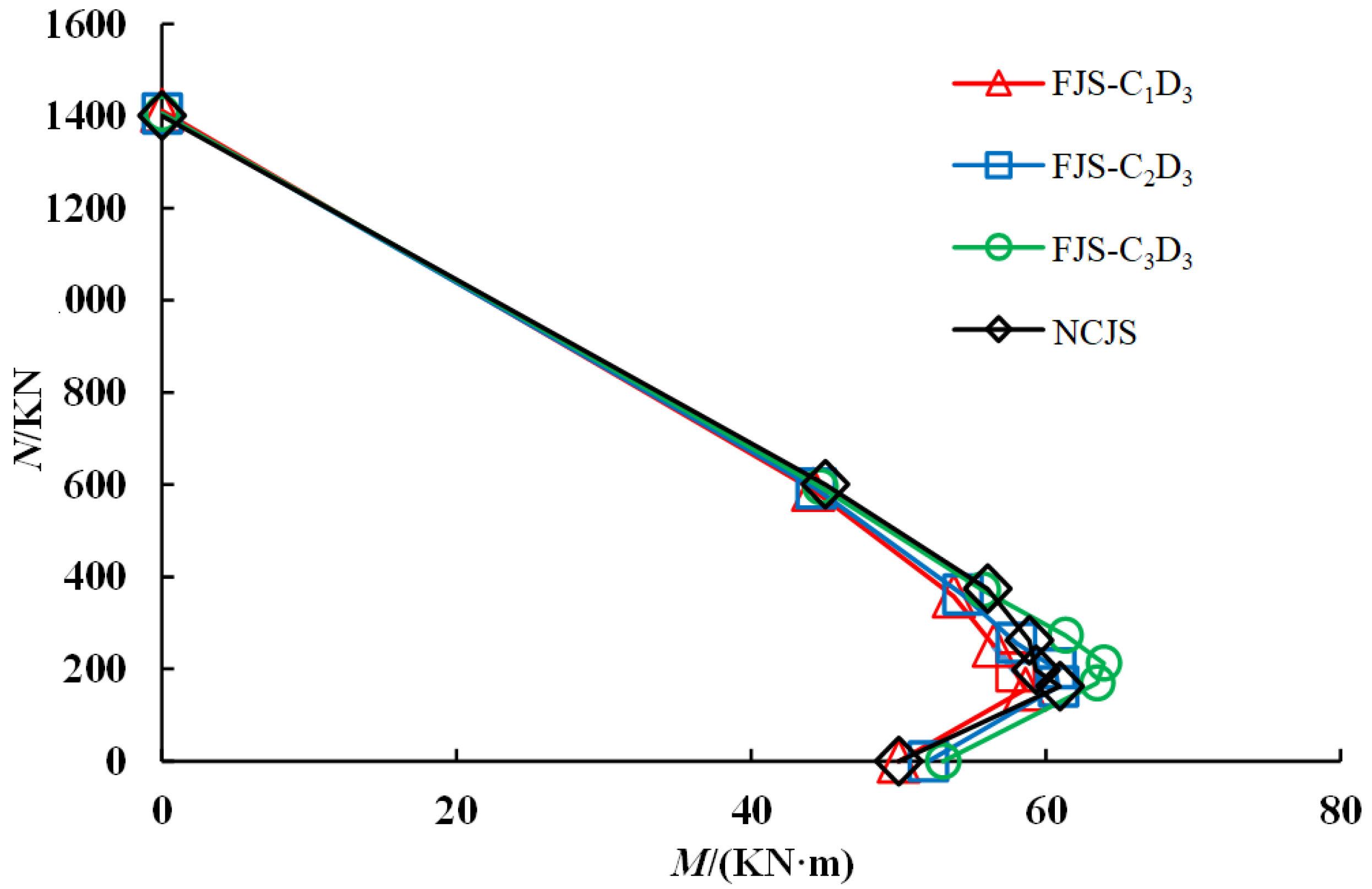
The NCJS specimen is consistent with the trend pattern of the specimen of different tubular thicknesses, the influence of different tubular lengths is consistent, and the bending-bearing capacity of the tubular joint under the action of axial force is greater than that of the NCJS specimen.
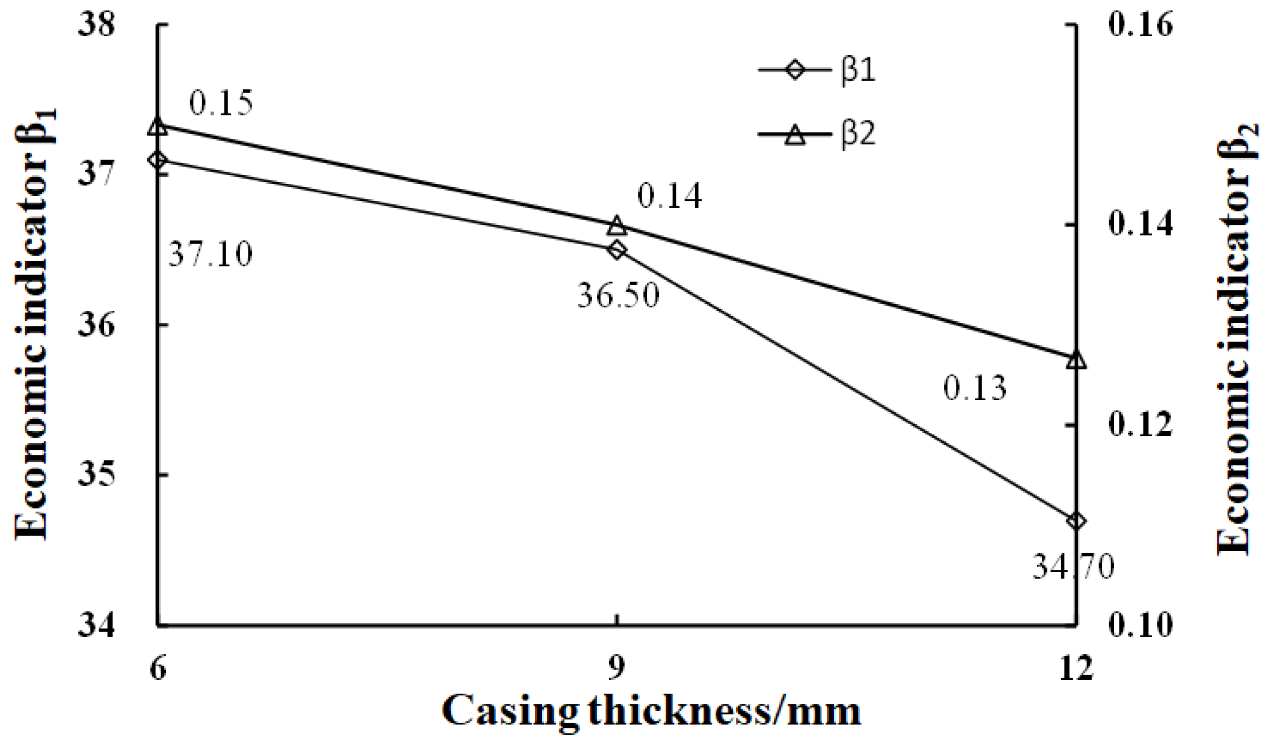
The spacing of each curve is basically the same, indicating that the wall thickness of the tubular joint has an impact on the bearing capacity of axial pressure and the bearing capacity of bending resistance, but it is not obvious.

5.2.2. Flange Joint Components

Figure 15 shows the M-N curves for different bolt diameters, which can be seen from the curve analysis.
The bolt diameter does not have a significant impact on the strength envelope of the specimen, and the spacing of each curve remains basically unchanged, mainly because the bending strength curve of the specimen is derived from the yield strength, and the mechanical properties after the joint yield are not considered. The stiffness and yield strength of the elastic section of the flange joint are controlled by the thickness of the flange, and the role of the bolt diameter is mainly reflected in the ductility section.
Figure 16 shows the M-N curves of different flange thicknesses, which can be seen from the curve analysis: The spacing of each curve gradually increases with the decrease in the N value, which shows that the flange thickness has basically no effect on the axial pressure resistance of the bending specimen. The impact of the bearing capacity of the anti-bending is more significant.

5.3. Design Recommendations

Different joint forms and composition parameters have a significant impact on the bending mechanical properties of CFST components, and most of the current tunnel CFST arch design is based on engineering analogies and no quantitative design consideration method is proposed, resulting in conservative joint design parameters and high costs. Alternatively, the design parameters cannot adapt to the geological profile of the site, becoming a weak link in tunnel excavation. Based on the above analysis, the following design is carried out for the CFST arch joints.

5.3.1. Joint Form Selection

Analysis of force performance from the joint: In view of the severe deformation of the surrounding rock of the deep roadway, the use of flange joint bolts and weld strength may become weak links in the support process, while the tubular joint force transmission mechanism is clear, the bearing capacity is high, and it can be applied to the deep roadway project with complex geological conditions such as soft rock and high stress.
From the on-site construction, as shown in Figure 17, according to the author’s team’s early field tests on the two types of joints, it can be understood that for the tubular joint structure, production is simple, the construction is convenient, the processing cost is low, and the materials are widely used, which greatly reduces the construction difficulty and economic cost. Flange joints in the construction process add welding, bolting, and other additional operation links, and are limited to the construction conditions and bolt piercing difficulties, resulting in a great reduction in construction efficiency. Therefore, the joint form selected should be a tubular joint.

5.3.2. Joint Parameter Design

Tubular joint design parameters cannot be too conservative, should fully consider the influence of joint construction parameters on the mechanical properties of the CFST arch, clarify the key structural parameters in different joint failure modes according to the bending strength, and check the results on the basis of meeting the support needs, so that the selection of support parameters achieve economic optimization.
Combined with the analysis of the influence mechanism of tubular joint parameters, the optimal tubular parameters are selected from the perspective of safety and economy, and the economic indicators with an eccentricity rate of 1 are defined as β1 = N/S, while β2 = M/S is used as a reference metric for evaluating the cost performance of a joint when designing it, where S is the amount of steel used for tubular (mm3). The larger the value of β1 and β2, the higher the cost performance of the selected joint. From the comparative analysis of Figure 18 and Figure 19, it can be seen that the bushing length is most cost-effective when 500 mm is selected, while the wall thickness is 6 mm and 9 mm. The price difference is not great, so the wall thickness is 9 mm.

6. Conclusions

(1)
The bending behavior of the no-joint specimen and the tubular joint specimen is similar, showing uniform curve deformation. The flange joint shows typical brittle damage due to bolt pulling, showing a polyline-shaped failure form. The ultimate bearing capacity of the n- joint component is 606.826 KN, which is not much different from the bearing capacity of the tubular joint specimen at 623.639 KN, and the flange joint specimen is the smallest, with a bearing capacity of 544.92 KN. The tubular joint has higher yield strength and limited strength due to the reinforcing action of the sleeve.
(2)
The M-N envelop curve under different joint parameters was obtained, the relationship between joint parameters and bending bearing performance was quantified, and the influence mechanism of joint parameters was clarified. Engineering design suggestions are proposed: The force transmission mechanism of the tubular joint is clear, of which the bearing capacity is high, and it can be applied to the deep roadway project of soft rock, high stress, and other complex geological conditions, with a length of 500 mm and a wall thickness of 9 mm. The tubular joint should be used as the preferred joint connection form for the CFST support arch.
(3)
This paper compares the strength of different types of joints and the no-joint component, which provides a reference for the relevant design. In the future, the quantitative analysis and evaluation of the joint strength and stiffness on the overall strength and stiffness of the arch should be carried out to establish a quantitative design method for concrete-filled steel tubular arch joints in underground engineering.

Author Contributions

Conceptualization, H.S. and W.L.; methodology, H.S. and W.L.; software, Y.L. and J.W.; validation, J.W. and X.L.; formal analysis, H.S. and J.W.; investigation, H.Y.; resources, L.W.; data curation, J.W.; writing—original draft preparation, H.S.; writing—review and editing, H.Y.; visualization, W.L. and L.W.; supervision, Q.R. and D.H.; project administration, X.X.; funding acquisition, H.S and W.L. All authors have read and agreed to the published version of the manuscript.

Funding

This research was funded by the Shandong Provincial Housing and Urban-Rural Construction Science and Technology Program (2021-K5-34), and the Shandong Jianzhu University Doctoral Research Fund Project (XNBS20106).

Institutional Review Board Statement

Not applicable.

Informed Consent Statement

Not applicable.

Data Availability Statement

Not applicable.

Conflicts of Interest

The authors declare no conflict of interest.

References

  1. He, M.C. Progress and challenges of soft rock engineering in depth. J. China Coal Soc. 2014, 39, 1409–1417. [Google Scholar]
  2. Wang, Q.Z.; Xie, W.B.; Jing, S.G. Instability mechanism and control technology of chamber group surrounding rock in complex structural area. J. Min. Saf. Eng. 2014, 31, 263–269. [Google Scholar]
  3. He, M.C.; Jing, H.H.; Sun, X.M. Mechanics of Soft Rock Engineering; Science Press: Beijing, China, 2002. [Google Scholar]
  4. Wang, L.; Wang, Q.; Huang, Y.B. Study on deformation mechanism and support technology of deep cross-measure roadway under high stress. J. Min. Saf. Eng. 2019, 36, 112–121. [Google Scholar]
  5. Meng, Q.; Han, L.J.; Zhang, F.E. Coupling support effect on high-stress deep soft rock roadway and its application. Rock Soil Mech. 2017, 38, 1424–1435. [Google Scholar]
  6. Hou, C.J. Key technology for surrounding rock control in deep roadway. J. China Univ. Min. Technol. 2017, 46, 970–978. [Google Scholar]
  7. Liao, W.; He, P.; Yan, D.M. Study on stress distribution law of steel arch frame for initial support of tunnel. J. China Railw. Soc. 2017, 39, 140–147. [Google Scholar]
  8. Yu, F.C.; Zhang, D.L.; Fang, Q. Experimental study on composite support characteristics of high strength reinforced grid concrete. J. Civ. Eng. 2015, 48, 104–111. [Google Scholar]
  9. Li, W.T.; Wang, Q.; Wang, D.C. Experimental study confined concrete on short columns under axial load of U-type arch centering and its application in mine. J. Min. Saf. Eng. 2014, 31, 1–9. [Google Scholar]
  10. Ellobody, E.; Young, B.; Lam, D. Behaviour of normal and high strength concrete-filled compact steel tube circular stub columns. Constr. Steel Res. 2006, 62, 706–715. [Google Scholar] [CrossRef]
  11. Hassan, M.M.; Mahmoud, A.A.; Serroe, M.H. Behavior of concrete-filled double skin steel tube beam-columns. Steel Compos. Struct. 2016, 22, 1141–1162. [Google Scholar] [CrossRef]
  12. Han, L.H.; Yang, Y.F. Study on axial bearing capacity of concrete-filled-steel-tube columns with rectangular section. China Civ. Eng. J. 2001, 34, 22–31. [Google Scholar]
  13. Li, X.W.; Zhao, J.H.; Zhu, T.D. Mechanics behavior of axially loaded short columns with concrete filled square steel tube. China J. Highw. Transp. 2006, 19, 77–81. [Google Scholar]
  14. Elremaily, A.; Azizinamini, A. Experimental behavior of steel beam to CFT column connections. J. Constr. Steel Res. 2001, 57, 1099–1119. [Google Scholar] [CrossRef]
  15. Wang, Y.Q.; Zhang, Y.; Shi, Y.J. Analysis of load capacity of new-style joints between cable and concrete-filled steel tube arch bridge. J. Archit. Civ. Eng. 2005, 22, 55–58. [Google Scholar]
  16. Zhu, T.; Liang, H.J.; Lu, Y.Y.; Li, W.J.; Zhang, H. Axial behaviour of slender concrete-filled steel tube square columns strengthened with square concrete-filled steel tube jackets. Adv. Struct. Eng. 2020, 23, 1074–1086. [Google Scholar] [CrossRef]
  17. Hanifehzadeh, M.; Aryan, H.; Gencturk, B.; Akyniyazov, D. Structural response of steel jacket-UHPC retrofitted reinforced concrete columns under blast loading. Materials 2021, 14, 1521. [Google Scholar] [CrossRef]
  18. Li, S.C.; Lu, W.; Wang, Q. Study on failure mechanism and mechanical properties of tubular joints of square steel confined concrete arch. Eng. Fail. Anal. 2018, 92, 539–552. [Google Scholar] [CrossRef]
  19. Gao, Y.F.; Wang, B.; Wang, J. Test on structural propertyand application of concrete-filled steel tube support of deep mine and soft rock roadway. Chin. J. Rock Mech. Eng. 2010, 29, 2604–2609. [Google Scholar]
  20. Zang, D.S.; Li, A.Q. Study on concrete-filled steel tube supports. Chin. J. Geotech. Eng. 2001, 23, 342–344. [Google Scholar]
  21. Sun, H.B. Study on Stability Bearing Mechanism and Key Technologies of Assembly Confined Concrete Support for Large Section Tunnel. Ph.D. Thesis, Shandong University, Jinan, China, 2019. [Google Scholar]
  22. Lu, W.; Sun, H.B. Study on support characteristic curve of primary support structures in underground excavation considering bond-slip behavior. Adv. Struct. Eng. 2021, 24, 497–508. [Google Scholar] [CrossRef]
  23. Hanl, H.; Yao, G.H.; Tao, Z. Performance of concrete-filled thin-walled steel tubes under pure torsion. Thin-Wall Struct. 2007, 45, 24–36. [Google Scholar]
Figure 1. Schematic diagram of restrained concrete arch joint.
Sustainability 14 08916 g001
Figure 2. Schematic diagram of tubular joint.
Sustainability 14 08916 g002
Figure 3. Failure mode of tubular joint. (a) Steel pipe concrete members are damaged. (b) Bushing joint destruction.
Sustainability 14 08916 g003
Figure 4. Failure modes of flange joints.
Sustainability 14 08916 g004
Figure 5. Failure modes of flange joints. (a) Bolt broken. (b) Flange plate bending. (c) CFST deformation.
Sustainability 14 08916 g005
Figure 6. Compression bending tests of different types of joints.
Sustainability 14 08916 g006
Figure 7. Deformation and failure modes of various joints.
Sustainability 14 08916 g007
Figure 8. Load lateral deflection curve.
Sustainability 14 08916 g008
Figure 9. Boundary conditions and numerical model of compression-bending component.
Sustainability 14 08916 g009
Figure 10. Effective stress nephogram specimens.
Sustainability 14 08916 g010
Figure 11. Effective stress nephogram at each stage of specimen loading.
Sustainability 14 08916 g011
Figure 12. Envelope of compressional-flexural strength.
Sustainability 14 08916 g012
Figure 13. M-N curves under different lengths.
Sustainability 14 08916 g013
Figure 14. M-N curves under different thicknesses.
Sustainability 14 08916 g014
Figure 15. M-N curves under different bolt diameters.
Sustainability 14 08916 g015
Figure 16. M-N curves under different flange thicknesses.
Sustainability 14 08916 g016
Figure 17. Field construction of arch frame with different types of joints. (a) On-site construction of tubular joint. (b) On-site construction of flange joint.
Sustainability 14 08916 g017
Figure 18. Economic indicators β1 and β2 under different tubular lengths.
Sustainability 14 08916 g018
Figure 19. Economic indicators β1 and β2 under different thicknesses.
Sustainability 14 08916 g019
Table 1. Structural parameters of no joint.
Component FormArch TypeTube Wall Thickness/mmTubular Length/mmCore Concrete Strength/MPa
No joint specimenCFST150-88150C40
Table 2. Structural parameters of tubular joint.
Component FormArch TypeTubular Wall Thickness/mmSleeve Width/mmTubular Length/mmSpecimen Length/mm
Tubular jointCFST150-8121805001500
Table 3. Structural parameters of flange joint.
Component FormArch TypeFlange Thickness/mmBolt Diameter/mmSpecimen Length/mm
Flange connectionCFST150-825221500
Table 4. Contrast of parameters of specimen.
NumberingParametric Variable123
AiTubular length/m0.50.70.9
Bjtubular wall thickness/mm6912
CmBolt Diameter/mm222426
Table 5. Specimen test.
Scheme NumberParameter 1Parameter 2QuantityEccentricity
(E/d)
AiTubular length/m0.50.70.9
Bjtubular wall thickness/mm6912
CmBolt Diameter/mm222426
Publisher’s Note: MDPI stays neutral with regard to jurisdictional claims in published maps and institutional affiliations.

