Article

An Energy Storage Assessment: Using Frequency Modulation Approach to Capture Optimal Coordination

1
Faculty of Automation, Huaiyin Institute of Technology, Huai’an 223003, China
2
Faculty of Electronic Information Engineering, Huaiyin Institute of Technology, Huai’an 223003, China
3
Jiangsu Foreign Expert Workshop, Jiangsu Provincial Department of Sciences and Technology, Huai’an 223003, China
4
Electrical Engineering Department, Faculty of Engineering, Minia University, Minia 61519, Egypt
5
School of Automotive and Transportation Engineering, Guilin University of Aerospace Technology, Guilin 541004, China
6
Department of Electrical Engineering, Balochistan University of Information Technology, Engineering and Management Sciences (BUITEMS), Quetta 1800, Pakistan
*
Authors to whom correspondence should be addressed.
Sustainability 2022, 14(14), 8510; https://doi.org/10.3390/su14148510
Submission received: 4 June 2022 / Revised: 6 July 2022 / Accepted: 7 July 2022 / Published: 12 July 2022

Abstract

:
To reduce the allocation of energy storage capacity in wind farms and improve economic benefits, this study is focused on the virtual synchronous generator (synchronverter) technology. A system accompanied by wind power, energy storage, a synchronous generator and load is presented in detail. A brief description of the virtual synchronous generator control strategy is given. The capacity allocation is based on different optimization goals and the optimal energy storage capacity configuration of the coordinated frequency modulation (FM) control strategy. The detail of the dual-loop control strategy is carried out by establishing the grid-connected transfer function model of the synchronverter energy storage and a theoretical model of life cycle cost is established. The optimal control strategy of coordinated FM for wind storage is implemented using MATLAB software. The simulation showed that the proposed strategy provided the energy storage capacity at high wind speed, which is configured to be 5.9% of the installed capacity of the wind turbine, marking a reduction of 26% compared with the 8% capacity required for independent support. In addition, the proposed method has improved the energy storage capacity configuration of the coordinated FM control strategy.

1. Introduction

To protect the ecological environment and ensure sustainable economic development, the use of wind, solar and other new energy sources to generate electricity has become the focus of authorities [1,2]. Furthermore, with the development of technology and the economy, people’s demand for electricity is rapidly increasing, which leads to the scarcity of traditional energy. New energy sources do not need to consume increasingly exhausted fossil energy, nor will they cause environmental pollution, ensuring sustainable production [3]. While the synchronization characteristic of a synchronous motor can ensure its automatic synchronization with a large power grid, the inverter can only achieve synchronization with the power grid through phase-locked control [4]. In a large power network, the output impedance of the synchronous motor is high due to its winding, which has a strong ability to suppress current disturbance [5]. The inverter has weak resistance to current and is prone to overcurrent. The synchronous motor has a strong ability to cope with external disturbances due to its structural characteristics, while the inverter topology is mainly composed of power electronic devices, which have limited bearing capacity and poor resistance in case of system failure [6]. Therefore, the characteristics of the synchronous motor can ensure the stable operation of the power system. The characteristics of large synchronous motor impedance and large inertia can thus guarantee the stable operation of the power system. A new control method of inverter synchronverter control is proposed to improve the stability of power grid operation [7,8]. The excellent technical characteristics, such as fast output and stable operation, of the ESS are utilized to compensate for the uncontrollable shortcomings of wind turbines and to support the frequency of the system in a stable state in time [9]. The intermittent ability to generate electricity from either a single wind turbine or wind farms, as well as the inherent challenges of supplying and sustaining connectivity to the electrical grid, point to the necessity for energy storage [10]. Energy storage offers a way to collect and balance wind energy as it is produced and store it for use at a later time when demand might outstrip supply. The most practicable or advantageous energy storage technologies for wind generation are said to fall into four categories: battery storage, flywheel storage, compressed air storage, and pumped hydro storage. However, considering the high cost of ESS, it is necessary to study the optimal control strategy of coordinated FM for wind energy storage [10].
In this study, an ESS model is established to conduct parameter tuning and deeply analyze the influence of parameter changes on the stability of each link of the ESS, thereby laying a foundation for the subsequent ESS to be connected to the wind energy system and providing a stable output. Under the condition that the original wind storage coordination FM strategy cannot meet the demand, a wind storage coordination frequency optimization strategy is proposed. Therefore, the optimal allocation of energy storage capacity is studied. Furthermore, due to the high cost of energy storage, we also considered the characteristics and economics of FM technology and proposes an optimal allocation method for energy storage capacity. According to the requirements of FM, the design method of the energy storage rated power and the rated capacity is determined.

2. Background Study

The basic idea of a synchronverter has been provided [11,12], which makes the grid-connected inverter resemble the operational characteristics of SG in various ways. Researchers [13] proposed a synchronverter scheme that reflects the proper operating characteristics of the synchronous machine, whereas the technique reflects the swing equation of conventional SG. Furthermore, operational metrics such as Q and Pf can be compared between the standard SG and synchronverter [14]. However, a current-controlled synchronverter is the same as a current source, providing voltage and frequency support for the system. In [15], a voltage-controlled synchronverter technique is proposed to alleviate the shortcomings of the current-controlled synchronverter. The goal of voltage-controlled synchronverter techniques is to simulate the rotor inertia and system frequency modulation characteristics of SG in frequency control to improve the system’s frequency stability [16]. The reactive voltage relationship is primarily considered in voltage control to control the stable voltage output [17]. The synchronverter performs power management and frequency modulation functions thanks to the power controller and voltage frequency controller [18]. The synchronverter is a system that simulates the inertia of a traditional power system by combining control algorithms, renewable energy sources, energy storage devices, and power electronics [19]. The synchronverter is a system that connects various storage units, generation units, and the utility grid. In today’s grid systems, variable wind turbines are employed, and these turbines are connected with back-to-back inverters, allowing for total decoupling of inertia from the utility grid [18]. The AC to DC converters and an additional inverter at the front end connect the energy storage and wind systems. This system is unresponsive to changes in inertia [12]. According to the literature, the main model concepts for many topologies are identical; however, the implementation of each topology model differs. Only a few topologies use mathematical equations to fully simulate synchronous generator behavior, and only a few topologies use swing equations to copy the synchronous generator’s inconsistent performance. The simple structure of the synchronverter-based wind energy storage system is presented in Figure 1.

2.1. Virtual Synchronous Generator

Synchronverter technology allows embedding the mechanical and electrical transient equation of a traditional synchronous generator into the control strategy of the external power electronic converter of wind power or photovoltaic unit, to simulate the external electromagnetic and mechanical motion characteristics of the synchronous motor [17]. To avoid too complex modelling and give consideration to practicability, the second-order synchronous motor model as the simulation modelling target is used. The motion equation of the second-order rotor of a synchronous motor controlled by VSG can be expressed as
T m T e D ( ω ω r e f ) = J d ω d t d θ 1 d t = ω
In Equation (1), Tm and Te represent the mechanical and electromagnetic torque of the prime mover, respectively; θ1 represents the angle of work; ω and ωref represent the rotor angular velocity and rated angular velocity, respectively; the J parameter is the rotational inertia coefficient of the rotor; and D is the damping coefficient of the rotor.
The stator electrical equation can be expressed as
u a b c = e a b c C s i a b c L s d i a b c d t
In Equation (2), uabc is the stator side-induced electromotive force; eabc is the three-phase output voltage of the stator side; and Ls and Cs are armature inductors and capacitors, respectively.
Using the above two models, the modelling process is relatively simple, but also can ensure the inertia characteristics of the synchronous motor simulated by the inverter.
Low- and high-frequency oscillation phenomena exist in the synchronverter grid-connected system due to external interference and factors of the synchronverter itself [19]. The introduction of virtual synchronization makes the system have low-frequency oscillation characteristics similar to that of a synchronous motor [20]. Furthermore, the combined action of some functions of the synchronverter and external interference will stimulate the original mode change of the inverter and cause the high-frequency oscillation of the grid-connected system [14]. At present, most scholars seldom present the grid-connection stability and mostly use the small-signal model. Researchers [15] have discussed the small-signal model adopted to study the stability of a single machine incorporated into the power grid. Some [16] studied the situation of two machines connected to a microgrid under small-signal interference and also studied the influence of the change in the control parameters and circuit parameters on the stability of the system. Others [18] have derived the synchronous frequency resonance phenomenon excited by the synchronverter access power grid in detail and proposed corresponding measures to suppress the oscillation through analyzing its influencing factors. In [19], the authors adopted the classical method of stability analysis in a power system, taking the power angle and frequency of synchronverter as the state variables, establishing the state–space equation, and used the characteristic root locus method to study the influence of parameter changes on the stability of the system. The authors in [20] studied the stability of a synchronverter connected to a large power grid, establishing the transfer function between output power and input power, and analyzed the dynamic characteristics of the system.

2.2. Frequency Modulation Coordination

The rotor inertia control has a short maintenance time, and the response speed is slow when the rotor pitch control is adopted, so the power of the frequency recovery cannot be provided in time [21]. Therefore, it is difficult to keep the power system frequency in a stable state solely by relying on the wind turbine’s FM. Researchers [22] constructed an FM model covering energy storage and wind farms. It is clear that the addition of energy storage is beneficial to ease the frequency fluctuation of the power grid, but the waste of energy storage is caused to some extent due to the failure to consider the FM method used on wind farms. Therefore, considering only the FM means of energy storage and ignoring the FM means used in wind farms is not conducive to its application in engineering. The authors in [23] used ESS and wind control systems to assist power grid FM successively. Without considering the coordination function of the two, the economic efficiency of frequency regulation is reduced by making full use of their complementary characteristics. Therefore, isolated consideration of wind and energy storage participating in the FM system causes economic loss. This study adopts the coordinated FM control strategy of wind storage and builds the simulation model of the wind storage system and the conventional power system. It analyses the frequency change of the system and improves the technical economy and engineering practicality of the frequency regulation. Meanwhile, coordinated FM of wind storage restrains the secondary frequency drop phenomenon in the process of wind power speed recovery, which is of great significance to transform wind power from FM with the ability to provide an auxiliary service to the participating system and improve the safety and stability of the power grid.

2.3. Optimal Energy Storage Capacity

Energy storage is connected to the power system, which can optimize the FM effect of the wind farm. However, considering the high cost of energy storage, how to optimize the configuration of energy storage capacity and improving the efficiency of wind farm FM has become an urgent problem to be solved [24]. The energy storage capacity allocation methods used to calm the stroke power of wind farms include the economic index optimization method, considering the economy; the frequency-domain analysis method, using spectrum analysis; and the probability statistical method, based on distribution value allocation [25]. The frequency-domain analysis method is described in [26]. Fourier transform is adopted to analyze the output data, to determine the target value to be stabilized and the frequency band where the energy storage is located, and to determine the maximum and minimum value of the accumulated energy storage in the selected period. When the SOC of the ESS is within the allowable range and can maintain the normal operation of the system, the capacity that the ESS needs to be configured to is determined through simulation analysis [27]. When adopting this method, it is necessary to collect the historical data of wind farms, which requires a high degree of sample selection and has a strong dependence on the data. Meanwhile, the energy storage capacity configured by this method is relatively large. Authors [28] have discussed that a probabilistic statistical method be adopted, and that capacity allocation also be carried out based on historical data. Firstly, the component values of the two types of hybrid batteries are separated by the wavelet decomposition method. Then, according to the component value statistics, one determines its distribution law [29]. Different confidence levels are used to determine the capacity of the energy storage configuration. Researchers [28] studied the optimization method of the economic indicators adopted. The optimal economic effect is taken as the objective function, and the mathematical algorithm of chance-constrained programming is adopted to seek the optimal value of the energy storage capacity and configure the capacity needed for economic optimization [29]. A comprehensive optimal allocation method for energy storage capacity is proposed, which is constrained by the operating control energy of the ESS and targeted at the optimization of the FM effect and economic synthesis. By allocating a proper energy storage, the wind farm can adjust the frequency variation of the power grid in time just like traditional power supply, thereby improving the engineering applicability and economy of the combined FM of wind storage.

3. Proposed Methods

3.1. Virtual Synchronous Generator Model

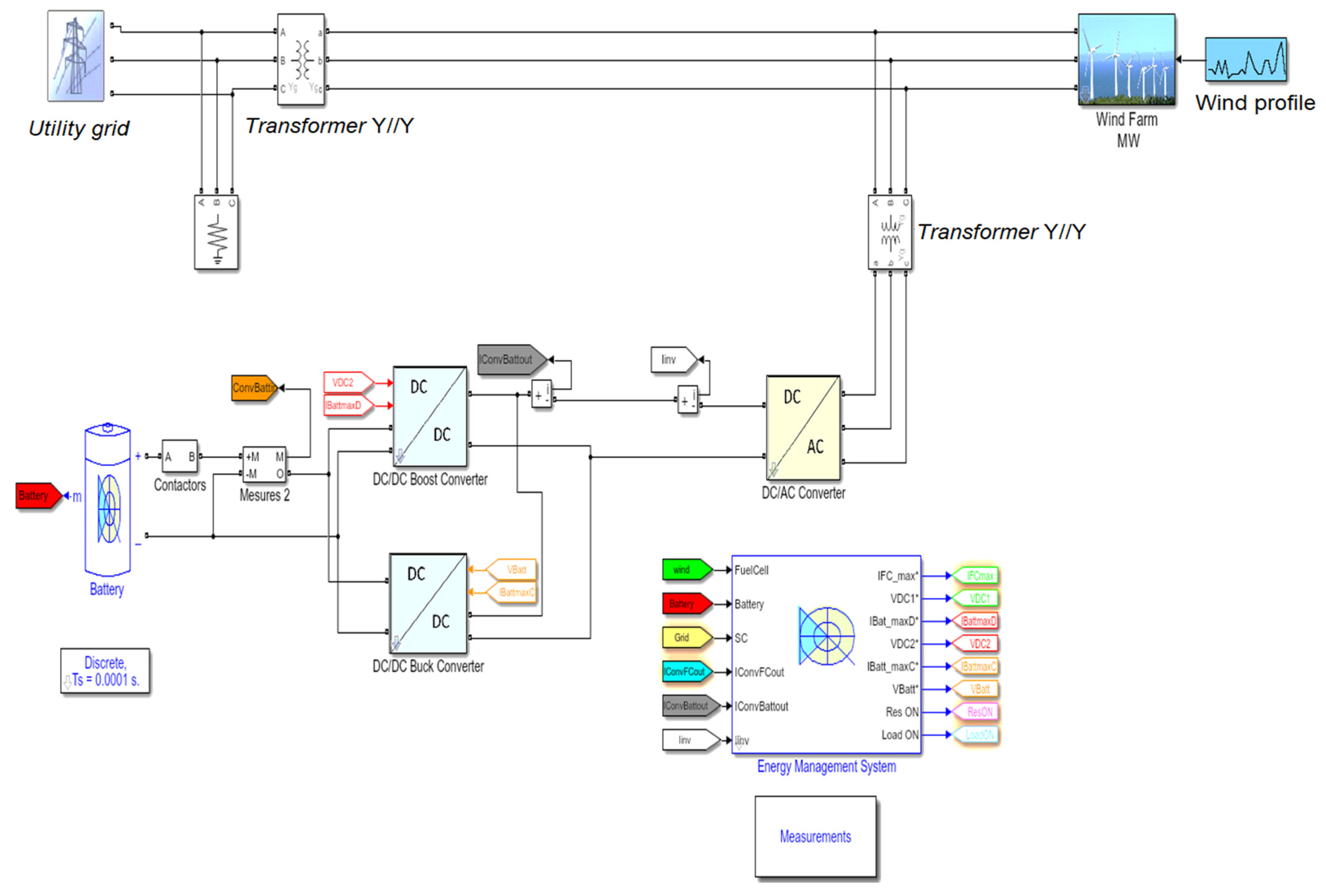
A voltage and current-controlled energy storage synchronverter adopts a double-loop control strategy. The outer loop is an active and reactive power link, through which amplitude and phase are generated. The inner loop is the current loop, which generates the voltage reference value of the pulse modulation signal by inductance current control. In the current-control-type energy storage virtual synchronous machine, the outer loop uses power control to generate the reference current, and the inner loop uses current control to generate the voltage reference signal. According to the control strategy of the virtual synchronous machine for energy storage, the transmission model of the ESS is established. The parameter setting and stability analysis are carried out for the energy storage system, to provide a stable output value for subsequent participation in wind power FM. When the voltage-controlled energy storage of the synchronverter is connected to the grid, the system has two coordinate systems: the synchronverter itself and the rotation coordinate system of the grid. The proposed dual-loop control strategy is depicted in Figure 2, while Figure 3 presents the simulation model of the proposed system, where batteries are used to maximize the full life cycle value of the energy storage.

3.2. Optimized Control Strategy

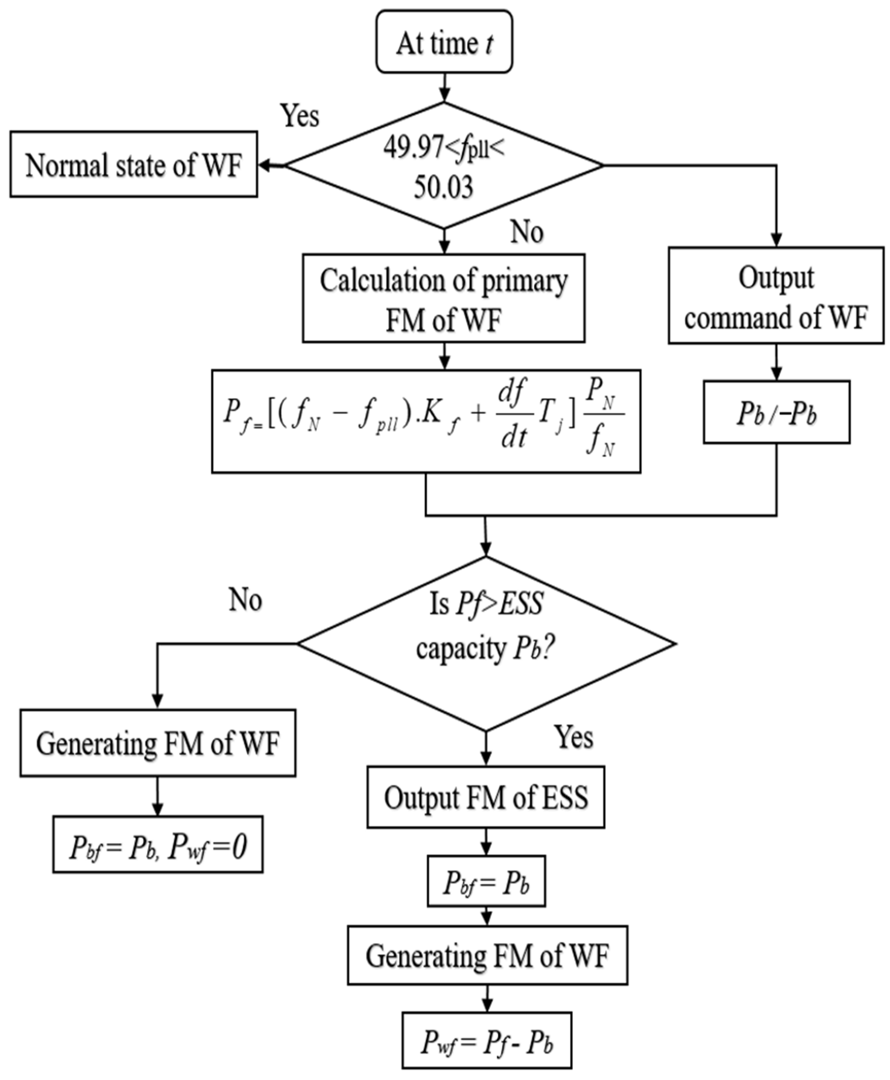
The optimized control strategy of coordinated FM of wind energy storage is presented in Figure 4. For the output FM power ( P f ) of the whole wind resource, the field is calculated and then allocated to the energy storage and wind. According to the principle of energy storage priority in distribution, if the energy storage capacity is greater than the FM power output required by the whole wind field, the FM task will be undertaken by the energy storage. If the energy storage capacity is less than the FM power output required by the whole wind field, the energy storage will be full, and the remaining FM task is undertaken by the wind. The calculation of the P f regards the entire wind farm output needs, and then allocate it to energy storage and wind turbines. The allocation is based on the principle of energy storage priority, as in the energy storage capacity has to be greater than the FM power that the entire wind farm needs to output. The FM task is undertaken by energy storage; if the energy storage capacity is less than the FM power, the entire wind farm needs the output and the full energy storage, while the remaining frequency adjustment tasks are undertaken by the wind. The energy storage capacity optimization and configuration are depicted in Figure 5.
In these figures, Pbf is the FM power of the energy storage system; Pf is the FM power of the wind field; Pwf is the FM power of the wind turbine; Pbref is the given power value; T is the FM duration of the wind; P b is the energy storage capacity; N f is the rated frequency of the system; d f p l l d t is the collected system frequency; dfpll/dt is the rate of change in system frequency; and T j and K f are the inertial time constant and active power FM coefficient of the synchronverter, respectively.

3.3. Optimal Economic Capacity

The life cycle cost of the ESS can reflect the average cost of the energy storage power station during the life cycle. The investment cost mainly includes the investment cost in the early stage and the replacement cost of the later device. The operation and maintenance costs mainly include fixed operation and maintenance costs determined by PCS and variable operation and maintenance costs determined by ESS charging and discharging.
The ESS device cost is mainly composed of energy storage devices, power conversion systems, and some auxiliary equipment:
C s y s = C b a t + C p c s + C b o p
where Cbat is the energy storage device cost; Cpcs is the power conversion system cost; and Cbop is the auxiliary equipment cost.
The cost of energy storage device Cbat expressed as
C b a t = C E E r a t e d η
where Erated is the rated power of the ESS (kW.h); η is the conversion efficiency of the ESS (%); CE is the unit power price ($/(kW.h)); Prated is the rated power of the ESS (KW); and t is the discharge time (h) of the energy storage system.
The power conversion system cost is expressed as
C p c s = C P P r a t e d
where Cp is the unit power price of PCS ($/kW).
C b o p = C B E r a t e d
where CB is the unit electricity price of auxiliary equipment ($/(kW.h)).
C L C C = C ¯ r e p + C ¯ s y s + C P O M + C V O M
C ¯ s y s = ( C E E r a t e d η + C P P r a t e d + C B E r a t e d ) i ( 1 + i ) N ( 1 + i ) N 1
where i is the discount rate (%); and N is the project period (years).
When the project cycle is greater than the life cycle of the energy storage system, the ESS needs to replace equipment. PCS and auxiliary equipment generally have a service life of ten years.
C ¯ r e p = C E E r a t e d η β = 1 k ( 1 α ) β n ( 1 + i ) β n i ( 1 + i ) N ( 1 + i ) N 1
where Crep is the average annual reduction ratio of the cost of energy storage devices; k is the number of battery replacements, k = N/n − 1, and n is the battery life (years); β is the βth replacement of the battery in the energy storage system.
C V O M = C e = C e t D η P r a t e d
C P O M = C f P r a t e d
where Cf is the operation and maintenance cost per unit of power (USD/(kW·year)). Variable operation and maintenance costs mainly consider electricity cost, Ce (USD/year), whereas Ce_P is the average annual electricity cost of the ESS per unit of power (USD/(kW·year)).

4. Results and Discussion

4.1. Results

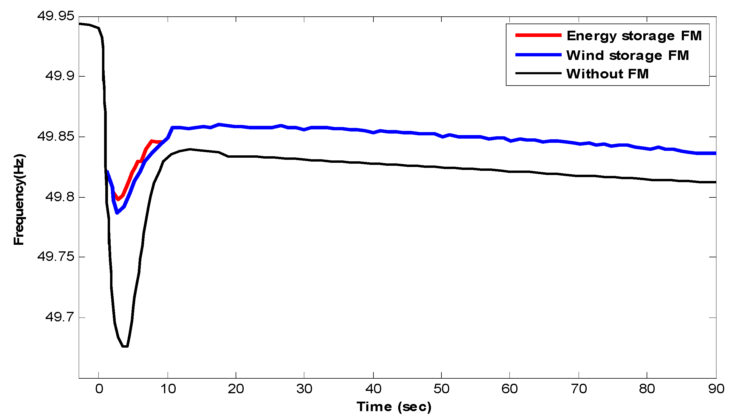
Figure 6 presents the wind storage coordination and FM control strategy based on the frequency outer loop of the energy storage compensation. Figure 6 depicts wind power does not participate in FM, but solely energy storage is used for frequency recovery. Where the grid has 20% wind power installed capacity, load disturbance is added, and the load takes up 5% of the system capacity. In Figure 6, the energy storage supports the FM control strategy of the wind farm, and the frequency of the system after stabilization is 49.878 Hz. The energy storage capacity that needs to be configured to restore the frequency to the stable value accounts for 8% of the wind field capacity. While this method is adopted, the lowest frequency of the system increases by 41% and the steady-state frequency increases by 20% compared with the wind farm without FM capacity.
An independent FM mode of energy storage is adopted and the original control strategy of wind energy storage to coordinate the FM by adding an appropriate amount of energy storage is presented in Figure 6. At the grid with 20% wind power installed, load disturbance of 5% system capacity is applied. Figure 7 depicts a wind speed of 8.6 m/s, the frequency characteristics of the system when solely the energy storage FM was adopted, and the original strategy of wind energy storage coordination FM. The FM effect is similar to that when the energy storage participates in the FM solely, and compared with wind energy storage, the frequency characteristics are greatly improved.
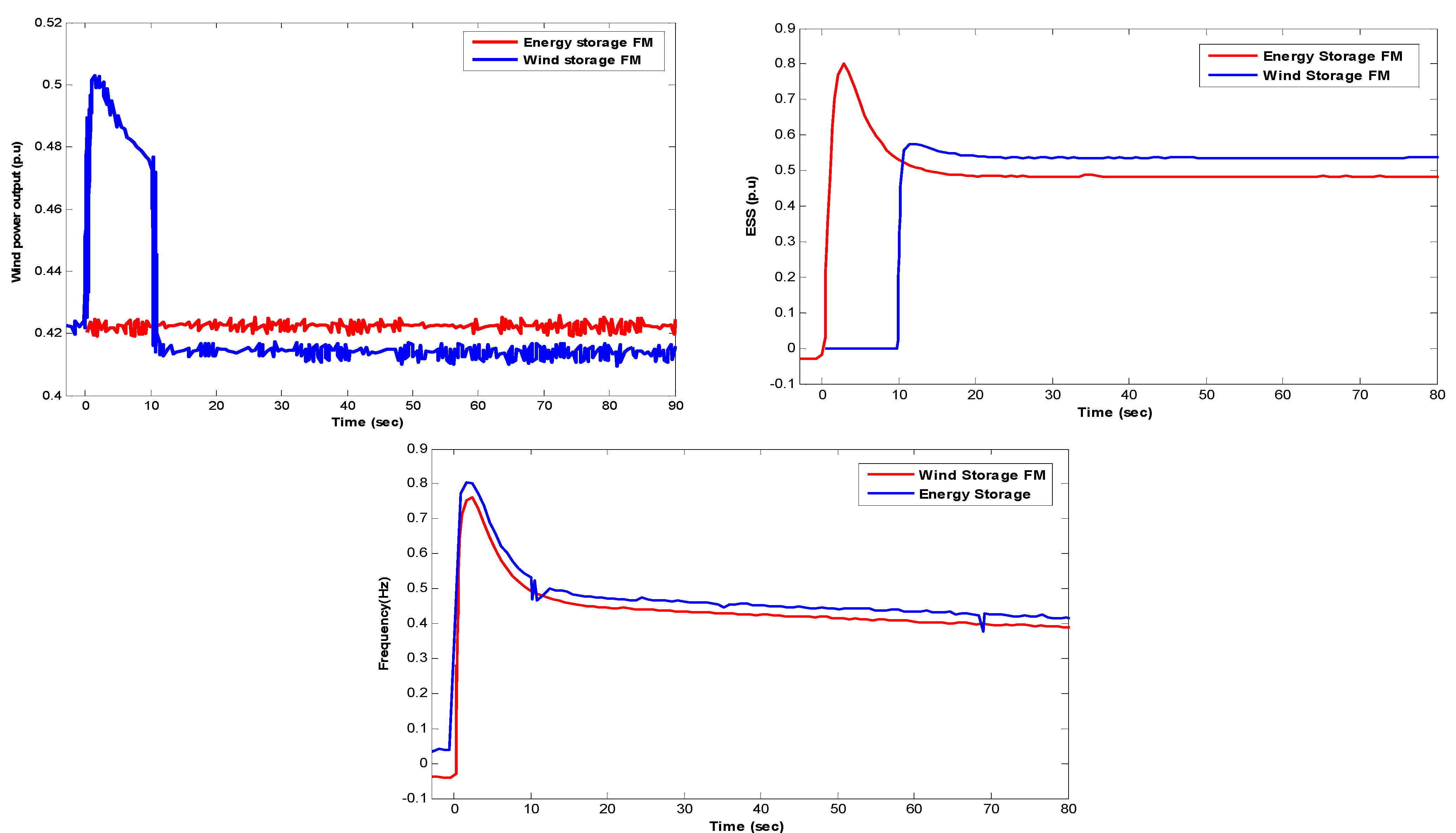
Figure 8 compares the output of the two control strategies of a single FM for energy storage and coordinated FM for wind storage. When the wind speed is 8.6 m/s, compared with the FM mode of wind energy storage, wind farms are supported when the original control strategy of wind storage coordinating FM is adopted. The energy storage output is found relatively smooth and the peak value of output is calculated smaller. Similarly, the total FM output of the wind and the energy storage participating system is the same under the two strategies. Under the condition that the FM effect is consistent, the energy storage alone support strategy is adopted and the energy storage capacity to be configured is 8% of the wind field capacity; thus, the energy storage capacity to be configured when the original control strategy of wind storage coordination and FM is adopted under 5.7% of the wind field capacity, which is 28% less than the energy storage alone support strategy.
When the wind speed of the wind is 11.2 m/s, the frequency characteristics of the system are consistent with those in Figure 9 when solely the energy storage FM is adopted, and with the original control strategy of the wind storage coordinated FM. Similarly, in the grid with 20% wind power installed capacity, load disturbance is added, and the load takes up 5% of the system capacity. In Figure 9, when the wind speed is 11.2 m/s, the energy storage capacity that needs to be configured is 13.9%, exceeding the capacity configuration (8%) when the energy storage supports wind farm FM. This is because, when the wind speeds are higher, the power drop amplitude after the wind exits the FM is observed to be more serious. Under a constant speed range, when the wind speed is high, the power drop range is observed to be deeper after the wind exits the FM, and the deeper the wind’s power has dropped, the more high-power energy storage needed to compensate. Therefore, under high wind speed, the short-time supporting power of the wind is larger. The original control strategy that energy storage solely compensates for power drop still needs to be optimized.
Figure 10 depicts the coordinated control strategy of wind power inertia release and steady-state support of energy storage requiring 5.9% energy storage. The wind speed is 11.2 m/s, at which it requires 8% of the energy storage phase for independent support compared with a reduction of 26%.

4.2. Discussion

The specific parameters of a lithium battery are given in Table 1. This strategy is adopted, and the energy storage capacity at high wind speeds is configured to be 5.9% of the installed capacity of the wind turbine. It is a reduction of 26% compared with the 8% capacity required for independent support of energy storage and improves the economics of energy storage participating in primary frequency regulation. Considering the battery’s development and commercial conditions, this study selects lithium batteries for capacity configuration. The lithium batteries have a strong ability to withstand high power and extreme temperatures and need not consume water resources in the production process. On the other hand, the service life, cost, energy storage, and mass production conditions of lithium batteries are relative to other batteries. There are fewer restrictions, making them widely used in commerce. Considering these two aspects comprehensively, the lithium battery is used for analysis.
Table 2 represents the wind storage coordination strategy’s energy storage capacity requirements under different wind speeds. Energy storage gets similar, supporting 8% under 6.2 m/s and 8.6% at 11.2 m/s wind speeds, while optimized and original strategies get different values under various wind speeds. The synchronverter of wind power has an energy reserve to participate in the primary FM of the grid; but, when the FM exits and the speed is restored, it causes the second drop in the grid frequency and deteriorates the system frequency dynamics. To improve the secondary frequency drop problem based on the comprehensive speed recovery strategy, the parameters of the FM support strategy are optimized, but the secondary frequency drop was not eliminated. To eliminate the secondary frequency drop, an ESS is added to the power generation side to cooperate with wind power generating units and traditional generating units to participate in grid frequency adjustment to maintain the grid frequency in a stable state. When a similar FM effect is achieved, the coordinated and optimized control strategy of wind power inertia release and energy storage steady-state support is the optimal strategy for wind storage coordinated FM.
The design method of the same rated power and capacity the operating performance of the ESS and meeting the FM are the constraints. The ESS has the lowest average annual cost per unit of power to obtain greater benefits for capacity allocation. The obtained control parameters, FM effect evaluation index, economic evaluation index, rated power Prated and rated capacity Erated are shown in Table 3. According to the maximum frequency deviation of the grid and considering the operating performance of the energy storage system. The rated power Prated of the ESS is determined by optimizing the control parameters of the energy storage system and the rated capacity Erated of the ESS is determined according to the state of charge (SOC) of the ESS. Meanwhile, the average annual cost per unit power of the ESS CLCC is calculated according to the life cycle cost model. The capacity configuration is based on the minimum primary FM effect J as the optimization objective.

5. Conclusions

This study discussed the characteristics of FM and configured the wind energy storage capacity by optimizing the controlling parameters. The main conclusions are as follows:
  • One can improve the economics of energy storage by determining the design method of its rated power and the capacity according to the FM requirements.
  • The energy storage capacity under high wind speeds is configured to be 5.9% of the installed capacity, which is a reduction of 26% compared with the 8% capacity required for independent support of energy storage.
  • The comprehensive optimal energy storage capacity configuration of the coordinated FM control strategy is improved.
In a follow-up study, the coordinated control of the three generators and the coordinated FM of the wind storage and synchronous generators still need to be studied. In addition, comprehensive consideration is needed to ascertain the various factors that affect system resonance.

Author Contributions

Conceptualization, writing—original draft preparation, formal analysis, W.C., M.S.N. and A.N.A.; methodology, investigation, M.S.N., A.N.A., M.S.B., M.A.M. and W.C.; review and editing, B.L., Z.D., M.A.M. and M.G. All authors have read and agreed to the published version of the manuscript.

Funding

This research did not receive any direct funding.

Institutional Review Board Statement

Not applicable.

Informed Consent Statement

Not applicable.

Data Availability Statement

Not applicable.

Acknowledgments

The authors are highly grateful to their affiliated universities and institutes for providing research facilities.

Conflicts of Interest

The authors declare no conflict of interest.

Abbreviations

FMFrequency modulation
ESSEnergy storage system
SOCState of charge
P f FM power
N f   Rated frequency of the system
PwfPower of the wind turbine
K f   Inertial time constant
P b   Energy storage capacity
CbatEnergy storage device cost
CpcsPower conversion system cost
CbopAuxiliary equipment cost
EratedRated power of the ESS
CBUnit electricity price
CfOperation and maintenance cost
JOptimization objective

References

  1. Ramírez, M.; Castellanos, R.; Calderón, G.; Malik, O. Placement and sizing of battery energy storage for primary frequency control in an isolated section of the Mexican power system. Electr. Power Syst. Res. 2018, 160, 142–150. [Google Scholar]
  2. Bhutta, M.S.; Sarfraz, M.; Ivascu, L.; Li, H.; Rasool, G.; ul Abidin Jaffri, Z.; Farooq, U.; Ali Shaikh, J.; Nazir, M.S. Voltage Stability Index Using New Single-Port Equivalent Based on Component Peculiarity and Sensitivity Persistence. Processes 2021, 9, 1849. [Google Scholar]
  3. Rahman, F.S.; Kerdphol, T.; Watanabe, M.; Mitani, Y. Optimization of virtual inertia considering system frequency protection scheme. Electr. Power Syst. Res. 2019, 170, 294–302. [Google Scholar]
  4. El-Bidairi, K.S.; Nguyen, H.D.; Mahmoud, T.S.; Jayasinghe, S.; Guerrero, J.M. Optimal sizing of Battery Energy Storage Systems for dynamic frequency control in an islanded microgrid: A case study of Flinders Island, Australia. Energy 2020, 195, 117059. [Google Scholar]
  5. Belila, A.; Amirat, Y.; Benbouzid, M.; Berkouk, E.M.; Yao, G. Virtual synchronous generators for voltage synchronisation of a hybrid PV-diesel power system. Int. J. Electr. Power Energy Syst. 2020, 117, 1056776. [Google Scholar]
  6. Zhu, T.; Nazir, M.S.; Ali Mokhtarzadeh, A.; Abdalla, A.N.; Nazir, H.M.; Chen, W. Improve performance of induction motor drive using weighting factor approach-based gravitational search algorithm. Int. J. Electron. 2022, 109, 900–913. [Google Scholar]
  7. Nazir, M.S.; Abdalla, A.N.; MMetwally, A.S.; Imran, M.; Bocchetta, P.; Javed, M.S. Cryogenic-Energy-Storage-Based Optimized Green Growth of an Integrated and Sustainable Energy System. Sustainability 2022, 14, 5301. [Google Scholar]
  8. Abdalla, A.N.; Nazir, M.S.; Tao, H.; Cao, S.; Ji, R.; Jiang, M.; Yao, L. Integration of energy storage system and renewable energy sources based on artificial intelligence: An overview. J. Energy Storage 2021, 40, 102811. [Google Scholar]
  9. Das, C.K.; Mahmoud, T.S.; Bass, O.; Muyeen, S.; Kothapalli, G.; Baniasadi, A.; Mousavi, N. Optimal sizing of a utility-scale energy storage system in transmission networks to improve frequency response. J. Energy Storage 2020, 29, 101315. [Google Scholar]
  10. Nazir, M.S.; Abdalla, A.N.; Sohail, H.M.; Tang, Y.; Rashed, G.I.; Chen, W. Optimal planning and investment of Multi-renewable power generation and energy storage system capacity. J. Electr. Syst. 2021, 17, 171–181. [Google Scholar]
  11. Soni, N.; Doolla, S.; Chandorkar, M.C. Improvement of transient response in microgrids using virtual inertia. IEEE Trans. Power Deliv. 2013, 28, 1830–1838. [Google Scholar]
  12. D’Arco, S.; Suul, J.A.; Fosso, O.B. A virtual synchronous machine implementation for distributed control of power converters in smartgrids. Electr. Power Syst. Res. 2015, 122, 180–197. [Google Scholar]
  13. Sakimoto, K.; Miura, Y.; Ise, T. Stabilization of a power system including inverter type distributed generators by the virtual synchronous generator. IEEJ Trans. Power Energy 2012, 132, 341–349. [Google Scholar]
  14. Alipoor, J.; Miura, Y.; Ise, T. Power system stabilization using virtual synchronous generator with alternating moment of inertia. IEEE J. Emerg. Sel. Top. Power Electron. 2015, 3, 451–458. [Google Scholar]
  15. Jongudomkarn, J.; Liu, J.; Ise, T. Comparison of current-limiting strategies of virtual synchronous generator control during fault ride-through. IFAC-Pap. Line 2018, 51, 256–261. [Google Scholar]
  16. Hirase, Y.; Abe, K.; Sugimoto, K.; Shindo, Y. A grid-connected inverter with virtual synchronous generator model of algebraic type. Electr. Eng. Jpn. 2013, 184, 10–21. [Google Scholar]
  17. Guerrero, J.M.; Vasquez, J.C.; Matas, J.; de Vicuna, L.G.; Castilla, M. Hierarchical control of droop-controlled ac and dc microgrids-a general approach toward standardization. IEEE Trans. Ind. Electron. 2011, 58, 158–172. [Google Scholar]
  18. Liu, J.; Miura, Y.; Bevrani, H.; Ise, T. Enhanced virtual synchronous generator control for parallel inverters in microgrids. IEEE Trans. Smart Grid. 2015, 8, 2268–2277. [Google Scholar]
  19. Tamrakar, U.; Galipeau, D.; Tonkoski, R.; Tamrakar, I. Improving transient stability of photovoltaic-hydro microgrids using virtual synchronous machines. In Proceedings of the 2015 IEEE Eindhoven Power Tech, Eindhoven, The Netherlands, 29 June–2 July 2015; pp. 1–6. [Google Scholar]
  20. Onaolapo, A.K.; Carpanen, R.P.; Dorrell, D.G.; Ojo, E.E. Reliability Evaluation and Financial Viability of an Electricity Power Micro-Grid System with the Incorporation of Renewable Energy Sources and Energy Storage: Case Study of KwaZulu-Natal, South Africa. IEEE Access 2021, 9, 159908–159924. [Google Scholar]
  21. Kerdphol, T.; Rahman, F.S.; Watanabe, M.; Mitani, Y. Optimization of Virtual Inertia Control Considering System Frequency Protection Scheme. In Virtual Inertia Synthesis and Control; Springer: Berlin/Heidelberg, Germany, 2021; pp. 227–247. [Google Scholar]
  22. Chen, J.; Jin, T.; Mohamed, M.A.; Annuk, A.; Dampage, U. Investigating the Impact of Wind Power Integration on Damping Characteristics of Low Frequency Oscillations in Power Systems. Sustainability 2022, 14, 3841. [Google Scholar]
  23. Nazir, M.S.; Abdalla, A.N.; Zhao, H.; Chu, Z.; Nazir, H.M.J.; Bhutta, M.S.; Javed, M.S.; Sanjeevikumar, P. Optimized economic operation of energy storage integration using improved gravitational search algorithm and dual stage optimization. J. Energy Storage 2022, 50, 104591. [Google Scholar]
  24. Al-Ghussain, L.; Ahmad, A.D.; Abubaker, A.M.; Mohamed, M.A. An integrated photovoltaic/wind/biomass and hybrid energy storage systems towards 100% renewable energy microgrids in university campuses. Sustain. Energy Technol. Assess. 2021, 46, 101273. [Google Scholar]
  25. Meng, L.; Zafar, J.; Khadem, S.K.; Collinson, A.; Murchie, K.C.; Coffele, F.; Burt, G.M. Fast frequency response from energy storage systems—A review of grid standards, projects and technical issues. IEEE Trans. Smart Grid. 2019, 11, 1566–1581. [Google Scholar]
  26. Judge, P.D.; Green, T.C. Modular multilevel converter with partially rated integrated energy storage suitable for frequency support and ancillary service provision. IEEE Trans. Power Deliv. 2018, 34, 208–219. [Google Scholar]
  27. Arifin, Z.; Firmanto, A. Battery Energy Storage System as Frequency Control at Substation based on Defense Scheme Mechanism. In Proceedings of the 2021 International Seminar on Intelligent Technology and Its Applications (ISITIA), Surabaya, Indonesia, 21–22 July 2021. [Google Scholar]
  28. Alsiraji, H.A.; El-Shatshat, R. Comprehensive assessment of virtual synchronous machine based voltage source converter controllers. IET Gener. Transm. Distrib. 2017, 11, 1762–1769. [Google Scholar]
  29. Vargas, R.Z.; Lopes, J.C.; Colque, J.C.; Azcue, J.L.; Sousa, T. Energy Storage System Integration with Wind Generation for Primary Frequency Support in the Distribution Grid. Simpósio Bras. Sist. Elétricos-SBSE 2020. [Google Scholar] [CrossRef]
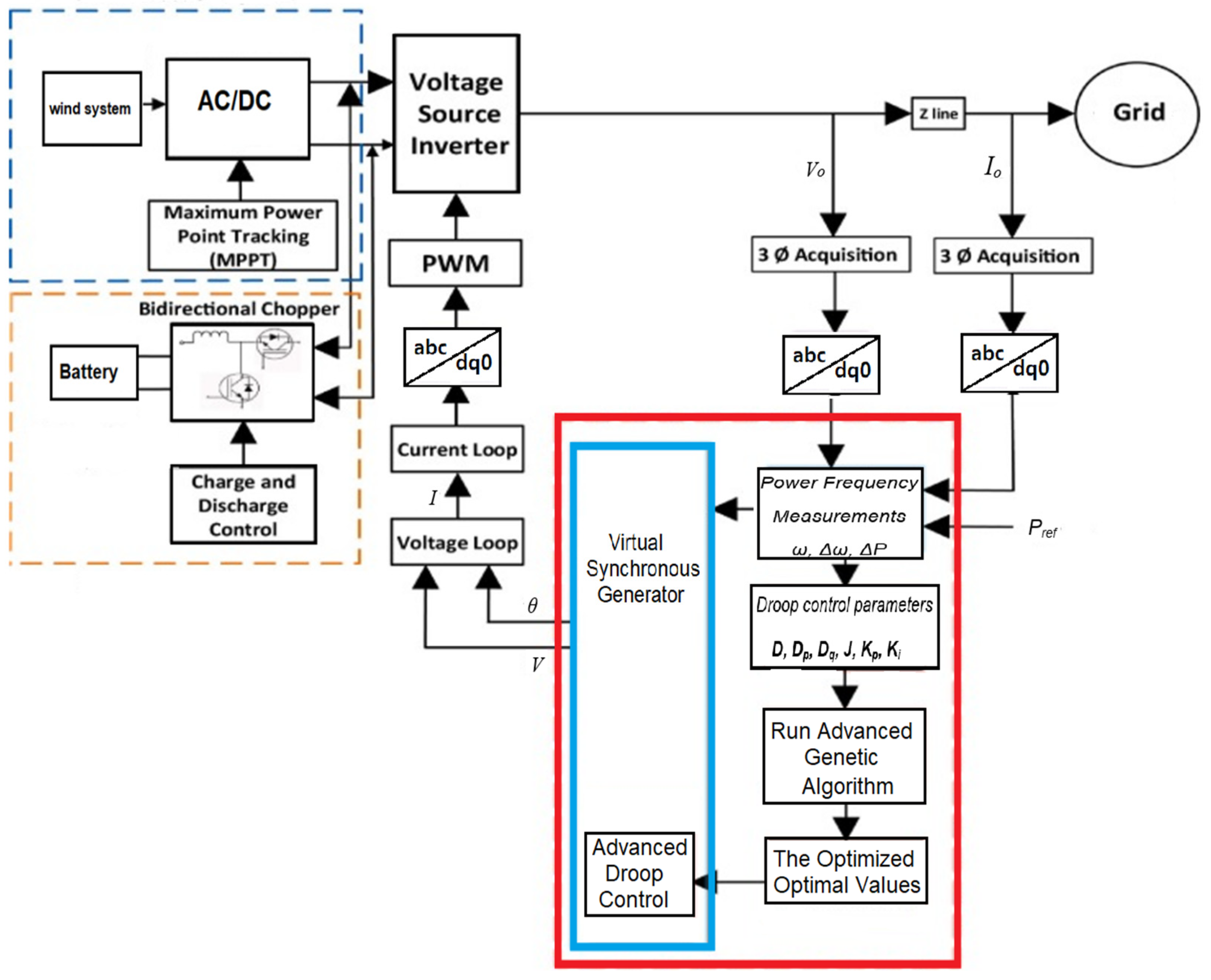
Figure 1. The simple structure of the synchronverter-based wind energy storage system.
Sustainability 14 08510 g001
Figure 2. Proposed dual-loop control strategy.
Sustainability 14 08510 g002
Figure 3. Simulation model of the proposed system.
Sustainability 14 08510 g003
Figure 4. Optimization control strategy.
Sustainability 14 08510 g004
Figure 5. Energy storage capacity optimization and configuration.
Sustainability 14 08510 g005
Figure 6. FM control strategy of the wind farm supported by energy storage.
Sustainability 14 08510 g006
Figure 7. The FM effect of the original strategy of wind energy storage coordination control.
Sustainability 14 08510 g007
Figure 8. Comparison of the output of the original control strategy of the FM coordination energy storage and wind energy storage.
Sustainability 14 08510 g008
Figure 9. FM effect of the original control strategy for wind storage coordination.
Sustainability 14 08510 g009
Figure 10. Energy storage compensation steady-state strategy under a 11.2 m/s wind speed.
Sustainability 14 08510 g010
Table 1. Energy storage cost analysis.
Type of BatteryUnit Capacity Price CE (USD/kW·h)Unit Power Price Cp (USD/kW)O&M Cost Cf (USD)/(kW·h)Charging Electricity Price Cc (USD/kW.h)Conversion Efficiency (%)Life Time Period (Year)
Lithium battery21,600727010403.50.8510
Table 2. Energy storage capacity requirements under different wind speeds.
Wind Speed6.2 m/s8.6 m/s11.2 m/s
With energy storage supports8%8%8%
Original strategy: secondary fall compensation6.7%5.6%13.9%
Optimization strategy: energy storage and compensation5.5%5.2%5.9%
Table 3. Capacity allocation is based on the robust economic model, comprehensive optimal capacity allocation and control variable.
ModelParameterValue
Robust economic modelControl variable (Tj)4
Control variable (Kf)5
Economic evaluation index (J)0.131
Economic evaluation index (CLCC) (103 USD)66.30
Power (%)1.4
Optimal capacity allocationControl variable (Tj)8
Control variable (Kf)13
Economic evaluation index (J)0.098
Economic evaluation index (CLCC) (103)150
Power (%)3.7
Control variableControl variable (Tj)12
Control variable (Kf)20
Economic evaluation index (J)0.096
Economic evaluation index (CLCC) (103)23,200
Power (%)5.9
Publisher’s Note: MDPI stays neutral with regard to jurisdictional claims in published maps and institutional affiliations.