Article

Design Methodology and Analysis of Five-Level LLC Resonant Converter for Battery Chargers

1
School of Electrical and Electronic Engineering, Universiti Sains Malaysia, Nibong Tebal 14300, Penang, Malaysia
2
British Malaysian Institute, Universiti Kuala Lumpur, Kuala Lumpur 50250, Malaysia
*
Authors to whom correspondence should be addressed.
Sustainability 2022, 14(14), 8255; https://doi.org/10.3390/su14148255
Submission received: 12 May 2022 / Revised: 15 June 2022 / Accepted: 30 June 2022 / Published: 6 July 2022
(This article belongs to the Section Energy Sustainability)

Abstract

:
This paper presents proposal of a five-level LLC resonant DC–DC converter design procedure for battery chargers. The five-level inverter side of the proposed converter is connected to a transform-less LLC resonant tank to ensure operating at high frequency and achieve soft switching. The proposed converter has less weight, size, and cost. It is also much simpler in terms of implementation, and has smooth energy conversion to the load. The proposed converter is designed to work within the range close to the resonant frequency, to ensure higher power density and efficiency. Thus, the range of operating frequency is set to be (91 kHz < fsw < 110 kHz), while the LLC parameters is designed to achieve resonant frequency fr = 100 kHz. Therefore, it is designed to achieve zero voltage switching (ZVS) for all switches, which enhances the efficiency as well. The theoretical analysis outcomes were confirmed by simulation studies conducted using MATLAB/SIMULINK. An experimental model was also developed and validated with 100 VDC input voltage, which delivered output power of 100 W, 48 V, with efficiency around 96.9%. Selected findings are presented to confirm the effectiveness of the suggested converter.

1. Introduction

With technological advancements in recent years, greenhouse gas emissions have increased, resulting in climate change and global warming. The energy technology sector is heavily reliant on fossil fuels and cannot cope with the current stringent emission requirement. As a result, green energy has become a central component of major economic policies and a major focus in international politics. Therefore, a converter is needed to convert the voltage before it can be effectively used [1]. Because of the negative effects of electricity generation from fossil sources, it is vital to switch to clean and renewable energy sources like solar, geothermal, wind, and hydropower energy [2]. The energy that reaches the Earth per hour from the Sun is close to the total energy consumed by humanity in a year [3]. As a result, utilizing this readily available resource should eventually reduce reliance on conventional fossil energy sources and contribute to decline in global warming, for a cleaner and safer world [2]. Energy storage systems (ESS) are mostly used to ensure the suitability of renewable energy generation in all circumstances.
Additional issues could also arise from the interconnection/linkage of renewable energy sources such as solar, wind, and fuel cells [4]. Scholars have developed highly efficient applications for energy conversion, owing to the recent improvements in power electronics technology. Power inverters are required for AC drives and other grid applications. Even though a traditional two-level inverter has been utilized in industry, it has significant power quality issues [5].
In recent years, battery charging technologies based on DC–DC topologies have garnered attention due to their high equalization accuracy and high efficiency [6]. The use of batteries to store energy is recognized as one of the most significant and efficient methods for maintaining a consistent energy supply [7]. In power applications, two major battery technologies are commonly used: lead–acid and lithium-ion (Li-ion). Monitoring battery functioning and assessing battery aging in real-world applications has been a difficult objective involving a variety of complex processes under complex operating settings [8,9,10,11]. Resonant inverters have received considerable attention in power electronics research and have been implemented in a vast array of industrial applications. The use of resonant inverters has also been reported in power conversion systems [12], induction heating [13], telecommunication and wireless power transfer [14], energy storage systems [15], and ozone generators [16]. A resonant inverter can be made using either the series resonant tank (RT), parallel RT, or series-parallel RT [17]. Conventionally, resonant converters are made using either half-bridge topology or full-bridge topology [12].
Multilevel inverters (MLIs) are not famous for high-frequency resonant inverters due to the difficulty of their modeling for control design, particularly when using high-frequency switching modulation approaches. Comparatively, single-phase MLIs are becoming increasingly preferred in power generation systems. Proposals have also been made for novel MLI topologies to solve the issues of traditional inverters and achieve better power quality and high efficiency [18]. Much attention has been given to MLIs due to their high-quality output waveforms and minimal dv/dt stress. Their output waveform is characterized by low total harmonic distortion (THD) because of the increase in the number of the inverter’s output voltage level, which reduces the output filter’s size. MLIs contain multiple DC voltage supplies, capacitors, power diodes, and switches, as well as driver circuits, to achieve sufficient output voltage with an appropriate switching pattern [5,19]. MLIs have been shown to be a viable technology for numerous applications, including commercial and customized products, renewable energy generation (REG), high-voltage direct current (HVDC) transmission, adjustable speed drives (ASD), flexible ac transmission systems (FACTS), battery energy storage systems (BESS), custom power devices (CPD), active frontend converters (AFC), and electric vehicles (EV) [20]. Among all these, diode clamped or neutral-point (DCML), flying capacitor (FCML), and cascade H-bridge (CHB) remain the most common MLI topologies; thus they are called “Traditional MLIs” [2,21].
One of the most interesting and fascinating methods for compensating the volatility of electric supply is by using cascaded multilevel converter (MLC) based battery energy storage system (BESS) that comprises of CHB inverters [22]. The ability of the cascaded multilevel converter to utilize lower-voltage semiconductor switches makes it one of the most suitable topologies for BESS. It lowers the THD and offers higher modularity compared to a typical inverter, thus contributing to a simpler voltage-scaling setup [23]. BESS, which is based on a three-phase CHB multilevel converter and uses lithium–ion batteries, was first proposed by [22]. By utilizing cascaded H-bridge inverters, BESS was found able to achieve positive performance operation while charging and discharging.
MLC has been suggested for high-voltage power conversion to lessen the voltage stress on switching devices [24,25,26]. A five-level cascaded MLC using simple battery charging method and battery charging equalization was proposed in [27]; the cascaded MLC was supplied with two levels of dc voltage sources which can be obtained from batteries for electrical vehicle. For electrical vehicles, a cascaded H-bridges inverter can be employed to drive the traction motor from battery banks. Additionally, the use of a cascade inverter enables the EV drive to continue operating even if one level of the inverter system fails [28]. Reference [29] proposed a light electric car fast charger that consists of a supercapacitor and lithium-ion battery (LIB), as well as an AC/DC rectifier, light electric vehicle (LEV) battery, and full-bridge LLC resonant converter. In the ZVS region, the research recommended a fast-charging method based on a soft-switched LLC resonant converter. Decreasing use of lead–acid batteries in the past due to environmental concerns has driven the proposal for new LEV systems with fast charging methods that use an 800 Watt-hour W/h LIB and a 50 W/h supercapacitor. Constant voltage (CV), constant current (CC) and CC-CV mode algorithms are commonly used in fast-charging systems. The constant voltage applied to the battery is controlled using the CV technique. The CC mode differs from the CV mode in that it controls the constant current supplied to the battery [29]. Constant current (CC) and constant voltage (CV) charging strategies have been widely used to charge lithium-ion batteries with great success. Battery chargers must be able to operate over a wide output voltage range based on the charging profile. LLC resonant converters are used in battery charger applications because of their soft switching and high frequency operation potentials [30].
A modulation technique for a full-bridge three-level LLC resonant converter was proposed in [15]. The researcher employed a variable duty cycle which could run at a specific frequency. A parameter called “master duty” was introduced for setting each voltage-level duty and for seamless handling of two-level, three-level, and mixed modes. LLC converter is a widely used topology among the numerous topologies of DC–DC converter because of its benefits, which include the ability of each main switch to achieve zero-voltage switching (ZVS) from zero to full load without the need for an auxiliary circuit, the ability of the rectifier diodes to achieve zero-current switching (ZCS), low electromagnetic interference (EMI) emissions, high efficiency, a wide operating range, and high power density capability [31]. The researcher also analyzed the wide-adjustable-range LLC resonant converter used in lithium-ion battery LIB charger of a plug-in hybrid EV system PHEV [31]. Different scholars [32,33,34,35,36] have also proposed a hybrid of LLC converter with a three-level conversion approach. MLIs are used to alleviate voltage stress experienced by switching devices; they are also used to increase the power range of LLC resonant converter as reported by [37,38]. Furthermore, researchers have proposed a technique that combines LLC converter with a five-level conversion topology [39].
As mentioned earlier, the conventional topologies for realizing resonant converters are half-bridge and full-bridge, and multilevel inverters are not favorable for high-frequency resonant inverters since modelling them for control design is difficult, particularly when using high-frequency switching modulation approaches. To eliminate the drawbacks associated with half-bridge [6], full-bridge [40], phase-shifted full-bridge [41], and three-level [36] inverters integrated with resonant tank network, a five level multilevel inverter is introduced in this paper.
This paper presents a five-level cascaded multilevel non-isolated LLC resonant tank DC–DC converter for battery charger application for electrical vehicle. This converter integrates the advantages of the LLC resonant converter, non-isolation, and the five-level conversion technique. The resonant network is fed by a high-frequency converter working at a proper operating frequency by applying frequency modulation control. Furthermore, the transformer-less approach adopted in this work minimizes the system’s cost and weight. The validity of the proposed converter has been verified, supported by theoretical analysis, simulation results, and an experimental prototype. The design is described in detail in the next section. The selected operation range, gain, and ZVS achievement had been carefully estimated to ensure the converter able to operate with a range close to the resonant frequency, to achieve ZVS for all switches, high power density, and high efficiency. The rest of this article is presented as follows: the proposed circuit layout of the converter and its essential characteristics are described in Section 2, while Section 3 presents the explanation of the various operating modes. Section 4 explains the design consideration of the equivalent circuit, while Section 5 presents the simulation results. Section 6 presents the results of the experiments using a 100 W scaled laboratory prototype, while Section 7 concludes this paper. Finally, future challenges are introduced in Section 8.

2. Proposed Topology

Figure 1 illustrates the complete configuration of the five-level inductor-inductor-capacitor (LLC) resonant DC–DC converter. The circuit comprises of two separate direct current DC sources: each source is linked to H bridge and eight IGBTs. The LLC circuit is composed of an inductor (Lr), a capacitance (Cr), an inductance (Lm) in parallel, and a full-wave rectifier with a filter capacitor and a battery at the converter’s output side, respectively. The switch pairs S1, S2 and S3, S4 operate in a complementary fashion and the same is true for S5, S6, S7, S8. In contrast to conventional single-stage converters, the voltage delivered to the LLC stage contains five discrete levels (see Figure 2). The key steady-state waveforms of the converter are shown in Figure 3. Summing Vin1 = Vin2 = Vdc condition, the five-level inverter can generate five output voltage (VAB) levels: +Vdc, +2Vdc, 0, −Vdc, and −2Vdc, as shown in the equivalent circuits presented in Figure 4. This paper focuses on the issue of charging the battery by CV method by MLI integrated with resonant converter and a transformer-less. The operation modes of the proposed approach are outlined in the next section.

3. Modes of Operation

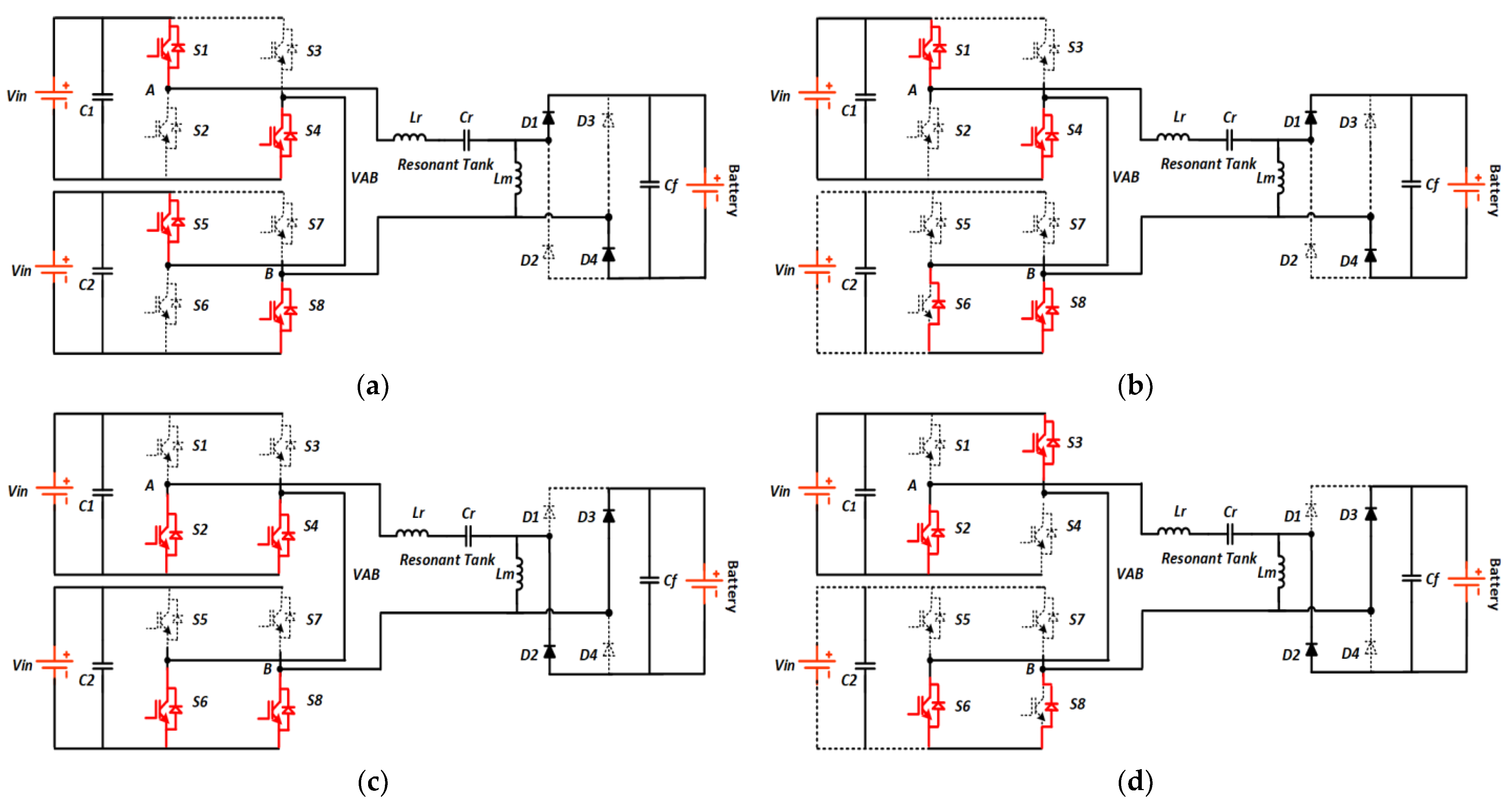
Based on Figure 4, the operation of the converter can be explained utilizing the transition states, which consists of five modes, as will be discussed in the following sub-sections. The different operational modes of the proposed converter are presented in Figure 4.

3.1. Mode1 (t0 < t < t1)

In this mode, switches in both bridges act in complementary approach; switches S1 and S4 in the first bridge are turned ON, whereas S5 and S8 in the second bridge are OFF. At this time, VAB reaches the maximum positive voltage +2Vdc, and the resonant capacitor decreases and starts to change its polarity (zero crossing) from positive to negative polarity, while the resonant current, iLr, stops decreasing. The rectifier diodes D1 and D4 are conducted. Figure 4a depicts this mode of operation.

3.2. Mode2 (t1 < t < t2)

The first step of this mode is to turn OFF switch S5, while leaving switches S1, S4 and S8 ON. In this mode, the current completes its path through freewheeling diode of S6, VAB starts to drop, and the voltage across LLC is half of the input voltage (VAB = +Vdc). The polarity of iLr begins to shift from negative to positive polarity (zero crossing). The energy stored in the resonant tank is transferred to the battery through the rectifier diodes D1 and D4. Figure 4b shows this mode of operation.

3.3. Mode3 (t2 < t < t3)

In this mode, S1 and S4 are turned OFF, while S2, S4, S6, and S8 are turned ON. VAB drops to zero, and the voltage across LLC is zero (VAB = 0) in this mode. The resonant capacitor voltage Vcr stops decreasing, and starts to rise in order to change polarity, whereas the resonant current iLr increases. Rectifier Diodes D2 and D3 are conducted and their current is increasing. Figure 4c represents this mode of operation.

3.4. Mode4 (t3 < t < t4)

In the previous stage, the positive half cycle is completed. In this mode, switches S2, S3, and S6 are switched ON and the freewheeling diode of S8 is conducted (see Figure 4d). VAB has negative polarity and the voltage across LLC is half the negative input voltage (VAB = −Vdc) in this mode. iLr reaches the maximum value and stops increasing, while resonant capacitor voltage Vcr reaches the positive polarity. Rectifier diode D2 and D3 are still conducted and their current is at the maximum value, as the energy stored in the resonant tank is transferred to the battery through them.

3.5. Mode5 (t4 < t < t5)

Figure 4e shows the mode between t4 and t5. In this mode, switches S2, S3, and S6 are still ON, and S7 will operate. Resonant capacitor voltage Vcr increases, and on the way, reaches its highest point (fully charged), whereas the resonant inductor current iLr begins to reduce. VAB drops to negative 2Vdc and this voltage goes to the LLC resonant tank. At the end of the previous stage, the rectifier diodes D1 and D4 are still switched OFF, thus, the energy stored in the resonant tank is transferred through rectifier diodes D2 and D3.

4. Design Consideration

The best efficiency may be reached by LLC resonant converters when the resonant frequency matches the switching frequency. The design strategy for resonant elements is centered on obtaining the optimal operating point, which can be accomplished in the same manner as with a typical LLC converter, as detailed in various publications [42,43]. The parameters of the proposed converter are explained in this section based on the specifications presented in Table 1.
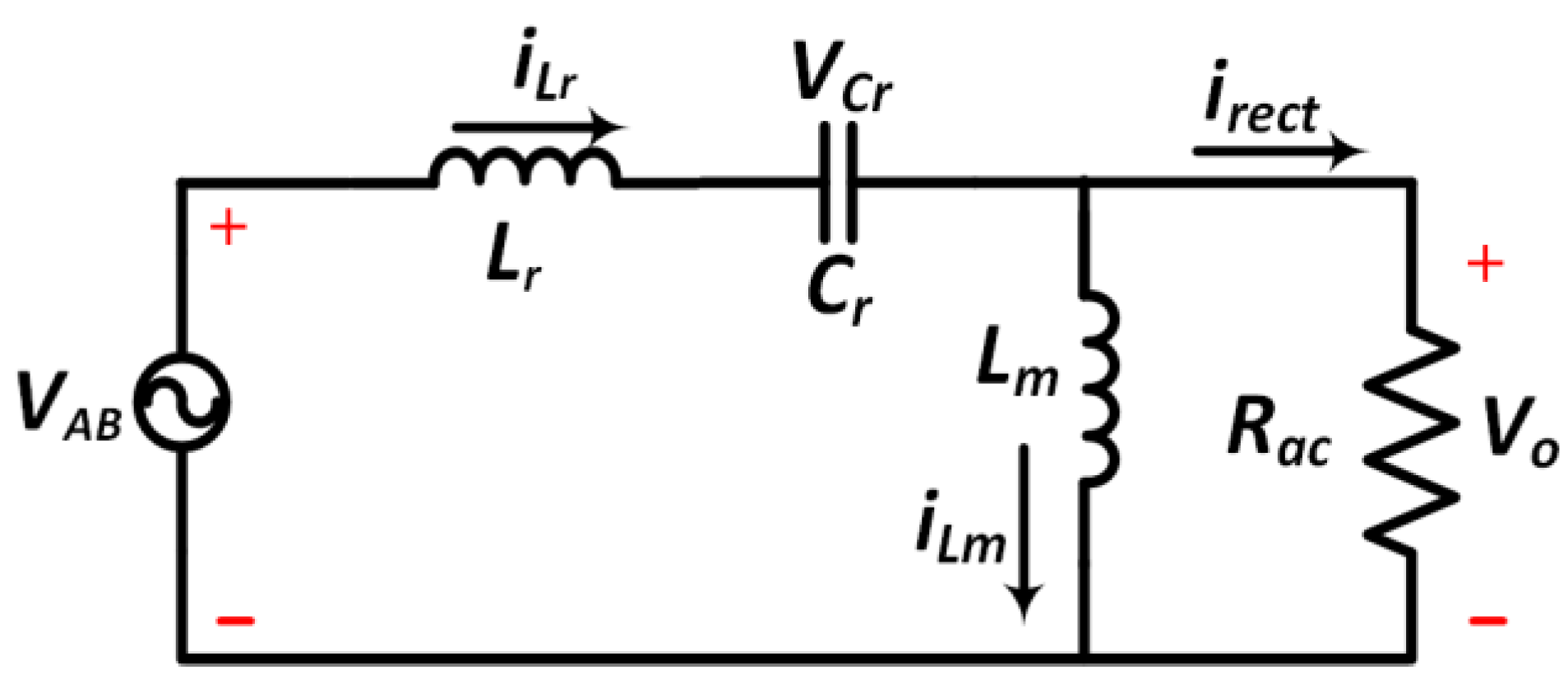
Because the resonant tank acts as a bandpass filter, it is typical to assume that the power transmission is limited to the core components of the voltages and currents in the resonant tank. This is referred to as the first harmonic approximation (FHA). The voltage gain (Mgain) of the LLC stage can be calculated using the analogous circuit depiction in Figure 5.
M gain = V b a t V i n = F n 2 × L n 1 ( L n × F n 2 1 ) 2 + F n 2 × ( F n 2 1 ) 2 × ( L n 1 ) 2 × Q 2
where Ln is the ratio of the magnetizing inductance Lm to the resonant inductance Lr, defined as follows:
L n = L m L r
The definitions of the first and second resonant frequencies are as follows:
f r 1 = 1 2 π L r × C r  
f r 2 = 1 2 π L r + L m × C r
where Lr = resonant inductance, Cr = resonant capacitor, and Lm = magnetizing inductance.
The ratio of the switching frequency to the resonant frequency is the normalized switching frequency and is defined as follows:
F n = f s w f r 1
Q is the quality factor, and introduced to illustrate different load conditions. Q is defined to be the ratio between characteristic impedance and the load resistance, which is calculated as follows:
Q = L r C r R a c
R a c = 8 π 2 × n 2 × V b a t 2 P b a t
where Rac is equivalent to the load and rectifier stage. Vbat and Pbat denote the output voltage and power, respectively. Additionally, the output voltage is clamped by the battery and is considered the same while the charging is carried out.
Z o = L r C r   or   Q × R a c
The value Fn determines the switching frequency in relation to the higher resonance frequency of the resonant tank fr1. The resonant tank’s typical impedance is Zo. Variables Ln and Q are incorporated to make (1) independent of the actual Lm, Lr, and Cr values. Pbat represents the transferred power to the battery. The frequency fr2, at which the voltage gain Mgain is maximum, is the lower resonance frequency fr2. As shown in (1), it is used to plot the normalized dc gain against normalized frequency for various values of the quality factor (Q), as seen in Figure 6a, which depicts the voltage gain under various loading situations (changes in Q value) and varying designs (changes in Ln) as in Figure 6b at different relative switching frequencies.
The relationship between voltage gain, load, resonant and switching frequency frequencies is depicted by the curve. The optimum normalized gain value for the given inductor ratio is represented as a minimum and maximum gain value (dash lines).
Based on the operating points in Figure 6, the values of Ln and Q are chosen and used to compute the Lr and Cr values. The gain is calculated using the lower and maximum switching frequency values to check the range of the selected switching frequency. Q value must be 0.39 to achieve the necessary output voltage of 48 Vdc at a 100 kHz resonant frequency.

Calculation of Components in Resonant Tank Circuit

To construct the resonant tank circuit, Equations (2) and (6) are used to calculate the inductance ratio Ln and quality factor Q values. Plotting the voltage gain equation of the LLC resonant high-voltage DC–DC converter for multiple Ln and Q values, as illustrated in Figure 6a,b, is the simplest way to choose Ln and Q values. The graph aids in finding the Ln and Q values that will meet the converter’s gain requirement. As a result, the chosen values for Ln and Q are 3 and 0.39, respectively, depending on the desired gain. Having chosen the Ln and Q values, the sizes of LLC resonant tank components are then determined. To begin, the resonant capacitor Cr can be obtained using the formula:
C r = 1 2 π × f r × Q × R a c = 218.5   nF .
Following that, the value of the resonant inductor, Lr, can be estimated using:
L r = 1 ( 2 π × f r ) 2 × c r   or   Z o 2 × C r = 11.5   μ H .
Finally, using the normalised inductance, Ln, the value of the magnetising inductor, Lm, can be calculated as follows:
L m = L r × L n = 34.7   μ H .

5. Simulation Results

To validate the suggested converter, a lab model with 60–140 V input voltage and a 48 V/100 W output voltage was built for simulation. Table 1 contains the detailed design requirements. The proposed five-level LLC series-parallel resonant DC to DC converter battery charging application was simulated using MATLAB/SIMULINK to ensure that it meets the parameters specified in Table 1 and Table 2.
The simulated waveform results are clearly depicted in Figure 7, Figure 8 and Figure 9. Figure 7 shows the operation of the converter at the switching frequency range mentioned in Table 1; the values of the output inverter, resonant capacitor voltage, and resonant current were set to 100 V, 40 V, and 5 A, respectively. Since the resonant current is lagging behind the tank voltage, both converter power switches were operated with ZVS.
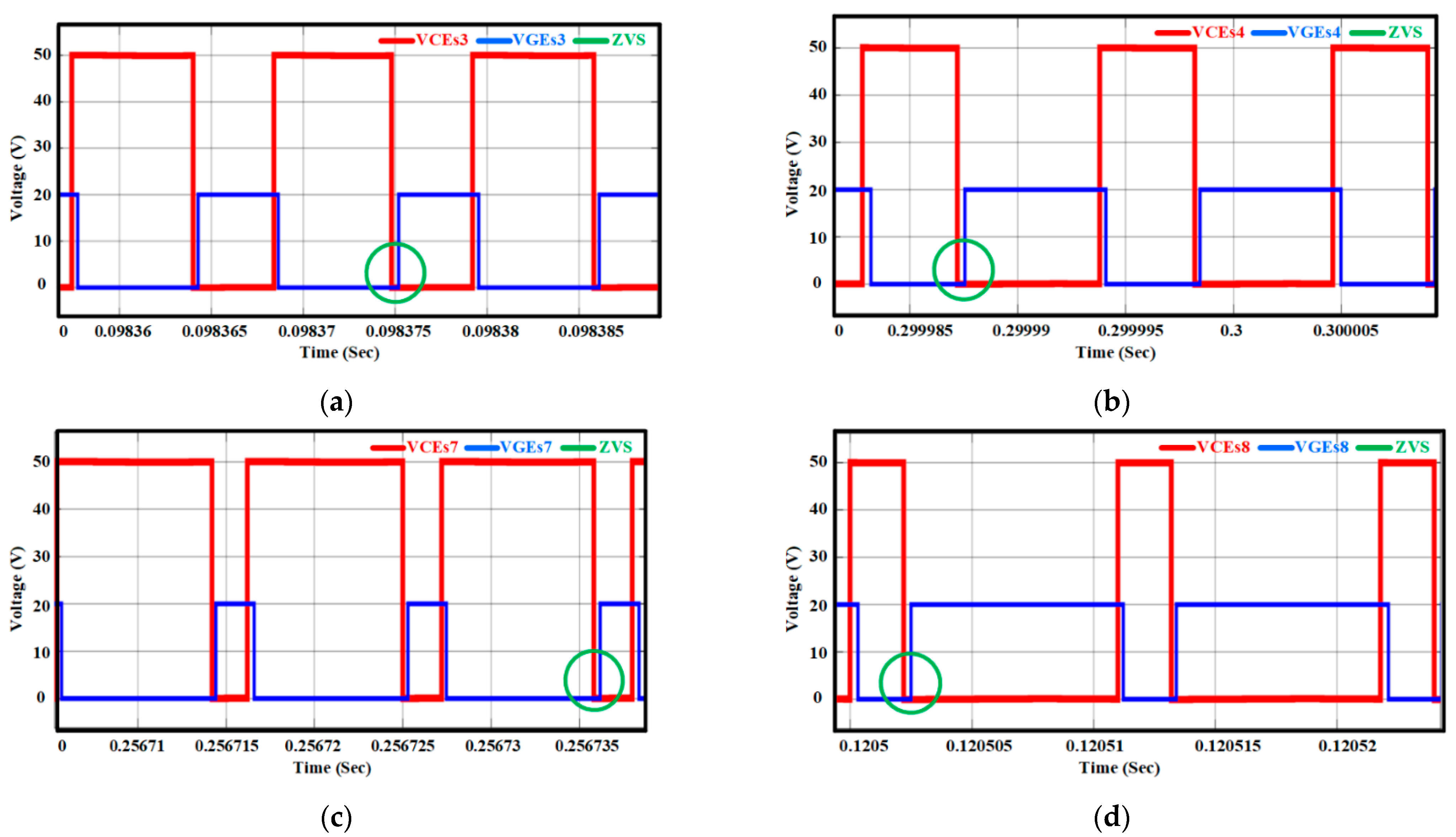
Figure 8 shows the simulation plots of the gate voltage VGE and collector voltage VCE. The gate voltage, VGE, and VCE were simulated for switches S3, S4, S7, and S8 of the inverter to verify the occurrence of ZVS, as shown in Figure 8. It was observed that the VCE had reached zero before all the switches started experiencing increase in the gate voltage, indicating that all the switches were switched ON at ZVS.
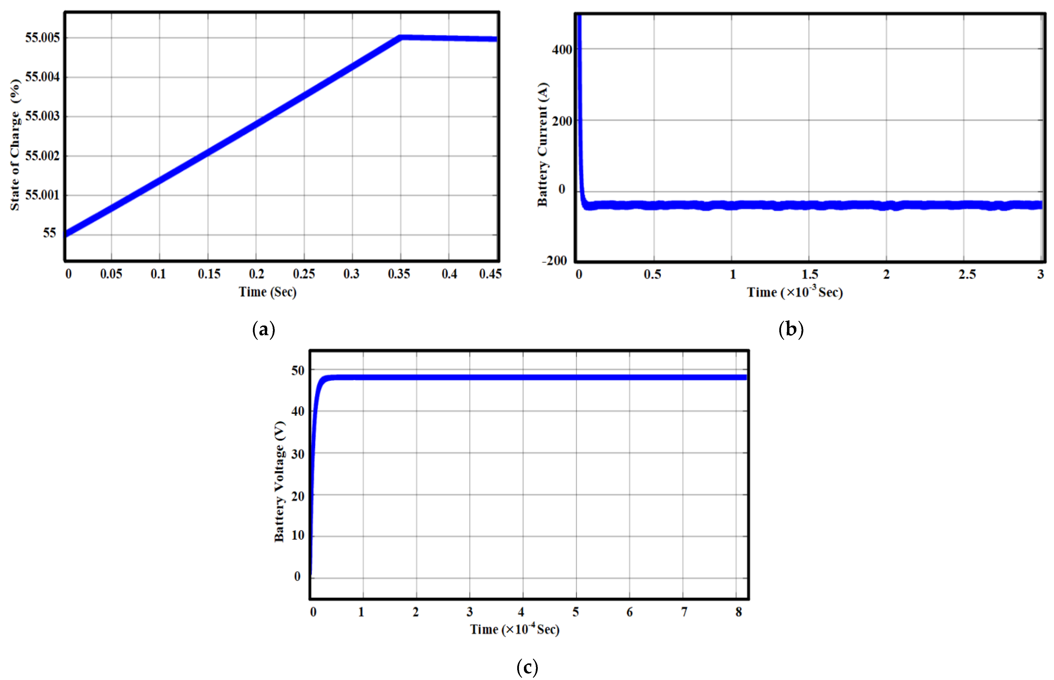
The output results of the battery side are presented in Figure 9. The battery output waveform included state of charge SOC%, current Ibat, and voltage Vbat waveforms. The state of charge was purposely increased, starting from the initial value, which was 55%, until it reached stable state. With the use of the constant voltage charging method, the voltage started to increase from zero. When it reached a constant value, the current began to drop and reached a negative value.
By employing a soft-switching technique, both low- and high-frequency current ripples were reduced on the battery, thus extending the battery life without compromising the charger’s size and reducing switching loss.

6. Experimental Results

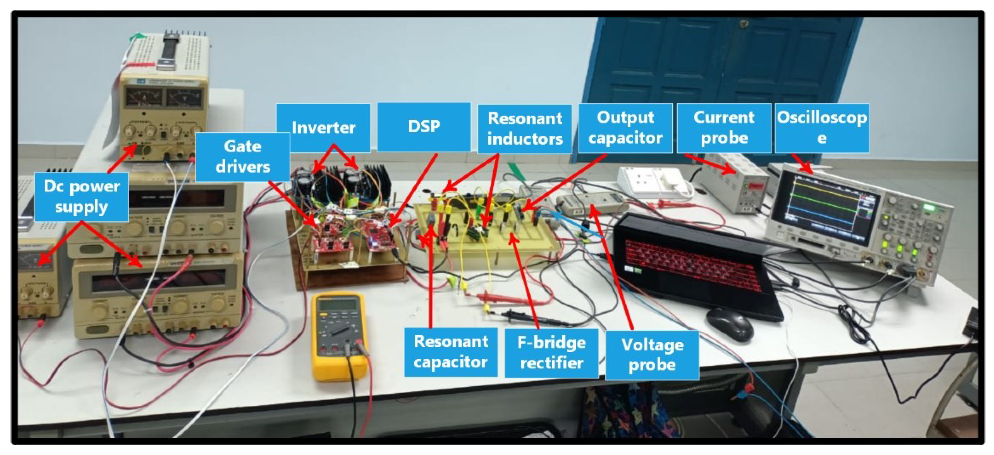
A prototype of the cascaded H-bridge multilevel inverter LLC resonant converter has been built to verify the theoretical and simulation outcomes, which is based on the specifications given in Table 1. Figure 10 shows the prototype, which has two bridges, the resonant branch, the output filter, the gate driver, and the DSP controller. The DSP control is realized using the TMS320F28379D chip, which is capable of high-speed processing of decimal data with a processing capability of 200 MHz. Table 2 shows the essential parameters coming from the proposed design approach, as well as the actual measured values. Table 3 lists the semiconductor device and major circuit components of the converter.
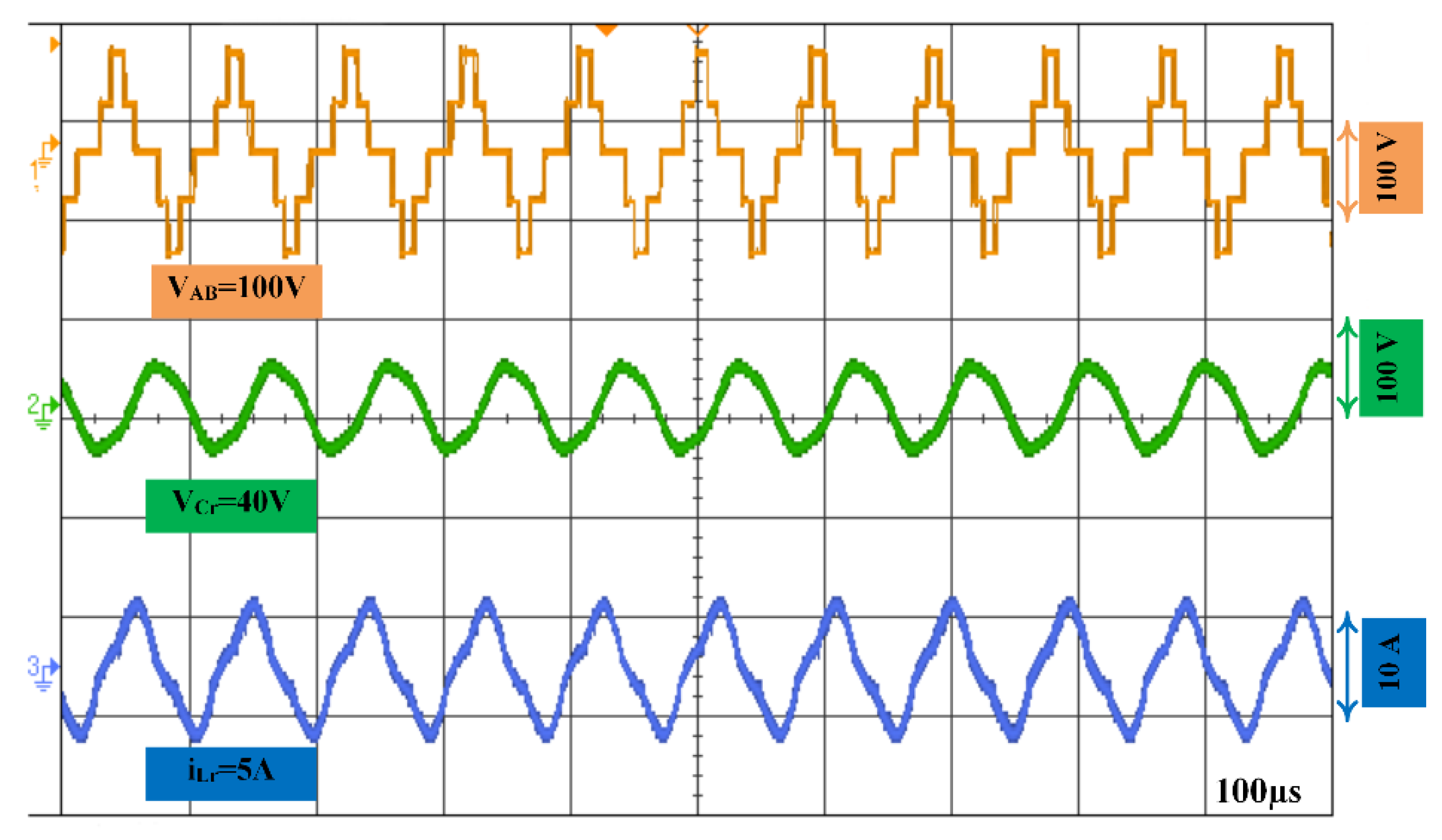
Figure 11 shows the experimental waveforms of the voltage across the resonant tank VAB, which is a five-level voltage. The voltage across the resonant capacitor (VCr), and the resonant inductor current iLr at Vin = 100. The resonant current and the voltage across the resonant capacitor are almost inverted in this diagram, as in Figure 11. It was evident that the resonant current began with a negative polarity in each half cycle, which allowed for the achievement of the ZVS for switching frequency at the resonant frequency (100 KHz). The obtained experimental output voltage resonant capacitor and current resonant were approximately 40 V and 5 A, respectively. Furthermore, it is worth noting that these findings are consistent with the simulation results depicted in Figure 7.
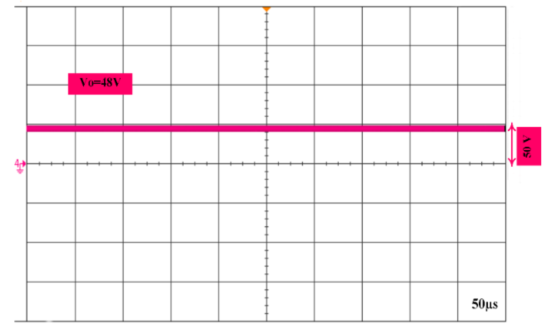
The experimental voltage waveforms from collector to emitter, VCEs1, VCEs2, VCEs5, and VCEs6, and gate signal voltages, VGS1, VGS2, VGS5, and VGS6, for the output load are shown in Figure 12. The collector and gate voltages for each switch show that the VCE was zero before switching ON the switches, which allowed the turning ON of the power switches in the ZVS mode. Hence, all the switches were turned ON at ZVS for the load selected as in Figure 12, which is consistent with the simulation results reported in Figure 8. Finally, Figure 13 shows the regulated output DC voltage; the value of the measured voltage was in agreement with the simulated value as in Figure 8, which is 48 V.
Table 4 shows the comparison between the conducted work and related LLC topologies for battery charger as reviewed in the literature. Based on the comparison results, the proposed converter requires less magnetic components, and less input voltage compared to previous converters reported in [6,29,30,31,34]. Furthermore, the design consideration and selected operation range proved that the proposed configuration has significantly enhanced efficiency compared to [29,30,34]. Even though the proposed converter has a higher number of active switches (8 switches), it has been proven to have better efficiency, less weight, and less cost due to proper design consideration, parameters, and operation range selection.

7. Conclusions

A five-level cascaded H-bridge LLC resonant converter for battery charger has been presented. The proposed converter is designed with proper operation region selection to obtain high power density, high efficiency, and less magnetic components to ensure the reduction on factors of size and cost. The range of operating frequency is set to be (91 kHz < fsw < 110 kHz), and LLC parameters are designed to achieve resonant frequency fr = 100 kHz to simplify the design considerations. The proposed converter performance had been compared to related works in literature, and evaluated by utilizing simulation (MATLAB/SIMULINK). An experimental prototype had been tested to achieve output power 100 W, 48 V, with efficiency around 96.9%. Thus, the evaluation of results and discussions proves that the theoretical, simulation, and experimental results are in agreement, and ensure the validity of this work.

8. Future Challenges

The major challenge in using the proposed converter is as a bidirectional DC–DC converter mode. This is because the diodes (full-bridge rectifier) used in proposed circuit are unidirectional and uncontrolled rectifiers. Second, if the diodes are replaced with active MOSFETs or IGBTs, then additional control strategies will be required in order to synchronously control the multilevel-inverter, resonant circuit, and the battery charger and discharger stages. By overcoming these limitations, a bidirectional behavior can be achieved by using the proposed structural, which will be the subject of future work and challenges in charger and discharger applications.

Author Contributions

Conceptualization, S.A., M.S. and I.A.; methodology, A.B. and D.I.; writing—original draft preparation, S.A., M.S. and A.B.; investigation, D.I., M.S. and M.K.; resources, M.K. and A.B.; writing—review and editing, M.S., I.A. and S.A.; visualization, M.K. and I.A.; supervision, M.S. and D.I.; funding acquisition, I.A. and M.S. All authors have read and agreed to the published version of the manuscript.

Funding

This work was supported by Universiti Kuala Lumpur under grant number UniKL/CoRI/UER20003.

Institutional Review Board Statement

Not applicable.

Informed Consent Statement

Not applicable.

Data Availability Statement

Not applicable.

Acknowledgments

The authors would like to acknowledge the financial support received from Universiti Kuala Lumpur under grant number UniKL/CoRI/UER20003. Also, the Universiti Sains Malaysia and the “Research Creativity and Management Office (RCMO)” are appreciated for supporting this work under short-term grant No. 304/PELECT/6315330.

Conflicts of Interest

The authors declare no conflict of interest.

References

  1. Wu, Y.-E.; Hsiao, S.-L. Novel High-Efficiency Three-Port Bidirectional Step-Up/Step-Down DC–DC Converter for Photovoltaic Systems. Sustainability 2021, 13, 7913. [Google Scholar] [CrossRef]
  2. Alatai, S.; Salem, M.; Ishak, D.; Das, H.S.; Alhuyi Nazari, M.; Bughneda, A.; Kamarol, M. A Review on State-of-the-Art Power Converters: Bidirectional, Resonant, Multilevel Converters and Their Derivatives. Appl. Sci. 2021, 11, 10172. [Google Scholar] [CrossRef]
  3. Viswanathan, B. Chapter 7-Solar Energy: Fundamentals. Energy Sources Fundam. Chem. Convers. Processes Appl. 2017, 139–147. [Google Scholar] [CrossRef]
  4. Karthikeyan, V.; Gupta, R. Distributed power flow control using cascaded multilevel isolated bidirectional DC–DC converter with multi-phase shift modulation. IET Power Electron. 2019, 12, 2996–3003. [Google Scholar] [CrossRef]
  5. Hussan, M.R.; Sarwar, A.; Siddique, M.D.; Mekhilef, S.; Ahmad, S.; Sharaf, M.; Zaindin, M.; Firdausi, M. A novel switched-capacitor multilevel inverter topology for energy storage and smart grid applications. Electronics 2020, 9, 1703. [Google Scholar] [CrossRef]
  6. Wang, S.; Liu, Y.; Wang, X. Resonant Converter for Battery Charging Applications With CC/CV Output Profiles. IEEE Access 2020, 8, 54879–54886. [Google Scholar] [CrossRef]
  7. Dhundhara, S.; Verma, Y.P.; Williams, A. Techno-economic analysis of the lithium-ion and lead-acid battery in microgrid systems. Energy Convers. Manag. 2018, 177, 122–142. [Google Scholar] [CrossRef]
  8. Al-Gabalawy, M.; Mahmoud, K.; Darwish, M.M.F.; Dawson, J.A.; Lehtonen, M.; Hosny, N.S. Reliable and Robust Observer for Simultaneously Estimating State-of-Charge and State-of-Health of LiFePO4 Batteries. Appl. Sci. 2021, 11, 3609. [Google Scholar] [CrossRef]
  9. Ali, E.S.; El-Sehiemy, R.A.; Abou El-Ela, A.A.; Mahmoud, K.; Lehtonen, M.; Darwish, M.M.F. An Effective Bi-Stage Method for Renewable Energy Sources Integration into Unbalanced Distribution Systems Considering Uncertainty. Processes 2021, 9, 471. [Google Scholar] [CrossRef]
  10. Bendary, A.F.; Abdelaziz, A.Y.; Ismail, M.M.; Mahmoud, K.; Lehtonen, M.; Darwish, M.M.F. Proposed ANFIS Based Approach for Fault Tracking, Detection, Clearing and Rearrangement for Photovoltaic System. Sensors 2021, 21, 2269. [Google Scholar] [CrossRef] [PubMed]
  11. Abbas, A.S.; El-Sehiemy, R.A.; Abou El-Ela, A.; Ali, E.S.; Mahmoud, K.; Lehtonen, M.; Darwish, M.M.F. Optimal Harmonic Mitigation in Distribution Systems with Inverter Based Distributed Generation. Appl. Sci. 2021, 11, 774. [Google Scholar] [CrossRef]
  12. Ryu, S.; Woo, D.; Kim, M.; Lee, B. Analysis and Design of Modified Half-Bridge Series-Resonant Inverter With DC-Link Neutral-Point-Clamped Cell. IEEE Trans. Power Electron. 2016, 31, 2282–2295. [Google Scholar] [CrossRef]
  13. Dominguez, A.; Barragan, L.A.; Artigas, J.I.; Otin, A.; Urriza, I.; Navarro, D. Reduced-Order Models of Series Resonant Inverters in Induction Heating Applications. IEEE Trans. Power Electron. 2017, 32, 2300–2311. [Google Scholar] [CrossRef] [Green Version]
  14. Jiang, C.; Chau, K.; Liu, C.; Lee, C.H. An overview of resonant circuits for wireless power transfer. Energies 2017, 10, 894. [Google Scholar] [CrossRef]
  15. Haga, H.; Kurokawa, F. Modulation method of a full-bridge three-level LLC resonant converter for battery charger of electrical vehicles. IEEE Trans. Power Electron. 2016, 32, 2498–2507. [Google Scholar] [CrossRef]
  16. Tang, X.; Li, Z.; Zhang, M. A Wide-Range Frequency Model for Dielectric Barrier Discharge Type Ozone Generators Powered by Series Resonant Inverters. IEEE Access 2019, 7, 124309–124314. [Google Scholar] [CrossRef]
  17. Salem, M.; Ramachandaramurthy, V.K.; Jusoh, A.; Padmanaban, S.; Kamarol, M.; Teh, J.; Ishak, D. Three-Phase Series Resonant DC-DC Boost Converter With Double LLC Resonant Tanks and Variable Frequency Control. IEEE Access 2020, 8, 22386–22399. [Google Scholar] [CrossRef]
  18. Maamar, A.E.T.; Helaimi, M.H.; Taleb, R.; Kermadi, M.; Mekhilef, S.; Wahyudie, A.; Rawa, M. Analysis and Small Signal Modeling of Five-Level Series Resonant Inverter. IEEE Access 2021, 9, 109384–109395. [Google Scholar] [CrossRef]
  19. Siddique, M.D.; Mekhilef, S.; Shah, N.M.; Memon, M.A. Optimal design of a new cascaded multilevel inverter topology with reduced switch count. IEEE Access 2019, 7, 24498–24510. [Google Scholar] [CrossRef]
  20. Vemuganti, H.P.; Sreenivasarao, D.; Ganjikunta, S.K.; Suryawanshi, H.M.; Abu-Rub, H. A Survey on Reduced Switch Count Multilevel Inverters. IEEE Open J. Ind. Electron. Soc. 2021, 2, 80–111. [Google Scholar] [CrossRef]
  21. Rashid, M.H. Power Electronics Handbook; Butterworth-Heinemann: Oxford, UK, 2017. [Google Scholar]
  22. Gadalla, A.S.; Yan, X.; Hasabelrasul, H. Performance of the battery energy storage systems based on cascaded H-bridge multilevel converter. J. Eng. 2019, 2019, 779–783. [Google Scholar] [CrossRef]
  23. Song, J.; Zhang, W.; Liang, H.; Jiang, J.; Yu, W. Fault-Tolerant Control for a Flexible Group Battery Energy Storage System Based on Cascaded Multilevel Converters. Energies 2018, 11, 171. [Google Scholar] [CrossRef] [Green Version]
  24. Agostini, E.; Barbi, I. Three-Phase Three-Level PWM DC–DC Converter. IEEE Trans. Power Electron. 2011, 26, 1847–1856. [Google Scholar] [CrossRef]
  25. Siddique, M.D.; Mekhilef, S.; Shah, N.M.; Sarwar, A.; Memon, M.A. A new single-phase cascaded multilevel inverter topology with reduced number of switches and voltage stress. Int. Trans. Electr. Energy Syst. 2020, 30, e12191. [Google Scholar] [CrossRef]
  26. Dao, N.D.; Lee, D. Operation and Control Scheme of a Five-Level Hybrid Inverter for Medium-Voltage Motor Drives. IEEE Trans. Power Electron. 2018, 33, 10178–10187. [Google Scholar] [CrossRef]
  27. Ding, K.; Cheng, K.W.E.; Wang, S.X.; Wang, D.H.; Shi, Z. Five-level cascaded multilevel motor driver for electrical vehicle with battery charge management. In Proceedings of the 2008 Australasian Universities Power Engineering Conference, Sydney, Australia, 14–17 December 2008; pp. 1–6. [Google Scholar]
  28. Tolbert, L.A.; Fang Zheng, P.; Cunnyngham, T.; Chiasson, J.N. Charge balance control schemes for cascade multilevel converter in hybrid electric vehicles. IEEE Trans. Ind. Electron. 2002, 49, 1058–1064. [Google Scholar] [CrossRef] [Green Version]
  29. Kim, D.-H.; Kim, M.-S.; Hussain Nengroo, S.; Kim, C.-H.; Kim, H.-J. LLC Resonant Converter for LEV (Light Electric Vehicle) Fast Chargers. Electronics 2019, 8, 362. [Google Scholar] [CrossRef] [Green Version]
  30. Wei, Y.; Luo, Q.; Du, X.; Altin, N.; Nasiri, A.; Alonso, J.M. A Dual Half-Bridge LLC Resonant Converter With Magnetic Control for Battery Charger Application. IEEE Trans. Power Electron. 2020, 35, 2196–2207. [Google Scholar] [CrossRef]
  31. Deng, J.; Li, S.; Hu, S.; Mi, C.C.; Ma, R. Design Methodology of LLC Resonant Converters for Electric Vehicle Battery Chargers. IEEE Trans. Veh. Technol. 2014, 63, 1581–1592. [Google Scholar] [CrossRef]
  32. Yilei, G.; Zhengyu, L.; Lijun, H.; Zhaoming, Q.; Guisong, H. Three-level LLC series resonant DC/DC converter. IEEE Trans. Power Electron. 2005, 20, 781–789. [Google Scholar] [CrossRef]
  33. Lee, I.; Moon, G. Analysis and Design of a Three-Level LLC Series Resonant Converter for High- and Wide-Input-Voltage Applications. IEEE Trans. Power Electron. 2012, 27, 2966–2979. [Google Scholar] [CrossRef]
  34. Zong, S.; Luo, Q.; Li, C.; Li, W.; He, X.; Su, S. Three-level frequency-doubling LLC resonant converter with high step-down ratio for high input voltage applications. In Proceedings of the 2014 IEEE Applied Power Electronics Conference and Exposition—APEC, Fort Worth, TX, USA, 16–20 March 2014; pp. 14–19. [Google Scholar]
  35. Jin, F.; Liu, F.; Ruan, X.; Meng, X. Multi-phase multi-level LLC resonant converter with low voltage stress on the primary-side switches. In Proceedings of the 2014 IEEE Energy Conversion Congress and Exposition (ECCE), Pittsburgh, PA, USA, 14–18 September 2014; pp. 4704–4710. [Google Scholar]
  36. Peter, A.K.; Mathew, J. A Single Phase, Single Stage AC-DC Multilevel LLC Resonant Converter With Power Factor Correction. IEEE Access 2021, 9, 70884–70895. [Google Scholar] [CrossRef]
  37. Kirshenboim, O.; Peretz, M.M. Combined Multilevel and Two-Phase Interleaved LLC Converter With Enhanced Power Processing Characteristics and Natural Current Sharing. IEEE Trans. Power Electron. 2018, 33, 5613–5620. [Google Scholar] [CrossRef]
  38. Chen, G.; Li, H.; Sun, X.; Wang, Y. A Method for Designing Resonant Tank of Half-Bridge Three-Level LLC Converter. In Proceedings of the 2018 Chinese Automation Congress (CAC), Xi’an, China, 30 November–2 December 2018; pp. 2312–2316. [Google Scholar]
  39. Alatai, S.; Salem, M.; Ishak, D.; Kamarol, M.; Jamil, M.; Bughneda, A. Design and Analysis of Five-level cascaded LLC Resonant Converter. In Proceedings of the 2020 IEEE International Conference on Power and Energy (PECon), Penang, Malaysia, 7–8 December 2020; pp. 66–70. [Google Scholar]
  40. Deng, J.; Mi, C.C.; Ma, R.; Li, S. Design of LLC Resonant Converters Based on Operation-Mode Analysis for Level Two PHEV Battery Chargers. IEEE/ASME Trans. Mechatron. 2015, 20, 1595–1606. [Google Scholar] [CrossRef]
  41. Bughneda, A.; Salem, M.; Nazari, M.A.; Ishak, D.; Kamarol, M.; Alatai, S. Resonant Power Converters for Renewable Energy Applications: A Comprehensive Review. Front. Energy Res. 2022, 10, 846067. [Google Scholar] [CrossRef]
  42. Abdel-Rahman, S. Resonant LLC converter: Operation and design. Infineon Technol. N. Am. Corp 2012, 19, 1–19. [Google Scholar]
  43. Salem, M.; Jusoh, A.; Dahidah, M.; Ishak, D.; Richelli, A.; Alhamroni, I.; Kamarol, M. Improved topology of three-phase series resonant DC-DC boost converter with variable frequency control. Alex. Eng. J. 2022, 61, 1701–1713. [Google Scholar] [CrossRef]
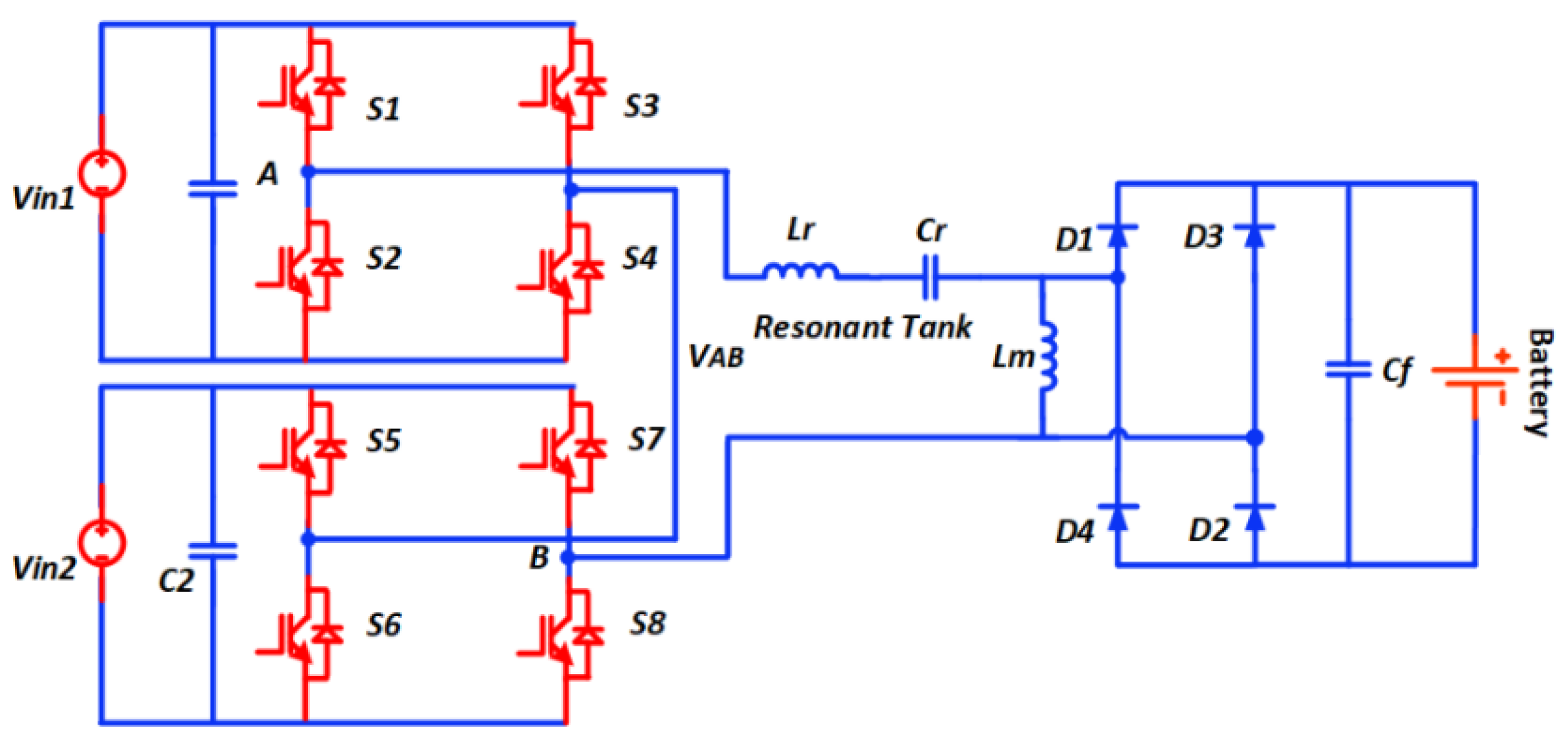
Figure 1. The five-level LLC resonant DC–DC converter structure.
Sustainability 14 08255 g001
Figure 2. Input voltage to the LLC stage VAB.
Sustainability 14 08255 g002
Figure 3. Controlled gate signals and output voltage VAB of five level inverter and simulated waveforms of system VAB, Vcr, iLr, ID1-4.
Sustainability 14 08255 g003
Figure 4. Operation stages for the proposed five-level converter during: (a) VAB = +2Vdc; (b) VAB= +Vdc; (c) VAB = 0; (d) VAB = −Vdc; (e) VAB= −2Vdc.
Sustainability 14 08255 g004aSustainability 14 08255 g004b
Figure 5. AC equivalent circuit of the LLC resonant converter.
Sustainability 14 08255 g005
Figure 6. Voltage gain versus normalized frequency of the proposed converter. (a) Different load factors with constant Ln = 3. (b) Different inductance ratios with constant Q = 0.39.
Sustainability 14 08255 g006
Figure 7. Simulation waveforms of proposed converter of five-level inverter voltage VAB, resonant capacitor voltage VCr, and resonant inductor current iLr.
Sustainability 14 08255 g007
Figure 8. Simulation waveforms of gate voltage VGE and collector voltage VCE of switches (a) switch 3, (b) switch 4, (c) switch 7, and (d) switch 8.
Sustainability 14 08255 g008
Figure 9. Simulated response of battery load (a) state of charge, (b) current, and (c) voltage.
Sustainability 14 08255 g009
Figure 10. Experiment setup of proposed converter.
Sustainability 14 08255 g010
Figure 11. Experimental waveforms of voltage across multilevel inverter VAB, resonant capacitor, VCr and resonant current, iLr, for the output load resistance of 23 Ω.
Sustainability 14 08255 g011
Figure 12. Measured waveforms of gate voltage VGE and collector voltage VCE for switches (a) S1 and S2, (b) S5 and S6.
Sustainability 14 08255 g012
Figure 13. Experimental waveform of output voltage.
Sustainability 14 08255 g013
Table 1. Converter Specification.
ParameterSymbolValue
Input voltage rangeVin,min~Vin,max60–140 V
Input voltage NominalVin,nom100 V
Output voltageVb48 V
Output powerPbat100 W
Resonant frequencyFr1100 kHz
Switching frequencyFsw91–110 kHz
Table 2. Design parameters of experimental prototype.
ParameterSymbolCalculated ValueMeasured Value
Input voltage NominalVin,nom100 V100 V
Resonant capacitancescr218.5 nF215 nF
Resonant inductancesLr11.5 µH12 µH
Magnetizing inductanceLm34.7 µH35 µH
Equivalent load resistanceRac18.67 Ω18.67 Ω
Output voltageVo48 V48 V
Table 3. Components used in the experimental prototype of converter.
ComponentPart Number
Active Switches (S1–S8)GP35B60PD
MicrocontrollerLAUNCHXL-F28379D LaunchPad
Magnetic ferrite coreETD 34/17/11
Resonant capacitorKEMET R75 Film Capacitor
Diodes D1–D4MUR1560G
Table 4. Comparison between proposed topology and existing topologies.
TopologyNo of SwitchesNo of Rectifier No of TransformerInput Voltage VOutput Voltage VPower Rated wSwathing Frequency Range kHzModulationEfficiency
Half-bridge LLC [6]281200100200100PWM 197%
Full bridge LLC [29]441250–310 VAC25.6–33.6100030–100PFM 296.4%
Dual Half-bridge LLC [30]282340–380120–160320100MC 395.5%
Full bridge LLC [31]441400250–4503300154.7–220-98.2%
Three level LLC [34]4216004880050PFM95.1%
Proposed8401004810091–110(PWM) (PFM)96.9%
1 Pulse width modulation. 2 Pulse Frequency modulation. 3 Magnetic control.
Publisher’s Note: MDPI stays neutral with regard to jurisdictional claims in published maps and institutional affiliations.