Article

Sustainable Design of Temporary Buildings in Emergency Situations

Department of Civil, Environmental and Architectural Engineering, University of Padova, Via Marzolo 9, 35131 Padova, Italy
*
Author to whom correspondence should be addressed.
Sustainability 2022, 14(13), 8010; https://doi.org/10.3390/su14138010
Submission received: 29 April 2022 / Revised: 25 May 2022 / Accepted: 26 May 2022 / Published: 30 June 2022

Abstract

:
Unforeseen circumstances that occur anywhere in the world following natural disasters, humanitarian and health emergencies, armed conflicts, or in the presence of migratory flows, require adequate and immediate responses. This work aims to analyze the project requirements useful to realizing modular systems for residential, multifunctional, and hospital intended use, which, even if temporary, can ensure a high-performance standard in terms of comfort and energy efficiency, and at the same time guarantee the possibility of use in the widest possible range and in rapid execution times. The considered requirements have been those of settlement in the territory, energy efficiency, transportability, and re-usability. Temporary modular systems put in place with the abovementioned requirements are the basis of the design proposal; to realize this, they are made with dry technology to be reusable and energy-efficient. Furthermore, this enables the reduction of the minimum modules’ production and times of execution in applying both requirements of standardization and modular coordination. All these requirements also add to the ones relating to energy efficiency, transportability, and reusability, which are the pillars of the project for the achievement of performance above all in terms of standards and comfort levels as it is possible to find in the sustainable building of the living period.

1. Introduction

The occurrence of natural disasters, humanitarian and health emergencies, armed conflicts, or migratory flows can have an impact on the population and require assistance and additional resources for management and relief. In addition, these can cause a large number of human losses and represent a break in the relationship between people and their environment [1,2]. The resulting state of emergency [3] can be defined as a sudden phenomenon whereby urban spaces, in a short time, are transformed to accommodate temporary settlements [4], which are a response to the needs of the population affected.
The term disaster, as defined from a terminological point of view (UNISDR, 2009) [5], and later taken up by the Commission on International Law at the Third United Nations World Conference on Disaster Risk Reduction held in Sendai, Japan, March 2015 [6], focuses mainly on the consequences that these events have on the functioning of society. These events are so shocking that they no longer allow society itself to resume normal functioning without external aid. In line with the above definitions, the CRED (Centre for Research on the Epidemiology of Disasters) also defines a disaster [7] as a situation or event overwhelming local capacity and involving external assistance, a request both at the national and international level.
In the period from 1998 to 2009, different types of disasters, including the meteorological, geophysical, and technological ones, have been mapped by the EEA (European Environment Agency) [8]. At the same time, the agency provided data for 32 countries under consideration, of which 27 correspond to the EU Member States. Others are Iceland, Liechtenstein, Norway, Switzerland, and Turkey. According to the survey, the number and impact of disasters in Europe caused more than 100,000 deaths and economic losses estimated at EUR 150 billion with a strong increase. The impact of natural hazards, in terms of fatal accidents, throughout Europe is not uniform. As also shown in the report drawn up by UNISDR (United Nations Office for Disaster Risk Reduction) [9], Italy is one of the countries most sensitive to catastrophic events and ranks among the top 10 countries in the world for value generated and expected average losses caused by catastrophic natural events, occupying the fourth place behind Japan, the United States, and China.
The Italian territory already exposed to seismic, volcanic, and hydrogeological risks [10] now also faces the risks of climate change [11]; the latter has increased the risks for the inhabitants exponentially [12].
Moreover, Italy dealt with various emergencies caused by natural disasters (earthquakes, landslides, floods, exceptional snowfalls, etc.), some of which occurred at the same time, as reported, for example, in the chronicle of the day of 18 January 2017 [13], in which abundant snowfalls occurred after the earthquake. Many devasting events that have interested Italy in the past five decades have given rise to the need for immediate responses to an unexpected demand for housing [14] that are appropriate to the different climatic situations [15], depending on the context.
Finally, the study (Coronese et al.) [16] was carried out concerning the analysis of data relating to a large number of disasters, it is shown that the damage caused by extreme events has increased considerably in the last 50 years; in fact, taking as reference the period between 1970 and 2010, the analysis of the data has demonstrated that the economic impact of a particularly nefarious disaster has increased approximately 20 times.
Over time, an important debate about the most appropriate approaches and models for emergency management has been developed; for example, the post-emergency reconstruction process theorized by Kates and Haas [17] addresses the issue of how to rebuild after a disaster, with an approach that starts from the assumption that the reconstruction must be a process “ordered, knowable and predictable” first and foremost.
The authors, therefore, envisage not so much a method, but rather a real model derived from the analysis of dozens of cases in various parts of the world. In contrast to this model, Hogg [18] and Neal [19] argue that a linear and orderly representation cannot be sought in the face of uncertain process dynamics; they observe that the four phases identified by Kates and Hass can, in many cases, not be distinguished, taking place almost simultaneously and interweaving each other.
The debate, to date, is still open and focused on how the context and scenario can influence the reconstruction process regarding objectives, strategies, and governance [20,21].
The management models and the temporary buildings that can be used in the emergency, the latter object of the present work, are traceable to diversified solutions for the various phases. The reconstructive process [22,23] develops, in fact, in different phases, such as acute, post-acute, rehabilitation, and reconstruction. The acute emergency phase develops itself between 12 and 48 h after the event. The settlements, in this phase corresponding to the very early hours, are made with tents. At first, the civil protection areas are set up as waiting, aggregation of the rescuers, and shelter areas for the reception of the people in the tents, with more rapidly mounting solutions therefore prepared to provide a shelter ready from the first night. The next post-acute phase goes from 2 to 30 days and also in this phase the tents are used. The next phase of rehabilitation goes from 1 to 3 months until 12 months and beyond in many cases; in this phase, there is the dismantling of the tents, and the settlements for hospitalizing the population are made of temporary buildings that are emergency housing units, such as containers or prefabricated buildings. The timing of the different phases is indicative because it is dictated by the contingent situations that occur for the specific disaster [24,25].
In the context of temporary buildings [26], emergency housing units are considered to be suitable solutions to meet the housing needs of the population for an estimated period of approximately two years; the latter is taken as a reference period necessary for damaged and/or no longer usable buildings to be rebuilt and/or repaired and to be occupied again.

2. Project Requirements

The focus of this paper is to identify the project requirements [27] for the implementation of modular systems for residential, multifunctional, and hospital intended use, that, although temporary, can ensure a high standard of performance in terms of comfort and energy efficiency and, at the same time, ensure the possibility of use in the widest possible range and in rapid execution times, as well as to re-employ at another site once they have ended their function at the end of an emergency period [28,29]. The requirements adopted and the basis of the project proposal were those of settleability in the territory, energy efficiency, transportability, and reuse.
Modular systems must be designed and built to meet the different needs of users and must be usable in different emergency contexts [30]; this means providing for their use in different possible locations and different climatic contexts.
Furthermore, the special nature of emergency construction [31] requires the construction to run very fast, and consequently, for that type of building, strong importance assumes the ability to transport components.
Taking into account these additional considerations, the project proposal concerns a modular system made in a different environment from that of use, whose components are therefore produced in the factory, easily transportable, quickly assembled, and adaptable to the morphological, environmental, and climatic characteristics of the territory of settlement, as well as achievable at a spatial level and for the number of units, in a functional way compared to the size of the emergency and, finally, reusable [32]. The project module must also be adaptable to use as a single and self-sufficient building or, usable as a structure in support of another existing in the context.

2.1. Settleability in the Territory

This criterion has to be taken into account still in the planning phase of the emergency response [33]. It is observed that the emergency response in terms of temporary buildings adapted to the context is the more effective the more it is previously planned to identify and prepare the necessary spaces for the operations of assistance to the population and the restoration of the primary functions of the community [34]. The success and the feasibility of the intervention, therefore, depend on the ability of local governments to operate in the field of planning the development of the territory and the protection of public safety.
To ensure proper emergency planning, it is necessary first of all to identify the areas necessary for the management of a crisis linked to the violent alteration of spatial planning. Emergency planning, therefore, cannot be understood only as a simple “census of resources” or as a “codification of the procedures for activation of the civil protection system in case of emergency” but as a real fundamental tool to organize the territory concerning the possible risks to which it is exposed.
The “spaces” to be identified in the emergency plan may be defined as:
-
clustering areas, for the dispatch of civil protection forces and resources in the case of an event;
-
waiting for areas or “meeting points”, as a point of collection of the population at the occurrence of a calamitous event;
-
reception areas, for the installation of suitable materials and facilities to ensure housing assistance to the population.
-
The attention goes to these latter ones that must have some specific characteristics:
-
suitable, in terms of size, for accommodating the number of persons expected to be affected by the emergency;
-
located on a site easily accessible even by large vehicles;
-
the availability of easily connectable water and electricity resources in the vicinity;
-
are safe areas about possible risks of flooding, hydrogeological disruption, or disruption of services and/or use of primary infrastructure.
The requirement of settlement is not specific to the system but becomes essential so that any design proposal can have the opportunity to be successfully implemented.

2.2. Energy Efficiency for Temporary Buildings

Facing numerous seismic events [35] that have included Italy, the use of temporary buildings [36], both for residential units and school modules, exceeded two years. This is shown in the analysis of the responses given to emergencies [37], as in the case of the earthquake in L’Aquila in 2009 [38]; these, to date, are still in use by the MUSP (Figure 1) Modules for Temporary School Building, including several cases over more than ten years of use.
In particular, the Directive 2010/31 in Article 4, concerning the energy performance requirement applied to temporary buildings, lays down minimum energy performance requirements for buildings or building units to achieve cost-optimal levels. According to this, the minimum requirements for the temporary building could not be applied by the Member States, as the period of use is deemed not to exceed two years.
Temporary buildings used in emergencies are therefore not required to meet the minimum energy performance requirements; however, being used for many more years than originally planned, not only do they not guarantee the comfort of the occupants, but also they are, economically, very expensive from a managerial point of view because of their high energy consumption, protracted over time.
Considering the MAP (temporary housing modules) (Figure 2), illustrative is the fact that occurred in the aftermath of the earthquake that struck Emilia Romagna in 2012, in which, due to the high cost of energy consumption for domestic use borne by families, the Emilia Romagna Region had to intervene to sign a specific agreement on tariffs with Enel (National Authority for Electricity) [39].
The continuous occurrence of calamitous events and the consequent use of temporary emergency buildings [40,41] has therefore also led the theme of temporary and quality housing to a constant confrontation to the planning of emergency interventions and the possible lines of development that can be adopted in emergency planning.
To meet the energy efficiency requirements [42] for the design of the building envelope, technological solutions may be proposed based on the use of technical elements made with wall and floor stratigraphies using concrete structural panels, pre-accoupled with rock wool insulation panels [43,44], or based on the use of container modules [45,46], suitably insulated by the application of a layer of insulating paint. A building envelope, regardless of the construction technique used to make it, must ensure internal environmental comfort and, with few changes, must be able to be used in different climatic situations.
Finally, to achieve high energy performance of the system in relation to the needs estimated for the specific case, it is possible to use systems based on the production of energy from renewable sources, for example, with the use of photovoltaic systems and integrated solar thermal panels.

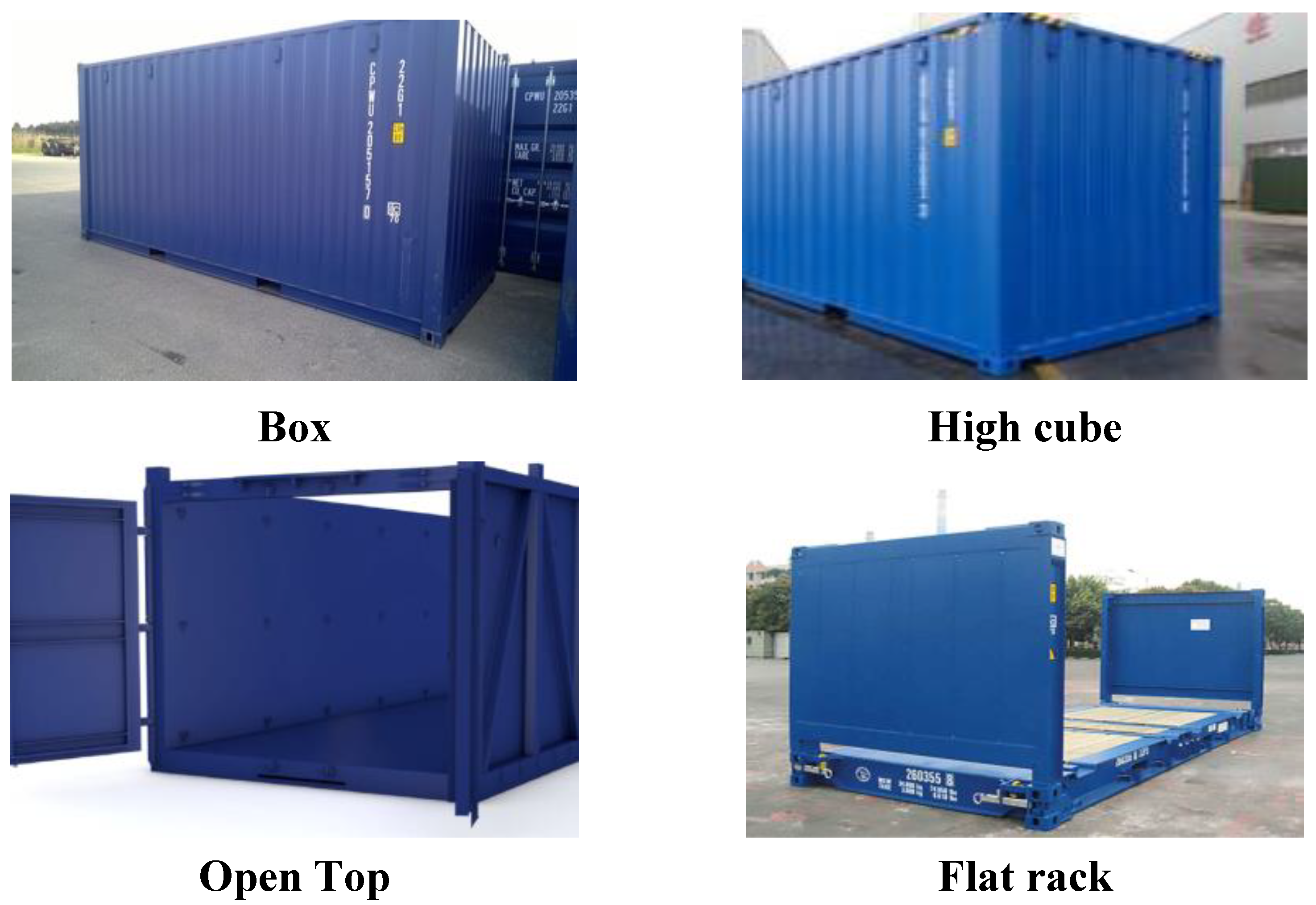
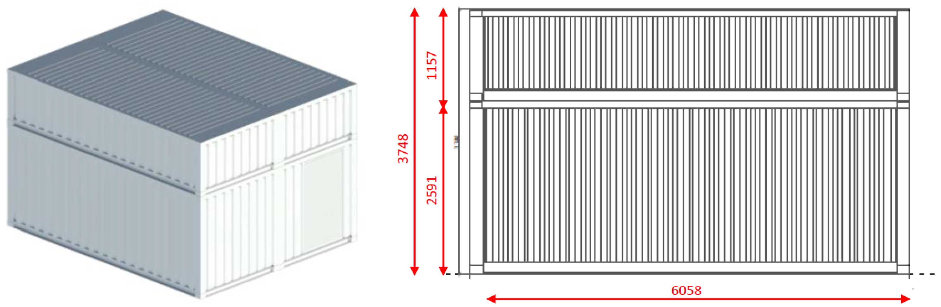
2.3. Transportability

As one of the requirements is the portability of the system [47], in designing the system from the dimensional point of view, reference was made to the dimensions of the containers that could be used for transport. As is known, containers are multipurpose, suitable for use in various types of freight transport, thanks to their robustness, practicality, and standardization (ISO 668:2020). The many advantages of using containers have led to a rapid spread of this system, which was developed between the 1960s and 1970s, starting from an idea of the American entrepreneur Malcolm Purcell McLean [48], considered by many the “father” of containerization, which is now a universally recognized and used standard [49].
With the use of the container, goods can be moved without having to handle them individually; the advantages are mainly the reduction in the damages of the cargo and more efficient logistic operations, with the result of a greater speed of boarding and disembarkation, which translates into an increase in the worked volumes, and a drastic reduction in handling costs.
The container according to the reference standard is permanent and therefore sufficiently resistant to be used repeatedly; it is especially designed to facilitate the transport of goods by one or more modes of transport, without intermediate load. It shall be equipped with devices for prompt handling, in particular, the transfer from one mode of transport to another; it shall be designed to be easy to fill and empty; it shall have an internal volume equal to or greater than 1 m3 (35,3ft3). In the case of emergencies, the advantage of the use of the container is evidenced in the fact that the marine/fluvial shipments are integrated with those of transport on road and railway and therefore, the effective realization of the multimodality can guarantee the transport of the modules with greater speed from the place of deposit to the site of use.
From the dimensional point of view, the container is a metal parallelepiped with measures established in the international ISO in 1967. Faced with a common width of 8 feet (about 244 cm) the container has heights of 8 feet (about 244 cm), 8 feet and 6 inches (about 259 cm), and 9 feet and 6 inches (about 290 cm) and are made between other measures in two standard lengths of 20 and 40 feet (approximately 605 cm and 1220 cm, respectively).

Types of Containers Available on the Market

Currently, on the market, there are, among others, four categories of containers of standard dimensions, usable for transport and handling such as the container box, the high cube container, the open-top container, and the flat rack container. Each container consists of a load-bearing part and a carried part where the latter is not binding; therefore, different configurations exist for the same container geometry of the four categories mentioned above (Figure 3).
There are two types of container boxes on the market, 20′ and 40′, with the length of one double the other. The high cube container has the same dimensions as the 40′ container box but with a higher height; both the container box and the high cube container have an opening on one of the two short sides. The open-top container, as well as the container box, comes in two versions, 20′ and 40′, one double the other, and has both an opening on one of the two short sides, and on the roof. The flat rack container, also in two sizes, 20′ and 40′, has an opening on the long side of the container itself and the roof is not present. Table 1 shows the dimensions of the different types of containers and Table 2 shows the main dimensions reference for open-top containers, including both 20′ and 40′.
The dimensional analysis conducted on the types of containers on the market was taken as a reference of the measures of the container model open-top 20′, and then the design module of the proposed system was made to be compatible with it.

2.4. The Reusability

Concerning the reusability requirement, the choice of elements being made dry [50] or modular, considered for each class of technical elements of the technological system, significantly influenced the design proposal.
In particular, it should be noted that the foundations of columns with screws are optimal [51]; made of hot-dip galvanized steel; available in different sizes both in height and in diameter, where appropriate; and include propellers, depending on the bearing capacity of the ground and the operating loads.
These types of foundations, particularly versatile for temporary use, are, in different cases, a valid alternative to concrete ones, and are easy to install, remove, and reuse. Indeed, they can be installed using pole-screwed fixtures and easily carried out in different ways, as shown in Figure 4.
There exists the possibility of loading the foundations immediately after their construction with the non-use of benthic sludge, and the limited vibrations constitute indisputable advantages of this type of foundation.

2.5. Other Requirements

In addition to the above, the requirements of cost-effectiveness [52] and speed of construction must also be taken into account [53]. The latter is undoubtedly achieved by the choice of dry technology. The times, in this case, are dictated only by the assembly of the component elements and there are, for example, waits for the maturation of any castings or waiting times for drying, as in the case of wet processing.

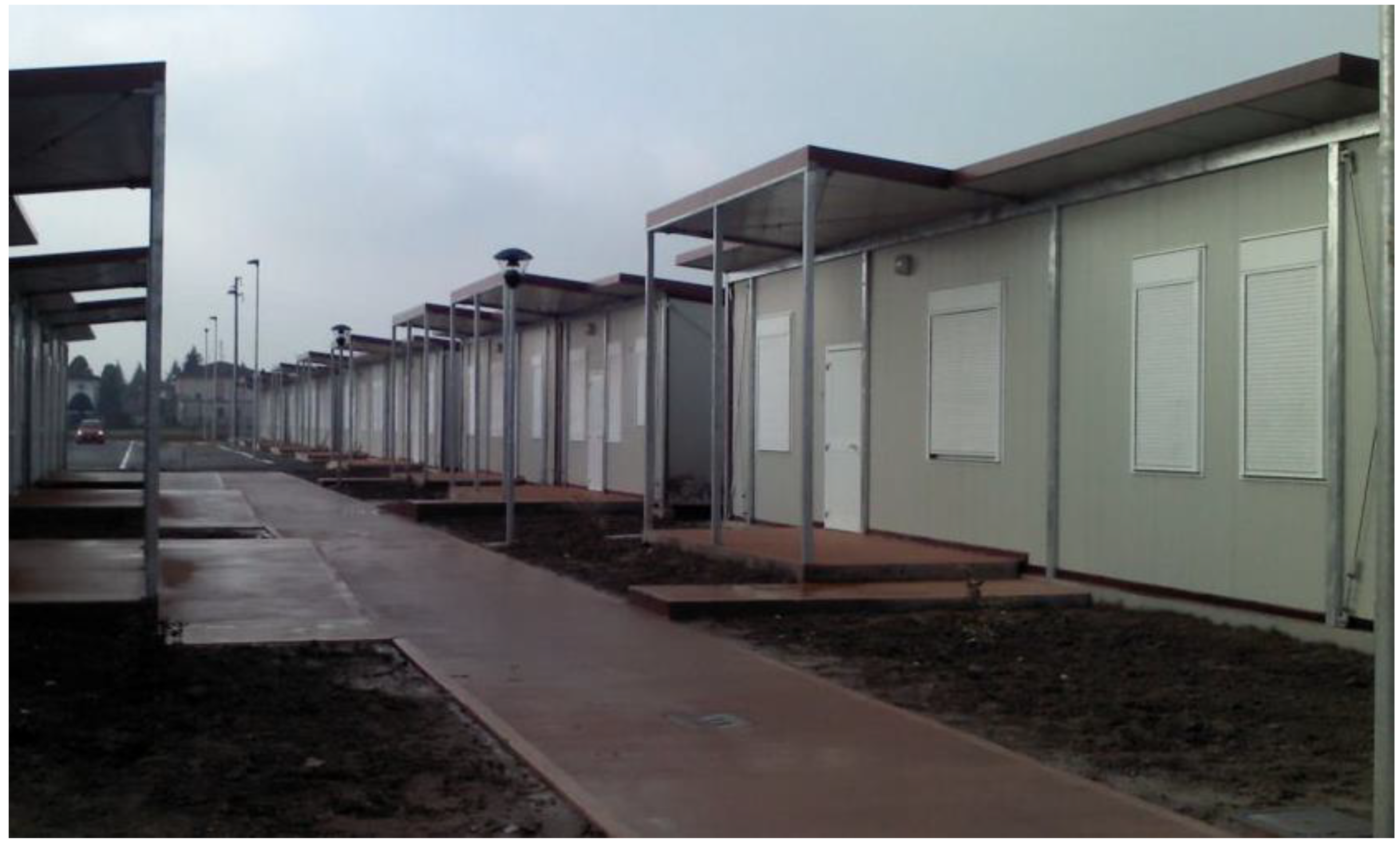
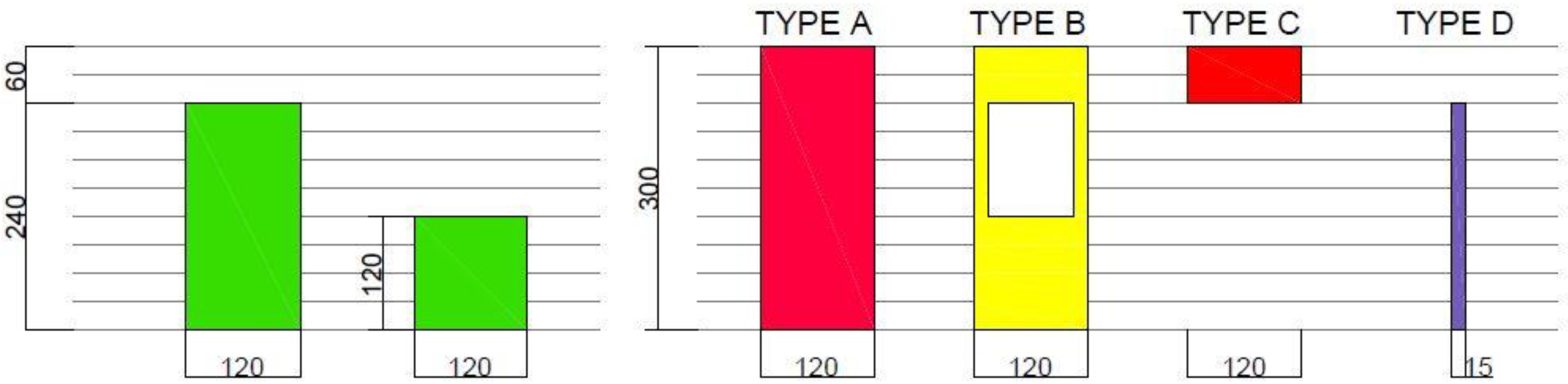
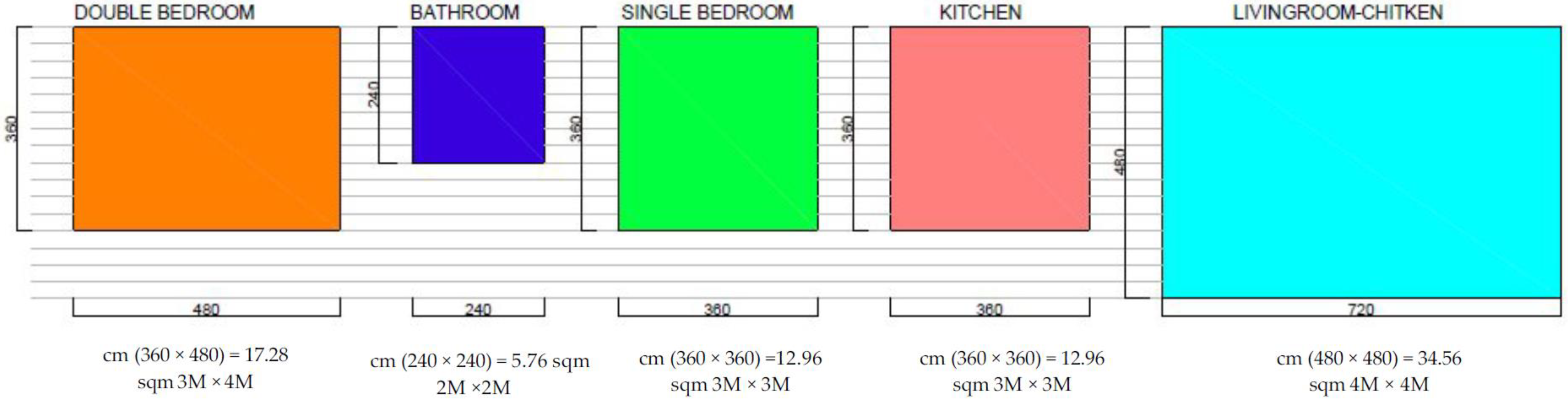
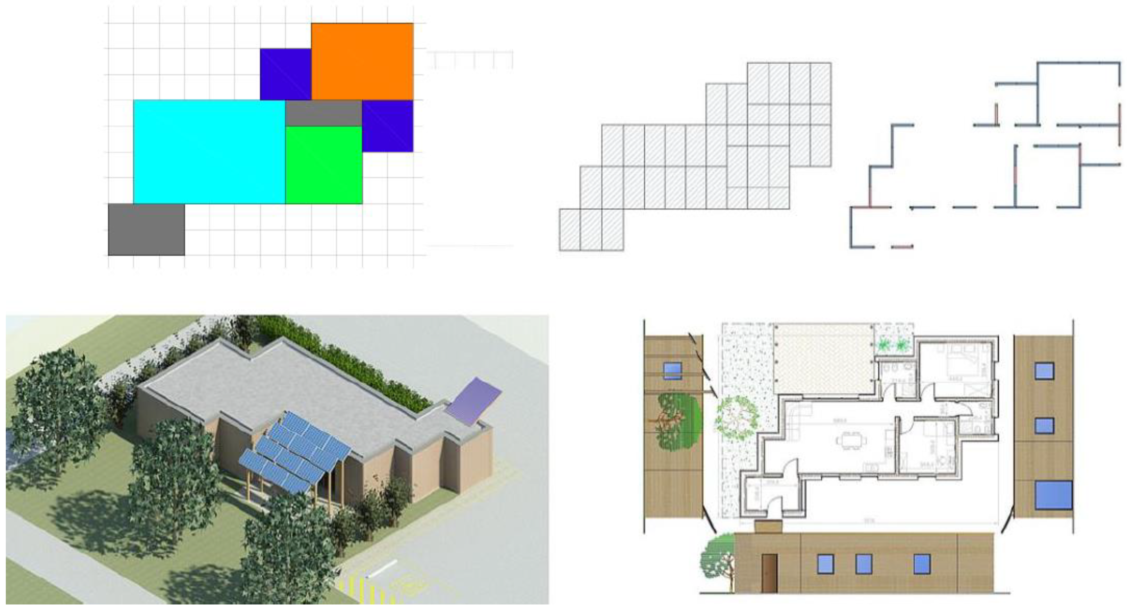
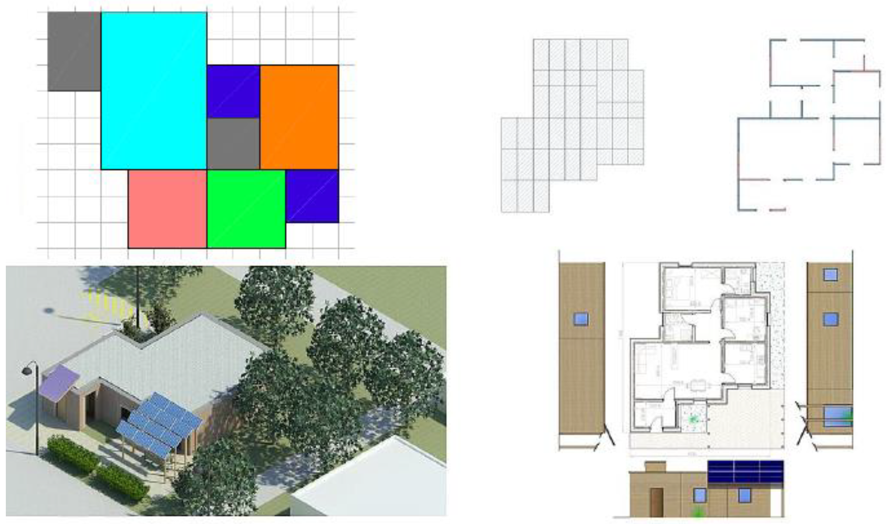
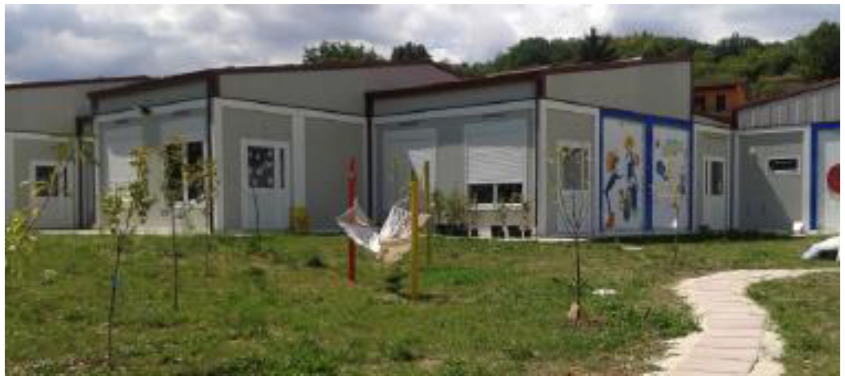
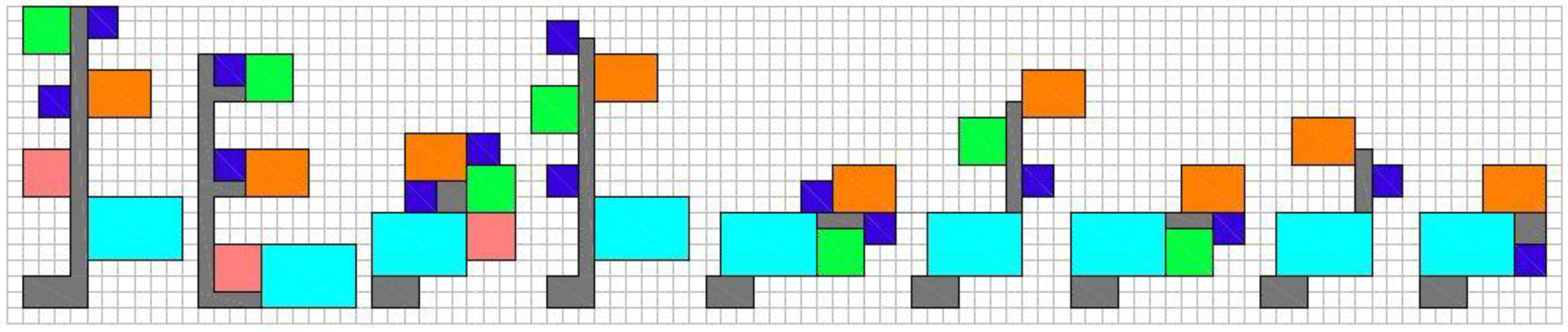
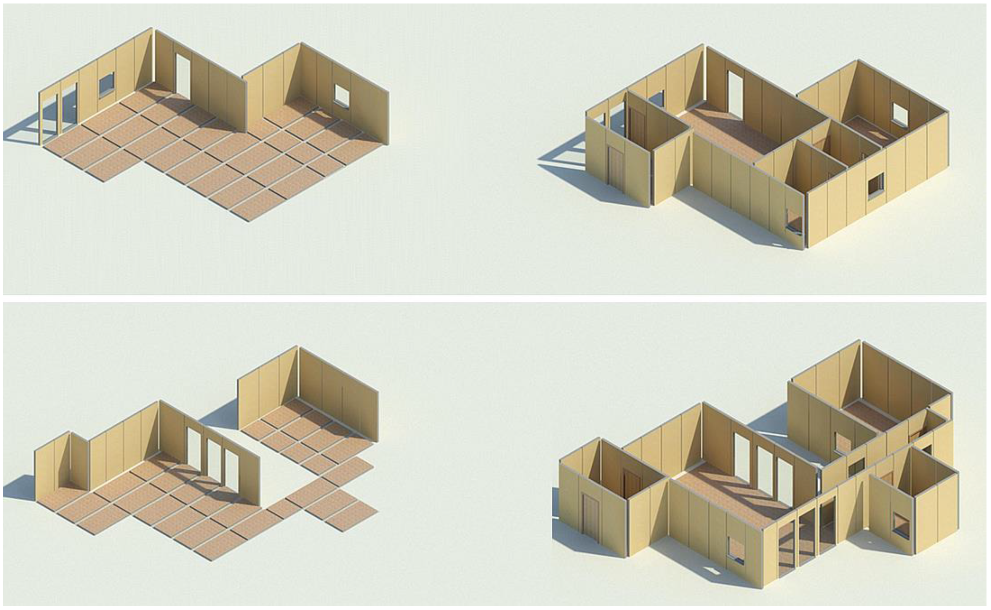
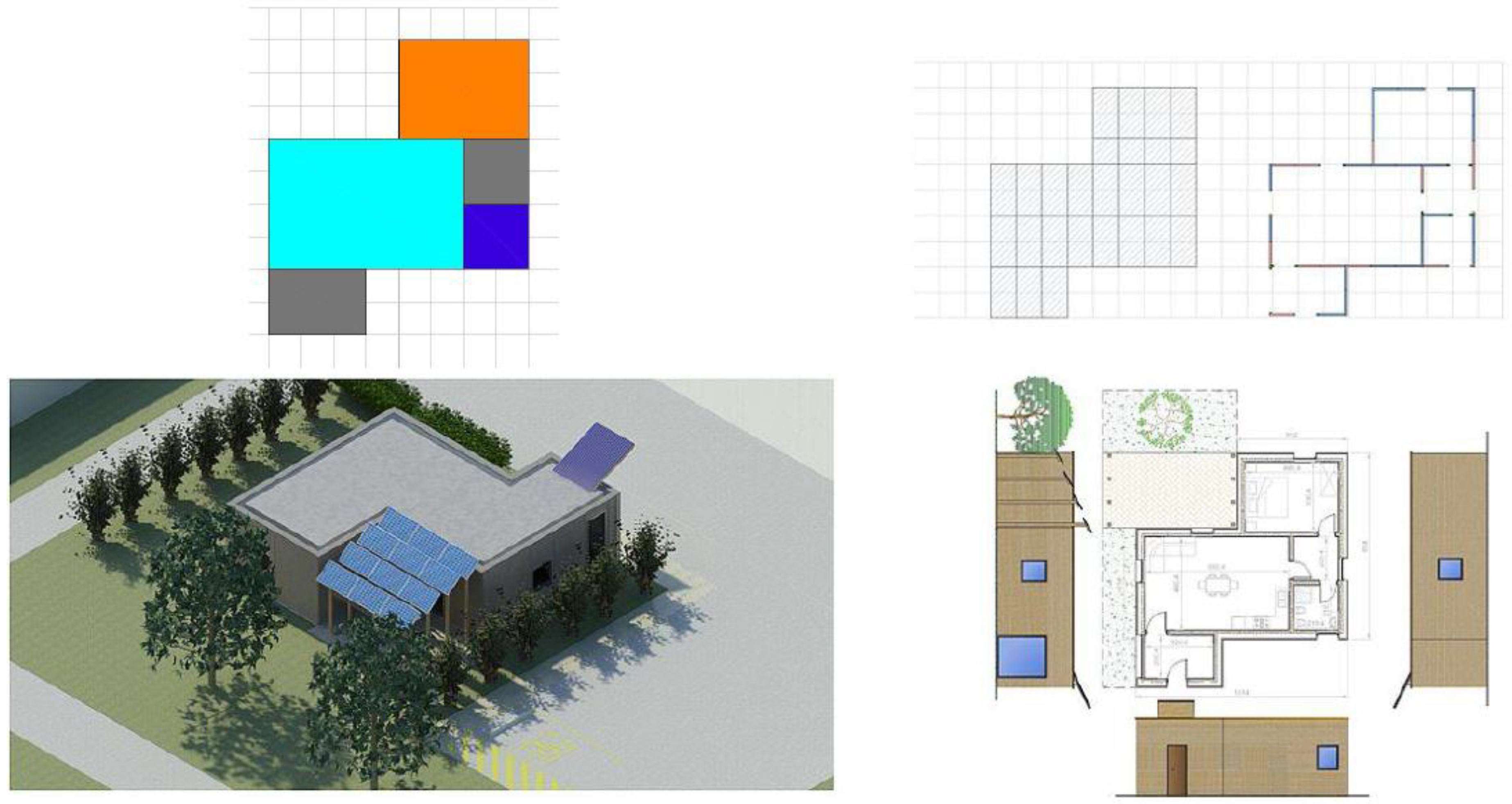
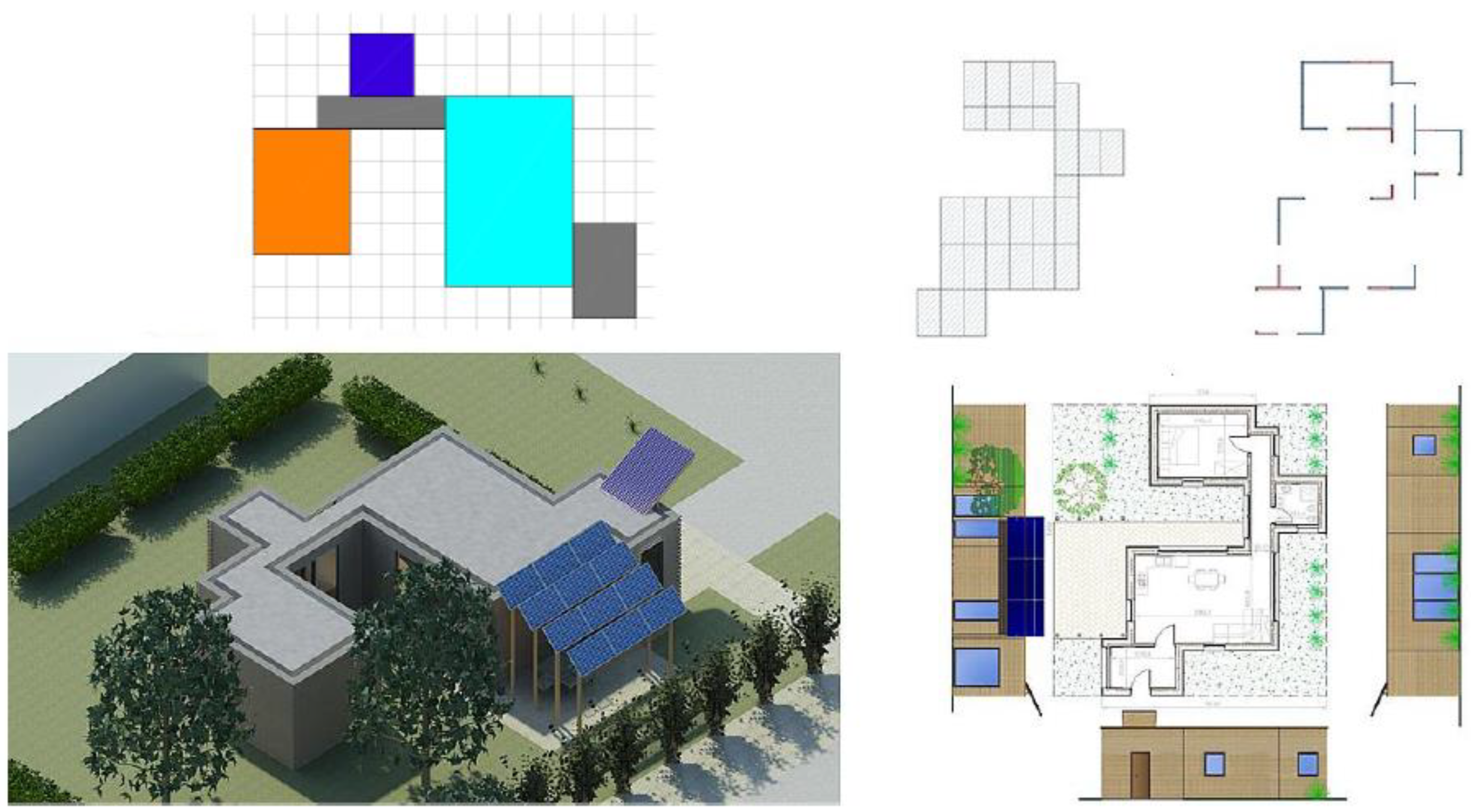
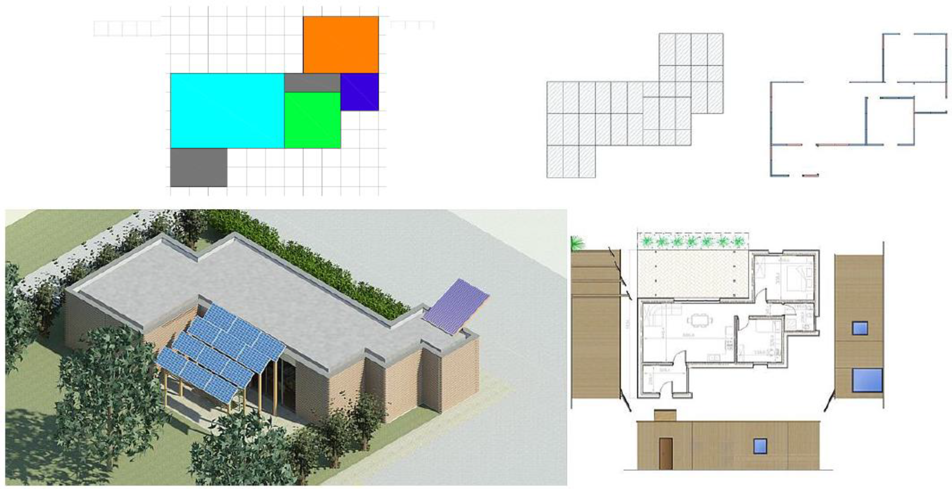
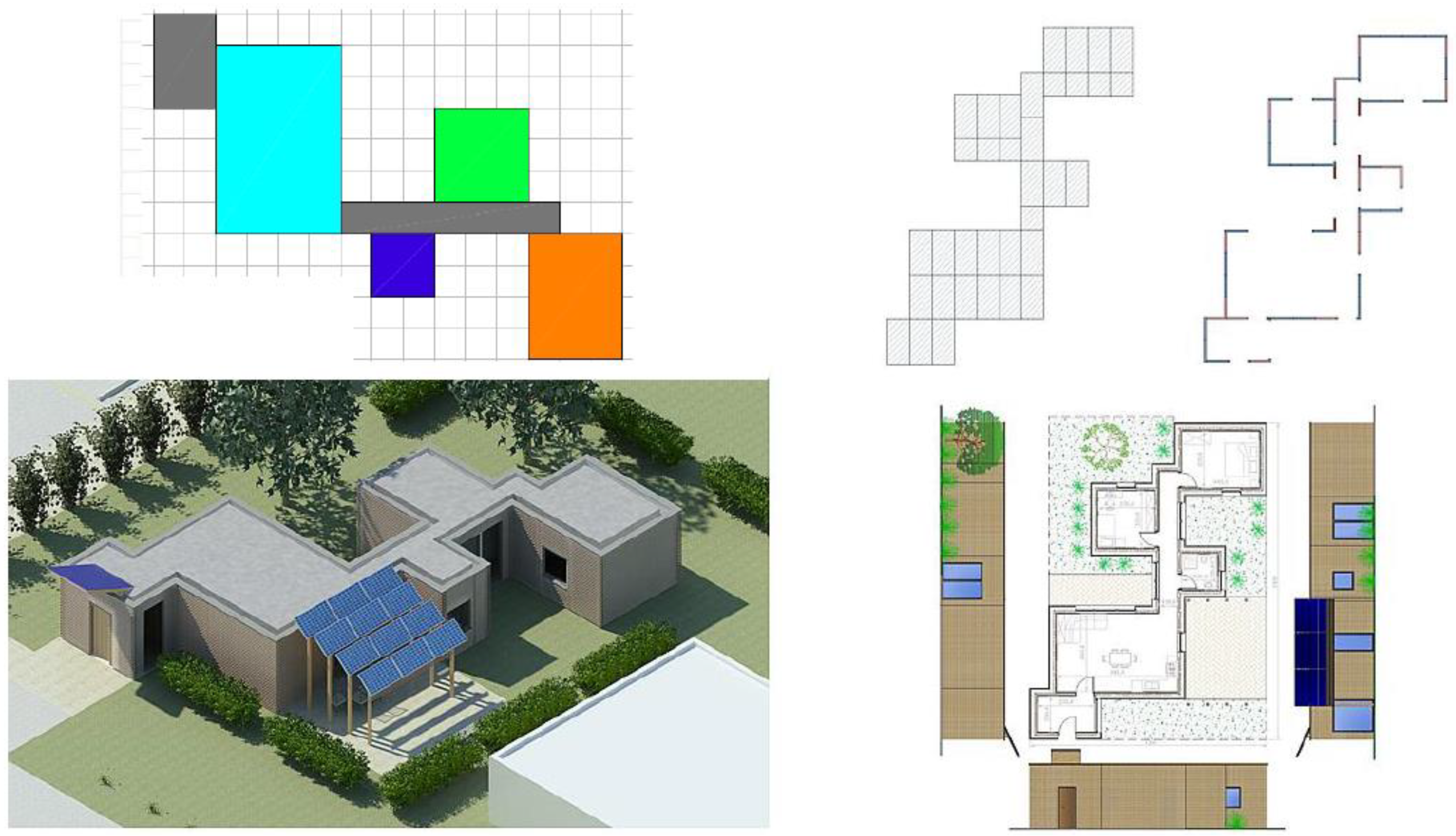
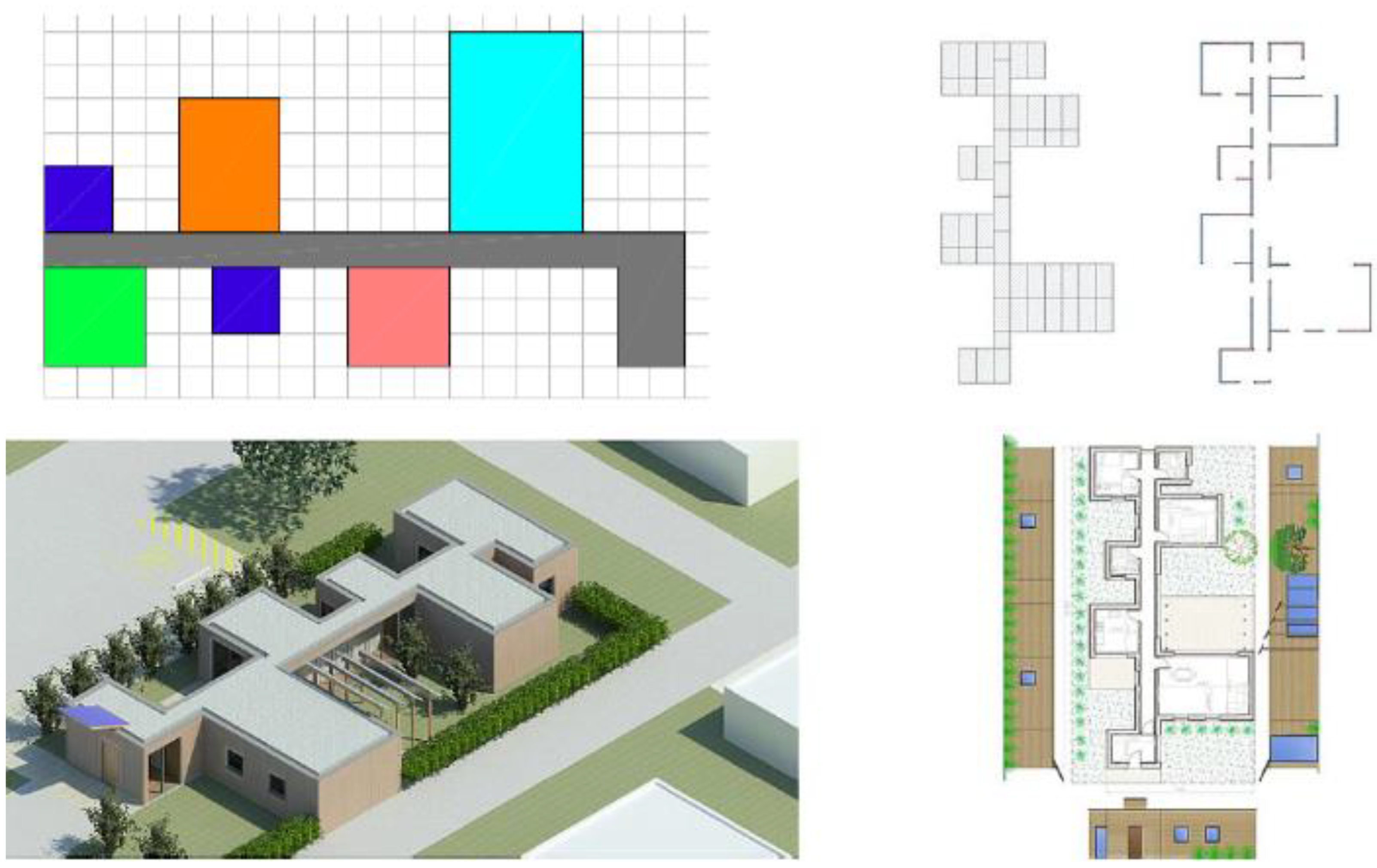
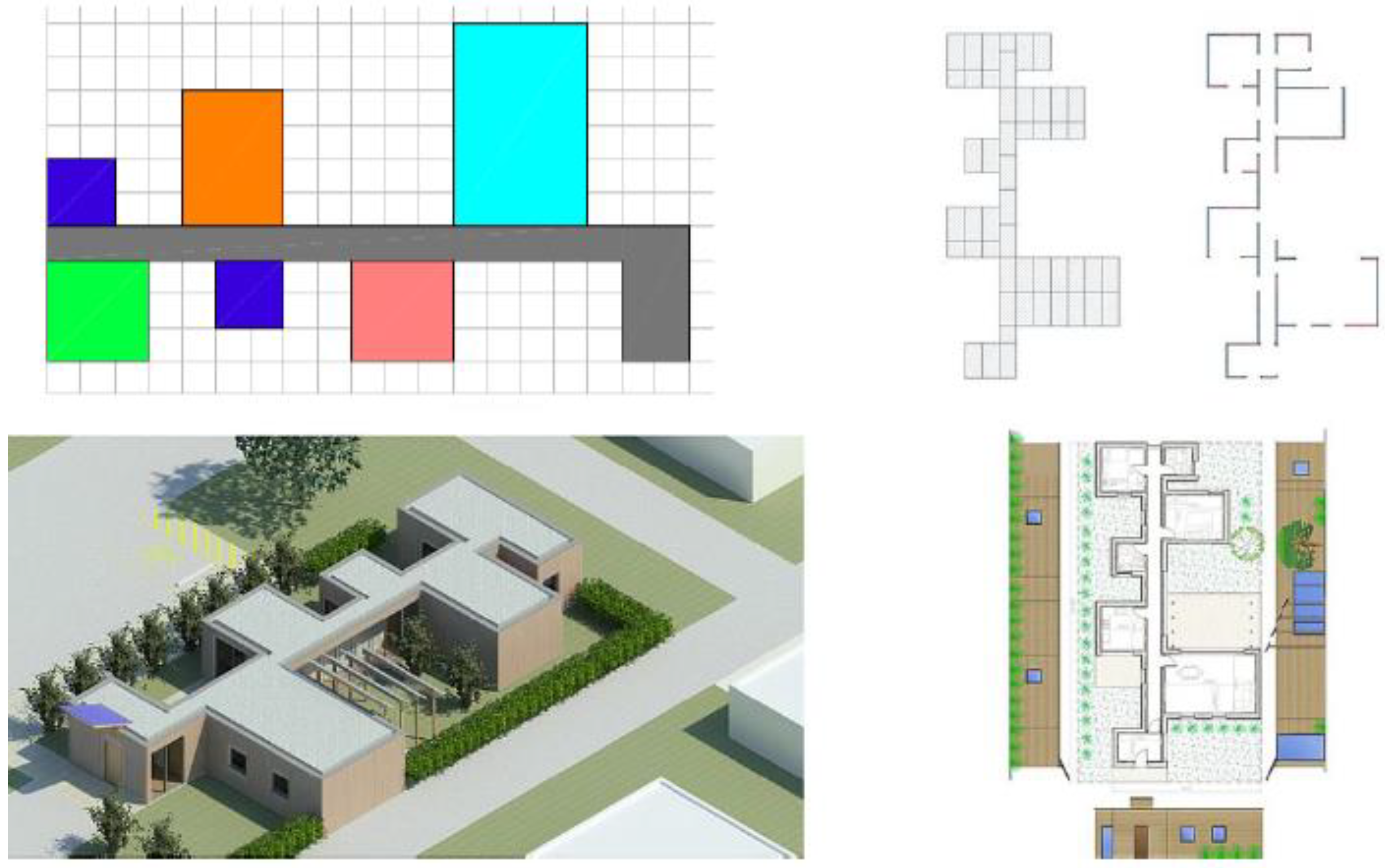
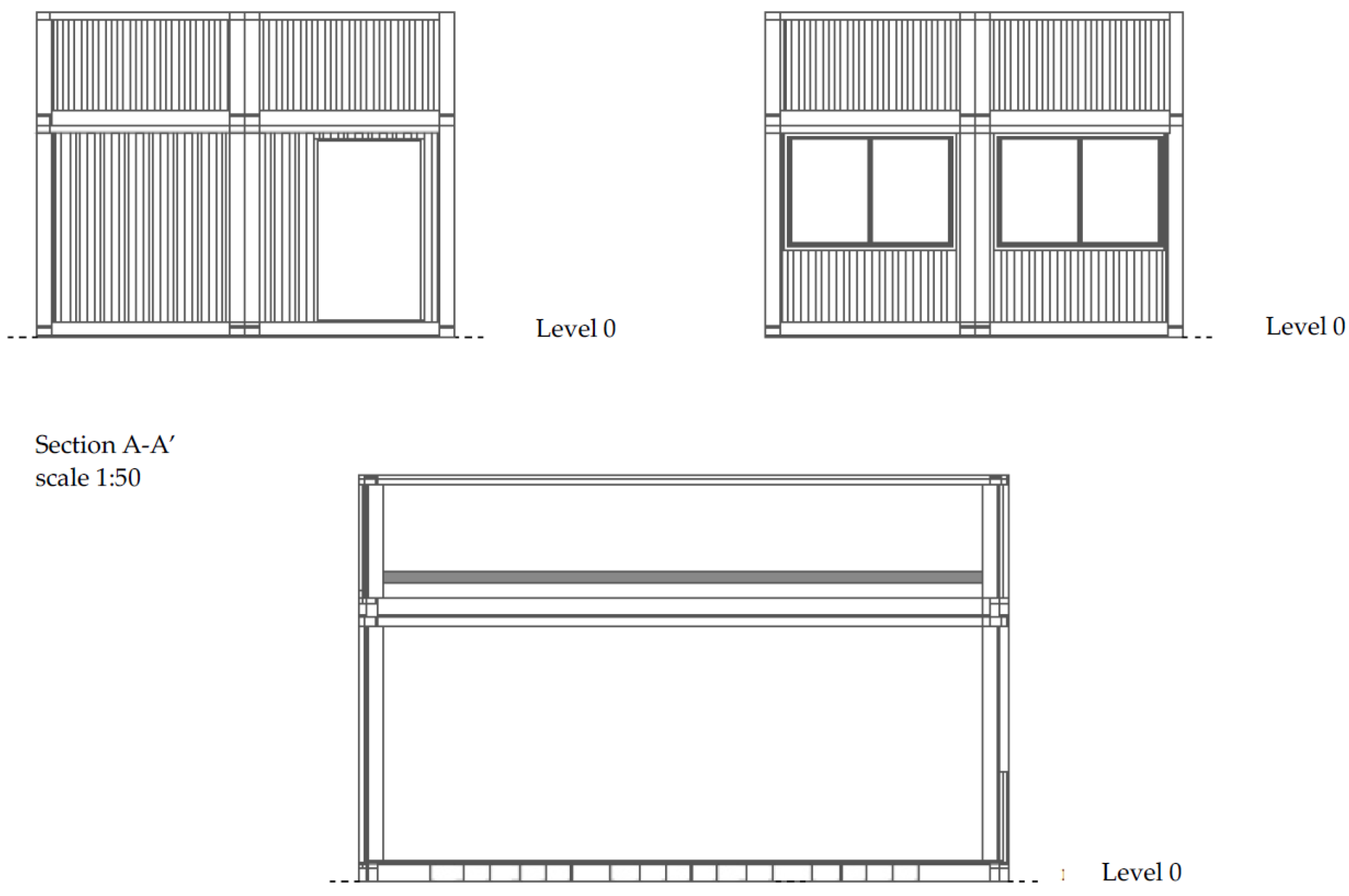
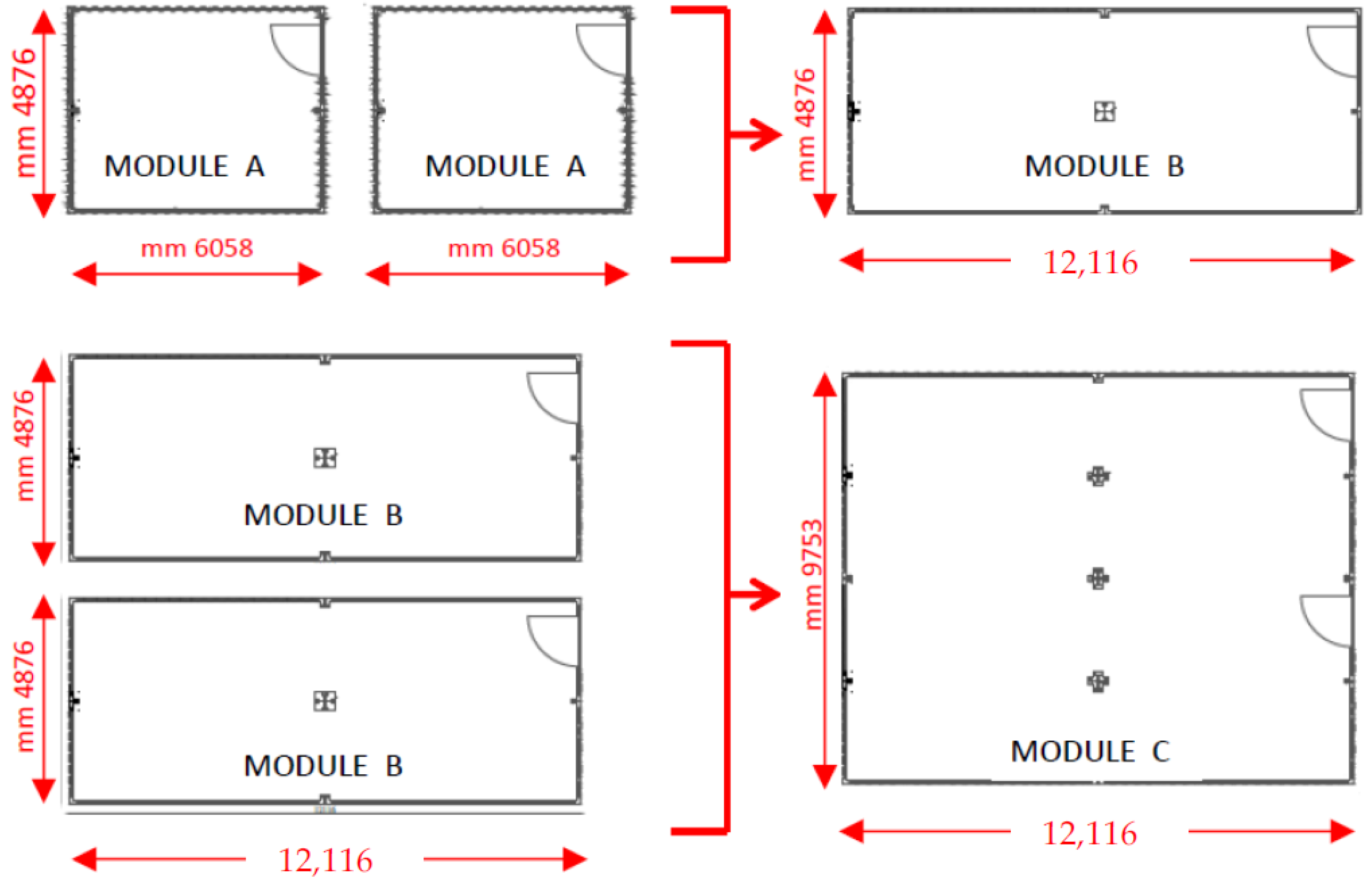
3. The Project Proposal: Standardized Modules and Different Types of Intended Use

The project proposals for temporary buildings [54] that can be implemented in an emergency [55] developed in this study concern housing [56], multifunctional [57], and sanitary intended use [58]. For the first two applications, the study identified the optimal technology to be used for modular cross-laminated timber (CLT) panels.
The identification of the module assumed the fundamental importance of the research. The concept of modularity, in fact, declined in the study under two different aspects: the functional–spatial modularity of the housing units and the technological modularity of the elementary component, the panel.
The search for the optimal geometry of the panel module was conducted with the following objectives: possibility of different assembly, to allow the realization of a range of solutions of housing modules able to meet the different needs of users; possibility of use in different emergency contexts [59]; and possibility of use of the same in different locations [60] and in different climatic contexts [61].
Another aspect of fundamental importance that the research considered is that of the speed of realization of modular systems. In order to satisfy this aspect, the study focused on the choice of the dry construction process.
Finally, another aspect considered is that of the transportability of the components of the system. As a result, a more in-depth study of the interaction between the dimensional choice of the panel module and the design concept of the emergency construction was necessary.
The results of this research generally contribute to the design quality [62], but above all, they have significant implications concerning the simplification of the construction process and the speed with which the works are carried out; consequently, the possibility of using this type of construction in a wider range of applications is increased.
Finally, the design paid particular attention to energy performance [63] and indoor comfort [64]. Temporary modules for both private and public use are commonly not sufficiently efficient in terms of energy [65,66]; this not only affects the operating cost but also has negative implications for indoor comfort.

3.1. Temporary Buildings for Residential Intended Use

The design proposal of temporary high energy efficiency housing modules identified a basic module of 120 cm (multiple of 30 cm) based on which the panels in plan and elevation were designed: floor panel and wall panel, see Figure 5. For the floor slab there are two types of panels one 120 × 120 cm and one 240 × 120 cm while in the raised four types of panels: a 120 × 300 cm base panel, a window panel, and two panels, type C and type D, and in combination form, the door and the respective shoulder pads.
The following considerations played a fundamental role in the dimensional choice of the component modules:
-
the possibility to have on the market a large number of producers able to meet any requests for contemporary production in large quantities as no special machinery is needed;
-
the possibility of finding large quantities of material needed for processing easily on the market.
The attention to these aspects has an economically advantageous fallout which contributes to the lower final cost of the system, as it operates in a competitive market regime.
From the study of the basic technological component “the panel”, we moved on to the study of the spaces of the environmental units. The spaces of five basic environmental units—the kitchen, the living room, the single room, the double room, and the bathroom—were designed; to these spaces of use has been added space with a function of transition between the external and internal environment. The spaces of the base units are designed both in plan and in elevation, using the modular design panels illustrated in Figure 5. Starting from these basic spaces, the study continued with the design of their aggregation, thus obtaining different possible housing solutions, as illustrated in Figure 6.
The environmental units can be composed in several ways, giving rise each time to a different housing unit, obtaining a high spatial and functional flexibility, and using different housing solutions. In fact, according to the needs of users and the climate conditions, it would be possible to forecast both the right number of environmental units and the aggregation forms in every kind of their types (compact or articulated), respectively.
Figure 7 shows how obtainable multiple residential types are.
Figure 8 shows the assembly diagram of an aggregate housing unit both in compact form (upper part) and in articulated form (lower part).
Figure 9, Figure 10, Figure 11, Figure 12, Figure 13, Figure 14, Figure 15 and Figure 16 shows the design solutions that can be traced back to four possible models, in a compact and articulated form.
The study dealt with the energy efficiency of temporary residences in the project phase. Considering this to be a relevant issue both concerning the amount of energy resource needed for the use of temporary emergency settlements, in which their reduction makes them more sustainable, and concerning comfort for users. The research foresees that the energy efficiency of the residences can be made optimal by passive systems, that is, by the choice of the technology of the envelope, whose elements, both vertical and horizontal, are made up of the structural panels in pre-and coupled with thermal insulation panels made of rock wool, and from active systems that is through the use of photovoltaic systems and integrated solar thermal panels, respectively, for the production of electricity and domestic hot water with electric generator heat pump. The technology for both vertical and horizontal enclosures is illustrated in Figure 17.
In order to obtain energy-efficient buildings, particular attention was paid to the stratigraphy of the opaque envelope as shown in Figure 17. For the transparent parts of the envelope (fixtures) the design thermal transmittance value Uw was considered to be 1.5 W/sqmK. Since the adopted solution of the casing in the project achieves high thermal insulation performance, in order to ensure healthy conditions and indoor comfort through the necessary air exchange, controlled mechanical ventilation with heat recovery is provided.
The energy performance check was carried out, which shows the same square meters of the building surface, the non-renewable energy performance index EP gl,nren of the compact form is equal to 3.41 kwh/sqm year, while in the case of the articulated form, the non-renewable energy performance index EP gl,nren is equal to 11.66 kwh/sqm year. This means that the geometric shape of the building plays a central role in achieving the objective of energy efficiency, with equal technological choices, layer thicknesses, and equal surfaces. In particular, it emerged that the use of the compact housing solution is more adequate in cold climates than in warm climates where the choice of articulated housing solutions is more adequate.
More generally, the study considers the architectural and technological design the focal point for reaching optimal performance.

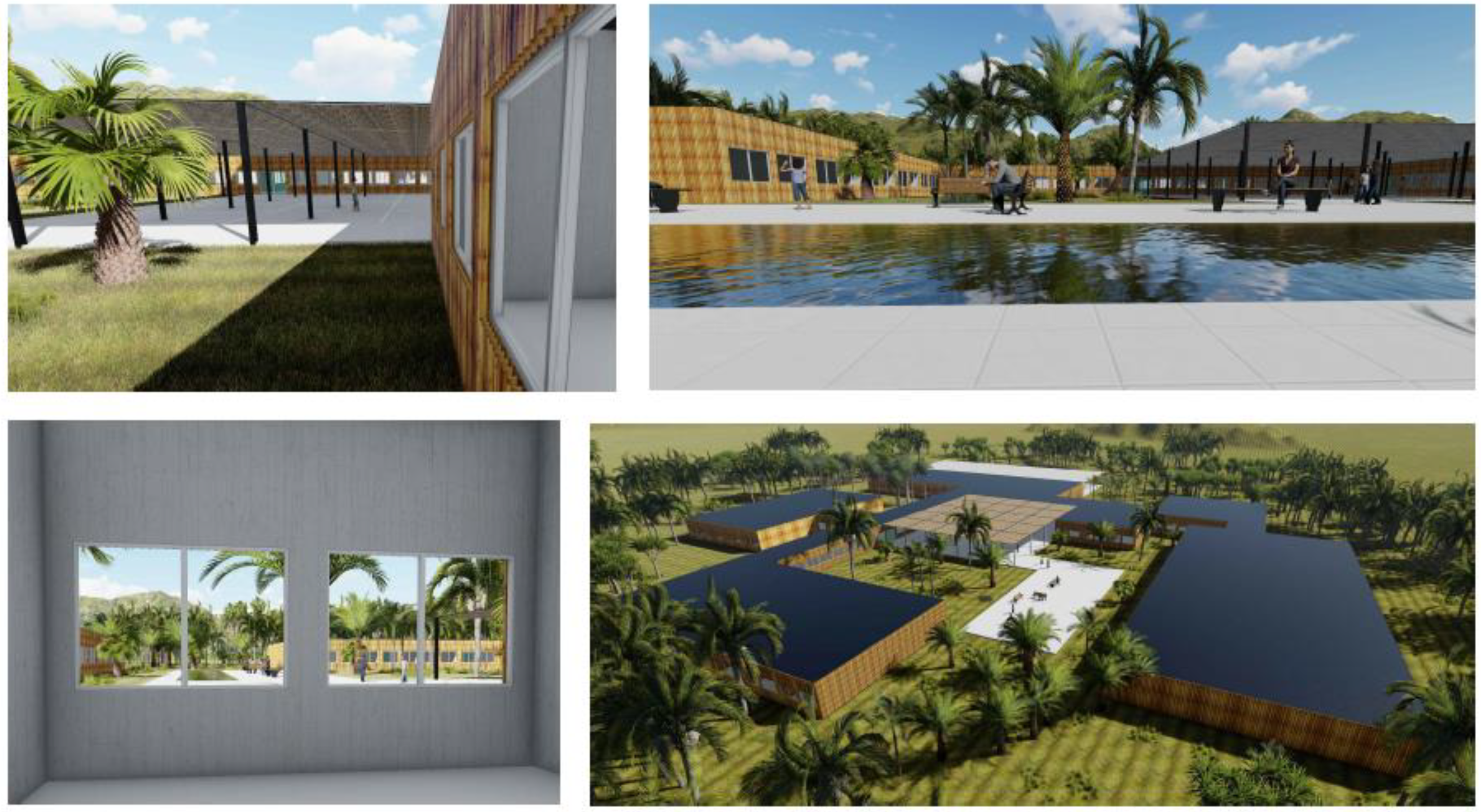
3.2. Temporary Buildings for Multifunctional Intended Use

The design proposal for temporary multifunctional buildings concerned the development of a modular system that was flexible regarding functional–spatial needs. The project proposal is designed to support services for intermodal transport, to be placed in public areas, such as waiting, ticket office, toilets, newsstand, and bar-cafeteria. However, although the system is designed for this specific use, it is conceived to be composed flexibly, to allow easy use for other possible uses such as housing and school.
In this section, only the multifunctional use is analyzed. The design proposal of the case study has a maximum footprint in plan equal to 15.19 m × 14.78 m; the spaces provided and their articulation consist, respectively, of a compass entrance, as a transition space between the exterior and interior to improve energy performance, a central space for the purchase of tickets, a waiting room, a corner for drinking, a sanitary room for users, in addition to the area reserved for staff, articulated in a room for the issuance of tickets, an office, a hygienic-sanitary room for staff, and a technical compartment for the location of the plants, as shown in Figure 18.
The horizontal and vertical structure is provided in CLT (cross-laminated timber) panels; the vertical panels have a thickness of 12.5 cm; and the horizontal ones are equal to 16.50 cm. This material meets the requirements of sustainability, is easily machinable, and also, with a suitable dimensioning of the modules, easily transportable. Figure 19 illustrates the position and the abacus of the four types of vertical panels—A, B, C, and D—and also shows the horizontal structure, both upper and lower, for which there are two types of panels, 16 of type A, with dimensions equal to 240 cm × 486.3 cm, and 6 of type B, with dimensions equal to 240 cm × 492.5 cm.
The project provides that the foundation technology unit can be built on poles, as described in Section 2.4; however, since the bearing capacity conditions of the soils, which may occur in situ are multiple, it is possible that in alternative such technological unit can be built on site. In this case, the standard solution provided is a reinforced concrete platform (Figure 20) with a thickness of 30 cm placed on a layer equal to 40 cm of granular cellular glass, which ensures both summer and winter a high degree of thermal accumulation.
This solution allows the elimination of the thermal perimeter bridge and, after the dismantling of the building, the stalls can be reused for other purposes. However, these are not incompatible with the module other foundation solutions, such as the continuous foundation with ventilated hornet’s nest and igloo (Figure 20). This solution has the disadvantage of being less rapid in the construction phase and, after the dismantling of the building in the event of reuse, requires the construction of a levelling jet, or, in the case of total demolition, work and execution times are more expensive than the previous solution; finally, from the point of view of energy containment, this does not allow an adequate thermal accumulation to obtain high energy efficiency.
As illustrated in Figure 20, particular care was given to the functional layers of closure; the insulation was mainly entrusted to a layer of wood fiber with a thickness for the vertical closure of 20 cm and for the horizontal closure of 22 cm, and an internal counter-wall plaster fiber and insulating glass wool with a thickness of 5 cm.
Particular attention was paid to the elimination of the thermal bridges of the ground connection through the use of extruded expanded polystyrene (XPS) (Figure 20).
On the southern front, there is a porch which has the function of rain protection and shielding. The energy requirement is provided by electricity in part produced by the photovoltaic panels placed on the roof. The planned systems consist of an electric invertible heat pump with the heat transfer fluid water for heating and cooling and an air handling unit for air conditioning only with heat recovery.
The sanitary hot water of the bathrooms is provided by a small independent heat pump to supplement the production provided by the solar thermal panels installed on the southern front of the roof (Figure 18).
The energy performance meets the requirements of the legal references currently in force on Italian territory and transposing European directives. Design researchers have tried to combine the formal and functional–spatial needs with the optimization of the same from the energy point of view. The volumetric and surface characteristics, the shape ratio, and the overall thermal capacity adopted are described below in Table 3.
Assuming the use of the module in different locations of the national territory and in different climatic contexts, the study provided for performing energy simulations in different locations of the Italian territory including Padua, Rome, Bari and Naples, in order to verify performance as reported in Table 4.
For each locality, the annual electricity demand was calculated for artificial lighting, heating, cooling, and domestic hot water. The total amount of the demand for the places considered in euro was quantified (at the current cost of energy) as summarized in Table 4.
For reducing electricity demand from the grid, the use of photovoltaic panels and solar thermal panels is foreseen in Table 5, which summarizes in % the coverage of the annual needs due to this location-by-location strategy, quantifying the production of the solar thermal system and the photovoltaic system. In addition, for each location, the amount of primary global energy needed (row 3) is shown, in addition to the production of energy due to renewable sources (row 4), and, finally, the residual electricity that must be taken from the network (row 5). It was observed that the values of kWh/sqm year are extremely low, especially for the towns of the center south.

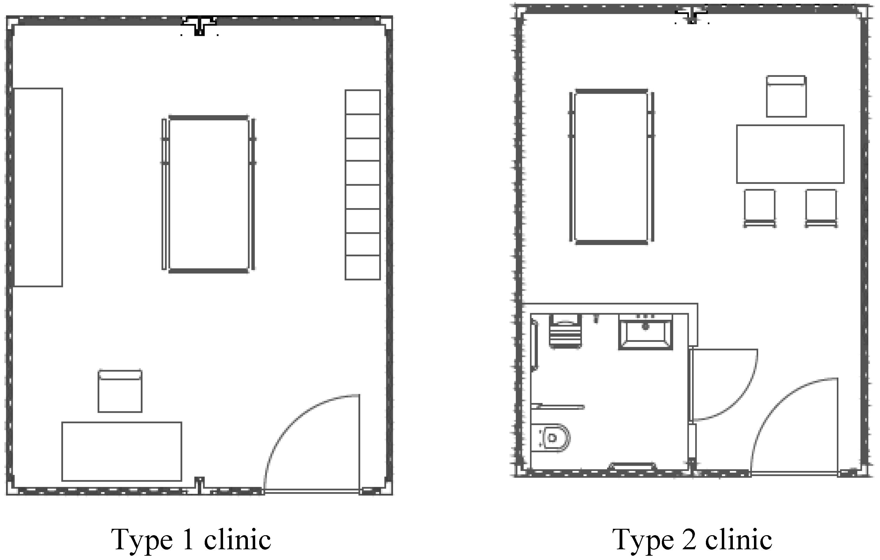
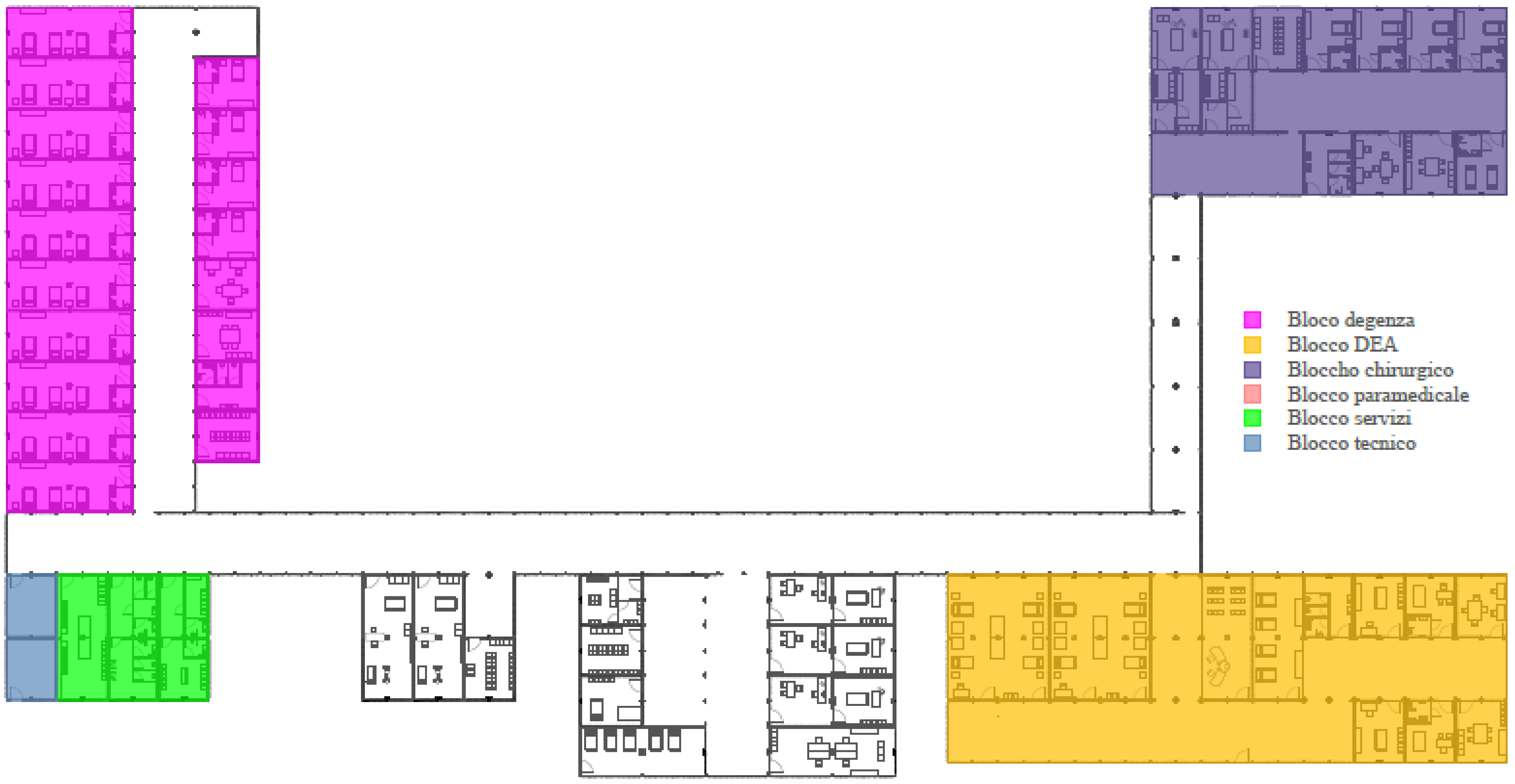
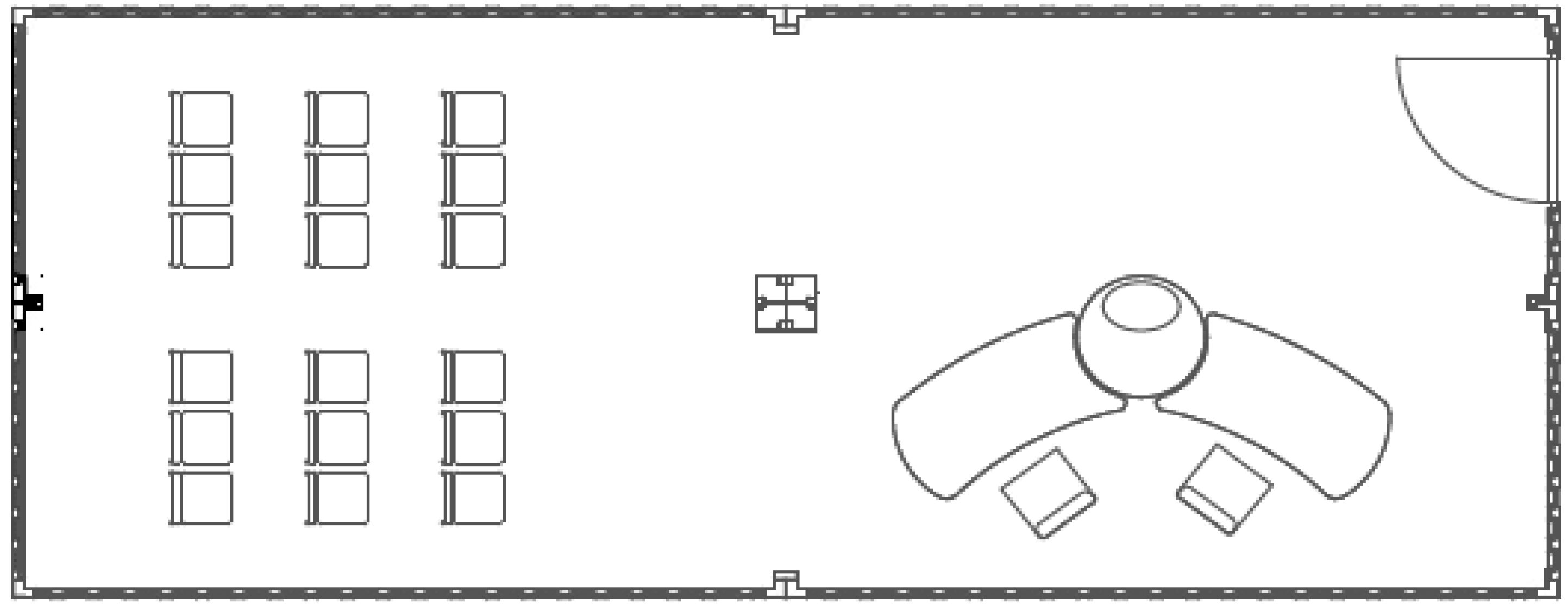
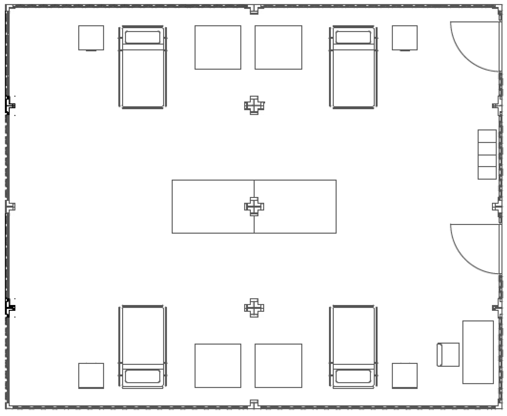
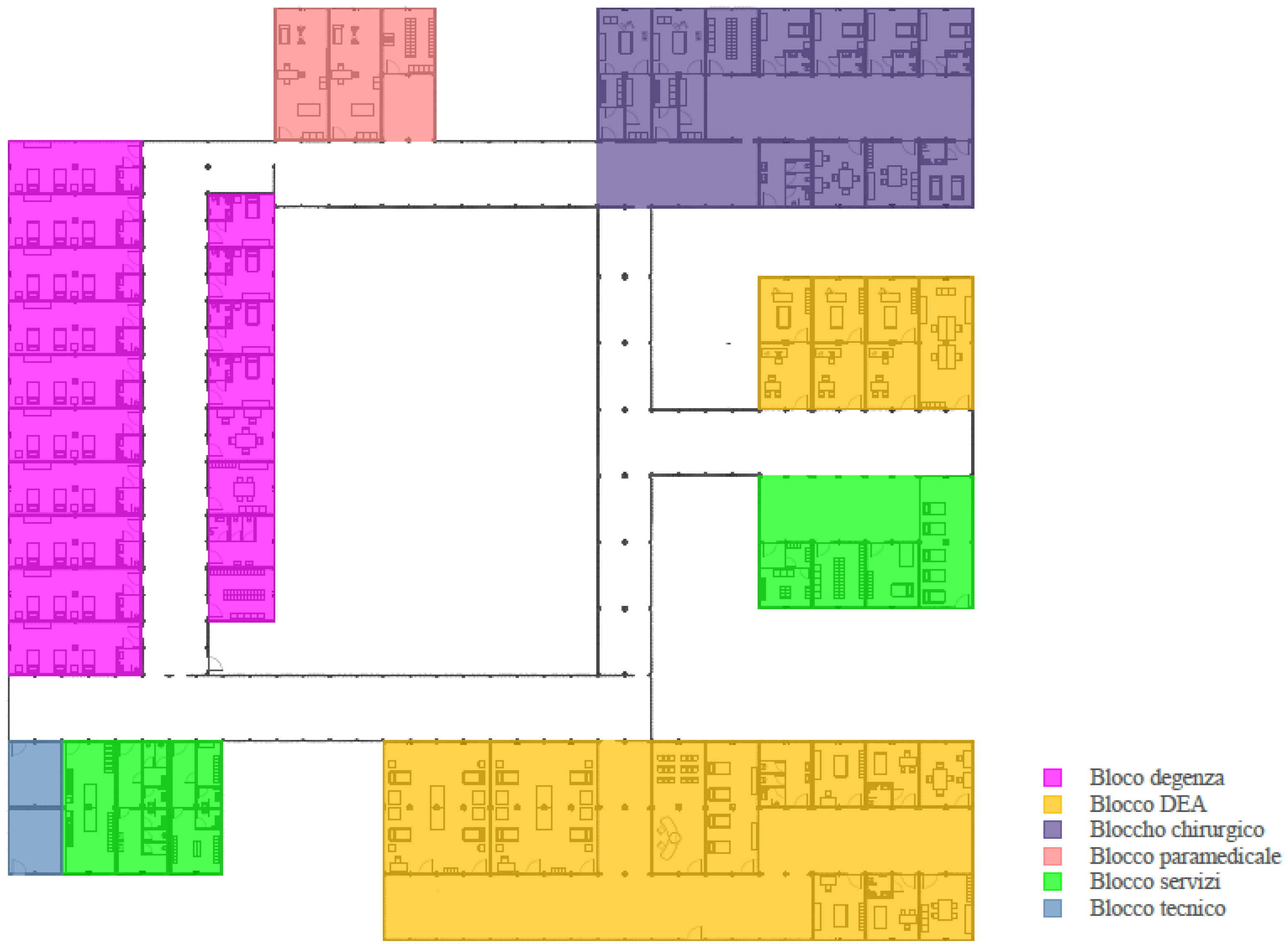
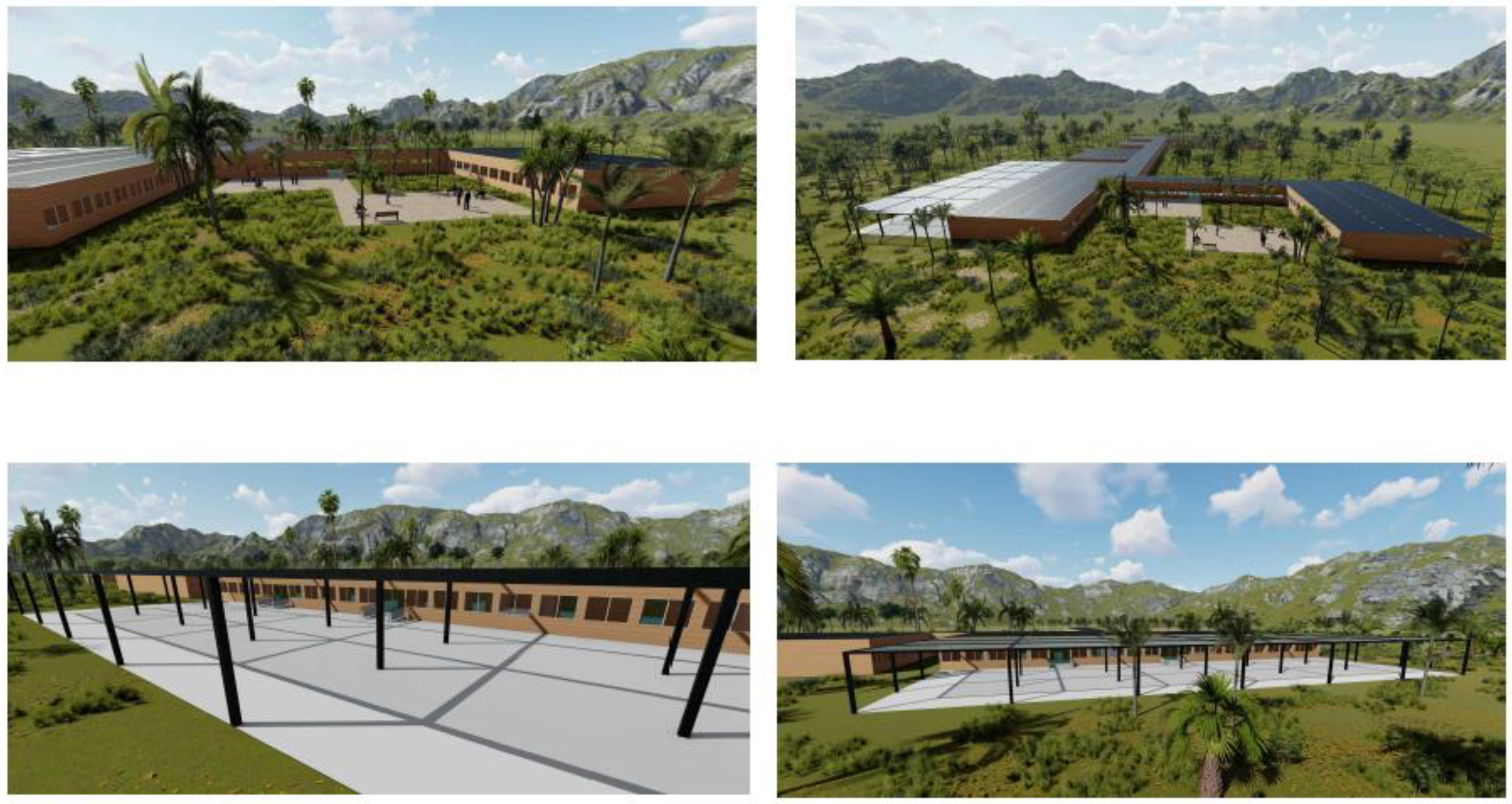
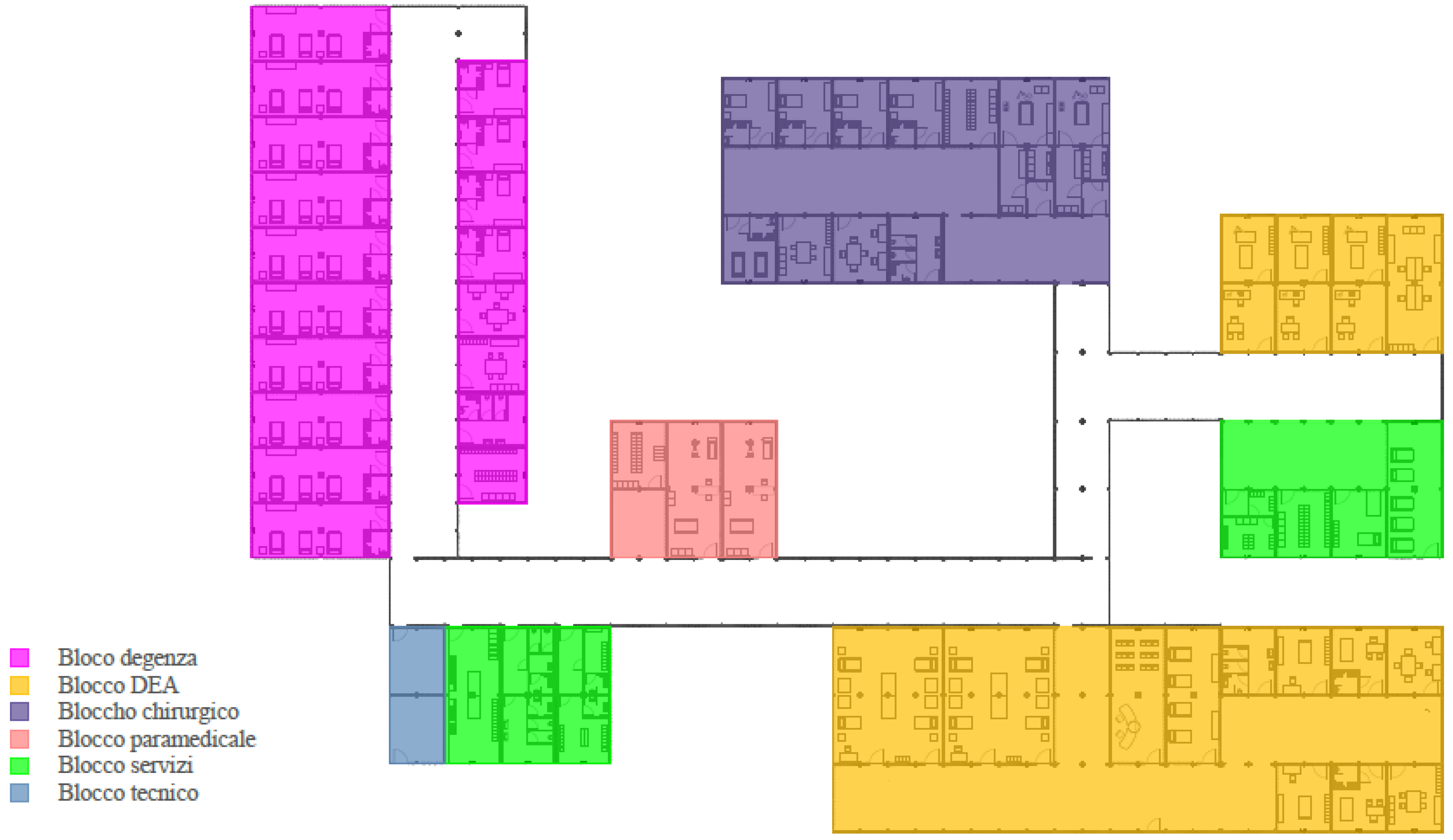
3.3. Temporary Buildings for Hospital Intended Use

The project proposal concerns temporary buildings intended for re-usable healthcare in emergency scenarios [67], including in armed conflicts [68]. These are recurring and world-wide emergency scenarios [69]. Within this theme, the study shows how it is possible, starting from the project requirements set out in Section 2, to create a building structure [70] capable of dealing with the health emergency [71] caused by the explosion of landmines in post-war theatres. It is sufficient to consider that this phenomenon involves, on a worldwide scale, one third of the states, and moreover, that mines are the leading cause of victims in conflicts, and finally, that this problem is not limited only to the duration of armed conflict but, because of the dissemination of these explosives in a territory, there are still many victims for many years after the end of hostilities [72]. It is therefore considered necessary to think of an ad hoc health facility.
In this case, too, the design proposal is based on the research of the module. It must be aggregated, thus allowing us to obtain complex functional–spatial articulations, and the differentiation of the interior furniture that can be predefined for each module, depending on the function of the same within the functional blocks. The basic module capable of satisfying these characteristics was considered to be the container. It satisfies both the characteristic of transportability and easy displacement; its structure is relatively light and easily adaptable to the needs of internal use; moreover, it allows the realization of more complex functional–spatial structures.
The single module is repeatable and allows the creation of multiple combinations according to different needs, and also considers the fact the existing containers are characterized by modular structures that allow the creation of structures that can be opened on different sides, depending on specific design elaborations. Therefore, to characterize the typology more appropriate to the planning elaboration, this study analyzed the geometrical characteristics of the existing containers in commerce.
On the market, there are four categories of containers of standard dimensions, designed for transport and handling, namely, the container box, the high cube container, the open-top container, and the flat rack container. As explained and illustrated in Section 2, the project research identified three modular structures: A, B, and C. Modular unit A was obtained from the dimensional configuration given by the flanking of two open-top 20′ containers, at the major side, with the elimination of the two adjacent side walls, as described in Figure 21.
Modular unit B was obtained by the addition of module A at the lower side, using a total of four open top 20′ containers, in this case also with the elimination of the adjacent internal walls, as seen in Figure 22.
Modular unit C was obtained by the addition of module B, at the lower side, using a total of eight open-top 20′ containers, in this case also with the elimination of the adjacent internal walls, as shown in Figure 23.
Regarding the height of the module, to comply with the regulatory requirements of minimum internal height of the premises and also obtain a functional space for the plant, the design study plans to modify the open-top container. The modification consists of superimposing the same structure with the same dimensions in planning and having an equal height of 115.7cm, as can be seen in Figure 24.
It should be noted that this maintains the same characteristics as the requirement for transportability. The modules can be transported individually and then assembled and set up on-site.
The open-top 20′ container, which, depending on the module, can be aggregated in different multiples, is planned in three conformations: with two walls, one closed and one with openings; with two walls, both closed; or with a closed wall and a wall equipped with door.
The piece necessary to ensure the internal height of the project reaches a height of 115.7 cm, it is always equipped with a roof, and it is provided in configuration with two closed walls. The measurements of the three modules A, B, and C, identified as repeatable design structures, are shown in Table 6, while the dimensional ratios between them are shown in Figure 25.
The structure of the module consists of a base divided into two parts: the supporting frame and the floor. The frame is made with four steel C-shaped perimeter profiles, facing outwards, and C-shaped steel beams arranged transversely concerning the length of the base module. There are also four welded angular steel elements equipped with a 6 mm thick eyelet for lifting. The floor above the members is made of plywood treated with phenolic resins with a thickness of 21 mm and a PVC sheet with a thickness of 2 mm, as illustrated in Figure 26.
The perimeter vertical closures consist of four uprights (angular profiles) in steel with a thickness of 6 mm and self-supporting vertical trapezoidal sheet. The insulation of the casing is made of a high-density polyurethane foam contained between two hot-dips galvanized sheets with a thickness of 4 mm; the total thickness of the closure is 76 mm corresponding to the major side and 87 mm corresponding to the minor side of the module, as shown in Figure 27.
The internal partitions are made in the same way as the vertical closures, having a total thickness of 10 cm or 12 cm if they act as a plant housing. The upper horizontal closure consists of the frame and cover. The frame is made of welded steel profiles with a thickness of 3 mm, while the cover is made of self-supporting corrugated sheet with a thickness of 1.2 mm, as shown in Figure 26 and Figure 27. The false ceiling consists of sandwich panels in high-density polyurethane foam contained between two sheets of 4 mm galvanized, with a thickness of 12 cm, welded to the perimeter beams.
Having identified and described modules A, B, and C of the project from the geometrical and structural point of view, possible functional–spatial compositions are now outlined, depending on the specific needs of the premises of the sanitary facility. Examples of functions that can be appropriately placed in Type A, Type B, and Type C modules are presented.
The type A module can respond to the need to find suitable spaces for the clinics, as can be seen in Figure 28. The figure illustrates two types of practice. The medical clinic (type 1) is used for visits to patients prior to an intervention or to verify the path of healing and discharge. Inside this room, there is a patient bed, a desk with seats, and furniture accessories such as cabinets and shelves for sanitary equipment and storage of any equipment. Surgical surgery (type 2), although it is not an operating room, is the one where one intervenes in the patient to perform small operations and minor dressings.
This module features a cot with enough working space for healthcare personnel, dedicated toilets, a desk with seating and cabinets, and accessory shelving for the storage of sanitary equipment, monitors, and other equipment.
The type B module can respond to the need to find adequate spaces for first aid in green or red areas, as shown in Figure 29.
The type C module can respond to the need to find adequate spaces for first aid in the red area, as shown in Figure 30. This room is used for intensive emergency care dedicated to patients evaluated in red code by the triage of the emergency room. It hosts spaces for patients’ beds, with suitable space for use and passage, the space to allow the necessary monitoring to each, the space for the position of the doctor–nursing, so that the operator can constantly check the state of the course of the patients, the space for a desk with a seat dedicated to the doctor, and auxiliary furniture such as cabinets for equipment and medical devices.
Three possible healthcare solutions demonstrate the flexibility of the design choice. Each example consists of the assembly of modules A, B, and C of the project and the use of local materials for the finishes and exterior coverings, which are only examples and may vary depending on the territorial context in which you work. Morphology and geometry of the structure are examples of how different structures can also be realized in function of the climate and territory. The three structures were set in climatic areas with tropical, subtropical, and desert climate.
In Figure 31 and Figure 32, the floor plan and the renderings representative of the first sanitary structure are illustrated with the arrangement of the modular elements, the functional blocks, and the connections between these.
In Figure 33 and Figure 34, the floor plan and view are representative of the health care solution 2.
In Figure 35 and Figure 36, the floor plan and views are representative of the third possible sanitary structure solution designed.
In a similar way to the other design solutions for the emergency, also for that one dedicated to healthcare facilities, this study set itself the goal of thinking about energy-efficient solutions both for reasons of comfort and to minimize consumption. It was decided to study, from the point of view of energy analysis, the ten states recognized by the WHO (World Health Organization) as being most affected by the emergency of landmines. The countries in question are Somalia, Mozambique, Egypt, Afghanistan, Angola, Bosnia and Herzegovina, Kuwait, Cambodia, Iraq, and Iran.
They were also divided into smaller areas, if the climate of the territory differed particularly from one area to another, while they were studied as a whole if there was a sufficiently homogeneous climate. Having analyzed the climatic specificities of the different countries under consideration, it was decided to carry out the energy analysis on module A, module B, and module C, considering the most energy-intensive project characteristics for each one, to perform a cautionary energy simulation concerning real consumption. The three modules were analyzed in each of the above regions.
The conditions for the analysis of the module are as follows:
-
it is considered isolated because it can be used individually and therefore with four exposed walls;
-
minimum external air exchange volumes in the number of 5 and minimum hourly air changes in the number of 25 are provided;
-
a maximum relative humidity of 30% and an expected internal temperature of 26 °C are considered;
-
the following lighting characteristics are assumed: the design illuminance of 1000 lux, the UGR (unified glare rating) of 19, the uniformity of illuminance of 0.60 and the color rendering index of 90, or the minimum values of the operating room;
-
the operating consumption of the machinery is taken into account by referring to the consumption of the TAC, which is a machine of constant use with higher consumption or daily consumption equal to 113 kwh for 24 patients per day.
The same plant characteristics for modules A, B, E, and C are as follows: controlled mechanical ventilation with double flow. The system is able to treat, filter, heat or cool the outside air, ensuring the constant exchange and the recovery of the heat of the exhaust air. The advantages of this type of system also include control of the air flow, the possibility of using a heat recovery unit, the possibility of control over the quality of the air renewal, and the control of air velocity in the environment. The ventilation and heat recovery unit have a remote control of the recovery and automatic control of summer free-cooling and winter free-heating. It has a capacity of 172 mc/h and a housing area of 50 sqm. The air conditioning of the rooms is guaranteed a mixed air–water system because it is a system suitable for use in fractional structures in different environments, where a targeted regulation can be carried out in a single room. The air participates in the control of humidity and the filtration of the plant, while the water feeds the thermal exchange of temperature of the rooms.
We use systems with low values of difference between the temperature of the fluid and that of the environment or radiant systems that, combined with the system of controlled mechanical ventilation, ensure the right cooling down, cooling, dehumidification, and purification. The system planned in the project is the radiant ceiling system installed in the false ceiling. The ceiling fan coil have a heating power of 10 kW and a cooling power of 7.2 kW, equipped with polypropylene filters. The dimensions are 298 mm × 569 mm × 627 mm.
The system is powered by an air–water heat pump composed of an external generator placed in a special technical compartment, where the fluid at very low temperature can absorb heat from the outside air. The latter is then subjected to compression and condensation inside the plant, and consequently, its temperature is significantly increased. In this way, when it arrives at the internal unit, the fluid releases the accumulated heat, heating the water in the pipes. The envisaged heat pump has a minimum heating capacity of 2.8 kW, maximum of 5 kW, and nominal of 5 kW; for cooling, it has a nominal capacity of 4.5 kW. The dimensions of the outdoor unit are 740 mm × 950 mm × 330 mm. The energy analysis was carried out with the Termus software (Vers. 42.00, ACCA Software S.p.A, Avellino, Italy) [73] because it allows one to insert all the input climate data manually. Assuming that for each module, A, B, and C, the goal was to achieve the energy class A++, following the European standard, the minimum surface area, and, consequently, the relative number of photovoltaic panels to be installed to be able to satisfy the energy requirement in order to guarantee the energy class indicated above was performed for each area studied. It is planned to install high-performance monocrystalline silicon photovoltaic solar panels with a copper base that allow more energy to be converted over time; the dimensions of the single panel are as follows: 1168 mm long, 998 mm wide, and 46 mm thick, with a peak power of 360 W.
Table 7 shows the energy analysis in the different regions and the relative number of photovoltaic panels in module A. The same is in Table 8 for module B and in Table 9 for module C. The energy assessment is made considering the normal energy uses in hospitals, precisely an average of 0.38 kWh/m daily, corresponding to 12.16 kWh daily for Module A, 22.45 kWh daily for Module B, and 44.9 kWh per day for module C. To meet the needs of large hospital equipment such as magnetic resonance imaging and CT scans, which each consume up to 113 kWh per 24 patients per day, a number of photovoltaic panels whose surface area is greater than the available area of the module’s coverage are required; so, in order to allow the module falling into energy class A++, an extra number of panels will be required, which must be installed on the roofs of the adjacent modules. Table 7, Table 8 and Table 9 provide the number of panels to be installed according to the localities concerned.

4. Discussion and Conclusions

The above research aims to contribute to the sustainable design of temporary buildings in emergencies, and is divided into two fundamental parts: on one hand, the analysis and identification of the requirements that must be placed at the base of the design research described in Section 2, and on the other, the real design experimentation is described in the case studies. The first part starts from pre-project considerations and is based on the study of the criticalities and deficits found in actual emergencies.
The second part more specifically concerns the design. It is more articulated, translates into the project, and develops the requirements identified in the first part of the study, such as settlement in the territory, energy efficiency, transportability, and reuse, assumed in the project proposals. It proposes a range of possible solutions, each with their own specificity and originality of response, both from the technological–constructive point of view of the techniques and materials, and from the point of view of the underlying theory of prefabrication. This last one, historically, was born and consolidated starting from two conceptual lines: parts or models. The first was theorized by Gropius, the second by Le Corbusier [74].
In the first two case studies, the CLT was chosen as a prefabrication material because of its sustainability characteristics. In these two case studies, the satisfaction of the requirements leads to the development of design research in the identification of basic technological modules, to be produced in prefabricated form. It is a development of the philosophy so-called by parts.
The search for the geometry and therefore the correct dimension of the basic modular elements is complex because its identification represents the intersection set of different fields. The first field is related to the speed of production and its cost, which requires that the abacus of the pieces is limited. For example, producing more parts means taking more time and more cost of production; it also has repercussions on the ease of assembly on-site: the more diversified the abacus of the more complex parts will be the assembly operations. A second field is tied to the optimal exploitation of the space of the means of transport in which these pieces will be allocated: the container. A third field is linked to the time of assembly: in fact, the smaller the size of the base module, the more time will be require for the assembly in situ; but at the same time, on the other hand, this will better facilitate handling, especially in inaccessible areas. A fourth field is related to the composition of the technological modules in plan and elevation, to allow the composition of the spaces of the different environmental units and their aggregation to form different housing units. The third case study, in which it was chosen to use the container as a prefabricated modular element suitably modified and equipped inside, is a development of the so-called philosophy for models. In this case, there is the search of the base module, but the latter is not two-dimensional, but spatial.
The search for the basic modular elements is, however, also in the latter case, complex. The complexity is different from the first two cases because it is exclusively linked to the functional use of the spaces. It allows a higher mounting speed than the previous cases. It is characterized by less flexibility of the spaces that are predetermined by the minimum size of the container chosen as the basic module, that is, the minimum modular unit. In the case of emergency buildings for hospital use, however, the possibility of equipping the basic module in the factory and the possibility of transporting it directly as a container itself allows us to minimize the assembly and disassembly times of the sanitary structures for the emergency and, at the same time, guarantees the rapid activation of hospital operations. In all the case studies, the design issues related to the fulfillment of the requirements, in the particular settlement in the territory, transportability, and re-usability that refer to aspects of ease and timing of installation, played a fundamental role and were the starting point for the design development of the technological modularity of the prefabricated elements, which could then be coherently combined with the research of functional–spatial modularity. Future development of this research could be oriented to the deepening of the cost analysis; here, this is not specifically addressed.

Author Contributions

Conceptualization, R.P. and M.C.; methodology, R.P. and M.C.; validation, R.P. and M.C.; formal analysis, R.P.; investigation, R.P. and M.C.; resources, R.P.; data curation, R.P.; writing—original draft preparation, R.P. and M.C.; writing—review and editing, R.P.; visualization, M.C.; supervision, R.P. All authors have read and agreed to the published version of the manuscript.

Funding

This research received no external funding.

Institutional Review Board Statement

Not applicable.

Informed Consent Statement

Not applicable.

Data Availability Statement

Publicly available datasets were not analyzed in this study.

Conflicts of Interest

The authors declare no conflict of interest.

References

  1. Brown, B.B.; Perkins, D.D. Disruptions in Place Attachment. In Place Attachment. Human Behavior and Environment (Advances in Theory and Research); Altman, I., Low, S.M., Eds.; Springer: Boston, MA, USA, 1992; Volume 12. [Google Scholar] [CrossRef]
  2. Freid, M. Grieving for a Lost Home; Duhl, L.J., Ed.; Basic Books; The Urban Condition: New York, NY, USA, 1963; pp. 151–171. [Google Scholar]
  3. Alibrandi, A. Il Diritto di Eccezione: Una Prospettiva di Diritto Comparato Italia; Stato di Emergenza, Ufficio delle Pubblicazioni, 2020; Available online: https://op.europa.eu/en/publication-detail/-/publication/a247fbb5-d140-11ea-adf7-01aa75ed71a1/language-it (accessed on 28 April 2022).
  4. Tullio, M.C. Paesaggi “in emergenza”, AIAPP Associazione Italiana di Architettura del Paesaggio, Special issue. In Urbanistica ed Informazioni; INU Edizioni: Roma, Italy, 2017; ISSN 0392-5005. [Google Scholar]
  5. UNISDR. Terminology on Disaster Risk Reduction. In United Nation International Strategy for Disaster Reduction, 2009; UNISDR: New York, NY, USA, 2009. [Google Scholar]
  6. A/RES/69/283; Resolution adopted by the General Assembly on 3 June 2015, 69/283. Sendai Framework for Disaster Risk Reduction 2015–2030. General Assembly of the United Nation: New York, NY, USA, 2015.
  7. CRED. Natural Disaster 2018; CRED: Brussels, Belgium, 2019. Available online: https://emdat.be/sites/default/files/adsr_2018.pdf (accessed on 28 April 2022).
  8. EEA Technical Report. Mapping the Impacts of Natural Hazards and Technological Accidents in Europe; Technical report No 13; EEA: Copenhagen, Denmark, 2010; ISSN 1725-2237. [Google Scholar]
  9. Wallemacq, P.; House, R. Economic Losses, Poverty & Disaster, 1998–2017. CRED & UNISDR. Available online: https://www.preventionweb.net/files/61119_credeconomiclosses.pdf (accessed on 28 April 2022).
  10. Trigila, A.; Iadanza, C.; Bussettini, M.; Lastoria, B.; Barbano, A. Dissesto idrogeologico in Italia: Pericolosità e indicatori di Rischio; Rapporto 2015; Rapporti 233/2015; ISPRA: Roma, Italy, 2015. [Google Scholar]
  11. Fioravanti, G.; Piervitali, E.; Desiato, F.; Perconti, W.; Fraschetti, P. Variazioni e Tendenze Degli Estremi di Temperatura e Precipitazione in Italia; Stato dell’Ambiente 37/2013; ISPRA: Roma, Italy, 2013; ISBN 978-88-448-0599-9. [Google Scholar]
  12. EEA Report. Climate Change, Impacts and Vulnerability in Europe 2016, An Indicator-Based Report n. 1/2017; EEA: Luxembourg, 2017; ISSN 1977-8449. [Google Scholar]
  13. Available online: https://www.ilsole24ore.com/art/terremoto-e-neve-centro-italia-quattro-forti-scosse-morto-slavina-hotel-tre-dispersi-AEwljZC?refresh_ce=1 (accessed on 28 April 2022).
  14. Bennicelli Pasqualis, M. Case temporanee. In Strategie Innovative per L’emergenza Abitativa Post-Terremoto; Franco Angeli: Milano, Italy, 2015. [Google Scholar]
  15. UN-HABITAT e IFRC. Shelter Projects 2009; UN-HABITAT e IFRC: Nairobi, Kenya, 2010. [Google Scholar]
  16. Coronese, M.; Lamperti, F.; Keller, K.; Chiaromonte, F.; Roventini, A. Evidence for sharp increase in the economic damages of extreme natural disasters. Proc. Natl. Acad. Sci. USA 2019, 116, 21450–21455. [Google Scholar] [CrossRef] [PubMed] [Green Version]
  17. Kates, R.; Haas, J.; Bowden, M. Reconstruction Following Disaster; MIT Press: Cambridge, MA, USA, 1977. [Google Scholar]
  18. Hogg, S.J. Reconstruction following seismic disaster in Venzone, Friuli. Disasters 1980, 4, 173–185. [Google Scholar] [CrossRef] [PubMed]
  19. Neal, D.M. Reconsidering the Phases of Disasters. Int. J. Mass Disasters 1997, 15, 239–264. [Google Scholar]
  20. Castorina, R.; Pitzalis, S. Understanding Disasters.Theoretical Lines and Methodological Applications of Socio-Anthropology in the L’Aquila and Emilia Earthquakes. Argomenti 2019, 12, 7–36. [Google Scholar] [CrossRef]
  21. Galanti, E. Il Metodo Augustus, DPC INFORMA “Periodico Informativo del Dipartimento della Protezione Civile”—anno II; Numero 4, Maggio-Giugno. 1997. Available online: https://bussola.s3.eu-west-1.amazonaws.com/504076/PEC%20Allegato%20S%20-%20Direttiva%20Augustus.pdf (accessed on 28 April 2022).
  22. Annesi, N.; Rizzo, A. Dalla ricostruzione alla transizione. In Guidare i Territori in Una Strategia di Lungo Periodo. Special Issue Urbanistica ed Informazioni; INU Edizioni: Roma, Italy, 2017; ISSN 0392-5005. [Google Scholar]
  23. Gritti, A.; Menoni, S. La ricostruzione come metodo. In Cosa Insegna la Storia Recente Degli Eventi Sismici in Italia. Introduzione. Special issue, Urbanistica ed Informazioni; INU Edizioni: Roma, Italy, 2017; ISSN 0392-5005. [Google Scholar]
  24. Di Venosa, M.; D’Annuntiis, M. Emergenza è/e permanenza. In Prove D’innovazione Dall’appennino Centro-Meridionale, Special Issue, Urbanistica ed Informazioni; INU Edizioni: Roma, Italy, 2017; ISSN 0392-5005. [Google Scholar]
  25. Boeri, S.; Pastore, M.C. Nel Cratere—Riflessioni sulla Ricostruzione Sisma 2016, Special issue, Urbanistica ed Informazioni; INU Edizioni: Roma, Italy, 2017; ISSN 0392-5005. [Google Scholar]
  26. Firrone, T. Sistemi Abitativi di Permanenza Temporanea; ARACNE Editrice S.r.l.: Roma, Italy, 2007. [Google Scholar]
  27. Marks, A. La Prefabbricazione è la Chiave per Costruire gli Edifici di Emergenza in Tempo di Crisi, Costruzioni, 7 maggio 2020. Available online: https://redshift.autodesk.it/edifici-di-emergenza/ (accessed on 28 April 2022).
  28. Felli, P. Emergenza del Progetto—Progetto dell’Emergenza; Bologna, R., Terpolilli, C., Eds.; F. Motta: Milano, Italy, 2006; ISBN 88-7179-467-2. [Google Scholar]
  29. Bertoldini, M.; Campioli, A.; Ferrari, B.; Grandi, G.; Guastaroba, E.; Lavagna, M.; Zanelli, A. Progettare Oltre L’emergenza. Spazi e Tecniche per L’abitare Temporaneo; Il sole24 Ore: Milano, Italy, 2009; ISBN 9788832474046. [Google Scholar]
  30. D’Auria, A. Abitare Nell’emergenza: Progettare per il Post-Disastro; Edifir: Firenze, Italy, 2014; ISBN 9788879704595. [Google Scholar]
  31. Aquilino, M.J. Beyond shelter. In Architecture for Crisis; Group Moniteur: Paris, France, 2011. [Google Scholar]
  32. Masotti, C. Manuale di Architettura di Emergenza e Temporanea: Soluzioni per L’edilizia Temporanea, Nomade ed Estrema; Sistemi Editoriali: Napoli, Italy, 2010. [Google Scholar]
  33. DPCM del 30 Aprile 2021, Indirizzi Per la Predisposizione dei Piani di Protezione Civile ai Diversi Livelli Territoriali, G.U. del 6.7.2021, Serie Generale n. 160. Available online: https://www.gazzettaufficiale.it/eli/gu/2021/07/06/160/sg/pdf (accessed on 28 April 2022).
  34. Zublena, R. Prevenire le Calamità Naturali: Pianificazione e Resilienza, Urbanistica Informazioni. ISSN 2239-4222. Available online: http://www.urbanisticainformazioni.it/Prevenire-le-calamita-naturali-pianificazione-e-resilienza.html (accessed on 28 April 2022).
  35. Rovida, A.; Locati, M.; Camassi, R.; Lolli, B.; Gasperini, P.; Antonucci, A. Catalogo Parametrico dei Terremoti Italiani (CPTI15), Versione 4.0; Istituto Nazionale di Geofisica e Vulcanologia (INGV): Roma, Italy, 2022. [Google Scholar] [CrossRef]
  36. Dipartimento della protezione civile, Manuale Tecnico per L’allestimento Delle aree di Ricovero per Strutture Prefabbricate di Protezione Civile, Approvato con Decreto del capo del Dipartimento Della Protezione Civile (N° 1243 del 24 marzo 2005). Available online: https://dokumen.tips/documents/presidenza-del-consiglio-dei-manuale-tecnico-per-lallestimento-delle-aree.html?page=1 (accessed on 28 April 2022).
  37. Bignami, F.D. Protezione Civile e Riduzione del Rischio Disastri; Maggioli Editore: Sant’Arcangelo (Rimini), Italy, 2010. [Google Scholar]
  38. Alessandrini, S. L’Aquila 2009-2020: Ache Punto siamo con la Ricostruzione, INGENIO 6.4.2020. ISSN 2307-8928. Available online: https://www.ingenio-web.it/26478-laquila-2009-2020-a-che-punto-siamo-con-la-ricostruzione (accessed on 28 April 2022).
  39. Dall’Oca, A. Terremoto Emilia, ancora 450 persone nei container e senza luce: “Nessuno ha rinnovato convenzione Enel”. 2016. Available online: https://www.ilfattoquotidiano.it/2016/01/25/terremoto-emilia-ancora-450-persone-nei-container-e-senza-luce-nessuno-ha-rinnovato-convenzione-enel/2404093/ (accessed on 28 April 2022).
  40. Latina, C. Sistemi Abitativi per Insediamenti Provvisori; Be-Ma Editrice: Milano, Italy, 1988; ISBN 978-8871430607. [Google Scholar]
  41. Sicignano, C.; Fiore, P.; Di Ruocco, G. Case Alloggio Post Sisma: Prefabbricazione Leggera e/o Pesante Approccio Conoscitivo per una Riqualificazione Consapevole. In Colloqui.AT.e 2017, Demolition or Reconstruction? Edicom Edizioni: Monfalcone, Italy, 2017; ISBN 978-88-96386-58-3. [Google Scholar]
  42. Park, B.; Cho, J.; Jeong, Y. Thermal Performance Assessment of Flexible Modular Housing Units for Energy Independence Following Disasters. Sustainability 2019, 11, 5561. [Google Scholar] [CrossRef] [Green Version]
  43. Cascone, S.M.; Russo, G. Costruzioni Sostenibili in X-Lam per L’emergenza, Il Progetto Sostenibile n. 38; Edicom Edizioni: Monfalcone, Italy, 2016; ISSN 1974-3327. [Google Scholar]
  44. Jones, K.; Stegemann, J.; Sykes, J.; Winslow, P. Adoption of unconventional approaches in construction: The case of cross-laminated timber. Constr. Build. Mater. 2016, 125, 690–702. [Google Scholar] [CrossRef] [Green Version]
  45. Cascone, S.M.; Tomasello, N.; Zaccaria, V. Box-Housing: Cargotecture System to Handle Promptly Emergency Situations. In Colloqui.AT.e 2017, Demolition or Reconstruction? Edicom Edizioni: Monfalcone, Italy, 2017; ISBN 978-88-96386-58-3. [Google Scholar]
  46. Kotnik, J. New Container Architecture: Design Guide + 30 Case Studies; LinksBooks: Barcelona, Spain, 2013. [Google Scholar]
  47. Cascone, S.M.; Tomasello, N.; Vitale, M. Trasportabilità e Componibilità di Moduli Abitativi per L’emergenza in x-lam. In Colloqui.AT.e 2017, Demolition or Reconstruction? Edicom Edizioni: Monfalcone, Italy, 2017; ISBN 978-88-96386-58-3. [Google Scholar]
  48. Mayo, A.J.; Nohria, N. In Their Time: The Greatest Business Leaders of the Twentieth Century; Harvard Business Review Press: Cambridge, MA, USA, 2005. [Google Scholar]
  49. Levinson, M. The Box: How the Shipping Container Made the World Smaller and the World Economy Bigger; Princeton University Press: Princeton, NJ, USA, 2006; ISBN 9780691123240. [Google Scholar]
  50. Tichelmann, K.; Pfau, J. Dry Construction Principles, Details, Examples; Edition Detail: Birkhauser, UK, 2008; ISBN 9783764388089. [Google Scholar]
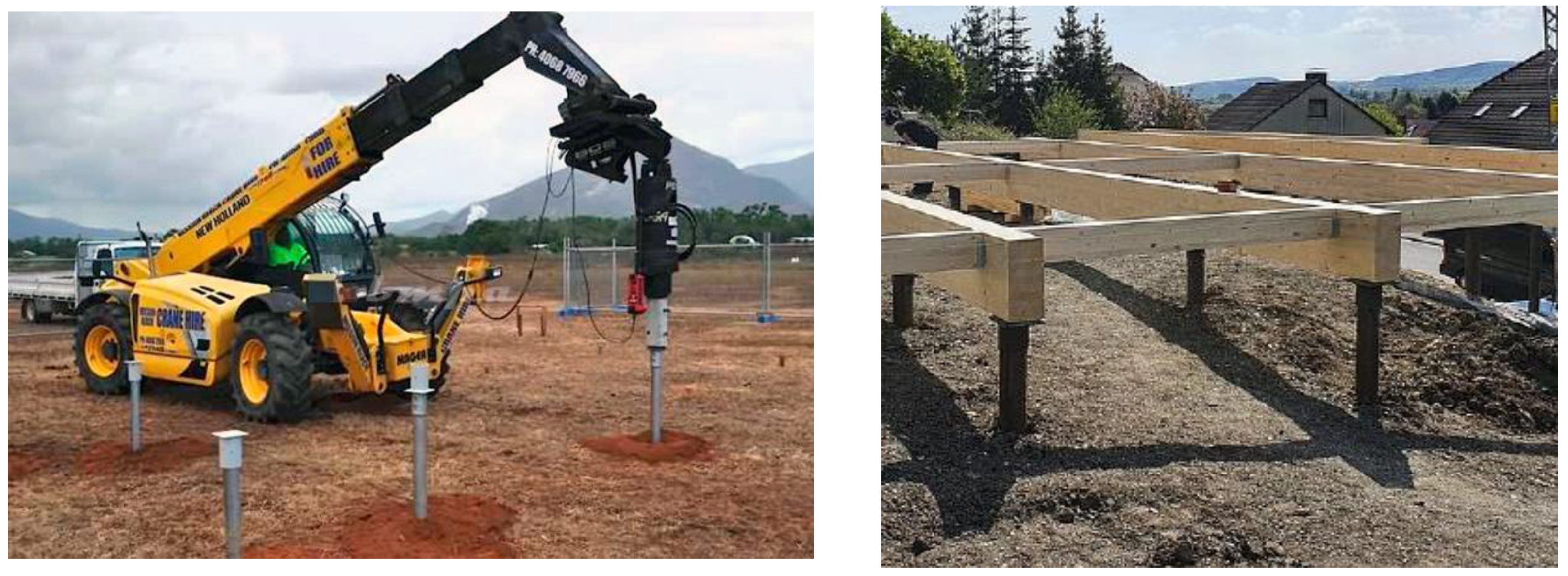
  51. Mohajerani, A.; Bosnjak, D.; Bromwich, D. Analysis and design methods of screw piles: A review. Soils Found. 2016, 56, 115–128. [Google Scholar] [CrossRef] [Green Version]
  52. Nekooie, M.A.; Tofighi, M. Resilient and Sustainable Modular System for Temporary Sheltering in Emergency Condition. Vitr. Int. J. Archit. Technol. Sustain. 2020, 5, 11946. [Google Scholar] [CrossRef]
  53. Cascone, S.M.; Caruso, C.; Russo, G.; Tomasello, N. Costruire in Emergenza: Progetto di un Rifugio Efficiente, Sostenibile e di Rapida Installazione, Colloqui.At.e 2018; Edicom Edizioni: Monfalcone, Italy, 2018. [Google Scholar]
  54. Asfour, O.S. Learning from the past: Temporary housing criteria in conflict areas with reference to thermal comfort. Int. J. Disaster Risk Reduct. 2019, 38, 101206. [Google Scholar] [CrossRef]
  55. Faragallah, R.N. Fundamentals of temporary dwelling solutions: A proposed sustainable model for design and construction. Ain Shams Eng. J. 2021, 12, 3305–3316. [Google Scholar] [CrossRef]
  56. Yu, H.; Bai, G. Research on Modularization and Sustainable Design of Temporary Housing. Art Des. Rev. 2018, 6, 125–132. [Google Scholar] [CrossRef] [Green Version]
  57. De Bernardini, P.; Marchionni, C.; Capannolo, L. Mob:om: A multifunctional prefabricated and flexible module. Int. J. Comput. Methods Exp. Meas. 2017, 5, 522–531. [Google Scholar] [CrossRef]
  58. Fang, D.; Pan, S.; Li, Z.; Yuan, T.; Jiang, B.; Gan, D.; Sheng, B.; Han, J.; Wang, T.; Liu, Z. Large-scale public venues as medical emergency sites in disasters: Lessons from COVID-19 and the use of Fangcang shelter hospitals in Wuhan, China. BMJ Glob. Health 2020, 5, e002815. [Google Scholar] [CrossRef] [PubMed]
  59. Pasqualis, M.B. Temporary houses for post-disaster and social emergency. Plan J. 2016, 1, 185–211. [Google Scholar]
  60. Ma, Y.; Xu, W.; Qin, L.; Zhao, X. Site Selection Models in Natural Disaster Shelters: A Review. Sustainability 2019, 11, 399. [Google Scholar] [CrossRef] [Green Version]
  61. Baiardi, L.; Puglisi, V. MoNGUE project for the sustainable development of Mozambique. TECHNE J. Technol. Archit. Environ. 2018, 15, 175–183. [Google Scholar] [CrossRef]
  62. Abulnour, A.H. The post-disaster temporary dwelling: Fundamentals of provision, design and construction. HBRC J. 2014, 10, 10–24. [Google Scholar] [CrossRef] [Green Version]
  63. Cornaro, C.; Sapori, D.; Bucci, F.; Pierro, M.; Corrado, G. Thermal performance analysis of an emergency shelter using dynamic building simulation. Energy Build. 2015, 88, 122–134. [Google Scholar] [CrossRef]
  64. Şener, S.M.; Altun, M.C. Design of a post disaster temporary shelter unit. J. Fac. Archit. 2019, 6, 58–72. [Google Scholar]
  65. Bologna, R. Dimensione Operativa Della Temporaneità Abitativa Post-Disastro e Strumenti di Controllo Tecnico; Firenze University Press: Mansfield Park, Austrilia, 2020; ISSN 2239-0243. [Google Scholar] [CrossRef]
  66. Ribera, F.; Del Regno, R.; Cucco, P. New frontiers of temporary buildings. Passive housing modules. Int. J. Archit. Art Des. 2018, 4, 159–168. [Google Scholar] [CrossRef]
  67. Biolcati Rinaldi, M.; Venturi, L. Architettura Sanitaria di Emergenza. In Strutture Permanenti Realizzate con Tecnologie Appropriate; Clueb: Bologna, Italy, 2011. [Google Scholar]
  68. Costanzo, M. (Ed.) Architetture di Pace, Ospedali di Guerra; Gruppo Mancosu Editore: Roma, Italy, 2008. [Google Scholar]
  69. Pataleo, R. Attenti All’uomo Bianco; Eleuthéra editore: Milano, Italy, 2010. [Google Scholar]
  70. Staib, G.; Rosenthal, M.; Dörrhöfer, A. Atlante Della Progettazione Modulare, Progetto—Costruzione—Nuove Tecnologie; Utet Scienze Tecniche: Torino, Italy, 2010. [Google Scholar]
  71. Capolongo, S. Edilizia Ospedaliera, Approcci Metodici e Progettuali; Hoepli: Milano, Italy, 2006. [Google Scholar]
  72. GICHD. A Guide to Developing National Mine Action Standards; GICHD: Geneva, Switzerland, 2016; ISBN 978-2-940369-58-4. [Google Scholar]
  73. ACCA. Termus: Energy Certification and Calculating Energy Performance. Available online: https://www.acca.it/software-certificazione-energetica (accessed on 28 April 2022).
  74. Cascone, S.M.; Caporlingua, M.; Russo, G.; Tomasello, N. La “prefabbricazione per l’emergenza”: Excursus storico dalla nascita alle moderne applicazioni. In Proceedings of the 3° Convegno Internazionale “Storia dell’Ingegneria”, Napoli, Italy, 23–24 April 2018. [Google Scholar]
Figure 1. Modules for Temporary School Building intended use—Elementary School Circolo Rodari, Muspino di Sassa, L’Aquila.
Sustainability 14 08010 g001
Figure 2. MAP in the earthquake in Emilia Romagna Region, 2012.
Sustainability 14 08010 g002
Figure 3. Examples of containers.
Sustainability 14 08010 g003
Figure 4. Mini-excavator and mini-shovel equipped with a hydraulic drill for the installation of foundations on poles by screwing.
Sustainability 14 08010 g004
Figure 5. Floor panels and wall panels.
Sustainability 14 08010 g005
Figure 6. Environmental units.
Sustainability 14 08010 g006
Figure 7. Possible aggregation models.
Sustainability 14 08010 g007
Figure 8. Installation diagram of the panels.
Sustainability 14 08010 g008
Figure 9. Design solution 1 compact form.
Sustainability 14 08010 g009
Figure 10. Design solution 1 articulated form.
Sustainability 14 08010 g010
Figure 11. Design solution 2 compact form.
Sustainability 14 08010 g011
Figure 12. Design solution 2 articulated form.
Sustainability 14 08010 g012
Figure 13. Design solution 3 compact form.
Sustainability 14 08010 g013
Figure 14. Design solution 3 articulated form.
Sustainability 14 08010 g014
Figure 15. Design solution 4 compact form.
Sustainability 14 08010 g015
Figure 16. Design solution 4 articulated form.
Sustainability 14 08010 g016
Figure 17. Detail of the nodes of the vertical and horizontal lower closure and the vertical and horizontal upper closure.
Sustainability 14 08010 g017
Figure 18. Multifunctional module for ticket office intended use.
Sustainability 14 08010 g018
Figure 19. Abacus of the wall of the multifunctional module.
Sustainability 14 08010 g019
Figure 20. Details of technologies adopted for closure.
Sustainability 14 08010 g020
Figure 21. Module A obtained by the combination on the long side of 2 containers TOP 20′.
Sustainability 14 08010 g021aSustainability 14 08010 g021b
Figure 22. Module B obtained by the combination of 4 containers TOP 20′.
Sustainability 14 08010 g022
Figure 23. Module C obtained by the combination of 8 containers TOP 20′.
Sustainability 14 08010 g023
Figure 24. Module A modified in height, elevation and 3D.
Sustainability 14 08010 g024
Figure 25. Dimensional relationships between modules A, B, and C.
Sustainability 14 08010 g025
Figure 26. Structural elements of the module.
Sustainability 14 08010 g026
Figure 27. Construction details of the locking package.
Sustainability 14 08010 g027
Figure 28. Spatial configurations of possible clinics with type A module.
Sustainability 14 08010 g028
Figure 29. Example of acceptance in the green area with type A module.
Sustainability 14 08010 g029
Figure 30. Example of acceptance in the green area with type C module.
Sustainability 14 08010 g030
Figure 31. Floor plan of health care solution 1.
Sustainability 14 08010 g031
Figure 32. Views of health care solution 1.
Sustainability 14 08010 g032
Figure 33. Floor plan of health care solution 2.
Sustainability 14 08010 g033
Figure 34. Views of health care solution 2.
Sustainability 14 08010 g034
Figure 35. Floor plan of health care solution 3.
Sustainability 14 08010 g035
Figure 36. Views of health care solution 3.
Sustainability 14 08010 g036
Table 1. Dimensions for different types of containers.
Type of ContainerLength
min in mm
Width
min in mm
Height
in mm
Container Box 20′–40′605824382591
Container High Cube12,19224382896
Container Open Top 20′–40′605824382591
Container Flat Rack 20′–40′605824382591
Table 2. Main dimension references for 20′ and 40′ open-top containers.
20′ Open-Top Container
MeasuresExternalInternalOpening SideOpening Roof
Length6058 mm5800 mm-5700 mm
Width2438 mm2310 mm2280 mm2150 mm
Height2591 mm2280 mm2070 mm-
Interior volume32.6 sqm
Max Load27,980 kg
40′ Open-Top Container
MeasuresExternalInternalOpening SideOpening Roof
Length12,192 mm12,020 mm-11,800 mm
Width2438 mm2320 mm2280 mm2150 mm
Height2591 mm2380 mm2190 mm-
Interior volume66.4 sqm
Max Load26,680 kg
Table 3. Characteristics of the multifunctional module.
Gross Volume1015.36 mc
Gross surface dispersant791.92 sqm
Aspect ratio S/V0.78 1/m
Dispersant gross area of the glazing68.49 sqm
Whole heat capacity16,847.13 kJ/K
Table 4. Electricity demand for the multifunctional module for cities taken into account.
PADUAROME BARINAPLES
Electricity demand for artificial lighting (kWh/year)2111209420902089
Electricity demand for heating (kWh/year)12,800901775456563
Electricity demand for cooling (kWh/year)2505365436314265
Electricity demand for domestic hot water (kWh/year)134756764
Euro/year2810237521352080
Table 5. Quantification of renewable energy produced by the photovoltaic and solar thermal energy plant and necessary waste energy required to show that the module is zero energy building.
ROWITEMPADUAROMEBARINAPLES
1% of coverage of the annual solar thermal plant covering demand for ACS68.183.6688.1489.60
2% of coverage of the annual demand of the photovoltaic system75.6689.9593.1394.30
3Global primary energy demand (kWh/sqm year)256166.83143.22127.43
4Renewable energy (kWh/sqm year)164.83126.10114.58105.24
5Global energy performance
(kWh/sqm year)
91.1740.7328.6322.19
6Energy Class D.M. 26/6/15A4A4A4A4
Table 6. Measurements of modules A, B, and C.
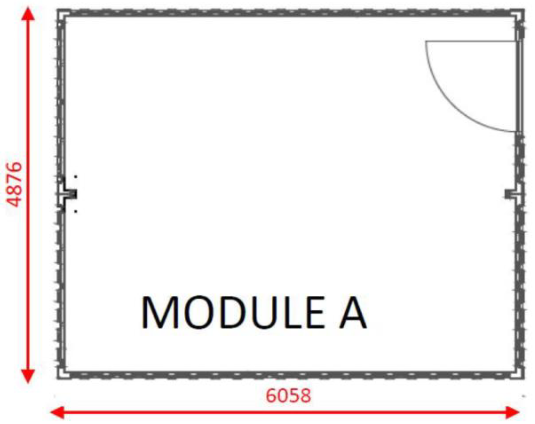
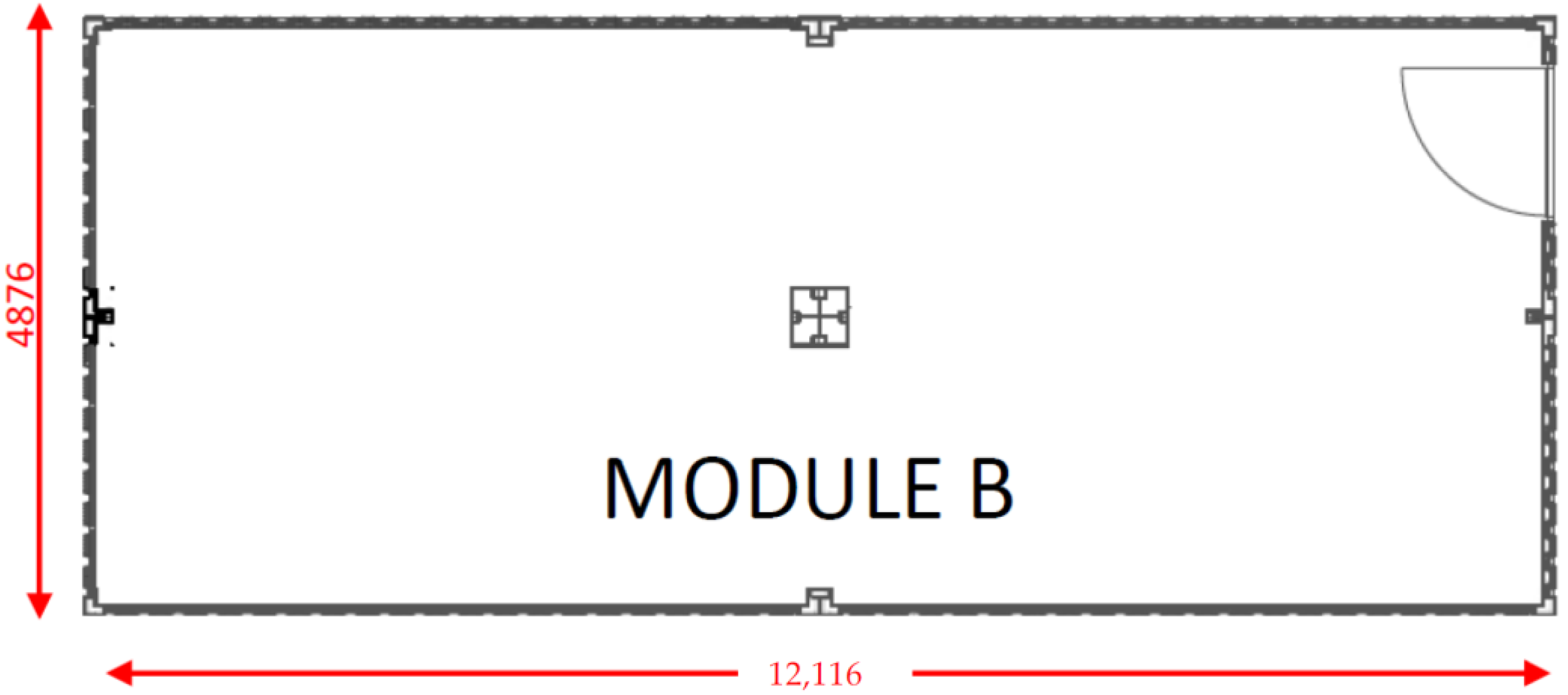
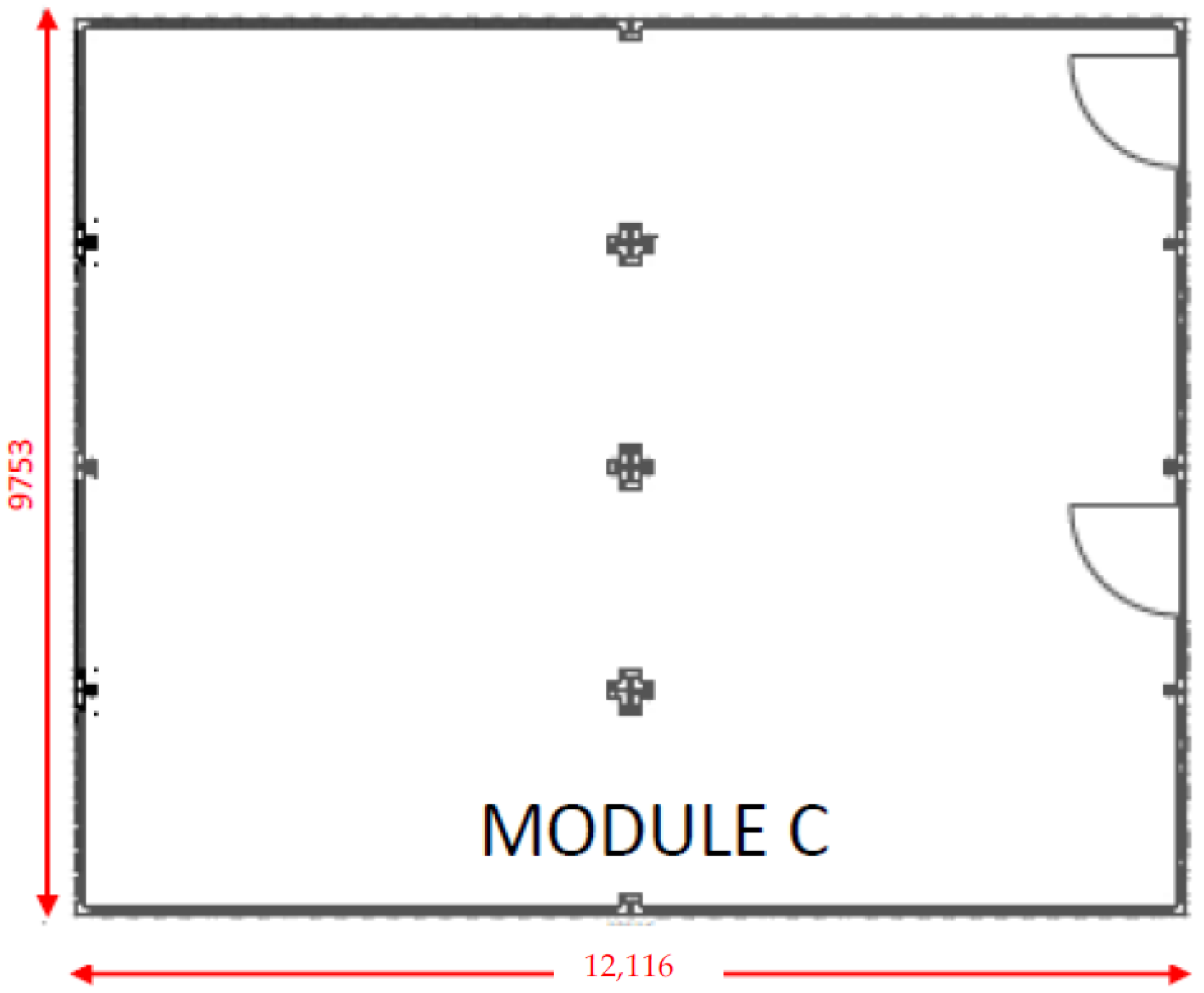
Modules Sizes A, B, and C
MeasuresModule A Module BModule C
Length6058 mm12,166 mm12,166 mm
Breadth4876 mm 4876 mm 9753 mm
Total height3748 mm 3748 mm 3748 mm
Lower structure height2591 mm 2591 mm 2591 mm
Table 7. Photovoltaic solar panels needed to module A to have an energy class A++.
StateCityMin. N° PanelsMin. N° Extra Panels
SomaliaBosaso75
SomaliaHargheisa84
SomaliaMogadiscio75
SomaliaBaydhabo75
MozambicoPemba75
MozambicoQuelimane66
MozambicoBeira66
EgittoEl Cairo84
AfghanistanMazar-i-Sharif102
AfghanistanBamyan102
AfghanistanKabul102
AfghanistanKandahar100
AngolaM’banza-Kongo66
AngolaLuanda66
AngolaHuambo84
Bosnia ErzegovinaNeum103
Bosnia ErzegovinaSarajevo102
KuwaitAl-Kuwait111
CambogiaPhom Penh75
IraqSulaymaniyya93
IraqRutbah93
IraqMossul120
IraqBaghdad120
IranRasht93
IranTabriz102
IranAhvaz111
Table 8. Photovoltaic solar panels needed to module B to have an energy class A++.
StateCityMin. N° PanelsMin. N° Extra Panels
SomaliaBosaso1513
SomaliaHargheisa1612
SomaliaMogadiscio1414
SomaliaBaydhabo1315
MozambicoPemba1214
MozambicoQuelimane1315
MozambicoBeira1216
EgittoEl Cairo1711
AfghanistanMazar-i-Sharif208
AfghanistanBamyan217
AfghanistanKabul217
AfghanistanKandahar253
AngolaM’banza-Kongo1315
AngolaLuanda1216
AngolaHuambo1612
Bosnia ErzegovinaNeum1810
Bosnia ErzegovinaSarajevo208
KuwaitAl-Kuwait226
CambogiaPhom Penh1513
IraqSulaymaniyya199
IraqRutbah199
IraqMossul244
IraqBaghdad262
IranRasht1810
IranTabriz217
IranAhvaz235
Table 9. Photovoltaic solar panels needed to module C to have an energy class A++.
StateCityMin. N° PanelsMin. N° Extra Panels
SomaliaBosaso4024
SomaliaHargheisa4123
SomaliaMogadiscio3824
SomaliaBaydhabo4015
MozambicoPemba3826
MozambicoQuelimane3628
MozambicoBeira3331
EgittoEl Cairo4321
AfghanistanMazar-i-Sharif5014
AfghanistanBamyan5014
AfghanistanKabul5113
AfghanistanKandahar604
AngolaM’banza-Kongo3628
AngolaLuanda3430
AngolaHuambo4123
Bosnia ErzegovinaNeum4519
Bosnia ErzegovinaSarajevo4915
KuwaitAl-Kuwait5311
CambogiaPhom Penh4024
IraqSulaymaniyya4717
IraqRutbah4717
IraqMossul586
IraqBaghdad622
IranRasht4519
IranTabriz5212
IranAhvaz559
Publisher’s Note: MDPI stays neutral with regard to jurisdictional claims in published maps and institutional affiliations.

