Abstract
The connection of electric vehicles to the power grid has a significant impact on the structure and stability of the power grid. To evaluate the performance index of a power grid, this paper introduces a collaborative evolution model of a power grid containing electric vehicles based on a complex network. The location of the electric vehicle network node is obtained by combining the evolution mode of the complex network and the restrictive conditions of the electric vehicle access network. Due to the dual attributes of electric vehicles, such as load and battery, electric vehicle access points will be used as special nodes in the network to calculate their effect on the power grid. In this paper, the Monte Carlo method is used to evaluate the effect of electric vehicle nodes on the whole network in the case of each probability failure in the power grid. The proposed method is numerically illustrated in the test case of the rbt-bus-f4 feeder system.
1. Introduction
According to the pattern of world energy development [1], electric vehicles (EVs) and other novel energy vehicles with environmentally protective low-carbon footprint, low cost, and sustainable development [2] will be vigorously developed. However, as large-scale electric vehicles are connected to the power grid, they are bound to produce a huge impact on the physical structural and operational characteristics of the power grid [3,4]. First, when electric vehicles are connected to the power grid, the structure of the distribution network is changed [5], and the evolution law of the power system is affected [6,7]. Second, the dual properties of EV loads and batteries change the one-way radiation of distribution networks [8]. Therefore, the connection of a large number of electric vehicles to the power grid will bring significant fluctuations to the stability of the power system [9,10,11]. In view of the stability requirements of power systems and the operational characteristics of electric vehicles, a study on the reliability of distribution networks with large-scale electric vehicle access is urgently needed.
At present, many research teams at home and abroad have studied the influence of electric vehicle integration on power grid reliability. The literature [12,13,14] considers the reliability of distribution networks based on the energy interaction between electric vehicles and the power grid from the perspectives of safety, efficiency, and performance of EV integration, but it fails to judge the impact of electric vehicle nodes accessing the power system structure. Literature [15,16] calculates the basic characteristic indices of the network according to the power system topology, judging whether the structure of the power system is reasonable according to the indices, but fails to consider the network characteristics of the power grid itself. Existing studies in literature [17,18,19] use a fully distributed framework to solve the charge scheduling problem of large-scale electric vehicles. The scheduling must not only meet the individual needs of electric vehicles but must also optimize the overall total energy cost. Under the condition of limited distribution network capacity, a global optimal energy supply and demand algorithm is proposed. This algorithm is also well-suited to applications in other complex networks. The literature [20,21] points out that the current distribution network, especially the distribution network in developed areas, has the characteristics of a complex network, and the scale of EVs is gradually increasing, so it has obvious advantages for in evaluating the stability performance of electric vehicles on the power grid, but the coevolution of electric vehicles and the power grid is not combined from the perspective of a complex network structure. Reference [22] studies the chain failure of a power grid by random attack or deliberate attack on nodes or edges of a power grid and obtains the vulnerability analysis of important nodes in a power grid facing failure. In reference [23], many elements of power plant and substation construction, including site selection, constant volume, and access mode of the power grid, are considered for the process of power grid growth and evolution, and a small-world power grid generation and evolution model is constructed. The results show that a complex network is reasonable for studying the evolution characteristics of a distribution network. Reference [24] proposes a complex network to structure the power grid around distributed power supply. Based on the calculation of the basic characteristic indices of the node degree, mediums, and aggregation coefficients of the network, the weighted statistical indices of the complex network of the power system with distributed generation (DG) are obtained. The changes in power system network power flow transmission efficiency before and after joining DG are analyzed to provide a basis for future grid planning and construction. On this basis, reference [25] quantitatively analyzes the vulnerability of the power grid using the network connectivity, transmission efficiency decline percentage, maximum transmission capacity, and other indicators. It shows that the topology of the power system has an important impact on the distribution of power outage data through the fault model.
However, since the distribution network gradually presents the characteristics of a complex network [26], it is a typical scale-free network [27]. In the literature above, the load analysis of electric vehicles and the stability analysis of the power grid are simply carried out, and the electric vehicles accessing the power grid, the structure of the power grid as nodes, and the role of nodes in the power grid are not explored from the perspective of the power grid system. Based on the complex network evaluation method of the subjective weighting method [28], this paper studies the stability of a complex network in which large-scale electric vehicles are connected to the distribution network and coevolve with the power system [29,30]. By calculating the structural characteristics of the power network, the regional evolution law of the power system is determined, and the reasonable access position of electric vehicles is determined. Furthermore, the Monte Carlo method was constructed to simulate the reliability index of electric vehicles after they were connected to the distribution network [31], and the evaluation basis for the stability of the distribution network after the coevolution of the distribution network and electric vehicles was obtained. Simulation results show that the proposed method can be used to effectively assess the stability of the power system after large-scale electric vehicles are connected. The stability of the power grid has been improved by 7%.
2. Regional Evolution Model of a Power Grid Based on a Complex Network
EV access is connected to the distribution network in the form of loads. This section refers to the complex network characteristics of the power grid and integrates the structure of the power grid to obtain the network model of the coevolution of EVs and the power grid through the evolutionary modeling of the power network.
Evolution of Power Systems
A power system is a typical scale-free network [27], and its evolution rules should first follow the two basic principles of a complex network:
- (1)
- Growth: The scale of the network is constantly increasing. If there is a connected network containing M0 nodes, each new node will be connected to the existing M nodes, and m ≤ M0.
- (2)
- Priority connection: the probability of a new node connecting to an existing node i is, and the connection probability of node i is related to the degree of that node, ki:where superscript Σjkj is the sum of node degrees in a network, assuming that the network evolves to step t. The network produces a network with N = t + m0 nodes and mt + M0 edges. When t = 0, m0 links between M0 nodes. The relationship between the continuous variable and node number is 0 < M0 ≤ 1/2 (m0(m0 − 1)).
In the power system, the access of new nodes and the evolution of the network should not only consider the evolution direction of the optimal structure but also need to consider other factors including the distance and node capacity grade. The distance factor takes into account the cost of the line length, while the node grade factor takes into account the device capacity and other factors. Therefore, a “local characteristic” should be added to the evolution of grid nodes.
- (3)
- Local world: Select M nodes (N > M) from the network of N nodes as the local world of newly added nodes.
According to the above prerequisites, the following power system evolution model is established:
- Step 1: The components and connection modes in the network are calibrated, and the substation, transformer, and EV charging piles are specified as nodes. If there is a physical connection between nodes, it is marked as 1, and if there is no connection, it is marked as 0. The topology matrix, X, without electric vehicles is established. Suppose there are N nodes in the grid.
- Step 2: Set M as the size of the local area network (N > M), and randomly select a submatrix X′ with size M from the topology matrix.
- Step 3: Given probability P, the newly added node is connected to the nodes in the local world with probability P, and the nodes that meet the characteristics of the scale-free network are preferentially connected. Its probability for priority connection is:
- Step 4: Reconstruct the network for the newly added node.
3. Distribution Network Stability Evaluation Model Based on the Coevolution of Vehicle Networks
In the evaluation of system reliability, the generation of a system fault mode analysis table is an important step in evaluating its indicators. The fault mode analysis table can count the faults of feeders, circuit breakers, transformers, and other components as well as determine fault time and influence range that form the dataset needed to calculate the reliability.
3.1. Fault Types
Every accessory in the distribution network has a probability of failure, and different components have different positions in the distribution network and play different roles. Therefore, the distribution network failure is divided into three categories:
- (1)
- Distribution wire failure: The distribution wire is a link connecting two nodes. Each distribution wire connecting two nodes has a probability of failure. The failure of links at different locations will affect different areas.
- (2)
- Circuit breaker failure: The circuit breaker isolates the power grid in a section of the region, protecting the regional power grid as a whole. The position of the circuit breaker in the power grid is relatively fixed, and the affected region is fixed.
- (3)
- Transformer failure: the transformer is located at the power grid transmission terminal, and power passes through the transformer power supply to the user. The failure of the transformer will affect the power consumption of the connected users, and the affected area is constant.
3.2. Component Fault Sampling
The state duration of components in a power system is generally considered to be a random variable satisfying an exponential distribution, and the sampling formula can be expressed as:
In the formula, TTF is the normal operation time before component failure (h), TTR is the component failure time, namely, the component repair time (h), λ is the component failure rate (number of failures/year), u is the component repair rate (number of repairs/year), and R1 and R2 are uniformly distributed random numbers between [0, 1].
3.3. User Load Model
In reference [32], a load modeling method was proposed to obtain a time-varying load model:
According to Equation (4), the daily load curve (24 h) is generated according to the daily maximum load, and the weekly load curve (7 d) is generated according to the weekly maximum load curve, while the annual load curve (8760 h) is generated according to the annual maximum load curve. PLmax is the annual maximum load, Pweek(t) is the percentage of weekly peak load, Pday(t) is the percentage of daily load peak to weekly load peak, and Phour(t) is the he percentage of peak hourly load to peak daily load.
3.4. Charging and Discharging Power Sequence Model of Electric Vehicles
In this paper, the electric vehicle charging pile is regarded as a new node, and the state of the charging pile is the state of the node. The variables affecting the node state include the number of electric vehicles, the operation law of electric vehicles, and whether or not electric vehicles are participating in V2G. Taking 1000 electric vehicles connected to the power grid as an example, the number of electric vehicles entering the charging pile is shown in Figure 1 [16]:
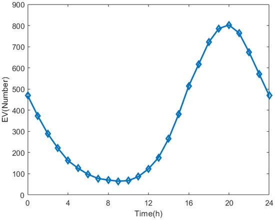
Figure 1.
Number of electric vehicles entering charging stations.
For a charging station, the charging load of EVs mainly depends on the number of EVs charging at the station. The number of EVs charging at the station can be fitted by a function. Analogous to the fitting curve of a fuel oil vehicle, the function is optimized to obtain the proportion distribution of the charging load of the charging station in each time period to the maximum charging load of the entire day:
In the event of a system failure, electric vehicles participating in V2G provide power to the grid to reduce load loss. According to reference [32], the time windows when the most users are willing to provide power to the grid is 10:00–15:00 and 22:00 to 4:00 in the morning of the next day. The supply of electricity from electric vehicles to the grid also depends on the number of electric vehicles at charging stations and the discharge power of electric vehicles. According to Equation (5), the corresponding discharge load can be obtained:
where Pdischarge is the discharge power of electric vehicles, Pcharge refers to the charging power of electric vehicles, and D(t) is the time gate function.
3.5. Fault Mode Analysis Method
In the final calculation of the indicator, the indicator data can be calculated after the fault is first determined. Therefore, the failure mode analysis table is established as follows: MF = [SF, EF, TF, NF, LF], where MF is the failure mode analysis table, SF is the failure type, EF is the failure component, TF is the failure time of the component, and TF is the repair time. NF is the number of affected users, and LF is the load loss after failure.
In the fault analysis table, the first step is to determine the fault type. In Section 3.1, it is proposed that there are three kinds of component faults in the distribution network, among which the transformer fault, which affects only the end node, does not affect other nodes in the network. Thus, the parameters in MF can be directly determined. When the circuit breaker fails, its position in the power grid is fixed, so its affected area is relatively fixed. When the circuit breaker fails, it can determine whether there is output of electric vehicles in the isolated island formed by the circuit breaker fault and then determine whether the isolated island has power failure, the number and duration of power failures, and other parameters. In the case of wire distribution failure, since every wire distribution in the power grid is equally likely to fail, the location of the fault is uncertain, and the affected area is also uncertain. Therefore, the traversal of the fault is carried out by establishing a topology matrix and by using forward search and back search [33]. The power grid after failure can be divided into two areas: the unaffected area L and the affected area I. It can be determined whether there are EV nodes in the affected area I, and it can be determined whether there is power failure in area I and the number and duration of power failure and other parameters.
To determine whether there is a power failure in the regional network containing electric vehicles, we can compare the discharging quantity of electric vehicles, QE, with the load, QL, at the time of power grid failure. When QE > QL, the network is not affected; when QE < QL, the network is still out of operation. The outage time is the difference between the component maintenance time and the electric vehicle power supply time. The load loss is equal to the load loss at the fault point minus the battery input of the electric vehicle.
3.6. Reliability Indicators Based on the Monte Carlo Method
For power grid reliability evaluation from the perspectives of system fault nodes and system global index, the literature [34] put forward the corresponding reliability index, an index through which the model number of statistical power, the power outage time, influence of the number of users, and load loss were calculated. Electric vehicle access will impact the above data.
The calculation method of the load index is as follows:
where λS (times/year) is the average failure rate of the system load point, λi (times/year) is the failure rate of component i, Ri (hour/year) is the fault repair time of component i, RS (hour/year) is the equivalent repair time of each failure of the system load point, and Us (hour/year) is the average annual power failure time of the load point.
The formula for calculating system index evaluation is as follows:
- System Average Interruption Frequency Index (SAIFI)
The system average power outage frequency index represents the number of continuous power outages experienced by each user in the system in a specified time.
- Customer Average Interruption Duration Index (CAIDI)
The average power outage duration refers to the average power outage duration experienced by each user affected by a power outage in the system within the specified time.
- System Average Interruption Duration Index (SAIDI)
The system average power outage duration represents the total power outage duration experienced by each user in the system within the specified time.
- Average Service Availability Index (ASAI)
Average power supply availability refers to the ratio of the total number of hours of uninterrupted power supply to the total number of hours of power supply required by the user within a specified period.
- Energy Not Supplied (ENS)
The indicator of total power shortage of the system refers to the total power supply shortage of the system in a specified time, and its expected value is abbreviated as EENS.
where λj is the load failure outage rate numbered j, Nj is the number of load users numbered j, and n is the total load. Uj is the average power outage duration of load users numbered j, Li indicates the power required by the user in the case of a fault, Ui indicates the power supply duration required by the user in the case of a fault, LEV_dis represents the discharge power of EV under the condition of failure, and UEV_dis represents the discharge time of power from electric vehicles during power grid failure.
3.7. Reliability Evaluation of the Power Grid Based on the Sequential Monte Carlo Method
In the reliability evaluation section of this paper, the load loss of electric vehicles during the V2G period, which is not included in the loss of the power system, is considered. The electric vehicles do not parameterize the V2G period, which is calculated into the loss of the power system. When the power grid fails, EVs participating in V2G discharge to the power grid alleviate the loss of the power system. In each failure period, EVs can only supply power to nodes containing EVs in the fault area. Due to the limited energy stored by EVs, the duration of EVs discharging to the power grid will change randomly. Figure 2 is the flow chart of distribution network reliability evaluation based on the sequential Monte Carlo algorithm after EV connections.
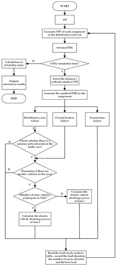
Figure 2.
Flow chart of grid evaluation with EVs.
- Step 1: Initialize the system clock and statistics and set t = 0.
- Step 2: The fault probability of each component is generated as a value between 0 and 1, the TTF of each component in the distribution network is generated using Equation (3), and t = t + min (TTF). Check whether t is less than the simulation time. If so, go to Step 3; otherwise, go to Step 9.
- Step 3: Select the smallest TTF component and generate the TTR of the component according to Equation (3).
- Step 4: Identify 1 power grid failure. Options are: 1 for cable failure, 2 for circuit breaker failure, and 3 for transformer failure. Go to Step 5 for option 1, Step 6 for Option 2, and Step 7 for Option 3.
- Step 5: Perform a traversal search for the distribution wire fault to find the point set I affected by the fault and determine whether the point set contains the main network node. If it does not, go to Step 6; if it does, go to Step 7.
- Step 6: Determine whether or not there are electric vehicles in the regional power grid and whether they participate in V2G. If there are no electric vehicles, go to Step 7; if there are no electric vehicles, go to Step 8.
- Step 7: Read the fault impact table, record the blackout duration, affected users, and lost loads, and then go to Step 2.
- Step 8: Calculate the electric vehicle discharge power, modify the fault mode analysis table, record the blackout duration, affected users and lost load value, and go to Step 2.
- Step 9: Calculate the reliability indicators of each node and the system.
- Step 10: Output the calculation results.
4. Power Grid Evolution and Evaluation
4.1. Evolution of the Power Grid
For power system builders, the greatest concern is whether the node location of electric vehicles connected to the power grid can optimize the structure of the power grid and the influence of electric vehicles connected to the power grid on the stability of the power grid. This paper uses the method of a complex network to carry out the evolution of the regional power grid, analyzes the difference between the evolution node and the random-access node on the reliability of the power grid, and analyzes the influence rule of electric vehicles before and after access to the power grid. From the perspective of system reliability, this study proposes relevant recommendations on the access of electric vehicles to the power grid. The following uses the RBT-BUS6-F4 feeder system as an example to carry out the evolution of the power system. Since RBT-BUS6-F4 has few nodes, the cost of the physical length of the wiring is not considered. In the process of evolution, only the probability of its preferential evolution needs to be considered. The partial degree and connection probability of this feeder system can be calculated according to Section 2, the nodal degree of distribution network is shown in Table 1 and the connection probability is shown in Figure 3.

Table 1.
RBT–BUS6-F4 Network evolution. Node degree list before evolution.
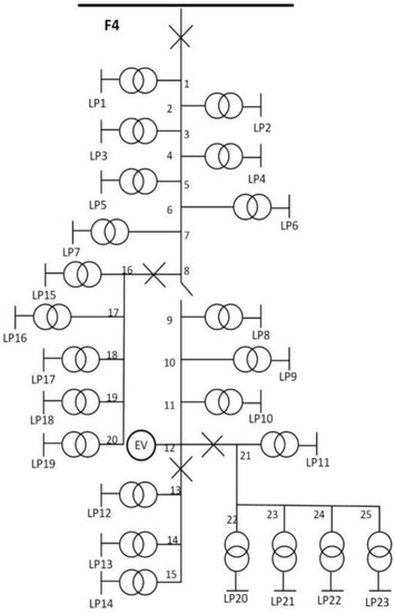
Figure 3.
RBT-BUS6-F4 Network evolution. After evolution, electric cars are connected to the grid.
Combined with the connection probability in the table, this paper selects node 12 as the EV contact in the network evolution and reconstructs the topology. To compare with stability after the evolution, this study randomly selects node 6 for EV contact and calculates the indicators of the two topological matrices.
4.2. Monte Carlo Grid Reliability Evaluation
First, the local power grid is analyzed through the classification of power grid faults. The fault type is shown in Figure 4.
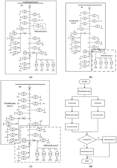
Figure 4.
Fault type and traversal search: (a) transformer failure chart, (b) circuit breaker failure chart, (c) distribution lines chart, and (d) back/forward searches flow chart.
- (1)
- Transformer failure
When the transformer fails, the affected area is the bottom user, and the access of electric vehicles will not supply power to the fault area of the transformer, so the fault analysis table can be directly generated to record the component failure and time. The failure rate is 0.015, and the repair time is 40 h. As shown in Figure 4a, when the transformer in the dotted box fails, loss load aggregate at J = {LP6}.
- (2)
- Circuit breaker failure
As shown in Figure 4b, when circuit breaker failure occurs; the figure also shows the positions of the circuit breaker failure occurring in the system. The system is divided into two regional networks including the point set of unaffected area L and affected area I, L = {F4, 1, 2, 3, 4, 5, 6, 7, 8, 9, 10, 11, 12, EV, 13, 14, 15, 16, 17, 18, 19, 20}. Because it contains main node F4, this area will not be affected by circuit breaker failure. Using the affected area aggregate I = {21, 22, 23, 24, 25}, the output of the electric car in this area is calculated, and area I determines whether the power outage occurs. If it is affected, the fault analysis table is generated, and the time and loss load of components affected by component failure is recorded. The failure rate is 0.006, and the repair time is 4 h.
- (3)
- Distribution lines
When the distribution wire fails, the probability of failure of all distribution wires is random, so the affected areas are different. In this case, the traversal search method described in literature [35] is used to identify the related nodes. As shown, the failure of feeder 12 between node 9 and node 10 in Figure 4c is used as an example to explain local network identification. The failure rate is 0.065, and the repair time is 5 h. The flow chart of traversal search is shown in Figure 4d.
First, seek the front node of the feeder, and the feeder is 9. Then, perform backword search.
9→8→7→6→5→4→3→2→1→F4.
Find the source node, F4, through push back search; finally, perform forward search.
F4→1→2→3→4→5→6→7→8→9→8→16→17→18→19→20.
Thus, the nodes contained in the corresponding local power grid L are.
L = {F4, 1, 2, 3, 4, 5, 6, 7, 8, 9, 16, 17, 18, 19, 20}.
The local network L contains the main network node F4, so the failure of feeder 12 will not affect the power outage of local network L. The end node, 10, is selected for the forward search so that the nodes contained in the local power grid are.
I = {10, 11, EV, 12, 13, 14, 15, 21, 22, 23, 24, 25}.
The load node set J contained in local power grid I is.
J = {LP9, LP10, LP11, LP12, LP13, LP19, LP20, LP21, LP22, LP23}.
As there are EV nodes in local power grid I, EVs will supply power to the network. In summary, the failure of feeder 12 will have an impact on load node set J. Because local area network I contains EV nodes, power failure can be avoided and load loss in the power grid may be reduced. In this paper, the simulation duration is set to 2 years. Through the above fault classification, the fault analysis table can be read as MF = [SF, EF, TF, NF, LF]. Finally, the reliability index can be calculated.
4.3. Impact of the Coevolution of EVs on the Reliability of Distribution Networks
To analyze the impact of grid evolution and node location of EV access on grid reliability, the following three working conditions are considered.
- Working Condition 1: there are no electric vehicles in the system,
- Working Condition 2: An EV node is connected to node 12 and participates in V2G,
- Working Condition 3: An EV node is connected to node 6 and participates in V2G,
- Working Condition 4: An EV node is connected to node 12 and does not participate in V2G.
Table 2 shows the stability index data in four cases calculated according to Section 3.6. Figure 5 is drawn according to Table 2, Figure 5 shows that operating Condition 2 has the lowest System Average Interruption Frequency Index (SAIFI), the shortest System Average Interruption Duration Index (SAIDI), the shortest Customer Average Interruption Duration Index (CAIDI), and the smallest Expect Energy Not Supplied (EENS). Among these four operating conditions, operating Condition 3 is worse than operating Condition 2 and slightly better than operating Condition 1. Condition 4 has the worst effect. The reason for the above results is that the structure of the local area network is adjusted to a better condition through network evolution. After evolution, node 12 is connected to the power grid as an EV node, and its power supply attribute can contribute to the power grid, playing a supporting role in the reliability of the power grid. Node 6, which is randomly connected, can also eliminate certain losses of power grid system output but cannot provide effective support for power grid reliability in terms of structure. In the case of working Condition 4, since the connected EV does not participate in V2G, the load is connected to the power grid and the load of the power grid is increased. Thus, its stability is reduced.
Table 2.
Comparison of stability indices under various working conditions.
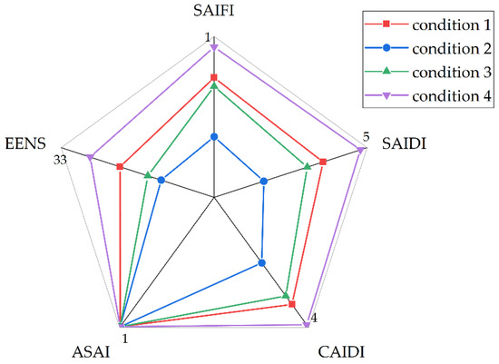
Figure 5.
Reliability indices under 4 different working conditions.
Based on the above analysis, after the reasonable evolution of the complex network, the power grid structure is optimized. When EVs participate in V2G, the SAIFI index of the power system increases by 2.57%, while the SAIDI index increases by 2.4% and the CAIDI index increases by 0.3%. The ASAI was virtually unchanged, and the EENS improved by 2.1%; the overall grid system reliability improved by 7%. Among the factors studied, SAIFI, SAIDI, CAIDI, EENS are associated with power outage duration, power frequency and loss load related. As electric cars are added to the grid, the indicators including ASAI, were promoted. Because the large base of electricity is power outage time and small, the index change is relatively very small, illustrating the overall power grid’s ability to meet user requirements. In contrast, when electric vehicles have load attributes and are connected to the power grid, this increases the burden of the power grid and reduces its reliability.
5. Conclusions
In this paper, a type of electric vehicle based on complex network coevolution with the grid method is proposed, and this determines the trend in electric power system evolution. After a traversal search for an electric car access table revised failure mode analysis, a data index is calculated using the Monte Carlo method to evaluate the effective access to power grid reliability. EV charging piles are connected to reasonable positions in the system through the evolution of the power grid and play a great role in supporting the reliability of the power system. Although this paper discusses the structural evolution and stability evaluation of the power grid, it does not study the effect of multifaceted fluctuations of electric vehicles on the power grid from a global perspective and the method of multipoint access. These will be the focus of future study.
Author Contributions
Conceptualization, Y.K.; Data curation, L.J. (Li Ji); Formal analysis, D.Z. and Y.K.; Investigation, D.Z., L.J. (Li Ji) and L.J. (Limin Jia); Methodology, D.Z. and L.J. (Li Ji); Project administration, D.Z., R.S. and L.J. (Limin Jia); Resources, R.S. and L.J. (Limin Jia); Software, Y.K.; Validation, L.J. (Limin Jia); Writing—original draft, D.Z.; Writing—review & editing, L.J. (Limin Jia) All authors have read and agreed to the published version of the manuscript.
Funding
This research received no external funding.
Institutional Review Board Statement
Not applicable.
Informed Consent Statement
Informed consent was obtained from all subjects involved in the study.
Data Availability Statement
The data that support the findings of this study are available from the corresponding author upon reasonable request.
Conflicts of Interest
The authors declare no conflict of interest.
References
- Wang, X.; Gong, J.; Zhang, H. Restricting factors and Countermeasures of New energy vehicle consumption in China—Thinking based on “double cycle” new development pattern. China Mark. 2021, 18, 23–24. [Google Scholar]
- Wang, Y.; Su, H.; Wang, W.; Zhu, Y. The Impact of Electric Vehicle Charging on Grid Reliability. In IOP Conference Series: Earth and Environmental Science; IOP Publishing: Bristol, UK, 2018; Volume 199, pp. 1–2. [Google Scholar]
- Wang, L. Orderly Charging Strategy for Electric Vehicles Based on Complex Network Theory; Nanjing University of Posts and Telecommunications: Nanjing, China, 2020. [Google Scholar]
- Chen, L. Study on the Influence of Extensive Access of Electric Vehicles on Power Grid and its Regulation Strategy; South China University of Technology: Guangzhou, China, 2018. [Google Scholar]
- Cao, J.; Ding, L.; Wang, G.; Bao, Z.; Han, Z. Dc Power Outage Model and Self-Organized Criticality Analysis Considering Network Evolution. Autom. Electr. Power Syst. 2009, 33, 1–6. [Google Scholar]
- Xie, Y.; Zhang, X.; Luo, J.; Xia, D.; Zhang, Y. Future power system evolution model with large-scale new energy access. Proc. CSEE 2018, 38, 421–425. [Google Scholar]
- Nie, C. Tandem Evolution of Power systems in China; China University of Mining and Technology: Beijing, China, 2017. [Google Scholar]
- Ai, S.; Lin, X.; Wan, Y.; Xiong, X. Research on active distribution network planning with multiple EV charging stations considering V2G mode. Proc. CSEE 2013, 33, 122–126. [Google Scholar]
- Bao, Y.; Jia, L.; Jiang, J.; Zhang, W. Research on mobile Energy storage auxiliary frequency Control strategy for electric vehicles. Trans. China Electrotech. Soc. 2015, 30, 115–126. [Google Scholar]
- Cao, Y. Impact of Large-Scale Electric Vehicles on Power Grid; North China Electric Power University: Beijing, China, 2015. [Google Scholar]
- Zhang, Q.; Tang, F.; Liu, D.; Zhou, S.; Guan, B.; Yang, J. Static Voltage Stability Evaluation scheme for Electric Power System Con-sidering Charging and Load Fluctuation Limit of Electric Vehicle. Power Syst. Technol. 2017, 41, 1888–1895. [Google Scholar]
- Zhao, X.; Wang, S.; Wu, X.; Liu, J. Coordinated Control Strategy of microgrid with Distributed Power supply and electric Vehicle. Power Syst. Technol. 2016, 40, 3–4. [Google Scholar]
- Rolink, J.; Rehtanz, C. Large-Scale Modeling of Grid-Connected Electric Vehicles. IEEE Trans. Power Deliv. 2013, 28, 894–902. [Google Scholar] [CrossRef]
- Mwasilu, F.; Justo, J.J.; Kim, E.K.; Do, T.D.; Jung, J.W. Electric vehicles and smart grid interaction: A review on vehicle to grid and renewable energy sources integration. Renew. Sustain. Energy Rev. 2014, 34, 501–516. [Google Scholar] [CrossRef]
- Liu, B.; Li, Z.; Chen, X.; Huang, Y.; Liu, X. Recognition and vulnerability analysis of key nodes in power grid based on complex network cen-trality. IEEE Trans. Circuits Syst. II Express Briefs 2017, 65, 346–350. [Google Scholar] [CrossRef]
- Bai, H.; Miao, S.; Qian, T.; Zhang, P. Study on reliability evaluation of combined generation system for distribution network in-cluding electric vehicles. Trans. China Electrotech. Soc. 2015, 30, 128–136. [Google Scholar]
- Parise, F.; Grammatico, S.; Gentile, B.; Lygeros, J. Distributed convergence to Nash equilibria in network and average aggregative games. Automatica 2020, 117, 108959. [Google Scholar] [CrossRef]
- Carli, R.; Dotoli, M. A distributed control algorithm for waterfilling of networked control systems via consensus. IEEE Control Syst. Lett. 2017, 1, 334–339. [Google Scholar] [CrossRef]
- Carli, R.; Dotoli, M. A distributed control algorithm for optimal charging of electric vehicle fleets with congestion management. IFAC-Pap. 2018, 51, 373–378. [Google Scholar] [CrossRef]
- Ponce-Jara, M.; Ruiz, E.; Gil, R.; Sancristóbal, E.; Pérez-Molina, C.; Castro, M. Smart Grid: Assessment of the past and present in developed and developing countries. Energy Strat. Rev. 2017, 18, 38–52. [Google Scholar] [CrossRef]
- Guo, S.; Zhao, H.; Zhao, H. The most economical mode of power supply for remote and less developed areas in China: Power grid extension or micro-grid. Sustainability 2017, 9, 910. [Google Scholar] [CrossRef] [Green Version]
- Zhang, G.; Zhang, J.; Yang, J.; Wang, C.; Zhang, Y.; Duan, M. Vulnerability assessment of large power system based on directed weight graph and complex network theory. Electr. Power Autom. Equip. 2009, 29, 21–26. [Google Scholar]
- Zhou, D.; Hu, F.; Chen, J. Robustness analysis of power system based on complex network. Power Syst. Prot. Control 2021, 49, 72–79. [Google Scholar]
- Liu, S. Influence of distributed power grid connection on distribution network voltage. Electr. Switchg. 2022, 60, 4–6. [Google Scholar]
- Pagani, G.A.; Aiello, M. Power grid complex network evolutions for the smart grid. Phys. A Stat. Mech. Its Appl. 2014, 396, 248–266. [Google Scholar] [CrossRef] [Green Version]
- Tan, Y.; Zhang, J.; Li, X. Importance evaluation of power grid nodes based on complex network theory. Comput. Eng. 2019, 45, 287–292, 303. [Google Scholar]
- Barabasi, A.L.; Albert, R. Emergence of scaling in random networks. Science 1999, 286, 509–512. [Google Scholar] [CrossRef] [PubMed] [Green Version]
- Shao, T. Research on evaluation System based on complex Network topology. Microcomput. Its Appl. 2017, 36, 69–72. [Google Scholar]
- Akrami, A.; Doostizadeh, M.; Aminifar, F. Power system flexibility: An overview of emergence to evolution. J. Mod. Power Syst. Clean Energy 2019, 7, 987–1007. [Google Scholar] [CrossRef] [Green Version]
- Xu, J.; Lv, T.; Hou, X.; Deng, X.; Liu, F. A bibliometric analysis of power system planning research during 1971–2020. IEEE Trans. Power Syst. 2021, 40, 100–110. [Google Scholar] [CrossRef]
- Bao, Y.; Wang, Y.; Tang, J.; Guo, C.; Wang, X.; Shi, H. Application difference analysis of sequential Monte Carlo method in power system reliability assessment. Power Syst. Technol. 2014, 38, 4–5. [Google Scholar]
- Yunus, K.J. Plug-in Electric Vehicle Charging Impacts on Power Systems; Chalmers University of Technology: Gothenburg, Sweden, 2010. [Google Scholar]
- Shi, H. Reactive Power Optimization of Multi-Objective Voltage in Distribution Network with Distributed Power Supply; Guangdong University of Technology: Guangzhou, China, 2014. [Google Scholar]
- Zheng, X. Reliability Evaluation of Distribution Network Based on Monte Carlo Method; Huazhong University of Science and Technology: Wuhan, China, 2011. [Google Scholar]
- Chen, Y.; Wang, Q.; Zhao, C.; Wei, T. Power flow calculation method of radial distribution network based on improved forward and backward substitution method. J. Nanjing Norm. Univ. Eng. Technol. Ed. 2008, 1, 24–29. [Google Scholar]
Publisher’s Note: MDPI stays neutral with regard to jurisdictional claims in published maps and institutional affiliations. |
© 2022 by the authors. Licensee MDPI, Basel, Switzerland. This article is an open access article distributed under the terms and conditions of the Creative Commons Attribution (CC BY) license (https://creativecommons.org/licenses/by/4.0/).