Article

Generalized Method for Determining the Width of a Safe Maneuvering Area for Bulk Carriers at Waterway Bends

Faculty of Navigation, Maritime University of Szczecin, 70-500 Szczecin, Poland
*
Author to whom correspondence should be addressed.
Sustainability 2022, 14(11), 6706; https://doi.org/10.3390/su14116706
Submission received: 20 April 2022 / Revised: 24 May 2022 / Accepted: 27 May 2022 / Published: 30 May 2022
(This article belongs to the Special Issue Frontiers of Maritime Spatial Planning and Management)

Abstract

:
There are a number of empirical methods for determining the width of safe maneuvering areas for ships on waterways. These methods are relatively accurate for straight sections of waterways and less accurate for curves of the waterways. When designing waterways in detail or determining the conditions for their safe operation, more accurate methods (e.g., simulations) are used. However, such studies require relatively large expenditure involving the construction of simulation models of various vessels and water areas, and conducting a real-time simulation experiment with a sufficiently large number of maneuvers performed by highly qualified navigators (pilots, captains). This study deals with the problem of determining the width of safe maneuvering areas of ships on the bends of the waterway based on the results of simulation studies. A new empirical method was developed to determine the width of safe maneuvering areas of loaded bulk carriers passing through fairway bends under deteriorated hydro-meteorological conditions. The method was developed on the basis of a generalization of the results of many simulation experiments carried out at various stages of the Świnoujście–Szczecin fairway reconstruction and a determination of the safe operating conditions for ships passing through the fairway.

1. Introduction

Safe widths of maneuvering areas calculated for a given type of ship on specific waterways allow us to design waterways or determine the conditions for safe operation of ships on existing waterways. At the stage of detailed design of waterway systems, simulation methods are used [1,2,3,4]. The result of their application is an accurately determined safe maneuvering area for vessels in operation or planned for operation. The most important limitation of the use of simulation methods, especially at the initial stages of design, is the large amount of work required to prepare adequately reliable models and the cost and time consumption resulting from the required number of simulation trials.
In addition to simulation methods, there are a number of empirical, deterministic or probabilistic methods to determine the safe width of maneuvering areas on fairways [5]. They are widely used, particularly at the preliminary stage of waterway design. The most important methods include:
  • The World Association for Waterborne Transport Infrastructure—PIANC;
  • Recommendations for Maritime Works—ROM (Spanish);
  • Japanese;
  • Centrum Inżynierii Ruchu Morskiego—CIRM.
The best known and most widely used is the PIANC method, in which the width of the maneuvering area for one-way traffic is calculated as the sum of the maneuvering width (basic maneuvering lane), additional widths taking the influence of external conditions, etc. into account, and an additional reserve taking the bank effect (bank clearance) into account. At bends, this width is increased by two corrections to account for the drift angle and response time [6]. This method has been used, for example, in the initial site selection of an LNG terminal in India [7], the determination of an approach fairway parameters in the Chinese port of Panjin [8] or fairway parameters in Korean waters [9]. In the ROM method, the width of the maneuvering area is expressed as the sum of the base lane (nominal width) considering the ship’s width and drift angle, as well as bank suction or the rejection effect and an additional reserve width for taking boundary-related factors into account. For the bends, this method considers two additional widths, taking the drift angle and the speed of the ship’s response to the setting change into account [10]. Similar to the above two methods, in the Japanese method, the width of the maneuvering area is the sum of the basic width (basic maneuvering lane), which accounts for the angle of drift and the possibility of detecting the vessel’s deviation from the assumed route, and additional widths (bank clearance) allowing for the bank effect [11,12].
Accuracy studies of these methods in relation to real-time computer simulation (RTS) methods conducted for a bulk carrier on the Świnoujście–Szczecin fairway (67.4 km) (LOA = 200 m, B = 32.3 m, T = 11.0 m) and a cruise ship (LOA = 260 m, B = 33.0 m, T = 9.0 m), where LOA indicates length (length over all), B indicates the breadth and T indicates the draught of the vessel, showed that:
  • On straight sections of the fairway, statistically insignificant differences from the simulation method were shown by PIANC [6], CIRM [13] and the Spanish method [10];
  • At the bends of the fairway, statistically insignificant differences for both bulk carriers and cruise ships were shown only by the CIRM method.
It is believed that only the CIRM method accurately accounts for the positional accuracy of a ship in any fairway for complex navigation systems and should provide better accuracy than the other methods.
In the CIRM method, at waterway bends for one-way traffic, the width of the safe maneuvering area (Figure 1) at the assumed confidence level (1 − α) is determined according to the relationship:
d z ( 1 ) = d m z + 2 d n z ( 1 )   [ m ]
where by the maneuvering component of the safe maneuvering area width is:
d m z = d m + Δ d   [ m ]
where dz(1−α) is the safe width of the maneuvering area for the bend at the confidence level (1 − α), dmz is the maneuvering component of the width of the safe maneuvering area at the bend, dnz(1−α) is the navigational component of the width of the safe maneuvering area at the bend determined at the confidence level (1 − α), dm is the maneuvering component of the width of the safe maneuvering area on a straight section and ∆d is the widening of the ship’s lane at the bend.
The maneuvering component of the safe maneuvering area at the bend is the sum of the maneuvering component determined for a straight section dm and the additional lane widening ∆d. Lane widening at the bend in the CIRM method is taken into account in cases when the planned radius of the bend is r < 10*LOA (LOA—length over all) according to the Taylor relationship adopted in the Canadian method [6]:
Δ d = 3.4551 · Δ ψ · V 2 · LOA 2 · F r · k z · s   [ m ]
where Δψ is the angle of turn (course change) (°), V is the vessel speed (m/s), F is a coefficient taking the value of 1 for one-way traffic and 2 for two-way traffic, r is the bend radius (m), s is the minimum required visibility from the bridge of the vessel (≥2446 m) and kz is the ship’s maneuverability index (1—poor, 2—good, 3—very good).
The navigational component at the bend of the fairway for the selected positioning system is the directional error of the ship’s bow position determined at a given confidence level. This is the directional error perpendicular to the fairway axis, which is [13]:
d n z ( 1 α ) = p y D ( 1 ) = p y ( 1 ) 2 + ( m K R ( 1 ) D L D 57 , 3 ° ) 2   [ m ]
where p y D ( 1 α ) is the directional error of the ship’s bow position at the confidence level (1 − α) (m), p y ( 1 α ) is the directional error of determining the vessel’s position (observer position) at the confidence level (1 − α) (m), m K R D ( 1 α ) is the error in determining the ship’s course in a turn at the confidence level (1 − α) (°) and LD is the distance between the ship’s bow and the ship’s bridge (m).
A certain limitation of the CIRM method is the lane widening ∆d at fairway bends determined by the relatively unreliable Taylor equation, which does not take hydrometeorological conditions into account.
This study presents a newly developed method for determining the width of safe maneuvering areas at fairway bends for the ships with a block coefficient Cb ≈ 0.8. The generalized method was developed based on the results of several simulation studies of bulk carriers of different sizes (LOA = 200 m ÷ 300 m,) passing through seven bends of the Świnoujście—Szczecin fairway, with a turning radius r = 1135 m ÷ 3000 m.

2. Research Method

The research on ship traffic on the bends of the Świnoujście–Szczecin fairway was carried out with the use of a simulation method, at various stages of modernization of the fairway. These studies were carried out on 7 bends of the track, with parameters as shown in Table 1.
The study was conducted on Kongsberg’s FMBS Class A simulator by building simulation models of the respective study water areas (bends) and the following vessels:
  • Bulk carriers:
    • LOA = 300 m, B = 48.1 m, T = 13.5 m Cb = 0.81;
    • LOA = 280 m, B = 45.0 m, T = 13.5 m Cb = 0.82;
    • LOA = 270 m, B = 41.5 m, T = 13.0 m Cb = 0.82;
    • LOA = 260 m, B = 40.0 m, T = 12.8 m Cb = 0.82;
    • LOA = 200 m, B = 29.0 m, T = 11.0 m Cb = 0.83;
  • Tanker (LPG carrier ROM): LOA = 250 m, B = 38.3 m, T = 11.0 m Cb = 0.82.
Simulation experiments in a series of 12 passes of specified vessels at a speed of 6 ÷ 8 knots on the tested bends were performed by port pilots. The individual series were performed under identical hydrometeorological conditions. These were the least favorable hydrometeorological conditions for the particular bends in which the tested vessels may be allowed to operate on the Świnoujście—Szczecin fairway. The wind velocity was from 10 m/s to 12.5 m/s from the side or stern directions, and the current velocity from 0.8 knots to 1.0 knots in accordance with the direction of vessel traffic.
The results of the simulation tests were statistically processed by determining the lanes: maximum, average and at the confidence level (1 − α) = 0.95. Examples of the results of the simulation tests of the bulk carrier with LOA = 200 m on the Ińskie bend performed at a 0.7 knot current and winds of S 10 m/s and W 10 m/s (2 series—24 passes) are shown in Figure 2.
The lanes identified by the simulation method at the confidence level (1 − α) = 0.95 determined the safe maneuvering area of the test vessel passing through the given bend.
According to the results of the simulation studies of individual maneuvers, the safe widths of the maneuvering areas of the studied ships at the specified bends were determined. Based on these, the lane widenings of the surveyed ships at the respective turns were calculated:
d(0,95) = dz(0,95) – dm – 2dnz(0,95)
where ∆d(0,95) is the ship’s lane widening at the turn determined at the confidence level (1 − α) = 0.95, dz(0,95) is the safe width of the maneuvering area at the bend determined by the simulation method (at a confidence level of 0.95), dm is the maneuvering component of the width of the safe maneuvering area on a straight track and dnz(0,95) is the navigational component of the safe maneuvering area width determined at a confidence level (1 − α) of 0.95.
The width of the maneuvering component of the safe maneuvering area on a straight track is for loaded ships with a high block coefficient Cb (good maneuverability) without considering additional corrections [13]:
dm = 1.5B [m]
while the navigational component for the terrestrial (optical) positioning method is defined as the directional error of the position of the bow of a ship passing through a bend in the track [13]:
d n z ( 0 , 95 ) = ± ( 0.05 b ) 2 + ( 3 LOA 57.3 ) 2
The results of the simulation studies (safe maneuvering area widths) and the calculated lane widenings at navigational turns determined at a confidence level (1 − α) of 0.95 are shown in Table 2. The safe maneuvering area widths (dz) shown in the table for each turn and ship were determined on the basis of the corresponding simulation study results:
  • Turn 1 and 2:
    • o Lc = 260 m [15];
    • o Lc = 270 [16];
    • o Lc = 280 m and 300 m [17];
  • turn 3 and 4: Lc = 250 m [18];
  • turn 5, 6 and 7: Lc = 200 m [16].

3. Results

Thirteen results of the simulation studies (lane widening) of six loaded vessels (five bulk carriers, one LPG tanker) on seven different bends of the Świnoujście—Szczecin fairway were used to determine the functional dependence of lane widening (∆d) of loaded bulk carriers on the bends of the fairway (see Table 2).
Preliminary analysis of the lane widening of loaded bulk carriers (LOA = 200 m ÷ 300 m) at the examined bends of the Świnoujście–Szczecin fairway showed that this value is directly proportional to the length of the ships (LOA) and inversely proportional to the turn radius (r), while it depends very little on the turn angle (∆ψ).
According to regression analysis methods, the dependence of lane widening at a fairway bend on vessel length and turn radius was determined (Figure 3).
d = 512.5 (LOA/r)2 + 9.45
with the following regression statistics:
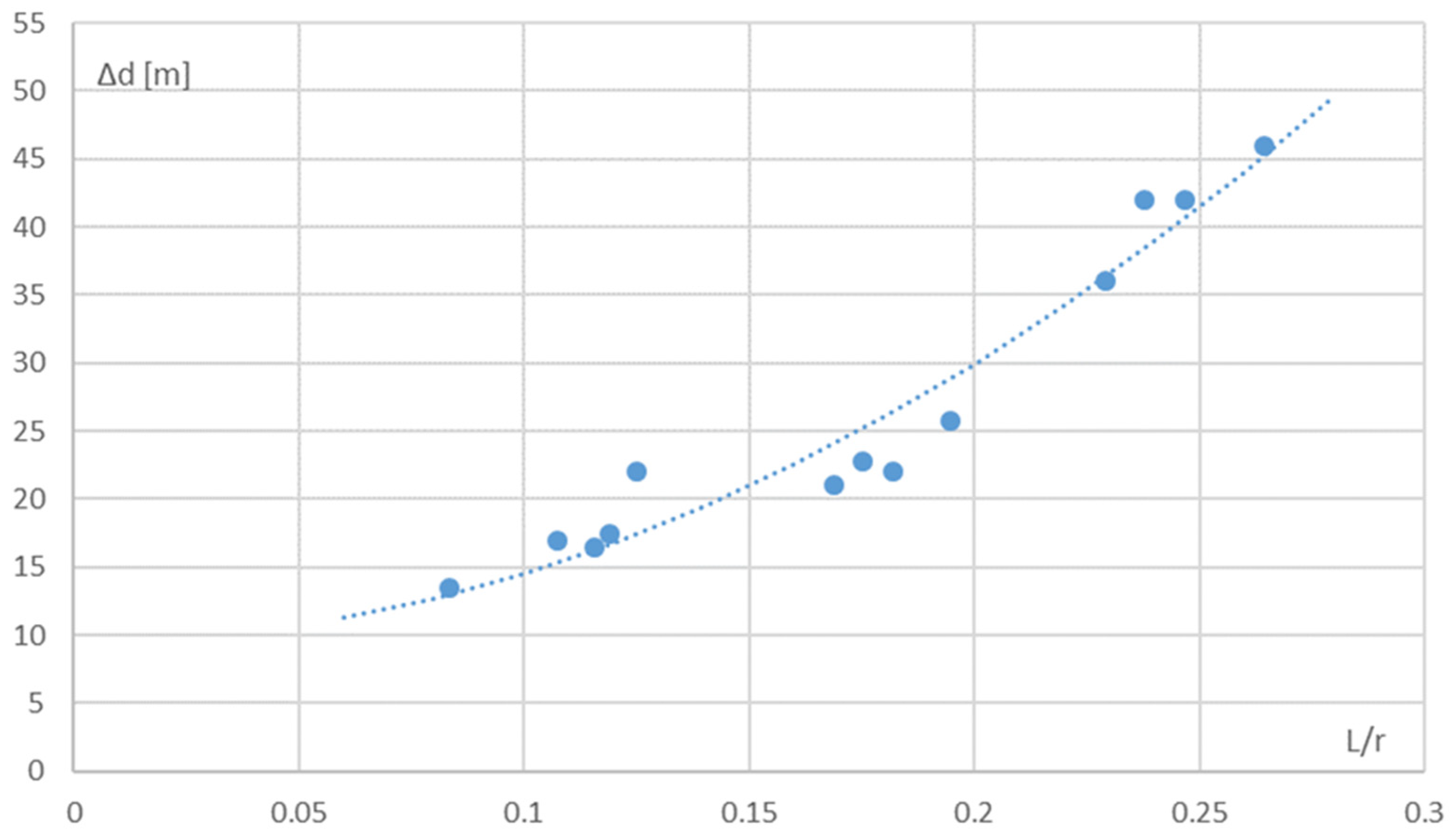
  • Coefficient of determination: R2 = 0.9435;
  • Standard deviation of the residual components of all observations: δ13 = 2.7533.
The residual components of each observation are shown in Table 3.
The high coefficient of determination (R2) indicates the good fit of the mathematical model to the results of the simulation study. None of the observations can be rejected because their residual components are less than two standard deviations of all observations.
Additionally, according to the regression analysis method, the linear dependence of lane widening on vessel length and turning radius was determined (Figure 4):
d = 155.25*LOA/r
The coefficient of determination of this relationship is R2 = 0.8783 and shows that it can be used in the preliminary design of waterways and the approximate determination of their safe operation conditions.
On the basis of the test results presented above, the maneuvering component of the width of safe the maneuvering areas of loaded bulk carriers with a LOA of 200 m ÷ 300 m (block coefficient Cb = 0.81 ÷ 0.83) passing the bends of the fairway with radius of r = 1100 m ÷ 3000 m was determined. Individual tests (ship maneuvers) were performed on bends with a radius of r/LOA ≈ 4 ÷ 12 at turning angles of ∆ψ = 13° ÷ 90° under poor hydrometeorological conditions (wind with a velocity of Vw = 10 m/s ÷ 12.5 m/s from the side or stern directions and a current with a speed of Vp ≤ 1.0 knots in the longitudinal direction from the stern).
For the adopted constraints, the maneuvering component of the safe maneuvering area width is:
dmz = 1.5B + 512.5 (LOA/r)2 + 9.45 [m]
The approximate width of a maneuvering area that can be used for preliminary design or preliminary determination of the conditions for the safe operation of vessels is:
dmz = 1.5B + 155.25 LOA/r [m]

4. Discussion

At the present stage, the presented method can be used to determine the width of the safe maneuvering area only for ships with a large block coefficient. To extend the scope of application, further work on the development of the method will concern the determination of the relationship between the values of the determined coefficients and the value of the block coefficient. This will allow the method to be applied to other types of ships, e.g., container ships or cruise ships with a different (smaller) block coefficient. The final stage of the method development will be its verification, which will be carried out by comparing the obtained results with the results of specially prepared simulations, which were not used during the method’s development.
The undoubted advantage of the presented method is the reduction of the work and time required for simulation methods. Building models of a body of water, a ship and external conditions from scratch, and then carrying out research and statistical processing of the results may take up to several weeks (depending on the complexity of the models and maneuvers). For the presented method, the results can be obtained within one day (several days maximum).
At the current stage of development, the method cannot fully replace simulation methods, but it can be used to optimize them, e.g., by reducing the number of required scenarios (thanks to the possibility of determining the worst-case scenario).

5. Conclusions

This study presents a newly developed method for determining the width of safe maneuvering areas of ships at fairway bends. The method was developed on the basis of the results of several simulation studies of bulk carriers of different sizes (LOA = 200 m ÷ 300 m) passing through 7 bends of the fairway Świnoujście—Szczecin. According to this method, the maneuvering component of the width of safe maneuvering areas for this type and size of ship is:
dmz = 1.5B + 155.25 LOA/r [m] or dmz = 1.5B + 512.5 (LOA/r)2 + 9.45
This relationship determines the maneuvering width component of safe maneuvering areas of loaded ships with a length of LOA = 200 m ÷ 300 m and block coefficient of Cb ≈ 0.8 passing through bends with a radius of r/LOA = 4 ÷ 12 under adverse hydro-meteorological conditions (wind speed up to 12.5 m/s, longitudinal current speed up to 1.0 knots).
By knowing the maneuvering component, it is possible to determine the width of the safe maneuvering area of loaded ships with a block coefficient of Cb ≈ 0.8 (bulk carriers, tankers) on turns using the known relationship [13].
dz(0,95) = dmz + 2dn(0,95) [m]
and, based on this, determine the minimum width of the available shipping basin [6]:
D = dz(0,95) + 2dr [m]
where dr is the width reserve, considering the edge-channel effect.
In conclusion, it can be stated that this method allows us to reduce the time and workload required for:
  • detailed designs of fairway bend parameters;
  • determining the conditions for the safe operation of vessels on existing waterways.

Author Contributions

Conceptualization, S.G.; methodology, S.G.; software, R.G. and M.P.; validation, S.G.; formal analysis, S.G., R.G. and M.P.; investigation, S.G., R.G. and M.P.; resources, R.G. and M.P.; data curation, R.G. and M.P.; writing—original draft preparation, S.G.; writing—review and editing, R.G. and M.P.; visualization, M.P.; supervision, S.G.; project administration, R.G. and M.P.; funding acquisition, R.G. and M.P. All authors have read and agreed to the published version of the manuscript.

Funding

This research received no external funding.

Institutional Review Board Statement

Not applicable.

Informed Consent Statement

Not applicable.

Data Availability Statement

Not applicable.

Conflicts of Interest

The authors declare no conflict of interest.

References

  1. Artyszuk, J.; Gralak, R.; Gucma, M.; Gucma, S.; Ślączka, W.; Zalewski, P. Optimization of waterway bend widths using computer simulation methods of ship movement. Sci. J. Marit. Univ. Szczec. 2016, 46, 115–121. [Google Scholar]
  2. Bian, X.; Yan, Q. Determining the Width of Bend Channel for Very Large Vessels Based on Simulation Trials. In Proceedings of the ICTIS 2013: Improving Multimodal Transportation Systems-Information, Safety, and Integration, Wuhan, China, 29 June–2 July 2013; pp. 2250–2256. [Google Scholar]
  3. Quy, N.M.; Vrijling, J.K.; Van Gelder, P.H.A.J.M. Risk-and simulation-based optimization of channel depths: Entrance channel of Cam Pha Coal Port. Simulation 2008, 84, 41–55. [Google Scholar] [CrossRef]
  4. Amendola, J.; Miura, L.S.; Costa, A.H.R.; Cozman, F.G.; Tannuri, E.A. Navigation in Restricted Channels Under Environmental Conditions: Fast-Time Simulation by Asynchronous Deep Reinforcement Learning. IEEE Access 2020, 8, 149199–149213. [Google Scholar] [CrossRef]
  5. Gucma, S.; Zalewski, P. Optimization of fairway design parameters: Systematic approach to manoeuvring safety. Int. J. Nav. Archit. Ocean Eng. 2020, 12, 129–145. [Google Scholar] [CrossRef]
  6. PIANC. Setting the Course, Harbour Approach Channels; Design Guidelines Report n° 121–2014; PIANC: Brussel, Belgium, 2014. [Google Scholar]
  7. Rushidh, M.D.; Suhuraa, S.; Reddya, L.R.; Dwarakisha, G.S. Planning of Marine Facilities for an LNG Terminal in India. In Proceedings of the GITA-2K15, SMVITM, Bantakal, India, 16–17 October 2015. [Google Scholar]
  8. Zhang, L. Discussion on the Method for Determining the Harbor Channel Design Width-Take the Proposed 250,000 ton Waterway of Panjin Harbor for Instance. Adv. Mater. Res. 2015, 1065, 480–485. [Google Scholar]
  9. Kang, W.S.; Park, Y.S. A Study on the Design of Coastal Fairway Width Based on a Risk Assessment Model in Korean Waterways. Appl. Sci. 2022, 12, 1535. [Google Scholar] [CrossRef]
  10. Puertos, D.E. ROM 3.1-99. Design of the Maritime Configuration of Ports, Approach Channels and Harbour Basins; Spanish National Ports and Harbours Authority: Madrid, Spain, 2007. [Google Scholar]
  11. Ohtsu, K.; Yoshimura, Y.; Hirano, M.; Takahashi, H.; Tsugane, M.; Ohtsu, K. Design standard for fairway in next generation. Proc. Korean Inst. Navig. Port Res. Conf. 2006, 2006.10a, 230–239. [Google Scholar]
  12. Ports and Harbours Bureau; Ministry of Land, Infrastructure; Transport and Tourism (MLIT); National Institute for Land and Infrastructure Management; MLIT; Port and Airport Research Institute. Technical Standards and Commentaries for Port and Harbour Facilities in Japan; The Overseas Coastal Area Development Institute of Japan: Tokyo, Japan, 2009. [Google Scholar]
  13. Gucma, S. Marine Traffic Engineering. Guidelines for Design of Waterways and Ports and Conditions of Their Safe Operation; Foundation for the Promotion of the Shipbuilding Industry and Maritime Economy: Gdańsk, Poland, 2007. [Google Scholar]
  14. Maritime University of Szczecin. Navigational Analysis of Modernization of the Świnoujście-Szczecin Waterway (Dredged to 12.5 m); Maritime University of Szczecin: Szczecin, Poland, 2014. [Google Scholar]
  15. Maritime University of Szczecin. Determination of Maximum Ships Which Can Safely Enter Commercial Port in Świnoujście Based on Simulation Studies; Maritime University of Szczecin: Szczecin, Poland, 2010. [Google Scholar]
  16. Maritime University of Szczecin. Optimal Determination of the Maximum Ships which Can Safely Enter the Commercial Port in Świnoujście Based on Simulation Studies; Maritime University of Szczecin: Szczecin, Poland, 2003. [Google Scholar]
  17. Maritime University of Szczecin. Navigational Analysis of the Reconstruction of the Northern Approach Track to Świnoujście from 0.0 km to 1.0 km and the Świnoujście–Szczecin Waterway from 0.0 km to 3.1 km; Maritime University of Szczecin: Szczecin, Poland, 2014. [Google Scholar]
  18. Maritime University of Szczecin. Detailed Guidelines for Designing the Target Solution of the Hydrotechnical Development of the Waterway Świnoujście–Szczecin km 0.0–16.5. Stage III; Maritime University of Szczecin: Szczecin, Poland, 2000. [Google Scholar]
Figure 1. Width of the safe maneuvering area at a waterway bend.
Sustainability 14 06706 g001
Figure 2. Bulk carrier lanes (LOA = 200 m) at Ińskie bend. Wind, 10 m/s S and W; current 0.7 knots (24 passes) [14].
Sustainability 14 06706 g002
Figure 3. Plot of the lane widening function for a bend.
Sustainability 14 06706 g003
Figure 4. Plot of the linear function of lane widening at a bend.
Sustainability 14 06706 g004
Table 1. Parameters of the tested bends of the Świnoujście—Szczecin fairway.
No.Name of the BendFairwayCourse Change (∆ψ)Radius (r)Distance between Shore Lines (b)
1Approach to Świnoujście 90°1.540 m280 m
2Port entrance0 km79°1135 m330 m
3Mielin7.6 km28°3000 m290 m
4Paprotno10.9 km19°2330 m310 m
5Ińskie51.9 km31°1680 m500 m
6Babina55 km23°1730 m330 m
7Święta59.4 km14°1600 m280 m
Table 2. Parameters of the tested bends of the Świnoujście—Szczecin fairway.
No.BendVessel Parameters
Lc = 200 mLc = 250 mLc = 260 mLc = 270 mLc = 280 mLc = 300 m
B = 29.0 mB = 38.3 mB = 40.0 mB = 41.5 mB = 45.0 mB = 48.1 m
1Approach to Świnoujście dz = 120 mdz = 125 mdz = 310 mdz = 410 m
d = 21 md = 22.8 md = 22 md = 25.8 m
2Port entrance dz = 135 mdz = 145 mdz = 145 mdz = 160 m
d = 36 md = 42 md = 42 md = 46 m
3Mielin dz = 110 m
d = 13.5 m
4Paprotno dz = 115 m
d = 17 m
5Ińskiedz = 115 m
d = 17.5 m
6Babinadz = 100 m
d = 16.5 m
7Świętadz = 100 m
d = 22 m
Table 3. Residual components of individual observations.
ObservationPredicted ΔdResidual Components
116.715262930.784737074
216.301481580.198518417
317.459759314.54024069
413.010939450.489060549
515.352066471.647933529
624.06028027−3.06028027
736.34568987−0.345689869
825.20561315−2.405613148
938.454227943.545772062
1026.39416613−4.394166134
1140.642333481.35766652
1228.90093243−3.100932433
1345.257246990.742753012
Publisher’s Note: MDPI stays neutral with regard to jurisdictional claims in published maps and institutional affiliations.

