Abstract
Dykes, or levees, are structures designed and constructed to keep the water in a river within certain bounds in the event of a flood. In relation with climate change, more frequent floods, of higher intensity, can be expected due to anthropogenic emissions of greenhouse gases into the atmosphere. The objective of this review paper is to address the many ways in which geosynthetics contribute to sustainable construction of dykes and thus to water systems management. This review paper, prepared by the four Technical Committees and the Sustainability Committee of the International Geosynthetics Society, briefly describes geosynthetics and their function, dykes and dyke failure modes, before presenting the main focus of the use of geosynthetics for the design and construction of durable dykes to ensure the protection of life and infrastructure. The optimization of dyke construction with geosynthetics to increase their resilience not only results in performance advantages, but also in economic advantages. The way geosynthetics can contribute to mitigating greenhouse gas emissions for a sustainable river management is discussed. This is done not only by allowing more economic construction methods to be implemented, but also solutions with increased resilience to face the extreme stresses related to climate change, while at the same time bringing about a positive contribution to the reduction of greenhouse gas emissions during the construction process itself. Finally, it is shown that by following state of the art standards and design practice any possible risk associated with the use of geosynthetics in dykes can be mitigated.
Keywords:
geosynthetics; dykes; levees; protection; reinforcement; stabilization; drainage; erosion control; barriers; emission reductions 1. Introduction
To protect the land and to allow for beneficial uses such as irrigation or navigation, special measures are often necessary to keep the water in a river within certain bounds [1]. Longitudinal dykes constitute one of the most often used active structural methods to control the course of a river [1,2]. A dyke is an embankment constructed to prevent flooding, keep out the sea or confine a river to a particular course, usually only temporarily charged by floods. Dykes are commonly made of different natural materials such as soil and rock, often supplemented by other materials, such as geosynthetics. Dykes are generally categorized into river dykes (or levees) and sea dykes [3]. River dykes are the focus of this review paper.
Since the Intergovernmental Panel on Climate Change (IPCC) [4,5] was established in 1988, vast and constant research has been performed on the effects on natural systems, such as rivers, of the increasing content of anthropogenic greenhouse gases in the atmosphere. Changes in weather patterns will be one of the principal effects of climate change, and one of the expected changes is more extreme weather conditions. This is expected to be of considerable consequence as it impacts on the vulnerability of communities living in low lying areas exposes them to environmental risks and effects of flooding and causes changes to land use on a large scale [6].
One particular objective of adaptation to climate change is minimizing any negative impacts of climate change on social and ecological systems. This involves enhancing the resistance of the social and ecological systems—also called resilience, e.g., resistance to extreme weather events of: (1) infrastructures supplying both the public and the economy, and (2) structures, for the purposes of, e.g., work, health, energy, transport as well as living [7].
In recent decades several major flood events have shown the vulnerability of flood protection structures all around the world. Frequently, the overtopping of flood protection dykes has caused total failure of the structure. In the aftermath of past disastrous flood events in Germany and other European countries, it became evident that dykes are part of society’s infrastructure—the improvement of old dykes and the construction of new ones has become essential since the 1990s [8]. Structures such as dykes need a maximum of safety, the flood disasters of the past years were far more destructive than they should have been [1]. The river dykes affected were often too low, or in too poor condition to resist water height, water pressure, or the duration of the flood period [9].
The improvement of dykes cross-sections by using different geosynthetics has developed to be state-of-the-art as geosynthetic solutions, used with natural materials, have proven to provide strength and flexibility, imperviousness and drainage, durability and robustness or to control degradation [1,3,8,10,11,12]. These technologies bring not just structural defense but more time for evaluating risk and providing emergency response to populated areas that are threatened by rising water levels [8,11]. They can be designed to control the interaction of water and soil according to the individual and local requirements to allow for an excellent execution of waterways and flood protection structures [1].
In dykes, drains affect the pore water flow to avoid internal and surface erosion. Impervious elements prevent an interaction of soil and water. If the water flow cannot be modified, structures and soil have to be strengthened to be able to withstand unfavorable actions of the water [1].
As literature on the proper use of geosynthetics in dykes is scarce and as no synthesis has been presented to date, according to the authors’ knowledge, the four Technical Committees of the International Geosynthetics Society (IGS) working respectively on hydraulics, reinforcement, stabilization and barrier systems have decided, in a joint effort with the Sustainability Committee of the IGS, to prepare the review presented in this paper.
The appropriate use of geosynthetics in dykes in relation to filtration and separation, to the management of the drainage of water within the structure over time, strengthening or steepening the structure with reinforcement and stabilization, minimizing impacts of erosion on the structure and enhancing barriers to water flow will be emphasized.
Before presenting an overview of the main applications of geosynthetics in preventing the failure of dykes, thus ensuring their longevity in Section 4, Section 2 of this paper will give a brief overview of geosynthetics and their functions and Section 3 will introduce the structure of earthen dykes and the failure mechanisms that can be encountered.
In compiling the references for this review, it was found that some reference documents on dykes give a brief insight into possible uses of geosynthetics, their functions and their applications [3,12]. As stated above, a state-of-the-art review, as the one presented in this review paper, does not exist according to the authors’ knowledge, specifically one that places an emphasis on the sustainable use of geosynthetics in dykes.
Adding resilience to flood protection structures is critical to future risk mitigation as building higher and stronger structures to prevent overtopping waves, storm surge, and flood waters is more costly [13]. Section 5 will emphasize that geosynthetics solutions are also cost effective.
Finally, a focus will be given to the reduction of greenhouse gas emissions resulting from the use of geosynthetic solutions compared to traditional solutions, evidencing how, in addition to improving the resilience of structures, the use of geosynthetics also positively affects the environment by contributing to a reduction in greenhouse gases emissions of constructing and maintaining these structures, as demonstrated in Section 6 of this paper.
2. Geosynthetics and Their Applications
After more than 60 years of successful experience, geosynthetics are very well established for many applications in hydraulic engineering including dykes, and the possible uses are growing continuously [14].
ISO 10318 [15] defines the various types of geosynthetics and their functions.
A geosynthetic [15] is defined as a product, at least one of whose components is made from a synthetic or natural polymer, in the form of a sheet, a strip, or a three-dimensional structure, used in contact with soil and/or other materials in geotechnical and civil engineering applications. Geosynthetics have pervaded geotechnical engineering to the point where it is no longer possible to practice geotechnical engineering without geosynthetics. Various families of geosynthetics can be defined depending on the functions they fulfil: barrier, drainage, filtration, protection, reinforcement, stabilization, separation, and surface erosion control [15].
The barrier function [15] consists of preventing or limiting the migration of fluids. Geosynthetic barriers (GBRs) are geosynthetic materials that fulfill this function. A geosynthetic barrier is defined as a low-permeability geosynthetic material used in geotechnical and civil engineering applications with the purpose of reducing or preventing the flow of fluid through the construction [15]. GBRs fall into three categories according to the material that fulfils the barrier function: (i) clay geosynthetic barriers (GBR-C) whereby the barrier function is implemented by clays (also called geosynthetic clay liners (GCL)), (ii) bituminous geosynthetic barriers (GBR-B) whereby the barrier function is implemented by bitumen, and (iii) polymeric geosynthetic barriers (GBR-P) whereby the barrier function is implemented by a polymer. GBR-B and GBR-P are also called geomembranes.
The principal other functions that other families of geosynthetics can fulfil are drainage, filtration, protection, reinforcement, separation, stabilization and surface erosion control. The various functions are defined as follows [15]:
- Drainage is the collection and transportation of precipitation, groundwater and/or other fluids in the plane of a geosynthetic material,
- Filtration is the restraining of uncontrolled passage of soil or other particles subjected to hydro-dynamic forces, while allowing the passage of fluids into or across a geosynthetic material,
- Protection is the prevention or limitation of local damage to a given element or material by the use of a geosynthetic material,
- Reinforcement is the use of the stress-strain behavior of a geosynthetic material to improve the mechanical properties of soil or other construction materials,
- Separation is the prevention from intermixing of adjacent dissimilar soils and/or fill materials by the use of a geosynthetic material,
- Stabilization is improvement of the mechanical behavior of an unbound granular material by including one or more geosynthetic layers such that deformation under applied load is reduced by minimizing movements of the unbound granular material,
- Surface erosion control is the use of a geosynthetic material to prevent or limit soil or other particle movements at the surface of, for example, a slope.
Various materials within the family of geotextiles and related products can fulfil the seven functions described above [1]. A geotextile is defined [15] as a planar, permeable, polymeric (synthetic or natural) textile material, which may be nonwoven, knitted, or woven and that is used in contact with the soil and/or other materials in geotechnical and civil engineering applications.
Geotextile-related products [15] are planar, permeable, polymeric (synthetic or natural) material used in contact with the soil and or other materials in geotechnical and civil engineering applications, and that do not comply with the definition of a geotextile.
Of the various families of related products, those that are especially emphasized in this paper are geocomposites, geogrids, geostrips, geocells, geoblankets, geonets, geospacers and geomats.
A geocomposite [15] is a manufactured and assembled material, at least one of whose components is a geosynthetic product.
A geogrid [15] is a planar, polymeric structure consisting of a regular open network of integrally connected, tensile elements that may be linked by extrusion, bonding, or interlooping or interlacing and whose openings are larger than the constituents.
A geostrip [15] is a polymeric material in the form of a strip of width not more than 200 mm, used in contact with soil and/or other materials in geotechnical and civil engineering applications.
A geocell [15] is a three-dimensional, permeable, polymeric (synthetic or natural) honeycomb, or similar cellular structure, made of linked strips of geosynthetics.
A geoblanket [15] is a permeable structure of loose, natural or synthetic fibres and geosynthetic elements bonded together to form a continuous sheet.
A geonet [15] is a geosynthetic consisting of parallel sets of ribs overlying and integrally connected with similar sets at various angles;
A geospacer [15] is a three-dimensional polymeric structure with an interconnected air space in between.
A geomat [15] is a three-dimensional, permeable structure, made of polymeric filaments, and/or other elements (synthetics or natural) mechanically, and/or thermally and/or otherwise bonded. When geomats are placed on the ground surface, and filled with topsoil and seeds, provide better vegetative entanglement, improved shear resistance of the root system, and result in a more durable surface, they are referred to as turf reinforcement mats (TRM).
For all these materials and the many applications of geosynthetics, experience has been gained, tests have been developed and standardized, at the international level in ISO TC 221, CEN TC 189 and ASTM D35, and regulations and recommendations have been written.
3. Dykes Structure and Failure Mechanisms
3.1. Insight in Dykes Structure
Dykes (also called levees) are the last artificial defense against floods. For dykes to be effective, they need to be continuously maintained and some fundamental rules are generally followed in their construction.
A dyke consists of several parts as shown in Figure 1. Often the inner core of the embankment is made up of low permeability soil and granular structural fill, in various arrangements, while the outer part is covered with a growth medium or topsoil layer that is covered with perennial vegetation to limit erosion.
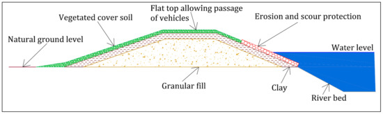
Figure 1.
Typical cross-section of a river dyke.
The granular structural fill supports the low permeability soil and is often needed to prevent burrowing animal weakening the structure by digging burrows that could open passages through the embankment resulting in serious damage in the event of a flood. The surface vegetation gives the embankment protection against erosion by rainfall and flood waters. To prevent animals from finding a suitable environment for excavating their burrows, it is essential that the embankment is covered only with grass and that no bushes or trees are allowed to grow on them. The top of the dyke is often a flat area that allows for access for maintenance inspections. The side exposed to the river, or riverside, often has additional erosion protection measures to resist the high flow and energy of a flood, such as large riprap rocks. The side away from the river, or landside, would typically only be vegetated, and it thus the most vulnerable area of the dyke.
3.2. Failure Mechanisms in Earthen Structures
A flood defense structure can fail due to a number of causes [8,16,17]. These causes are also known as failure mechanisms. The most common potential failure mechanisms in earthen dykes are:
- Overflow flooding caused by a water level in the river that is higher than the crest of the dyke, leading to overtopping. This can cause the structure to fail on the landside due to progressive erosion (Figure 2a).
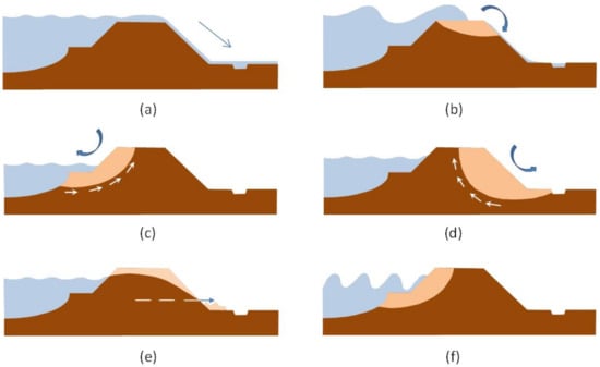 Figure 2. Failure caused by: (a) overflow, (b) overtopping, (c) macro-instability in riverside slope, (d) macro-instability in landside slope, (e) micro-instability caused by water filtration in the dyke body, and (f) erosion of riverside slope (adapted from [16]).
 - Overtopping: Progressive erosion of crest, landside slope and/or toe due to the force of the water in the event of overtopping or overflow (Figure 2b).
- Macro-instability in riverside slope consisting in sliding of riverside slope when the outer water level falls sharply after a high water event (outward macro-instability) (Figure 2c).
- Macro-instability in landside slope, consisting in sliding either due to water pressure exerted against the structure and increased pore pressure in the subsurface, or due to infiltration of the overflowing water when high water levels are combined with overtopping (Figure 2d)
- Micro-instability in the landside (or riverside) slope due to outward seepage through the structure (Figure 2e).
- Erosion of riverside slope due to wave action or currents (Figure 2f).
- Piping as a result of seepage through the subsurface [17], carrying sand particles with it and undermining the levee and siphoning beyond the foot of an embankment (Figure 3).
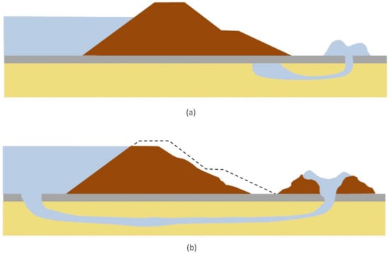 Figure 3. Failure caused by uplift and piping. (a) First and (b) second phase of the breaking of an embankment by siphoning (adapted from [17]).
 - Excavation of dykes by rodents (Figure 4).
 Figure 4. Failure caused by excavation by rodents (adapted from [16]).
Figure 5 show examples of failure of river dykes.
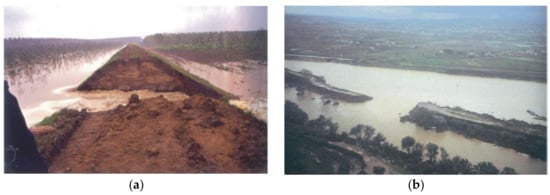
Figure 5.
Examples of failure of: (a) the dyke of river Po in Mantova province (Northern Italy) during the flood event of October 2000, and (b) the dyke of river Arno in Tuscany (Italy) during the flood event of October 1992 (adapted from [17]).
3.3. The Length Effect
The ‘length effect’ has major implications for the failure probability of a dyke segment: each segment consists of a contiguous series of flood defense structures that are the components of a serial system, similar to the links in a chain [16]. A chain is as only strong as its weakest link: if one link fails, the entire system fails. The longer a dyke, the greater the probability that there will be a weak spot somewhere. This is referred to as the length effect. In practice, the length effect is relatively strong for geotechnical failure mechanisms such as macro-instability and piping. A clear example of the length effect is shown in Figure 5a.
The length effect can be minimized by connecting adjacent segments with longitudinal reinforcement and drainage systems.
3.4. Increasing Strength
The composition of the soil (subsurface), dimensions (including the height and slope) and the revetment (facing on the surface) determine the dyke resistance to failure. Figure 6 shows an example of a dyke profile. The required protective height and width of a flood defense structure is determined by a number of factors. Overflow and overtopping, stability and uplift can all damage the revetment and erode the underlying structure, and can thus potentially cause a breach. These mechanisms also have a negative impact in terms of sliding in the top layer and macro-stability (Figure 6).
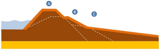
Figure 6.
Example of the design of the dyke profile based on three failure mechanisms. The thick orange line envelopes the solutions to the three failure mechanisms, and shows the design profile. The white dash lines show the initial profiles. (A) Overtopping (greater height, less steep landside slope, rougher slope). (B) Stability (less steep landside slope, widening of levee base). (C) Uplift and piping (heavier top layer and longer seepage length) (adapted from [16]).
There is however not always enough room to make an ideal dyke profile entirely of soil, for example when there are buildings, watercourses or other obstacles that are expensive or impossible to move. In such situations the flood defense structure will have to be strengthened using methods that take up very little space, such as reinforced soil structures with geosynthetics. Geosynthetic drainage systems can reduce groundwater pressure in the structure and allow the soil to retain more strength; geosynthetic barriers can replace thick natural low permeability soil with significantly thinner layers, thus reducing the structures footprint and increasing its impermeability (see Figure 7).
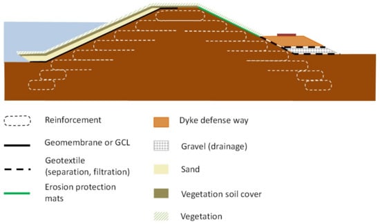
Figure 7.
Application of geosynthetics for dykes, schematic examples (adapted from [2,8]).
4. Main Applications of Geosynthetics in River Dykes
4.1. Geotextiles for Filtration
Filtration is one of the most common functions fulfilled by geotextiles in river dykes: it involves intricate interaction mechanisms between soil particles and geotextile fibers, hence it is certainly one of the most complex among all the functions fulfilled by geotextile products. Significant studies and research have been carried out around the world to evaluate the behavior of geotextiles used for soil filtration, both in the laboratory and in the field, with the ultimate goal to improve design criteria [18,19]. Geotextiles have better uniformity than granular filters. Geotextiles are subject to manufacturing tolerances under factory conditions, while granular filters are subject to the natural variability of soils and segregation during placement. Geotextiles rely on their extensibility and strength to remain continuous during placement and subsequent deformation. Nonwoven geotextile filters can be used both around the landside gravel drain and under the riprap protecting the upper portion of the riverside slope. Geotextiles used as filters in river dykes behave very similarly to geotextiles used in earth dams. The separation function is usually combined in those applications with the filtration function in horizontal, vertical and inclined filters and separation elements [8,20].
4.2. Geosynthetics for Drainage
Geosynthetics for drainage can be found in many applications in dyke design, as illustrated in Figure 8, such as in horizontal drains for the downstream slope, chimney and finger drain, vertical or sloping drain to compliment the barrier lining system inside the dyke body and internal drainage in homogeneous fill.
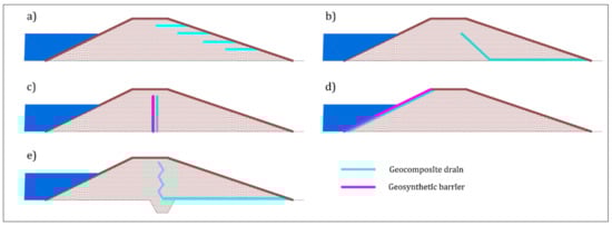
Figure 8.
Applications of drainage geocomposites in dykes: (a) horizontal drains for the downstream slope, (b) chimney and finger drain, (c) vertical or (d) sloping drain to compliment the barrier lining system inside the dyke body, and (e) internal drainage in homogeneous fill (adapted from [21]).
The US Army Corps of Engineers (USACE) [21] presents many situations where granular drainage layers can be incorporated in dykes, some of which are presented in Figure 9. In all these situations geosynthetics drainage systems can be designed in place of the granular ones.
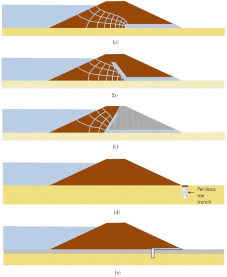
Figure 9.
Use of horizontal and inclined drainage layers to control seepage through an embankment (a) horizontal drainage layer, (b) inclined drainage layer for a homogeneous embankment, (c) inclined drainage layer for a zone-embankment, (d) typical pervious toe trench with collector pipe, and (e) pervious toe trench located beneath landward slope (adapted from [21]).
Geosynthetics for drainage are typically geocomposite drains, i.e., a combination of geosynthetics manufactured into a single product, usually comprising a drainage core with a geotextile filter factory bonded on each face. The drainage core is a 3 dimensional element (geonet, geomat, geospacer) (Figure 10), able to convey water flow along its plane.
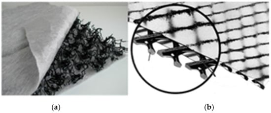
Figure 10.
Examples of (a) geocomposite drains with geomat and (b) geonet core.
4.3. Geosynthetics for Reinforcement
Geosynthetics can be used for increasing the stability of a dyke, or increasing its slope angles and thus reducing its footprint, by building reinforced fill structures. Engineering design procedures and construction methods are well established for these geosynthetic reinforcement applications. Reinforced fill is comprised of three basic components: fill, geosynthetic reinforcement and facing. The fill is usually a relatively clean granular soil material. The reinforcement is usually laid in horizontal layers. The facing is connected to the reinforcement and retains the face of the fill; it is usually made up of precast concrete elements, or by wrapping-around the geosynthetic reinforcement. Geogrids, woven/knitted geotextiles, and geostrips (Figure 11) are typically used for reinforcement in dyke construction.
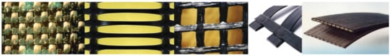
Figure 11.
Examples of (from left to right) woven geotextile, extruded geogrid, woven geogrid, bonded geogrid, geostrip.
The selection of the type of reinforcement and its specifications are undertaken based on design, as the reinforced soil body behaves similar to a structural element, on which the stability of the dyke ultimately depends.
Geosynthetic reinforcement can be incorporated at the base of embankments to aid in construction, reduce potential for foundation failure and excessive deformation, facilitate embankment construction on sloping ground, and to construct steeper embankment slopes.
Dykes frequently must be constructed across soft and compressible soil, with the potential for embankment failures (Figure 12). Basal geosynthetic reinforcement placed at the bottom of the embankment improves stability and may reduce the required width of the embankment (Figure 13), thereby reducing foundation preparation and embankment soil volumes.
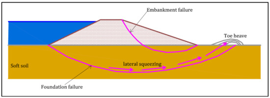
Figure 12.
Potential dyke failure when embankment is constructed on soft soil (adapted from [22]).
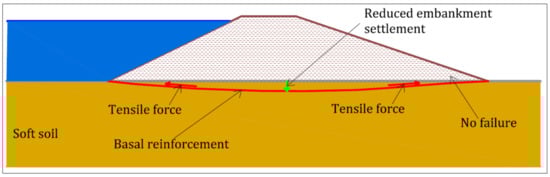
Figure 13.
Dyke failure prevented by using geosynthetic basal reinforcement. Tension that develops in the reinforcement (red arrows) provides the required stability and reduce embankment settlements (adapted from [22]).
Dykes can also be constructed across hill slopes. The natural soil conditions, steepness of the hillside, weight of the embankment, and seepage into the embankment can decrease embankment stability (Figure 14). Geosynthetic reinforcement can be incorporated in the embankment to improve stability (Figure 15). Geosynthetic reinforcement placed along the dyke axis can also be used to minimize the length effect [22].
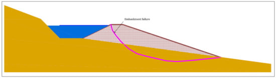
Figure 14.
Potential failure of a dyke constructed on a hillside (adapted from [22]).
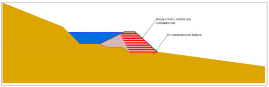
Figure 15.
The tensile strength provided by geosynthetic reinforcement can prevent the failure of a dyke constructed on a hillside, while reducing its footprint (adapted from [22]).
In many situations to increase the resistance of a dyke requires the enlargement of the existing embankment (Figure 16) [21]. The required embankment widening can be reinforced with geosynthetics. Depending on site conditions, multiple layers of reinforcement can be used to reinforce the embankment slope, which could permit the slope to be steepened, thereby reducing the foundation area to be prepared and the volume of fill in the embankment. The reduced land area required, reduced fill material costs, and increased embankment reliability provided by inclusion of geosynthetic reinforcement make incorporating geosynthetics a logical and economical choice. Figure 17 shows an example of reinforced soil dyke built in Tuscany (Italy).
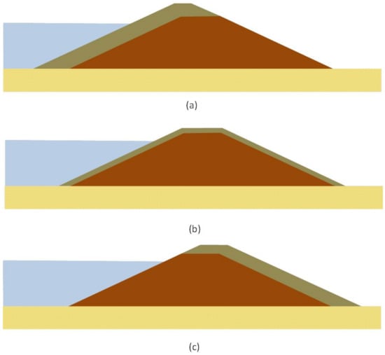
Figure 16.
Enlargements of existing dykes (a) riverside dyke enlargement, (b) straddle dyke enlargement, and (c) landside dyke enlargement (adapted from [21]).
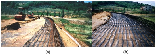
Figure 17.
Geogrid reinforcement of a dyke with steepened slope in Tuscany (Italy) (a) edge of the slope and (b) flat area.
While geosynthetic reinforcements placed across the dyke can afford the stability of each cross-section, additional reinforcement placed along the dyke axis can minimize the length effect, as shown in Figure 18. This longitudinal reinforcement can be installed during major refurbishment works on an existing dyke, and can be included in the original design for new dyke construction. The cost of the longitudinal reinforcement is negligible compared to the savings of avoiding potential dyke breaks due to the length effect, and consequent costs.
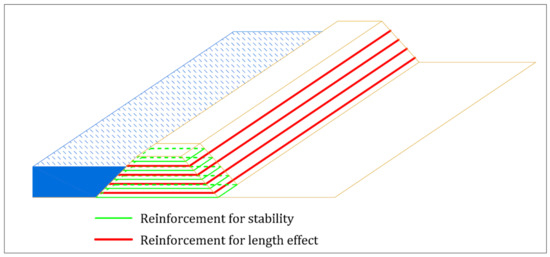
Figure 18.
Geosynthetic reinforcement used to afford stability of each cross-section of a dyke and for minimizing the length effect.
4.4. Geosynthetics for Stabilisation
Geosynthetics with stabilization function in dykes are typically used to construct roads and platforms to carry traffic on the top of the structure. As very often dykes are constructed from cohesive soils with a lot of fines, such as clays and silts, they are therefore relatively weak soils so their ‘trafficability’ is quite low. Any heavy vehicle passing on the top of dyke, especially during wet seasons characterized by increased moisture within top of the structure (spring thaw, heavy rain periods, etc.) will typically result in deep rutting (see Figure 19), making any further vehicle access impossible, especially during periods when the dyke could be experiencing a high-water level on the riverside or when local erosion/shallow slips of dykes occurs that require immediate maintenance to prevent further deterioration. From a management of dykes point of view lack of access for traffic is an unacceptable situation. Emergency vehicle access for urgent repair/maintenance works—which may require access for cranes, excavators, bulldozers or similar type machinery—requires continuous accessibility via a light but stable permanent pavement.
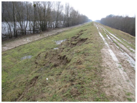
Figure 19.
Dyke top structure with rutting caused by traffic and with local erosion failures typical for wet seasons.
One of the most effective solutions to prevent rutting of the dyke crest is stabilization by geosynthetics of the unbound aggregate layer on the top of dyke, as shown in Figure 20. Geosynthetics for stabilization are in most cases biaxial/multiaxial geogrids or geocells (Figure 21) installed horizontally on the top of dyke structure. The stabilizing effect of geosynthetics is achieved by a reduction of horizontal and vertical movement of aggregate particles which counteracts deformation of that aggregate layer under applied load from vehicle traffic. It results in either prevention of fast rutting and can even provide a full flat profile of aggregate layer over a wet period. Axle load, bearing capacity of soils in the upper part of dyke and type of aggregate are parameters incorporated into design procedure, whilst thickness of aggregate layer and type of geosynthetic are the outcome of it. In individual cases it might be a bespoke solution designed for a specific type of machinery, e.g., heavy crane operating on the top of dyke. Often a geotextile separation layer is also included under the stabilized layer to further increase the redundancy of the system.
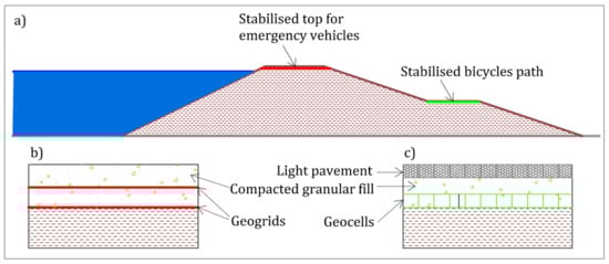
Figure 20.
Use of geosynthetics for stabilisation in dykes: (a) typical applications, (b) typical cross-section with geogrid stabilization, and (c) typical cross-section with geocell stabilization.
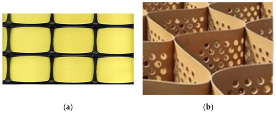
Figure 21.
(a) Typical biaxial geogrid and (b) typical geocell.
Another, very practical application of stabilizing geosynthetics in dykes is the construction of very light pavements for bicycles (Figure 20), which is becoming a very popular solution to attract bikers and to keep populations exercising and healthy.
4.5. Geosynthetics for Surface Erosion Control
Unlike in canals, it is not typical for a dyke to form the bank of a river. In most instances the dyke is placed at a higher level and at a distance from the natural river bed, and the water flow will only reach the river dyke during flood events. Hence the erosion of dykes by the permanent water stream or by the vessels in the river will not be discussed in this paper. Erosion control of riverbeds is discussed in [1,2].
Given these clarifications, in dyke engineering surface erosion control is related to both riverside and landside slopes, and it can be required for two main sources of erosion:
- Erosion caused by rainfall, and
- Erosion caused by overflow and overtopping of the dyke (Figure 2).
Rainfall erosion can occur both on the whole landside slope and riverside slope, and erosion due to overtopping can occur in flooding conditions on the landside of a dyke.
Erosion control against rainfall on the riverside or landside slope of a dyke is exactly the same as on any slope, while erosion control for overtopping is typical of dyke engineering. Many failures of dykes have been triggered by overtopping and consequent failure of the unprotected landside slope. Failure mechanisms due to overtopping have been shown to start at the landside slope, and then progressively involve the dyke body. The need to protect the landside slope is therefore evident.
Overtopping of a dyke can create erosion damage on the crest and on the landside slope, depending on the local boundary conditions. Overtopping often occurs with dyke saturation, which weakens the structure and makes it easier for the water to flow over the crest, subsequently cutting into the landside slope surface or into the toe of the dyke. The primary erosion protection mechanism for dykes against hydraulic loads is grass cover. The resistance of vegetation against erosion depends mainly on the grass, which must be sufficiently dense to prevent soil particles from passing through it and sufficiently robust to prevent bare spots from appearing in the vegetated area. To gain immediate protection and strength, an effective solution can be provided by geosynthetics for erosion protection (geomats, reinforced geomats, geoblankets). In the case where the grass cover does not give full coverage, or where hydraulic impact has locally removed the grass, the erosion control product bridges the bare spots.
Geosynthetics create a physical barrier which can absorb the impact of water and wind on soil, resulting in the prevention of soil loss and enhancing vegetation growth. These products are flexible and environmentally friendly; the installation is easy and fast and they can be applied directly on slopes and along river and canal banks. Examples of geosynthetics for erosion control are given on Figure 22. They promote vegetation growth and increase the long term resistance of the grass cover to the potential hydraulic loads from a river in flood or from water flow on the landside during overtopping by reinforcing the grass root zone. However, after installation some time is needed to allow the roots to grow through the erosion control product into the soil below (Figure 22).
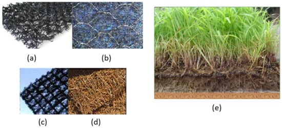
Figure 22.
Examples of geosynthetics for erosion control. From left to right (a–e): geomat, steel mesh reinforced geomat, geogrid reinforced geomat, geoblanket and resulting vegetation growth.
Experience has shown that vegetated dykes can withstand limited overtopping with little or no damage. Research utilizing actual vegetation on test embankments and experience with vegetated spillways has allowed quantification of the hydraulic loads required to generate failure on a vegetated embankment face [23]. The results of this research and experience have been used to develop simplified computational procedures for use in predicting an acceptable amount of overtopping flow during a major flood event. Allowing overtopping of dykes to the point of incipient failure of the slope protection is consistent with the U.S. Natural Resources Conservation Service approach of requiring passage of the design flood without breach of the embankment.
During overtopping flow the vegetation can provide protection against the initiation of concentrated erosion that leads to head cut development and breach. For larger flow rates, vegetation may delay breaching sufficiently to permit evacuation of downstream areas [24]. Vegetative cover is most viable as a protection method in humid climates that receive sufficient moisture to establish relatively dense, uniform turf grasses without supplemental irrigation. Good maintenance of the cover is essential to achieve significant protective benefits. Vegetation provides protection to an embankment in two functional ways: (1) protection of the soil surface by reduction of velocities and stresses at the embankment boundary as a result of the coverage provided by stems and leaves that lay down in the flow and blanket the surface; (2) the reinforcement of the underlying soil due to the presence of roots.
Geosynthetic reinforced grass can resist significantly higher duration flow velocities compared to unreinforced grass; moreover the time before failure occurs is extended when vegetation is reinforced. A good grass cover can typically withstand flow velocities of 4.5, 3.2 and 2.8 m/s for durations of 1, 5 and 10 h respectively, while for grass reinforced by a 20 mm thick TRM these velocities are typically increased to 6.0, 5.5, and 5.0 m/s [25].
4.6. Geosynthetyics for Protection against Rodents Excavation
Beavers, nutria, badgers and other rodents or digging animals can sometimes cause significant damage on slopes of dykes. In isolated cases, such damage caused by these animals could lead to an increased risk of global slope failures with serious consequences of flooding for the communities living in the area. Cavities created by digging animals (Figure 23) can be of high risk for the stability of the dyke. The highest risk is beavers digging through the low permeability layers. An opening through these layers leads to increased flow through the dyke, ultimately causing erosion and water seeping through the embankment all the way to the landside. Most critical failures consist in partial or total collapse of the embankment by sliding.
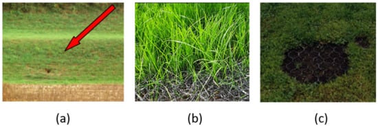
Figure 23.
Badger excavation at dyke toe and protection against rodent excavation with reinforced geomats (adapted from [26]).
Due to changing climate conditions, recent studies show an increase in the population of beavers, nutria and other rodents in vast regions of central Europe over the last 15 years, while the Netherlands’ beaver population is expected to grow from 700 to 7000 by 2032 [26].
Safe and durable protection against rodent intrusion in dykes can be achieved by lining the dyke slopes with geomats reinforced with steel mesh (Figure 23). The strength of the steel mesh will act as an impenetrable barrier to the animals who will not be able to dig a hole through the steel mesh, while the geomat will provide the erosion protection function during flooding events.
An intervention against rodent intrusion was implemented in Germany along the Odra Dyke, District Sophienthal, Brandenburg, in 2013, in cooperation with the State Agency for Environment, Health and Consumer Protection Frankfurt/Oder and the Water and Dyke Association Oderbruch [26]. A reinforced geomat for beaver protection was installed in a 200 m long dyke stretch, near the community of Sophienthal. This project also shows the multi-functional use of geosynthetics in dykes: a geosynthetic clay liner (GCL) was placed for waterproofing of the riverside slope, a polyester geogrid was placed at the base of the embankment for basal reinforcement, and reinforced geomats were placed on the riverside and landside slopes for protection against erosion and rodents excavation.
4.7. Geosynthetics for River Training Works
Longitudinal dykes can be protected, particularly in curves, with groins built perpendicular to the river flow (Figure 24) [2]. Such structures must be resistant against high flow forces. The groins can be built using geosynthetic mattresses, geosynthetic tubes and geosynthetic containers. In addition, a filter geotextile underneath the groins is an essential component of the system that contributes to a long lasting training structure. The weight of the containers is typically chosen according to the hydraulic load and the installation done to avoid gaps in between the elements. These structures may also get an armor layer of steel or geosynthetic mattresses or armor stones (riprap) if necessary. The structures can also use cheap local material for the main structure fill with short transportation distances and thus reduced related impact.
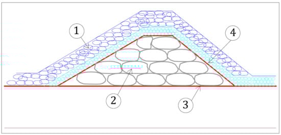
Figure 24.
Groin construction with geosynthetics: (1) hard armor or geosynthetic containers; (2) geosynthetic containers for the core; (3) geotextile filter; (4) steel mattresses or armor stones (adapted from [2]).
4.8. Geosynthetics in Barrier Systems
To avoid failures due to water filtration inside and below a dyke, or due to erosion on the riverside slope, the most effective passive method is to separate water completely from the soil and thus prevent any interaction between the water and soil [1]. This can be done using barrier materials, which, also serve as protection for the underlying soil. Barrier layers can be provided by geosynthetic material, namely polymeric or bituminous geomembranes or geosynthetic clay liners (GCL). The advantage of these systems is the flexibility to adapt to deformations developing after the lining installation [1].
The use of geosynthetics also allows for the construction of a dyke out of higher permeability fill than would normally be adopted for dyke construction, in order to reduce seepage and internal erosion [12].
There is often a variety of locally available materials used to construct dykes, as local soils are the most cost effective construction material. However, the material is often very heterogeneous and its permeability can be variable. Many of these dykes have been subject to reconstruction, additional sealing and other improvement [3] as local weak points can lead to the failure of the entire structure.
Some potential applications of geosynthetic barriers in dykes are summarized in Figure 25.
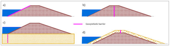
Figure 25.
Some applications of geosynthetic barriers in dykes (adapted from [27]): (a) on the riverside slope; (b) vertically placed in the dyke body; (c) in the cut-off diaphragm below the dyke body; (d) vertically placed in the dyke expansion.
Near surface slips resulting from a quick drop in the water level on the riverside, and causing superficial sliding of the riverside slope, can leave the clay core unprotected against erosion. In the case of geomembranes or GCLs, placed on the riverside slope (Figure 25a), near-surface slips are also critical, but can be repaired more easily than along softened, partially eroded clay [8]. A specific requirement for barriers is a sufficient resistance against impact forces. Armor stones have to be laid on the barrier material with care [1]. In these cases a geomembrane requires protection provided by a nonwoven geotextile.
Brandl [8] also points out that geosynthetics have proved suitable as an alternative to clay cores in the body of a dyke.
Installing a barrier on the waterside of the dyke may not always result in the desired effect. An additional aspect to consider is the contact to the in situ soil layer at the upstream toe of the embankment. If the water is able to flow below the barrier and into the dyke, the effect of the lining will be negated. The seepage line in the embankment will ultimately reach nearly the same level as without the barrier. The only advantage is potentially to gain some time until this condition is reached, depending on the permeability of the embankment. If there is no soil layer with low hydraulic conductivity at the foot of the dyke, additional measures are necessary, e.g., cut-off diaphragm to a sufficient depth [1] (Figure 25c).
Cutoff walls can be constructed using interlocking geomembrane panels, which can be installed in slurry-filled trenches. The geomembrane panels are inserted with the aid of guide frames. The geomembrane panel joints are typically self-sealing with proprietary interlocking features. In some soil conditions, the geomembrane panels can be installed using a vibratory hammer and insertion plate, thus eliminating the need to excavate a slurry trench. The geomembrane for cut off walls are usually made of HDPE, with a thickness of 2–3 mm.
In case of dyke expansion, the expansion can be made of locally available soil with relatively high permeability; yet the expansion can be made impervious by placing a geosynthetic barrier vertically in the expansion on the dyke crest (Figure 25d).
Other impervious linings such as concrete slabs, concrete mattresses or asphalt layers are too stiff to adjust to subbase deformations. They will bridge indentations caused, e.g., by sub-erosion and thus no warning is given until a cavity under the lining has become too large and the whole structure collapses [1].
Significant experience on the use of GCLs as impermeable surface lining in dykes has been gained in Germany where following the Elbe River floods that took place between 2002 and the end of 2005, about 150 levee reconstruction projects are known to have been carried out in which about 700,000 m2 of GCLs have been employed [10]. A schematic application of GCLs as an inland levee sealing system against flooding from rivers is illustrated in Figure 26. The dimensioning of GCLs in this case is covered in [28] and the installation of a geosynthetic clay liner generally follows [29].
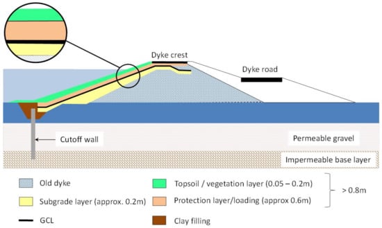
Figure 26.
Application of a geosynthetic clay liners (GCL) in the course of dyke refurbishment works (adapted from [30,31]).
The hydraulic properties of GCLs and Geomembranes, compared with various lining materials are included in Table 1 [32].

Table 1.
Properties and flow rates through lining materials including geosynthetic clay liners and geomembranes for an applied hydraulic head of 1 m for porous materials. The difference in pressure applied between both faces of the geomembranes and multicomponent GCLs is 100 kPa.
5. Economic Advantages of Construction Using Geosynthetics
The use of geosynthetics in civil engineering applications often provides financial benefits by reducing the cost of imported materials, reducing the amount of waste, and generally provides more efficient use of resources compared with traditional solutions that use soil, concrete, and steel [35]. The cost, schedule, and risk reduction benefits provided by using, for example, geosynthetic reinforcement, have resulted in these products having been used for decades to improve stability of dykes. Based on a review, four types of cost savings have been identified [36]:
- Reduction of the quantity or need for select imported soil material,
- Easier and/or accelerated construction,
- Improved long-term performance, and
- Improved sustainability.
The questions of the reduction of the quantity or need for select imported soil material and improved long-term performance are discussed in the following subsections. Improved environmental benefits of the use of geosynthetics, contributing to sustainability, will be discussed in Section 6 of this paper.
5.1. Reduction of the Quantity of Soil Material
To reduce the quantity of natural soil materials required, geosynthetics often replace the given soil and rock materials at a material and installation cost that is less than that of the natural-material alternative. Furthermore, geosynthetics are often used in geotechnical systems and, due to improved performance efficiency, may decrease the volume of other geotechnical materials used in that system. In many cases the cost benefit is such that the use of geosynthetics is now the standard practice [36].
Normal flood embankments along rivers are not designed for overflow loads, except special designed overflow sections. Some technical code for flood protection dykes along rivers exclude the protection of the landside embankment from technical standard structures because of the high costs and poor experience with such structures [37]. Thus, overflow loads mostly lead to a very rapid and complete failure of the dyke structure forming a dyke breach with lengths from few meters to several hundreds of meters. A huge part of the damage that occurred due to dyke breaches in Germany in the past decades could have been avoided by focusing the application of overflow protection for the structures. In addition, [37] states that one major issue cited against the incorporation of overflow dyke structures are perceived high costs. According to them this issue can be addressed by using designs incorporating geosynthetics.
An example of how geosynthetics can economically contribute the construction of overflow dyke structures was presented in [13]. The USACE conducted extensive testing and pilot research programs to find alternative solutions for dyke overflow protection measures in order to reduce the costs and provide identical or better performance than traditional hard armoring systems such as rock riprap and concrete for hurricane and storm damage risk reduction systems. The study showed that a high-performance turf reinforcement mat (HP-TRM) solution is a more cost effective and environmentally friendly solution than traditional hard armor solutions.
The case study of the construction of dykes on embankments constructed on soft soils was presented by [36]. In the study dykes at Craney Island, Virginia, USA, construction, without reinforcement using geosynthetics would have required 8 to 10 times the volume of soil, as the fill would be pushed down into the soft soil below in order to build the structure above the surface. When reinforced embankments using geosynthetics were built on that project, less than one times the volume of soil was lost for one volume to construct the structure above the surface. Thus for very weak soils, geosynthetics used in reinforcing the embankment significantly reduced the amount of displacement of the foundation and thus the loss of material, resulting in a significant saving.
5.2. Reduction of the Need for Select Soil Material
The EU Regulation 305/2011 [38] lays down harmonized conditions for the marketing of construction products and particularly recommends predominantly using secondary materials as construction material. The demonstration of how the use of geosynthetics can improve the functionality of dykes constructed with fine-grained dredged materials as a replacement for standard dyke cover material was studied [3]. In this context geosynthetics contribute to reduce the cost of construction by allowing the use of inert waste products as part of the structural fill.
In many places in the world, gravel for the core and rock as armor is simply not available and concrete (for armor elements) is too expensive. In such cases, geotextile bags or containers offer an alternative solution. Local fill material is filled in geosynthetic containments to build the core of the river training structures. Using cheap local material for the major volume of the structure will result in lower costs with the same benefit [1].
More generally, a better use of residues and waste in engineering works is important to reduce the exploitation of natural material and to preserve the environment. The combination of geosynthetics with such residues may provide less expensive and concomitantly more environmentally friendly solutions [39].
5.3. Improved Long-Term Performance
The long term performance of geosynthetics in their application can both be discussed from the point of view of the product performance, and of the application in which the geosynthetics are installed. Indeed, geosynthetics, by their use, contribute to the increase of the lifetime of the application, as evidenced by the references mentioned in the following.
5.3.1. Durability of Geosynthetics
UV resistance is a key parameter for the durability of geomats and geoblankets for erosion control, especially in areas with lower chance of full vegetation, and for critical applications such as storm water management and flood protection [13]. Accelerated UV tests on geomats for a period of 3000 h and 6000 h have proven the long term durability of these geosynthetics for erosion control [13].
Reference [40] mentions the various ageing mechanisms that the GCLs can face while installed in dykes: stress during installation, surface resistance against abrasion due to rip-rap, washout of bentonite in relation with hydrodynamic action, freeze-thaw cycles, hydration-desiccation cycles combined with cation exchange that lead to significant increase in the hydraulic conductivity of the bentonite in the GCL, or root penetration. Proper design, and installation of GCL however allow to overcome those potential aging and failure mechanisms as emphasized by feedbacks from excavations at dykes. In particular a minimum 0.8 m thickness of cover soil is recommended. Fleischer and Heibaum [40] report on the excavation at three dykes of GCLs installed respectively in 1994, 2001 and 2004, thus 4 to 12 years after installation. Where the soil cover nature, thickness and slope were adapted, as well as the vegetation on top of the GCL and cover soil, good performance along time of the GCL was noticed.
Multicomponent GCLs are GCLs onto which is attached a film, coating, or membrane that decreases the hydraulic conductivity, protect the clay core, or both [41]; these geosynthetics could find some applications in dykes to solve some of the issues previously presented. Some hydraulic properties of multicomponent GCLs are given is Table 1.
5.3.2. Increased Life Span Thanks to the Use of Geosynthetics
Most of the applications in which geosynthetics are used are designed to perform at least equally to traditional design solutions. Part of the reason geosynthetic solutions have improved performance over traditional designs is that they work better than the geotechnical material they replace. The performance improvement is gained by using manufactured materials with known properties as compared to the relative high variability of soils and requirements for monitoring of the installation/compaction of soils to allow for their desired properties to be achieved in the field. In some applications geosynthetics also improve the performance of geotechnical material [36].
Haselsteiner et al. [37] mention that measures involving geosynthetics lead to a retardation of the flooding of the hinterland located behind the dyke and additionally a complete failure was avoided. Both effects result in a reduction of flood damage and in gaining more time for taking other flood protection measures. In spite of the fact that no design specification or standards were created, in comparison to commonly used overflow protection measures such as riprap or just flat embankment inclinations, geosynthetic overflow structures are an effective and efficient solution.
In addition, it was shown, among other conclusions, that HP-TRM maintained with engineered earth anchors (EEAs) can increase the safety factor of the armoring system against hydraulic forces and also provide slope surface stability [13].
5.3.3. Geosynthetics and Seismic Resilience
The good performance of geosynthetic-reinforced soil walls and slopes during earthquake has been documented widely in the literature [42]. In Japan, the greater seismic resistance of these structures compared to conventional retaining wall structures has led to their increasing use for new permanent structures and to replace conventional structures damaged in earthquakes. By extension, dykes constructed with geosynthetic reinforcement would be more resistant to seismic loading than those constructed from traditional materials and the geosynthetic reinforcement will provide additional tensile strength and resilience in the structure.
6. Mitigating Greenhouse Gases Emissions Using Geosynthetics
Two categories of actions are required to tackle climate change and its effects: (i) mitigation to reduce greenhouse gases (GHG) emissions and (ii) adaptation. Geosynthetics can make a contribution to mitigation by reducing GHG emissions from construction and operating infrastructure. In fact, the ecological advantages of construction methods using geosynthetics are well known, the use of geosynthetics can dramatically reduce emissions from soil that needs to be excavated, transported, and put in place [43].
The carbon footprint is a measure of total GHG emissions caused directly or indirectly by a person, organization, event, or product. The carbon footprint can include emissions over the entire life of a product or construction. Embodied carbon (EC) is an indicator of cumulative carbon emissions used in the solution adopted. Life-cycle assessment (LCA) is a tool for measuring the environmental impact of products or systems over their lifetime. It considers the extraction of raw materials, production, use, recycling, and disposal of waste [43].
The past few years have seen an improved mastery of techniques of LCA in the field of geosynthetics. The latest calculations [44,45,46] are indicative of the progress made in this field, in which an ever-more constructed standard approach is evolving by using EC values representative of geosynthetics [47] and by comparing the EC values for entire construction solutions. Thus, results are recognized and trusted when the conclusion indicates that solutions using geosynthetics significantly reduce environmental impact.
The sustainability of materials and processes is commonly assessed by calculating the carbon emissions (CO2) generated that can be used as “short LCA” for the ecological evaluation [44]. Taking into account the extraction and production of the used construction materials, loading, transport and installation, the cumulated energy demand (CED) and CO2 emissions are determined for each of the construction alternatives.
Although this is a simplification, the ease of calculation encourages comparisons between solutions and makes such assessments accessible, transparent, and repeatable so that the CO2 emitted can more easily be counted towards industry, national, and international targets [44]. Some studies have incorporated other indicators such as cumulative energy demand, climate change, photochemical ozone formation, particulate formation, acidification, eutrophication, land competition, and water use. Such calculations were made for various applications [48].
The use of geosynthetics results in massive improvements to CO2 savings as opposed to nearly all alternative civil engineering materials used [49]. In the particular context of dykes the example of the comparison of an external sealing for a river dyke on the Kinzig (southwest Germany) is given [50]. The use of a GCL is compared to the use of a compacted clay liner (CCL) with an average thickness of 0.625 m. The comparison turns out in favour of the GCL. The difference in the cumulated energy demand of the two sealing systems is, however, comparatively insignificant. A medium transport distance of 35 km (one-way) was assumed for the mineral barrier material, which greatly impacts the CED for the required sealing material of 45.000 tons (see Figure 27). For the GCL the main share in the CED is the polypropylene (PP), which at a surface weight of 0.69 kg/m2 PP (including 6.2% overlapping) is a major factor. When comparing the two sealing systems, the transport distance for the mineral sealing material is the decisive parameter. If the place of extraction is on-site or very near to the place of installation, then the CCL—mostly because it has no energy content (feedstock)—can hardly be improved upon. In the case of the GCL, the main part of the CED is the energy content (feedstock) of the polypropylene (ca. 53%). The transport distance for the GCLs from the manufacturer’s plant in Espelkamp to Offenburg (580 km) is, in comparison as regards the CED compared to the PP granulate material, of hardly decisive consequence (ca. 8.5%).
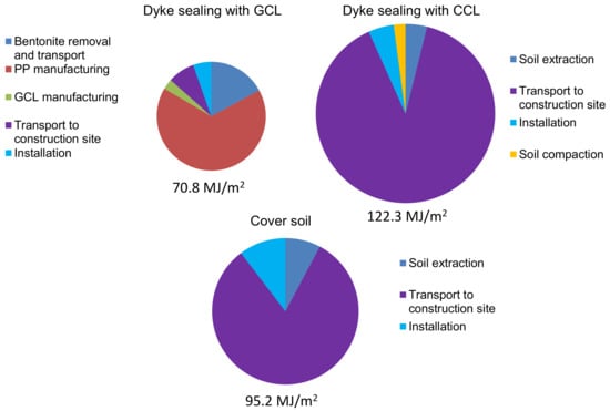
Figure 27.
Comparison of cumulated energy demand for GCL and compacted clay liner (CCL) dyke sealing systems (adapted from [46]).
The covering soil which has to be put in position as weather protection for both barrier materials (here: d = 0.8 m), is 97 MJ/m2 with an assumed average transport distance of 20 km for both cases studied, in particular when comparing these systems with other systems, of quite considerable consequence. The distribution concerning environmentally relevant CO2 corresponds approximately to the CED, the GCL has a CO2 emission of 4.0 kg/m2, the CCL of 9.9 kg/m2 and the covering soil is entered in the CO2 balance sheet with 7.9 kg/m2 (see Figure 28).
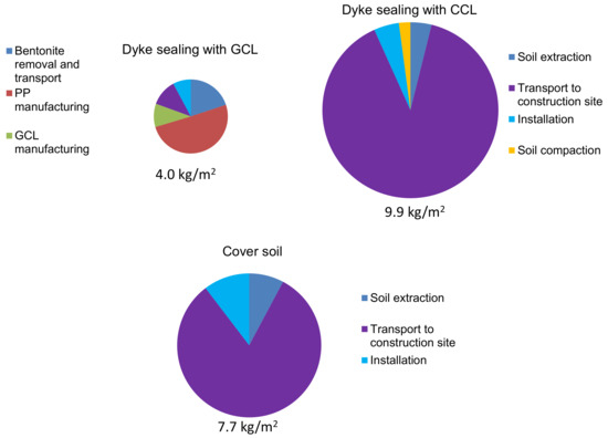
Figure 28.
Comparison of CO2 emissions for GCL and CCL dyke sealing systems (adapted from [46]).
In bank protection works, the carbon footprint of double twist wire mesh solutions is twice as little as riprap and can be improved more when locally available stones are used, which is usually the case as the diameter of stone used in the filling of the mesh is usually small. In this case the impact in terms of carbon footprint was 6 times less than for riprap for the case study presented [51].
7. The Minimum Energy Performance Concept
A key concept in sustainability of constructions is the minimum energy performance [52]: according to the EU Directive on the Energy Performance of Buildings, cost-optimal energy efficiency levels for buildings need to be ensured, where cost-optimal is the level of energy efficiency at which the total cost of the life cycle is minimized, taking into account the costs of construction, energy and maintenance [53].
Extending the concept from buildings to civil engineering constructions, such as river dykes, sound engineering practices would require the designers to understand how to use “living” and “inert” materials together by best combining both types of materials.
The challenge is to identify a system capable of providing the required resistance and to be able to incorporate the most appropriate solution, which would be that one defined by the cost-optimal energy efficiency levels; in civil engineering constructions this can be broadly defined as the minimum amount of intervention on the environment, which is required to solve the problem, ranging from the lowest level of no intervention up to the highest energy level, which may necessitate, as example, the construction of massive concrete structures.
Given the above outlined reduction of the quantity of soil material, reduction of the need for select soil material, improved long-term performance, durability, increased life span, and mitigating greenhouse gases emissions, Geosynthetics can be considered as one of the best ways to design according to the minimum energy performance approach, affording in most cases the cost-optimal energy efficiency level of the project.
8. Advantages and Disadvantages of the Use of Geosynthetics in Dyke Engineering
As discussed above, the use of geosynthetics in river dykes has many advantages, in terms of technical properties, ease of construction, economy, and environmental impact.
In this section the potential disadvantages for the use of geosynthetics in river dykes are discussed, based on recent research and experience from existing projects.
8.1. Geotextiles for Filtration
To the authors’ knowledge there are no reported failures in literature of geotextile filters used in river dykes. The potential disadvantages of geotextile filters, compared to the traditional granular filters, lies in the risk of clogging and/or blinding due to fine particles being entrapped inside the geotextile and/or accumulated on its surface, to a level that the filtration capacity and the permeability are impaired. Recent results from excavation of geotextile filters have been reported [54].
It has to be noted that geotextile for filtration in earth dams has been one of the earliest applications: the first large earth dam using geosynthetic materials, Valcros dam, was built in 1970 in France. At that time the geotextiles were designed as a filter on the upstream slope between the rocks and the earth fill and on the downstream slope around the main drains [55]. The behavior of these geotextiles is fully documented because several excavations and investigations were carried out 6 years [56] and 21 years after installation [57]; the geotextiles at Valcros dam are still in operation without any impair factor to their filtration capacity after over 50 years.
Over 40 years of research into geotextile filters has led to the publication of several design criteria, which have been summarized in the ISO TR 18228 [58] series of standards for design of geosynthetics, including the filtration function.
Designing geotextile filters in river dykes according to this standard would prevent the potential risk of clogging and/or blinding, thus eliminating the only potential disadvantage for the use of a geotextile filter.
8.2. Geosynthetics for Drainage
Geosynthetic drains have very think profile (up to 20 mm) compared to granular drainage blankets (whose thickness is of the order of 0.5–1.5 m). Nevertheless the water flow inside geosynthetic drains is typically turbulent with much higher velocity than the filtration flow occurring in granular filters. Hence the flow rate of geosynthetic drains is very high even with their reduced thickness.
Recent research on geosynthetic drains has shown that the draining core can be subject to thickness reduction due to compressive creep over the entire design life, and due to the intrusion of the geotextile filters into the draining core, which would reduce the available flow capacity. This is a potential disadvantage compared to granular filters, which are not subject to the negative effects of long term overburden pressure.
A decrease in the available flow capacity due to chemical or biological clogging of the draining core has however been shown to not be of concern when fresh water is being transmitted, such as in the case of river dykes.
Research on geosynthetic drains has led to the development of test standards for the evaluation of their short and long term properties: water flow capacity in standard conditions (ISO 12958-1 [59]) and in operational conditions (ISO 12958-2 [60]), compressive creep testing (ISO 25619-1 [61]) and accelerated compressive creep testing with the Stepped Isothermal Method (SIM) (ASTM D7361 [62]).
These tests are the base for the design criteria for geosynthetic drains, which have been summarized in the ISO TR 18228 [58] series of standards for design of geosynthetics, including the drainage function.
Designing geosynthetic drains in river dykes according to this standard, taking into consideration the overburden pressure, would allow for the selection of a product able to provide the required flow rate at the end of the design life, with the prescribed factor of safety on the available drainage capacity.
Hence the potential disadvantage of geosynthetic drains compared to granular filters, due to compressive creep and geotextiles intrusion, can be easily overcome through sound engineering design.
8.3. Geosynthetics for Reinforcement and Stabilisation
To the authors’ knowledge there is no potential disadvantage in the use of geosynthetics for reinforcement and stabilization in river dykes.
Obviously, the stability of reinforced or stabilized soil structures shall be designed taking into account all the potential limit states and failure mechanisms, including the water induced ones: for river dykes, the stability analyses in case of rapid draw-down shall always be carried out.
8.4. Geosynthetics for Surface Erosion Control
The erosion control function is complex, since the performance depends both on the geosynthetics that are used and on the establishment of the vegetation.
Given that the establishment of vegetation would require, in any case, the correct mixture of soils, the proper selection of seeds, the possible use of mulch, and the maintenance during the first growth season, the only potential disadvantage in the use of geosynthetics could be the difficulty to select a product that wouldn’t impair the growth of vegetation while continuously providing erosion protection and root reinforcement.
The ISO TR 18228 [58] series of standards for design of geosynthetics, including the design of geosynthetics for the erosion control function, both on slopes and on river/channel banks, allows for the selection of the geosynthetics which can afford the required resistance to both the design water velocity and the design shear stresses applied by the stream.
8.5. Geosynthetics in Barrier Systems
The main barrier materials used in dykes engineering are GCLs. GCLs when used in river dykes are however subject to specific failure mechanisms. These are summarized as previously stated in [40] and include:
- Careful attention needs to be paid to panel overlaps as these are potential points of weakness in the barrier, so good construction quality assurance is critical.
- GCLs in dykes should not be exposed directly to hydraulic loads, as this could wash the bentonite out of the GCL over time. GCLs are therefore typically covered with a soil layer, minimum 800 mm thick.
- GCLs subject to freeze and thaw cycles can develop increased hydraulic conductivity; again the soil cover layer will usually prevent this failure mechanism.
- GCLs can be subject to root penetration from vegetation that establishes on the embankments. Sufficient cover depth, typically 0.8m, is usually specified to mitigate this risk.
- The bentonite in a GCL can be subject to cation exchange, reducing the swell capacity of the bentonite and thus the hydraulic conductivity. This effect is usually exacerbated by wet/dry cycling. As such designers should be aware that the GCL hydraulic conductivity is likely to increase over time and incorporate measures to deal with this in the design.
Von Maubeuge and Ehrenberg [63] discussed the benefits multicomponent GCLs could bring, by limiting bentonite erosion and wet dry cycles and also potential cation exchange with the soil covering the GCL, as could be expected in a dyke environment, thus further extending the design life of the material. The polymer layer in the multicomponent GCL will also form a barrier to root penetration, as a geomembrane would, which has been highlighted as a risk to the use of GCLs in dykes [40].
8.6. Environmental Benefits of Geosynthetics
Geosynthetics are designed to last: most geosynthetics can be supplied with certificates of conformance for an expected duration in excess of 100 years. It is essential that the design life of geosynthetics is at least equal to the design life of the structure they are incorporated in. As previously presented, the design life of geosynthetics used in geoenvironmental applications is subject to many factors. By taking these factors into consideration, and by using internationally accepted standards of specification, design and installation, their ability to function can be relied upon for well over the expected design life of these structures. Ref. [64] evaluated durability testing data collected over a 17 year period on HDPE geomembrane samples. Geomembranes used in applications such as river dykes will experience temperatures below the long-term average ambient temperatures. For a site with an annual average earth temperature of 15 degrees Celsius the expected life of a suitable specified and installed geomembrane would be well over the 100 years specified in CE marking. Strict quality control along the production chain but also during installation, for which procedures have been developed and are in use, is also a key factor.
The construction activities based on construction methods that do not involve geosynthetics have contributed significantly to global warming and associated geoenvironmental instabilities, such as soil erosion, hill/riverbank/coastal slope instability, ice/glacier melting, floods and sea-level rise, worldwide [65]. Carbon emissions associated to construction with geosynthetics has been shown to have a comparatively limited impact, so that in addition to bringing solutions that contribute to limiting the effects of floods, geosynthetics also, in a virtuous circle, contribute to limiting carbon emissions during construction of these measures. The use of geosynthetics also provides an increased durability and resilience to infrastructure, which also results in less carbon emissions long term due to the infrastructure being able to function for a longer time.
Finally, education, in particular through the Educate the Educators program of the IGS, is essential in offering undergraduate civil engineering students exposure to geosynthetics. It does this by providing Geotechnical Engineering university professors with the content and pedagogical tools needed [66]. The knowledge and knowhow thus capitalized over the years in terms of designing and building with geosynthetics can be used to the best and largest possible extent to ensure the longest duration of works and lowest impact to the environment.
9. Summary
In the context of climate change and the resulting expected increased frequency and magnitude of natural disasters, longitudinal dykes, constitute one of the most often used active structural methods to control the course of a river
Dykes are commonly made of different natural materials. They can also incorporate geosynthetics. Literature on the appropriate use of geosynthetics in dykes and their advantages in this context is sparse. The objective of this review paper was thus to compile a synthesis of the existing literature on this topic to address the many ways in which geosynthetics contribute to sustainable construction of dykes and thus contribute to water systems management.
A brief presentation of what geosynthetics are and the functions they can fulfil was given in Section 2 of this paper.
Section 3 gave a brief overview of dyke structure, when built from granular materials, and the typical failure mechanisms in earthen structures that are commonly encountered due to the action of water. Based on the review of these failure mechanisms, solutions incorporating geosynthetics, that contribute to increased resilience of dykes by increasing their strength and their longevity, are presented.
The main applications of geosynthetics in dykes were presented in Section 4. The advantages of using geotextiles filters, and the various locations in a dyke where they can be used were detailed. Insight was then given in the applications of geocomposites for drainage, that can replace granular materials efficiently to fulfil this function. The applications of reinforcement and stabilization were then addressed. Again the importance of the adaptation of the design and of using the right materials at the right location to optimize the performance was emphasized. The enlargement of dykes was discussed in this section.
Surface erosion control can be a major issue in dykes, both on the riverside and the landside. This topic is critical as overtopping of dykes during extreme intensity floods is thought to represent one of the main risks of failure of these structures. Various alternatives incorporating geosynthetics were presented.
The use of geosynthetics to ensure protection against rodents was also discussed.
Finally, details were given on the way geosynthetic barriers can be incorporated in dykes in order to separate water from soil in the structure and thus avoid failures due to water infiltration, was presented.
Through the presentation of the various potential uses of geosynthetics in dykes, emphasis was thus put on the many ways geosynthetics contribute to reduce the risk of failure of dykes and thus increase their resilience.
As further shown in Section 5, in addition to the technical benefits of construction with geosynthetics, the use of geosynthetics also results in economic advantages for a project. The paper has demonstrated how construction with geosynthetics can result in a reduction in the quantity of soil material required to form a dyke, and even of the type of fill required, making it possible to use dredged materials, coal combustion products or even residues. The increased life span of construction that results from the use of geosynthetics also contributes to the implementation of economies that can be significant.
In addition to the environmental benefits resulting from the reduction in quarrying of granular fill material, mitigation of greenhouse gas emissions during construction can be obtained and quantified as shown in Section 6 of this paper.
This review paper has illustrated the many possible contributions of geosynthetics to the construction of sustainable river management, not only by allowing the implementation of more economic construction methods, but also with increased durability, to be able to withstand the extreme stresses related to climate change that these structures are going to be expected to endure. Geosynthetics also bring a positive contribution to the reduction of greenhouse gas emissions and support a reduction in construction costs.
The advantages and disadvantages of the use of geosynthetics in water engineering in the context of dykes was finally discussed, showing that risks inherent in the use of these products can be prevented provided that proper design, specification and installation is ensured. Efforts in education made by the International Geosynthetics Society in the past years contributes to the effort of ensuring longevity of structures through the appropriate use of geosynthetics.
Author Contributions
Conceptualization, P.R., J.S., J.K. and N.T.; methodology, N.T.; software, P.R. and N.T.; validation, P.R., J.S., J.K. and N.T.; formal analysis, P.R., J.S., J.K. and N.T.; investigation, N.T., P.R., J.S. and J.K.; resources, N.T., P.R., J.S. and J.K.; data curation, N.T.; writing—original draft preparation, P.R., J.S., J.K. and N.T.; P.R., J.S., J.K. and N.T.; visualization, P.R. and N.T.; supervision, P.R. and N.T.; project administration, N.T.; funding acquisition, Not applicable. All authors have read and agreed to the published version of the manuscript.
Funding
This research received no external funding.
Institutional Review Board Statement
Not applicable.
Informed Consent Statement
Not applicable.
Data Availability Statement
Not applicable.
Conflicts of Interest
The authors declare no conflict of interest.
References
- Heibaum, M. Geosynthetics for waterways and flood protection structures—Controlling the interaction of water and soil. Geotext. Geomem. 2014, 42, 374–393. [Google Scholar] [CrossRef]
- Hsieh, C.; Heibaum, M. Geosynthetics for Canal and River Bank Erosion Control. In Proceedings of the Geoafrica 2017, Marrakech, Morocco, 8–11 October 2017; pp. 893–902. [Google Scholar]
- Saathoff, F.; Cantré, S.; Sikora, Z. South Baltic Guideline for the Application of Dredged Materials, Coal Combustion Products and Geosynthetics in Dyke Construction; Saathoff, F., Cantré, S., Sikora, Z., Eds.; Universität Rostock: Rostock, Germany; p. 103.
- IPCC Managing the Risks of Extreme Events and Disasters to Advance Climate Change Adaptation (Special Report (SREX), The Intergovernmental Panel on Climate Change). 2012. Available online: www.ipcc.ch (accessed on 26 November 2020).
- IPCC Fifth Assessment Report (AR5). 2014. Available online: www.ipcc.ch (accessed on 26 November 2020).
- Hov, O.; Cubasch, U.; Fischer, E.; Höppe, P.; Iversen, T.; Kvamstø, N.G.; Kundzewicz, Z.W.; Rezacova, D.; Rios, D.; Duarte Santos, F.; et al. Extreme Events in Europe: Preparing for Climate Change Adaptation; Norwegian Meteorological Institute: Blindern, Norway, 2013; p. 141. [Google Scholar]
- DIN. Anpassung an Den Klimawandel-Umgang Mit Unsicherheiten im Kontext Von Projektionen; Beiblatt 1: Sommerlicher Wärmeschutz Von Gebäuden-Ein Beispiel der Vulnerabilitätsanalyse Für Den Fall einer Temperaturerhöhung Von 2 °C Und Mögliche Maßnahmen Zur Anpassung an Die Folgen dieser Temperaturerhöhung; DIN SPEC 35220 Beiblatt 1; DIN: Berlin, Germany, 2018. [Google Scholar]
- Brandl, H. Geosynthetics applications for the mitigation of natural disasters and for environmental protection. Geosyn. Int. 2011, 18, 340–390. [Google Scholar] [CrossRef]
- Kubetzek, T.; Steurnagel, J.; Ramm, H.; Saenger, N.; Zanke, U. Improvement of the general resistance of dikes against erosion during dike overflow. In Proceedings of the 4th International Symposium on Flood defence: Managing Flood Risk, Reliability and Vulnerability, Toronto, ON, Canada, 6–8 May 2008; pp. 1531–1536. [Google Scholar]
- Heerten, G. 2010 Mitigation of flooding by improved dams and dykes. In Proceedings of the International Symposium, Exhibition, and Short Course on Geotechnical and Geosynthetics Engineering: Challenges and Opportunities on Climate Change, Bangkok, Thailand, 7–8 December 2010. [Google Scholar]
- Kurakami, Y.; Nihei, Y. Resistance of Laminar Drain Reinforcement Levee against Overflow Erosion. Water 2019, 11, 1768. [Google Scholar] [CrossRef]
- International Levee Handbook; CIRIA: London, UK, 2013; p. 1349.
- Shahkolahi, A.; Loizeaux, D. Advanced technology for Cyclones Storm Damage Risk Reduction Systems and Flood Protection Levees. In Proceedings of the Stormwater 2018, Sydney, Australia, 8–12 October 2018; p. 11. [Google Scholar]
- Heibaum, M.; Fourie, A.; Girard, H.; Karunaratne, G.P.; Lafleur, J.; Palmeira, E.M. Hydraulic applications of geosynthetics. In Proceedings of the 7th International Conference on Geosynthetics, Yokohama, Japan, 18–22 September 2006; Kuwano, J., Koseki, J., Eds.; Millpress Science Publishers: Rotterdam, The Netherlands, 2006; pp. 79–120. [Google Scholar]
- CEN. Geosynthetics–Part 1: Terms and definitions–Amendment 1; EN ISO 10318-1:2015/AMD 1:2018; CEN: Brussels, Belgium, 2018. [Google Scholar]
- Expertise Network for Flood Protection (ENW). Fundamentals of Flood Protection, English ed.; Ministry of Infrastructure and the Environment and the Expertise Network for Flood Protection: Hague, The Netherlands, 2017; p. 143. [Google Scholar]
- APAT (Italian Agency for Environmental Protection). Atlante Delle Opere di Protezione Fluviale (Atlas of River Protection Works), Manuali e Linee Guida; APAT: Roma, Italy, 2004. [Google Scholar]
- Giroud, J.P. Development of criteria for geotextile and granular filters. In Proceedings of the 9th International Conference on Geosynthetics, Guaruja, Brazil, 23–27 May 2010; pp. 45–64. [Google Scholar]
- Palmeira, E. A review of some factors influencing the behaviour of nonwoven geotextile filters. Soils Rocks 2020, 43, 351–368. [Google Scholar] [CrossRef]
- Rimoldi, P.; Fontana, F. The choice of geosynthetics for applications in dam engineering. In Proceedings of the Geoafrica 2017, Marrakech, Morocco, 8–11 October 2017; pp. 903–928. [Google Scholar]
- Design and Construction of Levees, Manual No. 1110-2-1913; Department of the Army, U.S. Army Corps of Engineers: Washington, DC, USA, 2000.
- Blond, E.; Boyle, S.; Ferrara, M.; Herlin, B.; Plusquellec, H.; Rimoldi, P.; Stark, T. Applications of Geosynthetics to Irrigation, Drainage and Agriculture. Irrigation and Drainage; John Wiley and Sons Ltd.: Hoboken, NJ, USA, 2018. [Google Scholar]
- Temple, D.M.; Irwin, W. Allowable overtopping of earthen dams. In Dam Safety 2006, Proceedings of the Association of State Dam Safety Officials Annual Conference, Boston, MA, USA, 10–14 September 2006; ASDSO: Lexington, KY, USA, 2006. [Google Scholar]
- Hepler, T.; Fiedler, B.; Vermeyen, T.; Dewey, B.; Wahl, T. Overtopping Protection for Dams—A Technical Manual Overview. In Proceedings of the Dam Safety 2012-Association of State Dam Safety Officials; Denver, CO, USA, 16–20 September 2012. Available online: https://www.usbr.gov/tsc/techreferences/hydraulics_lab/pubs/PAP/PAP-1093.pdf (accessed on 26 November 2020).
- Morgan, R.P.C.; Rickson, R.J. Slope Stabilization and Erosion Control: A Bioengineering Approach; E & FN Spon Publisher: London, UK, 2011. [Google Scholar]
- Di Pietro, P. Practical Applications with Geosynthetic Mats Reinforced with Steel Wire Meshes to Prevent Embankment Damage by Burrowing Large Rodents and Beavers. J. Civ. Eng. Arch. 2017, 11, 8–15. [Google Scholar] [CrossRef]
- Cambiaghi, A.; Rimoldi, P. The use of geogrids in landslide control works: A case history from Valtellina (Northern Italy). In Proceedings of the International Conference on Slope Stability Engineering, Developments and Applications, Isle of Wight, UK, 15–18 April 1991; Thomas Telford: London, UK. [Google Scholar]
- DWA. Dichtungssysteme in Deichen. Deutsche Vereinigung Für Wasserwirtschaft, Abwasser Und Abfall DWA e. V.; DWA: Hennef, Germany, 2005. [Google Scholar]
- DGGT. Empfehlungen Zur Anwendung Geosynthetischer Tondichtungsbahnen. German Geotechnical Society DGGT e.V.; Ernst & Sohn: Berlin, Germany, 2002. [Google Scholar]
- Haselsteiner., R.; Strobl, T. Constraints and Methods of Refurbishment Measures of Dikes. In Proceedings of the 3rd International Symposium on Integrated Water Resources Management, Bochum, Germany, 26–28 September 2006. [Google Scholar]
- Werth, K.; Heerten, G.; Pries, J.-K.; Klompmaker, J. 20 years experience with GCLs in dams and dykes. In Proceedings of the GBR-C 2k10, 3rd International Symposium on Geosynthetic Clay Liners, Würzburg, Germany, 15–16 September 2010; p. 11. [Google Scholar]
- Touze-Foltz, N. Healing the World: A geosynthetics solution. The 6th Giroud Lecture. In Proceedings of the 11th International Conference on Geosynthetics, Seoul, Korea, 16–21 September 2018; p. 59. [Google Scholar]
- Giroud, J.-P.; Plusquellec, H. Water, canals and geosynthetics. In Proceedings of the Geoafrica Conference, Marrakech, Morocco, 8–11 October 2017; pp. 53–112. [Google Scholar]
- Touze-Foltz, N.; Bannour, H.; Barral, C.; Stoltz, G. A review of the performance of geosynthetics for environmental protection. Geotext. Geomem. 2016, 44, 656–672. [Google Scholar] [CrossRef]
- Jones, D.R.V. Using Geosynthetics for Sustainable development. In Proceedings of the GSI-Asia 2015 Geosynthetics Conference, Seoul, Korea, 24–26 June 2015; p. 4. [Google Scholar]
- Christopher, B. Cost Savings by Using Geosynthetics in the Construction of Civil Work Projects. In Proceedings of the 10th International Conference on Geosynthetics, Berlin, Germany, 21–25 September 2014; Ziegler, M., Braü, G., Heerten, G., Laackma, K., Eds.; German Geotechnical Society: Essen, Germany, 2014. [Google Scholar]
- Haselsteiner, R.; Strobl, T.; Heerten, G.; Werth, K. Overflow protection systems of flood embankments with geosynthetics. In Proceedings of the EuroGeo4, 4th European Geosynthetics Conference, Edinburgh, Scotland, 7–10 September 2008; p. 8. [Google Scholar]
- Official Journal of the European Union. EU Regulation 305 of the European Parliament and of the Council of 9 March 2011, Laying Down Harmonised Conditions for the Marketing of Construction Products and Repealing Council Directive 89/106/EEC. 2011. Available online: https://eur-lex.europa.eu/LexUriServ/LexUriServ.do?uri=OJ:L:2011:088:0005:0043:EN:PDF (accessed on 27 November 2020).
- Palmeira, E. Sustainability and innovation in Geotechnics: Contribution from Geosynthetics. Manuel Rocha Lecture. Soils Rocks 2016, 39, 113–135. [Google Scholar]
- Fleischer, P.; Heibaum, M. Geosynthetic clay liners (GBR-C) for hydraulic structures. In Proceedings of the GBR-C 2k10: Third International Symposium on Geosynthetic Clay Liners, Würzburg, Germany, 15–16 September 2010; pp. 259–268. [Google Scholar]
- Von Maubeuge, K.P.; Sreenivas, K.; Pohlmann, H. The New Generation of Geosynthetic Clay Liners. Seminar Geosynthetics India’ 11 and an Introductory Course on Geosynthetics, Chennai (Tamil Nadu), India, 8p.Empfehlungen Zur Anwendung Geosynthetischer Tondichtungsbahnen. German Geotechnical Society DGGT e.V.; Ernst&Sohn: Berlin, Germany, 2002; 8p. [Google Scholar]
- Koseki, J.; Barthurst, R.J.; Güler, E.; Kuwano, J.; Maugeri, M. Seismic stability of reinforced soil walls. In Proceedings of the 6th International Conference on Geosynthetics, Yokohama, Japan, 18–22 September 2006; Millpress Science Publishers: Rotterdam, The Netherlands, 2006; pp. 51–78. [Google Scholar]
- Dixon, N.; Fowmes, G.; Frost, M. Global challenges, geosynthetic solutions and counting carbon. Geosyn. Int. 2016, 24, 451–464. [Google Scholar] [CrossRef]
- Dixon, N.; Raja, J.; Fowmes, G.; Frost, M. Chapter 26 Sustainability aspects of using geotextiles. In Geotexiles from Design to Applications; Koerner, R.M., Ed.; Elsevier: Amsterdam, The Netherlands, 2016; pp. 577–596. [Google Scholar]
- Damians, I.P.; Bathurst, R.J.; Adroguer, E.; Josa, A.; Lloret, A. Environmental assessment of earth retaining wall structures. Environ. Geotech. 2016, 4, 415–431. [Google Scholar] [CrossRef]
- Damians, I.P.; Bathurst, R.J.; Adroguer, E.; Josa, A.; Lloret, A. Sustainability assessment of earth retaining wall structures. Environ. Geotech. 2016, 5, 187–203. [Google Scholar] [CrossRef]
- Raja, J.; Dixon, N.; Fowmes, G.; Frost, M.; Assinder, P. Obtaining reliable embodied carbon values for geosynthetics. Geosyn. Int. 2015, 22, 393–401. [Google Scholar] [CrossRef]
- Touze, N. Healing the World: A Geosynthetics Solution. Geosyn. Int. 2021, 28, 1–31. [Google Scholar]
- Heerten, G. Reduction of Climate-damaging gases in geotechnical engineering by use of geosynthetics. Geotext. Geomem. 2012, 30, 43–49. [Google Scholar] [CrossRef]
- Von Maubeuge, K.; Heerten, G.; Egloffstein, T.A. Reduction of Climate-damaging gases in geotechnical engineering by use of geosynthetics. In Proceedings of the 24th Annual GRI Conference Optimizing Sustainability with Geosynthetics, Dallas, TX, USA, 16 March 2011; pp. 58–71. [Google Scholar]
- Sauli, G.; Pellizzari, L.; Vicari, M. Carbon footprint, capture and sequestration of double twist wire mesh solutions in river training works. In Proceedings of the 3rd IAHR Europe Congress, Porto, Portugal, 1 January 2014; p. 9. [Google Scholar]
- Directive 2010/31/Eu of the European Parliament and of the Council of 19 May 2010 on the Energy Performance of Buildings. In Official Journal of the European Union L 153/13. 18 June 2010. Available online: https://eur-lex.europa.eu/LexUriServ/LexUriServ.do?uri=OJ:L:2010:153:0013:0035:en:PDF (accessed on 27 November 2020).
- Arumägi, E.; Simson, R.; Kuusk, K.; Kalamees, T.; Kurnitski, J. Analysis of Cost-Optimal Minimum Energy Efficiency Requirements for Buildings; Tallinn University of Technology: Tallinn, Estonia, 2017. [Google Scholar]
- Veylon, G.; Stoltz, G.; Mériaux, P.; Faure, Y.-H.; Touze-Foltz, N. Performance of geotextile filters after 18 years’ service in drainage trenches. Geotext. Geomemb. 2016, 44, 515–533. [Google Scholar] [CrossRef]
- International Standard Organization. Design Using Geosynthetics—Part 1: General; ISO/TR 18228-1:2020; International Standard Organization: Geneve, Switzerland, 2020. [Google Scholar]
- Geosynthetics-Method for Determining the Microbiological Resistance by a Soil Burial Test; EN 12225; CEN: Bruxelles, Belgium, 2021.
- Artières, O.; Oberreiter, K.; Aschauer, F. Geosynthetic systems for earth dams–35 years of experience. Active and passive defences against internal erosion. In Proceedings of the 7th ICOLD European Club Dam Symposium, Fresing, Germany, 17–19 September 2007; pp. 98–103. [Google Scholar]
- Giroud, J.P.; Gourc, J.P.; Bally, P.; Delmas, P. Comportement d’un textile non tissé dans un barrage en terre. In Proceedings of the International Conference on the Use of Fabrics in Geotechnics, Paris, France, 20–22 April 1997; Amicale Anciens Elèves de l’E.N.P.C.: Paris, France, 1997; pp. 213–218. [Google Scholar]
- International Standard Organization. Geotextiles and Geotextile-Related Products—Determination of Water Flow Capacity in their Plane. Part 1–Index Test; ISO 12958-1; International Standard Organization: Geneve, Switzerland, 2020. [Google Scholar]
- International Standard Organization. Geotextiles and Geotextile-Related Products—Determination of Water Flow Capacity in their Plane. Part 2–Performance Test; ISO 12958-2; International Standard Organization: Geneva, Switzerland, 2020. [Google Scholar]
- International Standard Organization. Geosynthetics—Determination of Compression Behaviour—Part 1: Compressive Creep Properties; ISO 25619-1; International Standard Organization: Geneve, Switzerland, 2021. [Google Scholar]
- ASTM International. ASTM D7361. In Standard Test Method for Accelerated Compressive Creep of Geosynthetic Materials Based on Time-Temperature Superposition Using the Stepped Isothermal Method; ASTM International: West Conshohocken, PA, USA, 2018. [Google Scholar]
- Von Maubeuge, K.P.; Ehrenberg, H. Investigation of Bentonite Mass per Unit Area Requirements for Geosynthetic Clay Liners. In Proceedings of the 10th International Conference on Geosynthetics, Berlin, Germany,, 21–25 September 2014; Ziegler, M., Braü, G., Heerten, G., Laackmann, K., Eds.; German Geotechnical Society: Essen, Germany, 2014. [Google Scholar]
- Ewais, A.M.R.; Rowe, R.K.; Rimal, S.; Sangam, H. P 17-year elevated temperature study of HDPE geomembrane longevity in air, water and leachate. Geosynth. Int. 2018, 25, 524–544. [Google Scholar] [CrossRef]
- Shukla, S.K. Geosynthetics and Ground Engineering: Sustainability considerations. IJGGE 2021, 7, 7–17. [Google Scholar]
- Zornberg, J.G.; Touze, N.; Palmeira, E. Educate the Educators: An International Initiative on Geosynthetics Education. In Proceedings of the Online International Conference on Geotechnical Engineering Education 2020 Athens, Greece 23–25 June 2020; Marina, P., Michele, C., Margarida, P.L., Eds.; ISSMGE: London, UK, 2021; p. 11. [Google Scholar]


Publisher’s Note: MDPI stays neutral with regard to jurisdictional claims in published maps and institutional affiliations. |
© 2021 by the authors. Licensee MDPI, Basel, Switzerland. This article is an open access article distributed under the terms and conditions of the Creative Commons Attribution (CC BY) license (https://creativecommons.org/licenses/by/4.0/).