Article

Characteristics and Mechanical Properties of Graphene Nanoplatelets-Reinforced Epoxy Nanocomposites: Comparison of Different Dispersal Mechanisms

Department of Mechanical Engineering, National Chin-Yi University of Technology, Taichung 411, Taiwan
*
Author to whom correspondence should be addressed.
Sustainability 2021, 13(4), 1788; https://doi.org/10.3390/su13041788
Submission received: 31 December 2020 / Revised: 26 January 2021 / Accepted: 29 January 2021 / Published: 7 February 2021

Abstract

:
The preparation of polymer-based nanocomposites requires considerable time (i.e., the dispersal of nanomaterials into a polymer matrix), resulting in difficulties associated with their commercial use. In this study, two simple and efficient dispersion methods, namely planetary centrifugal mixing and three-roll milling, were used to enable the graphene nanoplatelets to disperse uniformly throughout an epoxy solution (i.e., 0, 0.1, 0.25, 0.5, and 1.0 wt.%) and allow the subsequent preparation of graphene nanoplatelets/epoxy nanocomposites. Measurements of mechanical properties of these nanocomposites, including ultimate tensile strength, flexural strength, and flexural modulus, were used to evaluate these dispersal methods. Dispersing graphene nanoplatelets into the epoxy resin by planetary centrifugal mixing not only required a shorter process time but also resulted in a more uniform dispersion of graphene nanoplatelets than that by three-roll milling. In addition, compared with traditional dispersal methods, planetary centrifugal mixing was a more efficient dispersal method for the preparation of epoxy-based nanocomposites.

Graphical Abstract

1. Introduction

Carbon atoms can be arranged in different ways to form different dimensions of nano-carbon materials, such as C60 (0D), carbon nanotubes (1D), graphene (2D), and nano-carbon aerogels (3D). Although they are all composed of carbon, their properties are very different. Figure 1 shows the different structures of nano-carbon materials [1].
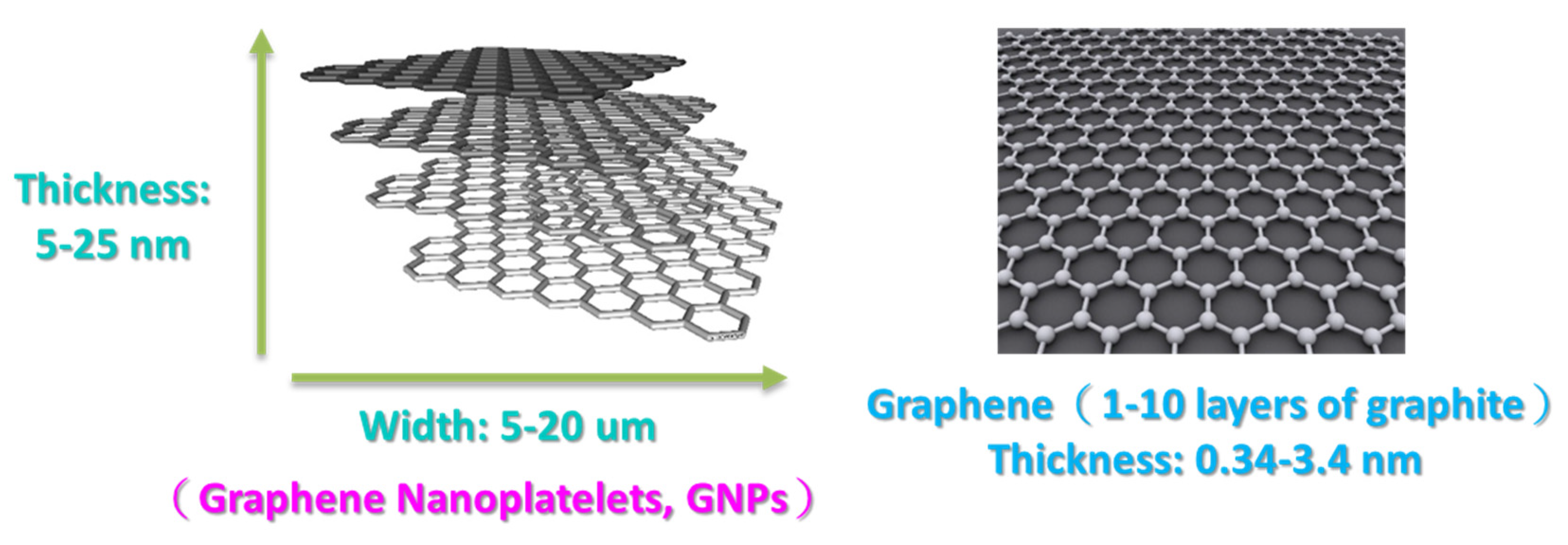
The arrangement of carbon atoms in graphene is the same as that in the single layer of graphite, which is a single layer of two-dimensional crystals composed of carbon atoms arranged in a honeycomb crystal lattice with sp2 mixed orbital domains. Graphene can be thought of as a lattice of atoms formed by carbon atoms and their covalent bonds. In general, a high specific surface area between a polymer and a nanoparticle maximizes the transfer of stress from the polymer matrix to the nanoparticle. This can effectively reduce the composite’s cracking caused by the stress concentration. Furthermore, 2D nano-carbon materials such as graphene have a higher specific surface area than multi-walled carbon nanotubes (MWCNTs) and are not as easily entangled and difficult to disperse as MWCNTs. Therefore, graphene would be a better reinforcement for polymer composites than carbon nanotubes (CNTs). Graphene nanoplatelets (GNPs) are ultrathin stacks of graphene layers with more than 10 carbon layers and thicknesses in the range of 5–100 nm. In some literature, they are also referred to as “graphene nanosheets” [2,3,4,5,6,7,8] (Figure 2). However, the large surface area of GNPs produces large van der Waals forces and strong π–π interactions between the planar nanosheets [9,10,11]. Thus, the applications of GNP-reinforced polymer nanocomposites are limited because of the bad dispersion result in the aggregation of GNP.
Epoxy resin is a molecule containing two or more epoxide functional groups. The process of mixing the resin and the hardener at a certain ratio after the chemical reaction to form a three-dimensional network structure (cross-linking) is called curing. In addition, epoxy resins are widely used in advanced carbon fiber-reinforced plastics (CFRPs) owing to their good mechanical performance, processibility, compatibility with most fibers, chemical resistance, wear resistance, and low cost [12,13]. However, the higher cross-link densities of epoxy resins can contribute to low absolute strength and poor fracture toughness, thereby limiting the use of epoxy composites in applications involving mechanical components [14]. Various types of reinforcements have been developed to improve the mechanical properties of epoxy-based composites [15,16,17,18]. Hence, nano-carbon materials, such as CNT or GNP, are usually used to improve the mechanical properties of polymer composites and their fiber-reinforced composite laminates (CFRP). However, nano-carbon materials are difficult to disperse into polymer matrices, resulting in the agglomeration in the polymer, and thus have limited properties and applications. This is because the van der Waals forces between the carbon nanomaterials can lead to agglomeration and, consequently, require the use of complex processes to obtain a homogeneous dispersal in a polymer matrix [18,19,20,21,22,23,24].
In our previous studies [19,22], we demonstrated that adding GNPs into epoxy matrices through traditional methods of dispersal (TD) and the subsequent preparation of GNP/epoxy nanocomposites and their CFRP laminates could improve the mechanical and interlaminar properties of the nanocomposite and CFRP laminates, respectively. However, the TD processing time required to prepare nanocomposites was high, although it significantly improved the mechanical properties. This is because the agglomeration arising from the van der Waals forces of nano-carbon materials resulted in a lengthy process time for the dispersion of these materials into the polymer matrices.
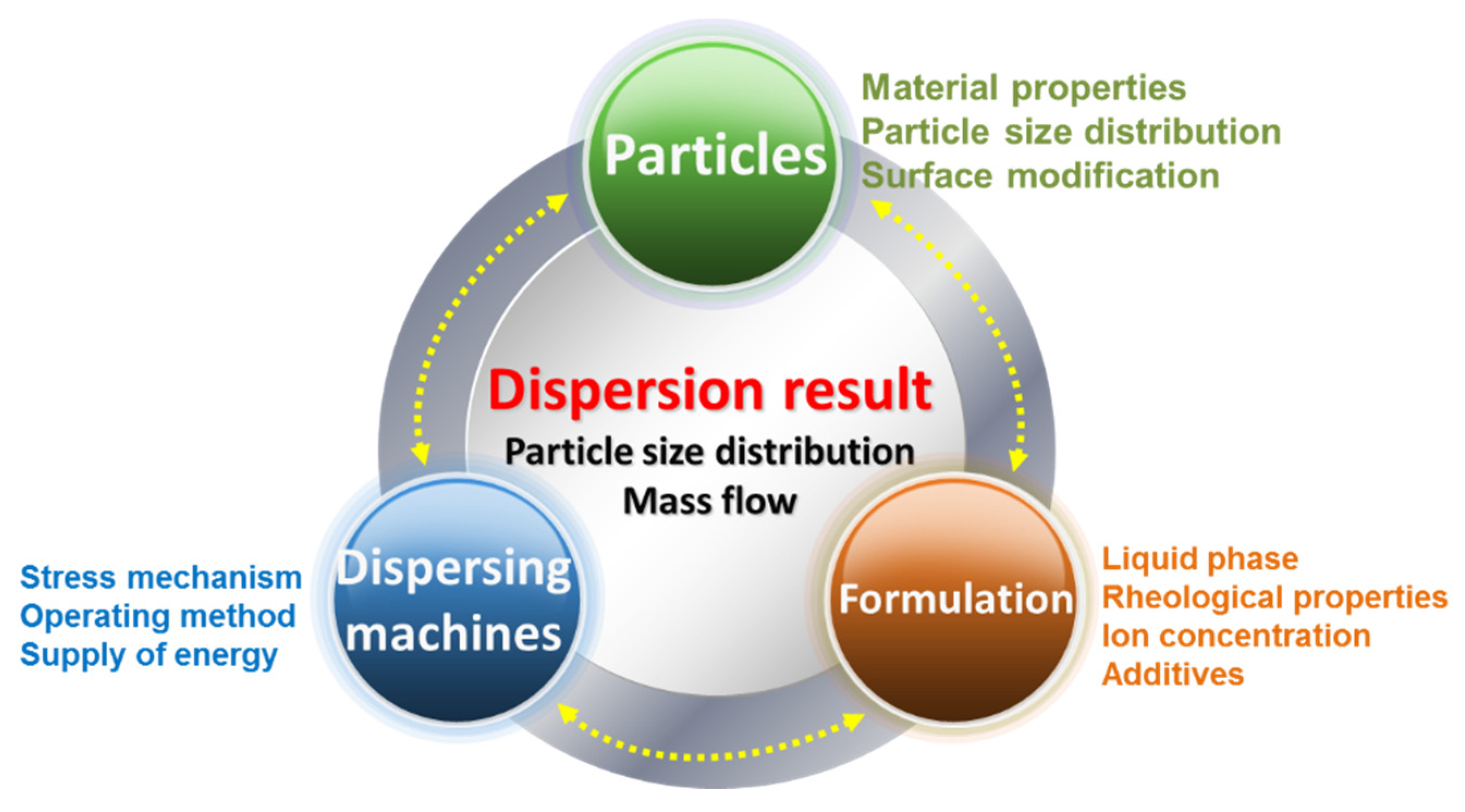
In general, the factors affecting the dispersal of nano-scaled particles can be divided into three interacting phases (Figure 3): the stress application mechanism, the operating method, and the specific energy supply are decided by the dispersal equipment. In contrast, the particle properties specify the resistance against the fragmentation of aggregates in the dispersal process. Basically, this includes the material properties, the surface modification, particle size distribution, and the particle–particle interactions (i.e., the surface modification of particles). For nano-particulate agglomerates and aggregates, particle–particle interactions are especially important and are very strong; they can be described according to the Derjaguin–Landau–Verwey–Overbeek theory [25,26]. The third key point is formulation, including the liquid phase of the nanoparticles, rheological properties, ion concentration, and additives.
The use of a three-roll milling apparatus has recently produced good results for nano-reinforcement dispersal. This method exerts shear forces over the particles and avoids the presence of compression forces. During three-roll milling, the adjacent rolls rotate in opposite directions, and the external shear forces generated in the gap between the rolls break large agglomerates into smaller aggregates and further into primary particles [27]. Thus, agglomerates can be separated without being damaged. In several studies [28,29,30,31,32,33,34,35], the three-roll milling process has proven to be an effective method for producing GNP/epoxy nanocomposites with a homogenous dispersion.
Planetary centrifugal mixing (PCM) has several advantages over other types of mixing using blade agitators [36,37]. The PCM apparatus utilizes centrifugal swirling, which causes less or no damage to materials that would be otherwise damaged by agitating blades. It can effectively de-aerate the mixture by means of large centrifugal forces and prevent contamination from outside, because the vial is perfectly sealed and no power-transmitting shafts need to pass into the interior of the vial. Consequently, PCM can be used for the rapid and homogeneous blending and dispersal of organic and inorganic powders, rheological fluids, and their mixtures, including, but not limited to, nano-and micro-sized powders [38,39,40,41,42,43,44], magnetic powders [45], and nano- and micro-particle suspensions [46,47].
Although the dispersal effectiveness has been established in the aforementioned studies and there are several dispersal processes for each type of nano-reinforcement/resin mixture, there is a lack of in-depth knowledge regarding the differences in the effectiveness of the dispersion attained. Furthermore, very few studies have been undertaken on the fabrication of nano-carbon materials, such as GNP-reinforced polymer nanocomposites, using different methods of dispersal with a subsequent investigation of their mechanical properties. Therefore, there remains a need to investigate the dispersal and the mechanical properties of GNP-reinforced epoxy resin.
In this study, two simple and efficient methods of dispersal (planetary centrifugal mixing (PCM) and three-roll milling (TRM)), were used to enable a uniform dispersal of GNP throughout an epoxy solution (i.e., 0, 0.1, 0.25, 0.5, and 1.0 wt.%), with the subsequent preparation of GNP/epoxy nanocomposites. The mechanical properties of the nanocomposites, including ultimate tensile strength, flexural strength, and flexural modulus, were investigated. To understand the differences between the traditional process of dispersal and these two dispersal processes, the results of our previous study [19] were compared to those of the current study.
Figure 2. Graphene and graphene nanoplatelets (GNPs) [48].
Sustainability 13 01788 g002
Figure 3. Factors affecting dispersal [26].
Sustainability 13 01788 g003

2. Materials and Methods

2.1. Nano-Carbon Materials

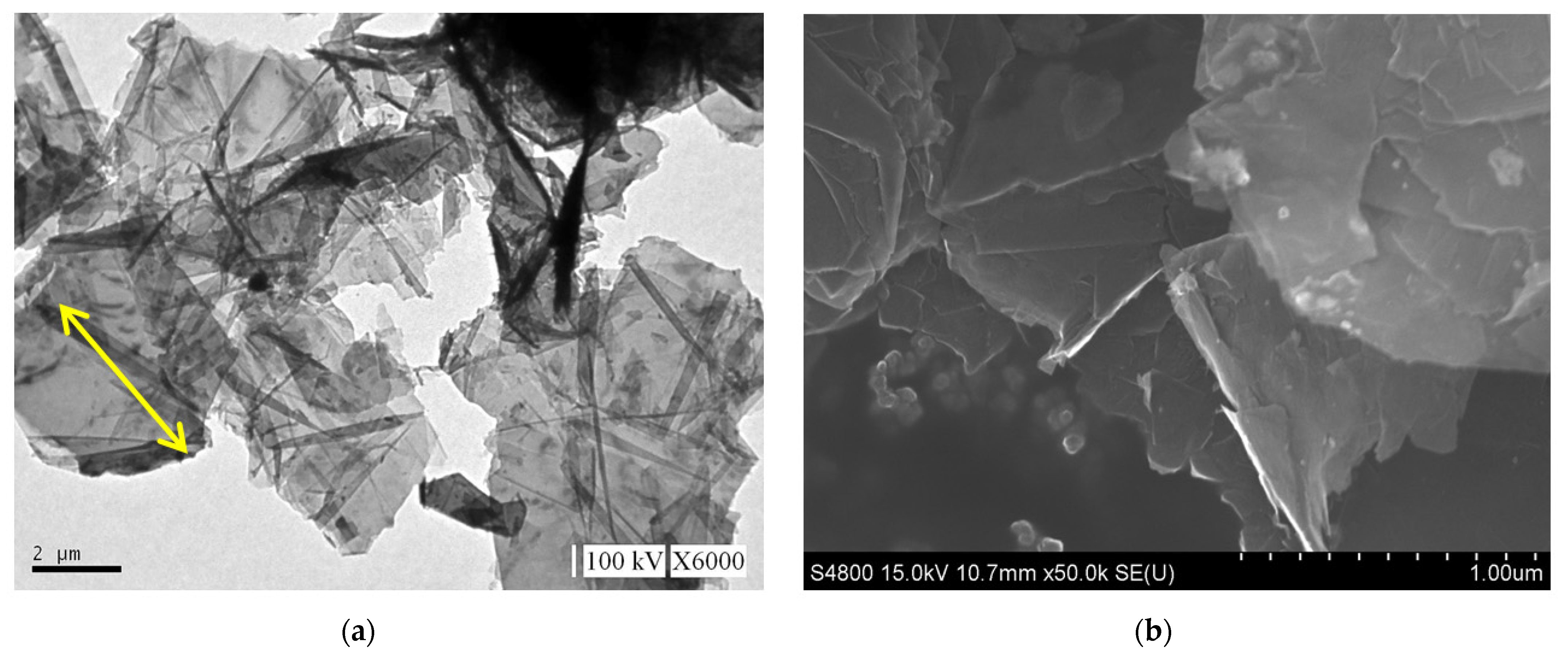
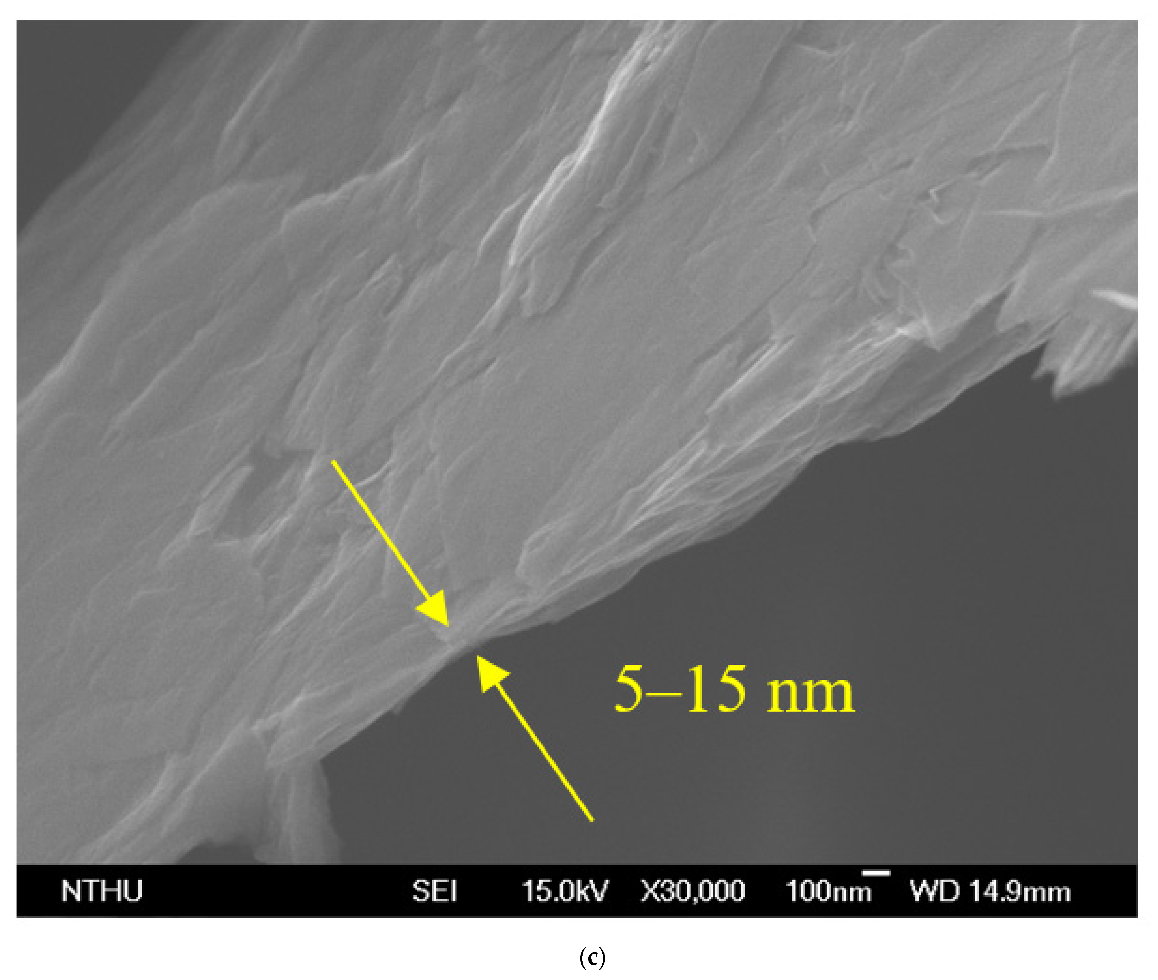
The GNP diameter was 3–5 μm, the thickness was approximately 5–25 nm, and the purity of the GNPs was >98%. Graphene is a single atomic layer of graphite with a thickness of 0.34 nm. In the industrial field, a single layer of graphite with less than 10 layers can be commonly referred to as “graphene”; the thickness of graphite can be several hundred microns. The nano-carbon material used in this study had a thickness of approximately 5–25 nm (within 100 layers), which was different from the structure of graphene and graphite. Therefore, this material was referred to as graphene nanoplatelets. The aspect ratio of GNP was approximately 30–60 m2/g, which enhanced the contact area with the polymer matrix. The theory bulk density of the GNP was 1.6 g/cm3. A transmission electron microscope (TEM) was used to determine the aspect ratio, and a field-emission scanning electron microscope (FESEM) was used to determine the thickness. The images obtained revealed that the surface morphology of GNP was considerably different to that of carbon black, CNTs, and graphite (Figure 4). The GNP particles were aggregated by van der Waals forces.
The carbon structure of carbon black differed from that of graphite and graphene or even GNPs in that it consisted of concentrically aligned vortex layers of graphite domains. This structure was proposed by Heidenreich et al. in 1968 [49], as shown in Figure 5.

2.2. Preparation of GNP/Epoxy Resin Nanocomposites

Two GNP/epoxy solutions were prepared using two different mixing techniques. One was a planetary centrifugal mixer (Mazerustar KK-250S; Kurabo Industries Ltd., Osaka, Japan), and the other was a three-roll miller (RY-R065; Renyih Industrial Co., Ltd., Taiwan).

2.2.1. Preparation of GNP/Epoxy Resin Solution Using Planetary Centrifugal Mixing

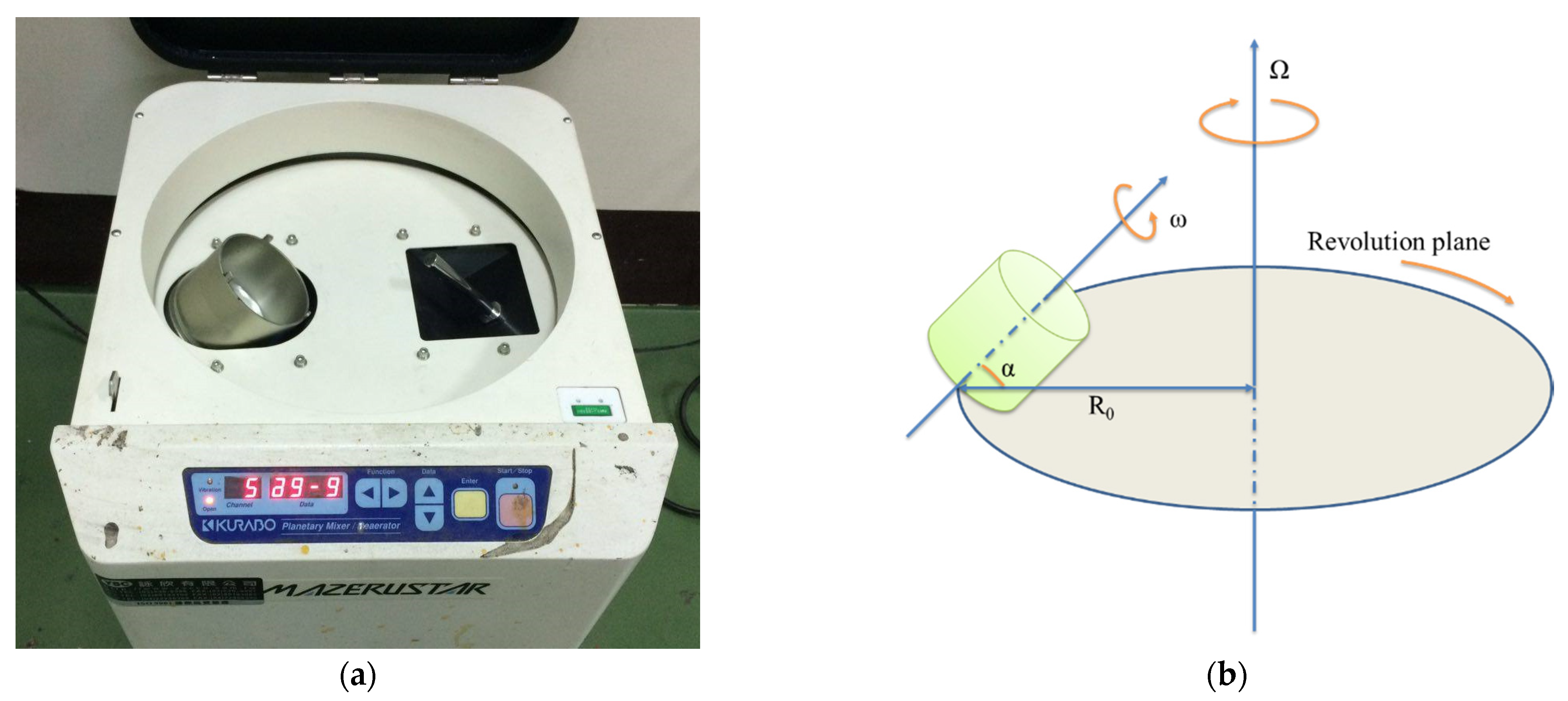
The GNPs obtained from Xiamen Knano Graphene Technology Co., Ltd., China, were first dried at 120 °C for 120 min in order to eliminate the moisture within them. A methyl ethyl ketone (MEK) solvent was mixed with GNP and then vibrated by ultrasonication for 30 min to enable a homogeneous GNP dispersion. A solvent-type epoxy resin (EPO-622TM obtained from Epotech Composite Co., Ltd., Taiwan) was then added into the MEK/GNP solution, and the mixture was stirred for 20 min by using a planetary centrifugal mixing apparatus to enable the MEK/GNP to disperse uniformly throughout the epoxy resin. This mixer used a mechanism whereby the container holding the material revolved clockwise while the container itself rotated counter-clockwise (rotation). Finally, the MEK/GNP/epoxy solution was placed in an oven at 83 °C to evaporate the solvent (MEK). A schematic representation of the fabrication of the GNP/epoxy solution by PCM is shown in Figure 6a.
The planetary centrifugal mixing machine consisted of a cylindrical container that generally had a flat bottom with no obstacles or agitators. The container was subject to two rotational movements: one was rotation around its geometric axis, and the other was a revolution around an axis located at a given distance (R0). Figure 7 presents a schematic representation of this instrument, which approximated the shape and the function of a standard centrifuge. The difference from a centrifuge was that a plastic container was also rotated at an appropriate speed. The mixing container rotated in the opposite direction to the central rotating shaft at speed, as well as the central rotating drum, thus generating high shear forces in the container. This combination homogenized the nanoparticle in the epoxy matrix. Using this mixer, the sub-micrometer-sized (diameter) GNP particles could be dispersed homogeneously into the resin within 20 min, which was a shorter treatment time than that obtained in our previous studies [19,22].

2.2.2. Preparation of GNP/Epoxy Resin Solution by Three-Roll Milling (TRM)

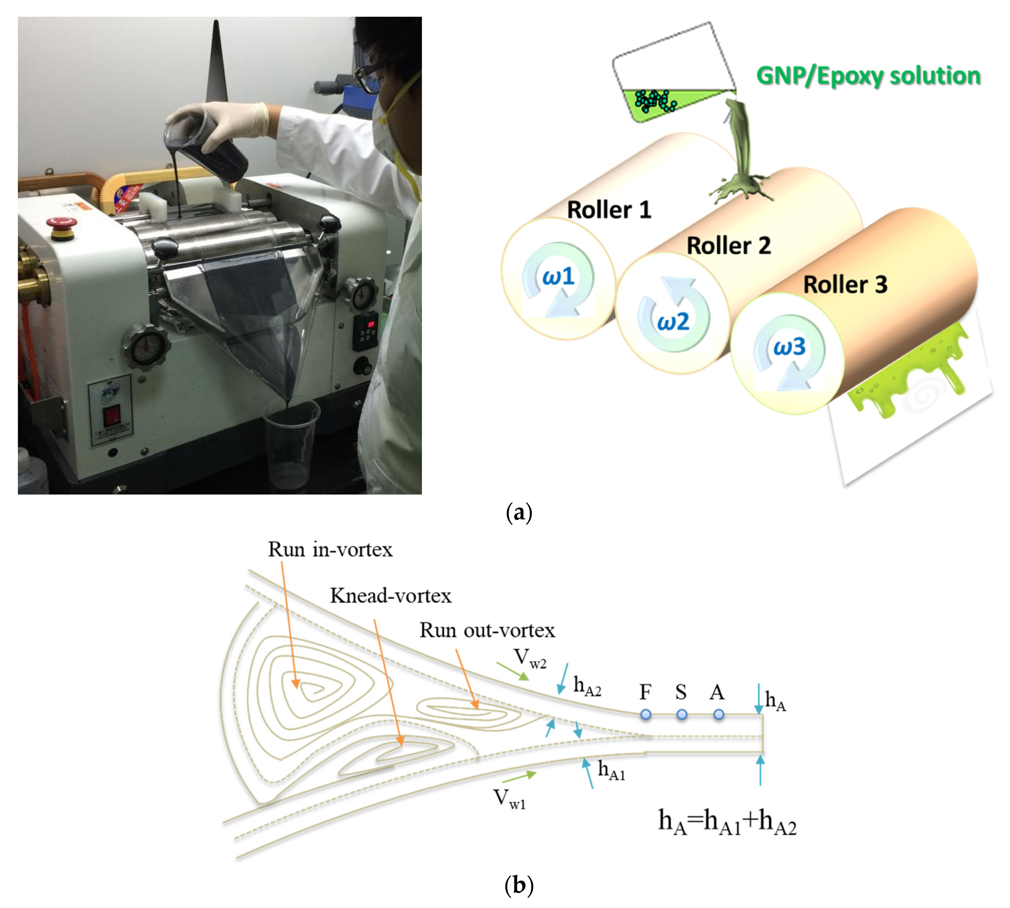
The GNPs were dried in an oven at 120 °C for 120 min to eliminate the moisture within them. They were subsequently mixed with epoxy resin for 30 min by using a mechanical mixer and then mixed using a three-roll milling apparatus for 100 min to improve the uniformity of the GNP distribution in the epoxy solution. The gap size between each pair of rolls varied as a function of the steps (in microns): (1) 320–340; (2) 260–290; (3) 210–230; (4) 160–180; and (5) 110–130. The dispersion time of one gap was 20 min, and the total time of all the five gaps was 100 min. During the three-roll milling process, rollers 1 and 3 rotated in the same direction, whereas roller 2, located between 1 and 3, rotated in the opposite direction, thereby inducing high shearing in the mixture. The three rollers rotated at different speeds, with the speed ratio among them maintained at 9:3:1 (ω3 = 3ω2 = 9ω1) in each of the three passes. The mismatch between the angular velocity of the adjacent rolls and the direction of rotation (clockwise or anticlockwise) was controlled to exert high shear forces over the mixture (Figure 8a). The mixture was poured between the two first rolls and was collected after the third roll. The separation between the rolls influenced the forces exerted over the mixture and therefore on the dispersion achieved. Smaller distances between the rolls produced greater shear forces, which were necessary to break large agglomerates. The reduction of the agglomeration size resulted in a better dispersion of the nano-reinforcement. Nevertheless, when the force exerted was too large, it might break the structure of GNPs, leading to a reduced aspect ratio of the GNPs. The principle of the flow conditions can be seen in Figure 8b [50]. A primary dispersion of the agglomerates could be achieved by the knead-vortex between the rolls, while the final exfoliation and dispersion of the GNPs occurred in the area between the rolls. During the dispersion process, the adjacent rollers rotated at different speeds and in opposite directions. The dispersion effect resulted from the high shear stresses generated in the gap between the rolls. A schematic representation of the fabrication of the GNP/epoxy solution by the three-roll milling process is shown in Figure 6b.

2.2.3. Preparation of GNP/Epoxy Nanocomposites

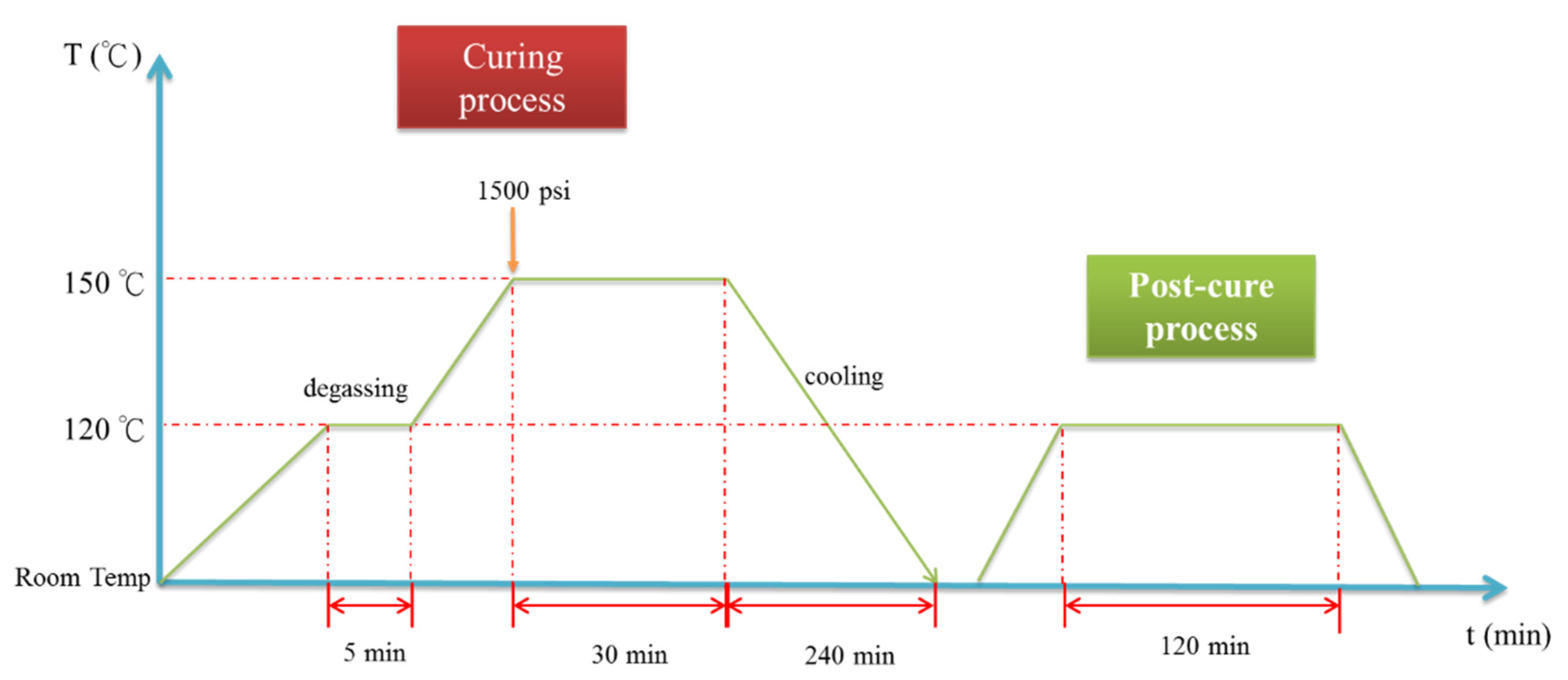
The GNP/epoxy resin solution (dispersed through one of two processes) was first placed in a vacuum heating oven to eliminate air bubbles and residual solvents. The resin solution was then poured into molds and placed on a hot-press machine to prepare the GNP/epoxy nanocomposites. A schematic representation of the fabrication of the GNP/epoxy nanocomposite is shown in Figure 6c. The curing cycle of the nanocomposite is shown in Figure 9. Note that the temperature of the epoxy solution was raised from room temperature to 120 °C and held for 5 min to increase the flow of the resin as well as to allow the degassing from the mold. The temperature was then raised to 150 °C; the resin started to enter curing, and the pressurization process started at this time. In this period, the perfect composite could be prepared under the effect both temperature and pressure. After holding the temperature for 30 min, the composite started to cool; it took approximately 240 min for the composite to cool from 150 °C to room temperature. Finally, the nanocomposite could be demolded. After the preparation of the nanocomposites was completed, the nanocomposites were placed in a heating oven at 120 °C for 120 min to eliminate the internal stress; this was called the “post-curing” process.

2.3. Test Methods

2.3.1. Tensile Test

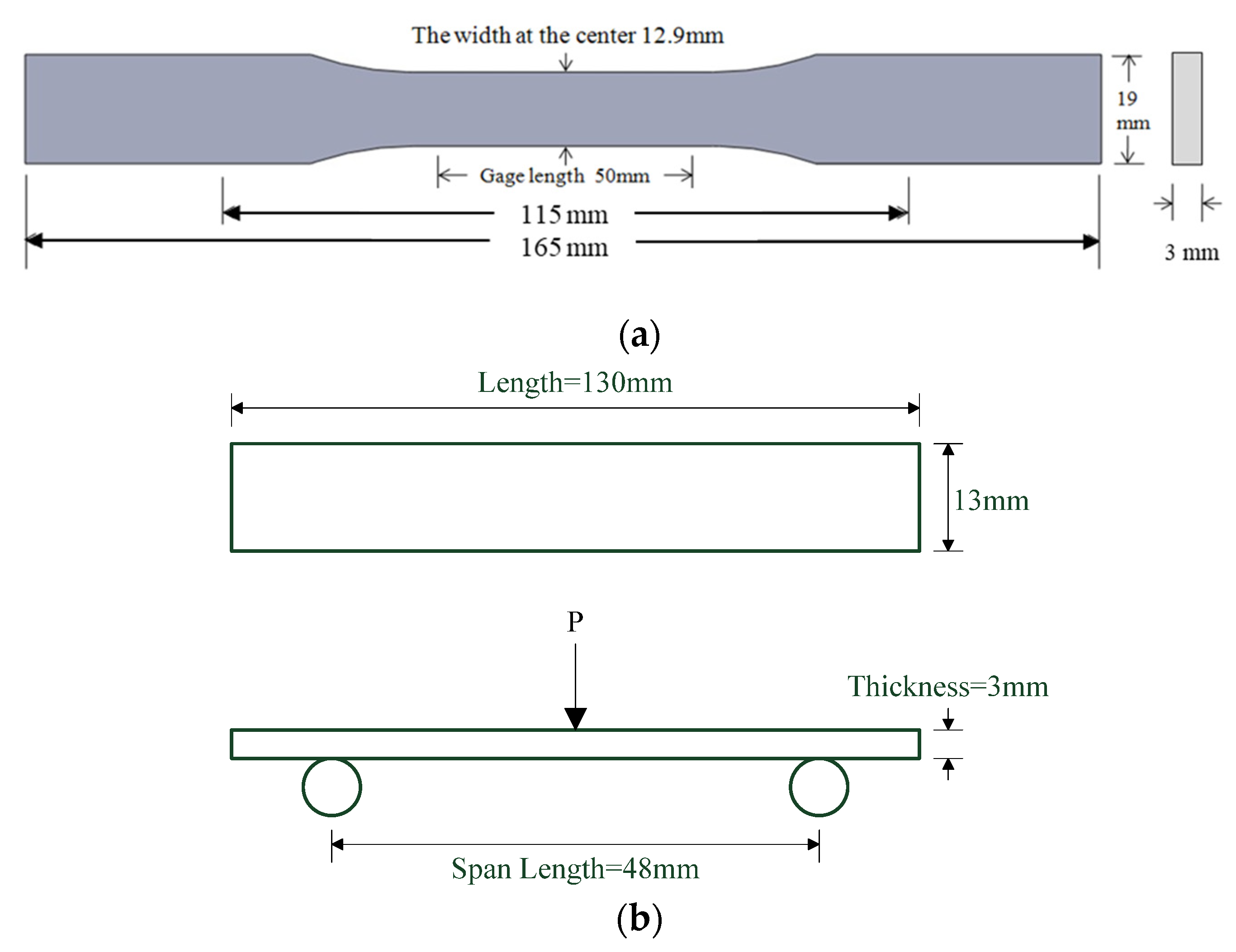
The tensile strength of GNP/epoxy nanocomposites was measured using a universal materials testing system (Instron 3369). The tensile testing specimens with a dumb-bell shape were prepared by machining samples from 3-mm-thick plates; the samples had a gauge length of 50 mm, according to ASTM D 638 type I. An extensometer with a 50-mm gauge length was used for measuring the axial strain and was stuck on the surfaces. During the tests, the specimens were subjected to tensile loading at a crosshead speed of 1 mm min−1 at room temperature. The dimensions of the tensile specimen are shown in Figure 10a. Five specimens of each nanocomposite were taken and tested for the ultimate tensile strength σ t , which was obtained from the average value as follows:
σ t = P A
where P is the maximum tension loading (N) and A is the section area.

2.3.2. Flexural Test

The flexural properties were determined according ASTM D790-17 by using the three-point bending test method. The dimension of the rectangular flexural specimen was 130 mm × 13 mm × 3 mm, and the span was 16 times the thickness according to the standard, i.e., 48 mm. As the thickness of the specimen varied slightly because of the preparation process, the average thickness of the specimen was used as the span setting value before each test, and then the span and drop rate were calculated according to this value. The bending test value was obtained by averaging the test data. The maximum loads were obtained and the flexural strength (σf) and modulus (EB) were calculated using the following formulas respectively; the data were obtained from the average of the five tested values. The dimensions of flexural specimen are shown in Figure 10b.
σ f = 3 P L 2 W t 2 E B = L 3 m 4 W t 3
where P is the maximum load (N); L is the span, which is the distance between the supports (mm); m is the initial slope of the linear region of the load/displacement curve; W is the width of the specimen (mm); and t is the thickness (mm).

2.3.3. Viscosity Test

In this study, the kinetic viscosity was calculated according to the kinematic viscosity measurement described in the ASTMD445 standard: η in the fluid with two areas of 1 m2, 1 m apart, and a relative speed of movement of 1 m/s; the resistance thus faced is called kinetic viscosity. The unit of kinetic viscosity is pascal-seconds. The kinetic viscosity η was calculated by using the following formula:
η = ρυ
where η is the kinetic viscosity; ρ is the density of the fluid, and υ is the kinematic viscosity.

3. Results and Discussion

3.1. Mechanical Properties of GNP/Epoxy Nanocomposites Prepared Using Planetary Centrifugal Mixing

The planetary centrifugal mixing equipment used in this study enables simultaneous mixing/de-aerating within a short time without the use of mixing rods and blades. In order to find the best planetary centrifugal mixing condition, two different parameters were used to disperse GNPs into epoxy, followed by an investigation of the mechanical properties of the GNP/epoxy nanocomposite.
Table 1 summarizes the different dispersal parameters of the PCM used in this study. The rate of revolution could be varied between approximately 640 and 1700 rpm, with 10 increments. The rate of rotation also had 10 increments and ranged between 0.0 and 1.0 times the speed of revolution. The revolution speed of level 10 was approximately 1700 rpm. The revolution and the rotation speed of Channel 1 (CH 1) was approximately 1200 rpm and approximately 500 rpm, respectively. The equivalent values for CH 2 were approximately 1600 and 1600 rpm, respectively. CH 1 is predominantly used for stand mixing and de-aerating, and CH 2 is focused on mixing. In this study, these two different mixing channels were used to investigate the efficiency of GNP dispersal into the epoxy resin because the impact of de-aeration on the dispersal of GNPs into the epoxy was not known.
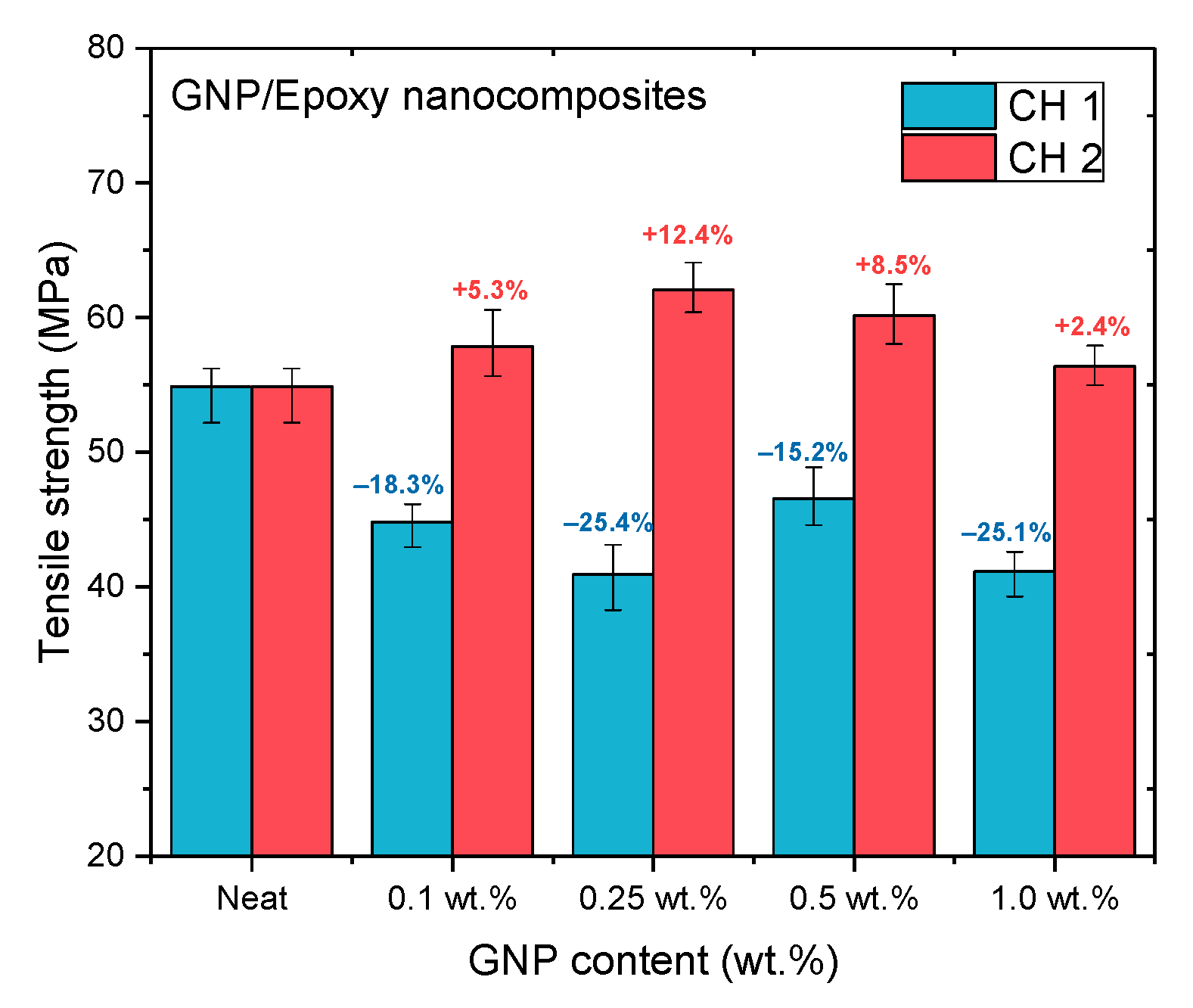
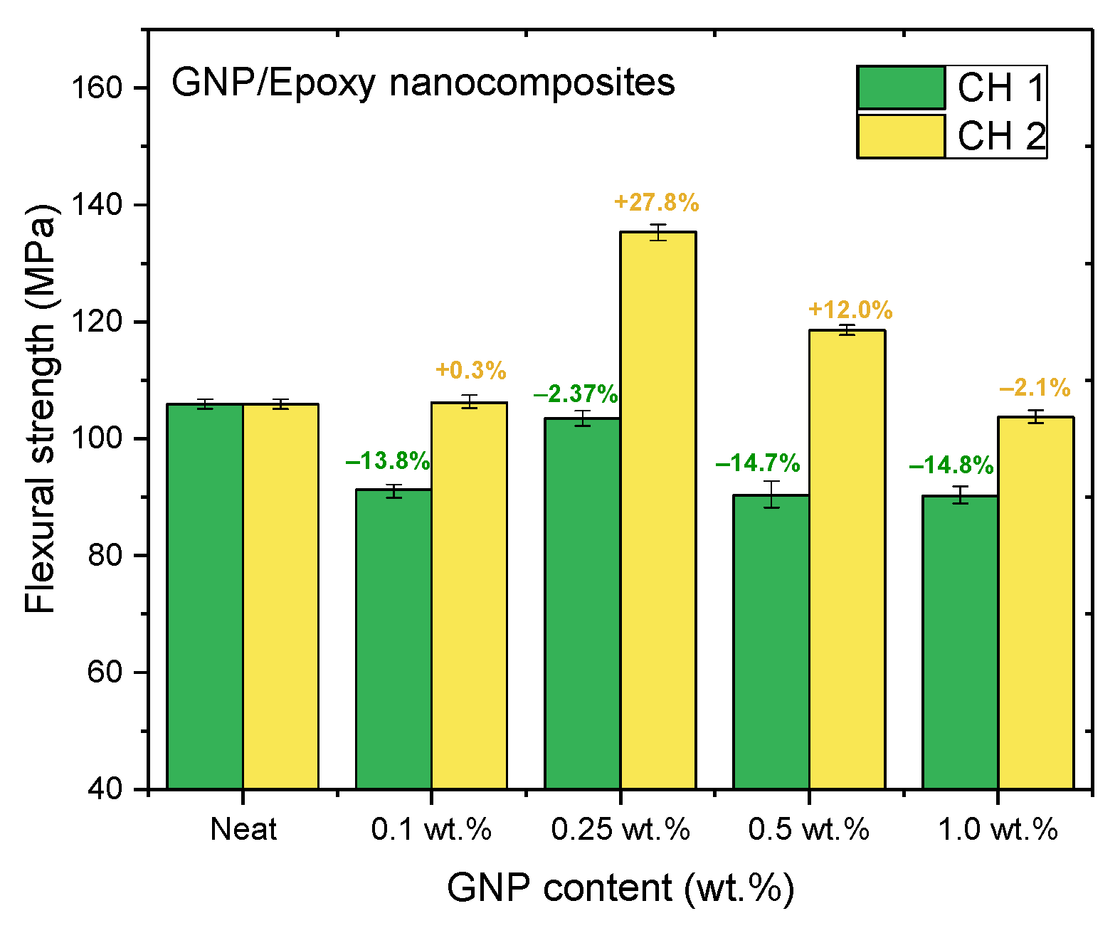
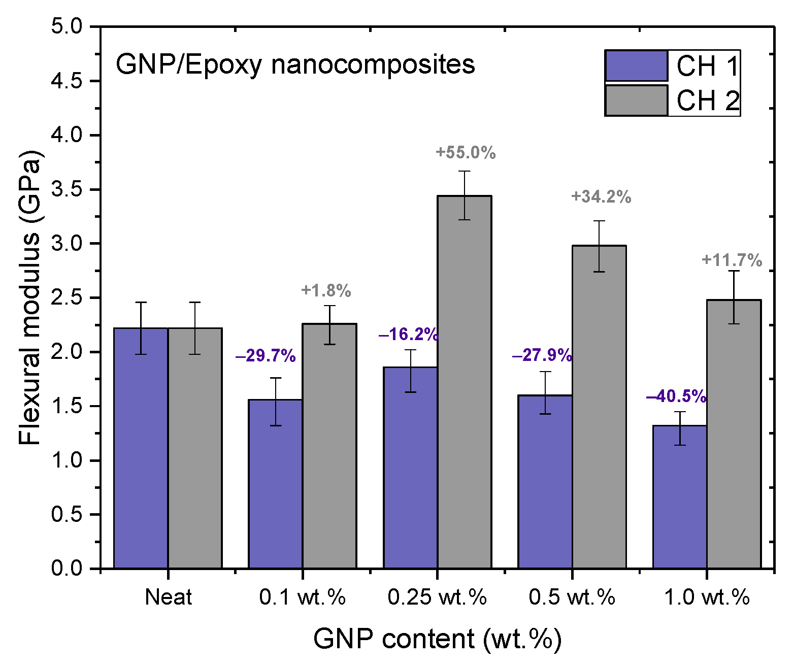
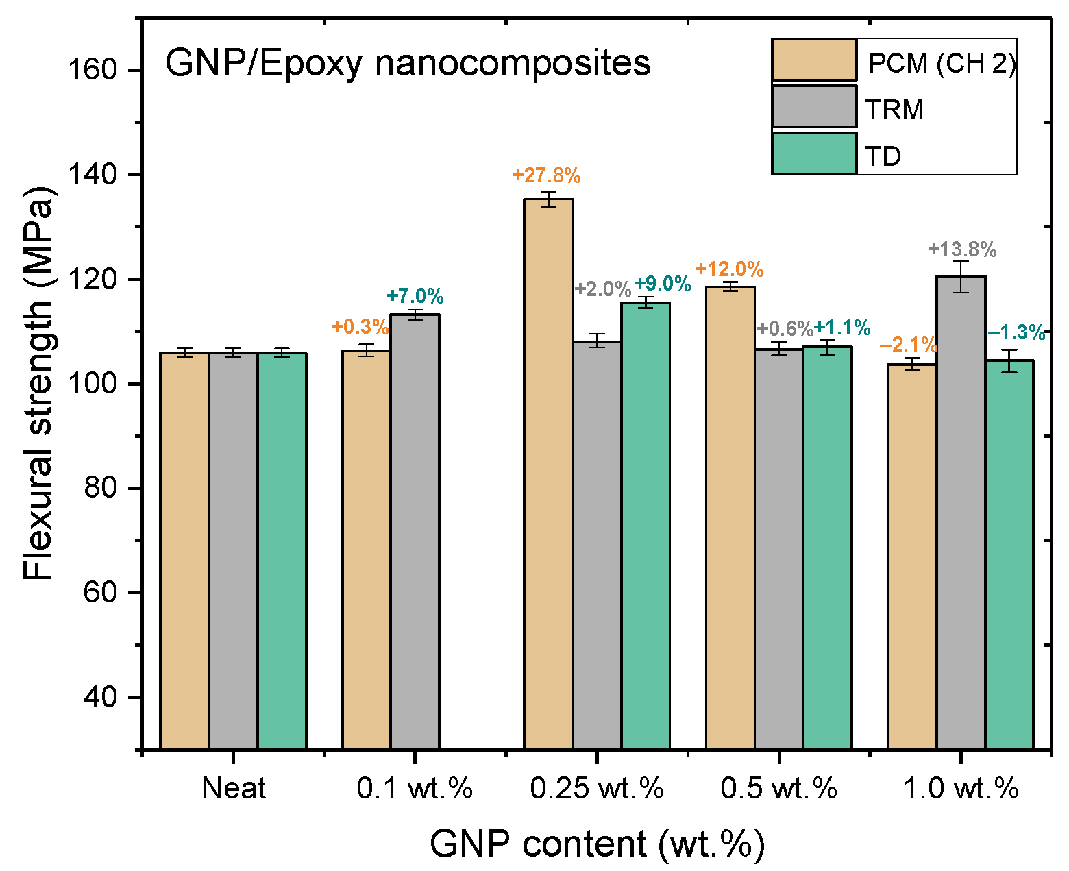
Figure 11, Figure 12 and Figure 13 and Table 2 show the ultimate tensile strengths, flexural strengths, and flexural moduli of the epoxy nanocomposites with different contents of GNPs. The epoxy resin containing GNPs prepared with either channel of the PCM exhibited different mechanical properties as compared to the pure resin. The dispersion experienced with CH 1 emphasized standard dispersion (including mixing, degassing, and temperature suppression), which differed from CH 2′s emphasis on mixing. Therefore, when GNPs were mixed with the epoxy resin, the poor dispersion resulted in the poor mechanical properties of the nanocomposites.
When GNPs were combined with epoxy through the CH 2 dispersal, the mechanical properties of the nanocomposite with GNPs added at 0.25 wt.% exhibited the best enhancement, as compared to the neat epoxy resin without any GNPs added. In our previous study [19], the GNPs were used to reinforce the epoxy composite to enhance their mechanical properties using the traditional dispersal (TD) process. This earlier study also demonstrated that when GNPs were added at 0.25 wt.%, the mechanical properties of nanocomposites were enhanced the most. To investigate the effect of different dispersal mechanisms on the mechanical properties of epoxy nanocomposites reinforced with GNP, CH 2 was used in this study to prepare a GNP/epoxy nanocomposite; this was compared with the results obtained using other mixing processes.

3.2. Mechanical Properties of GNP/Epoxy Nanocomposites Prepared Using Different Methods of Dispersal

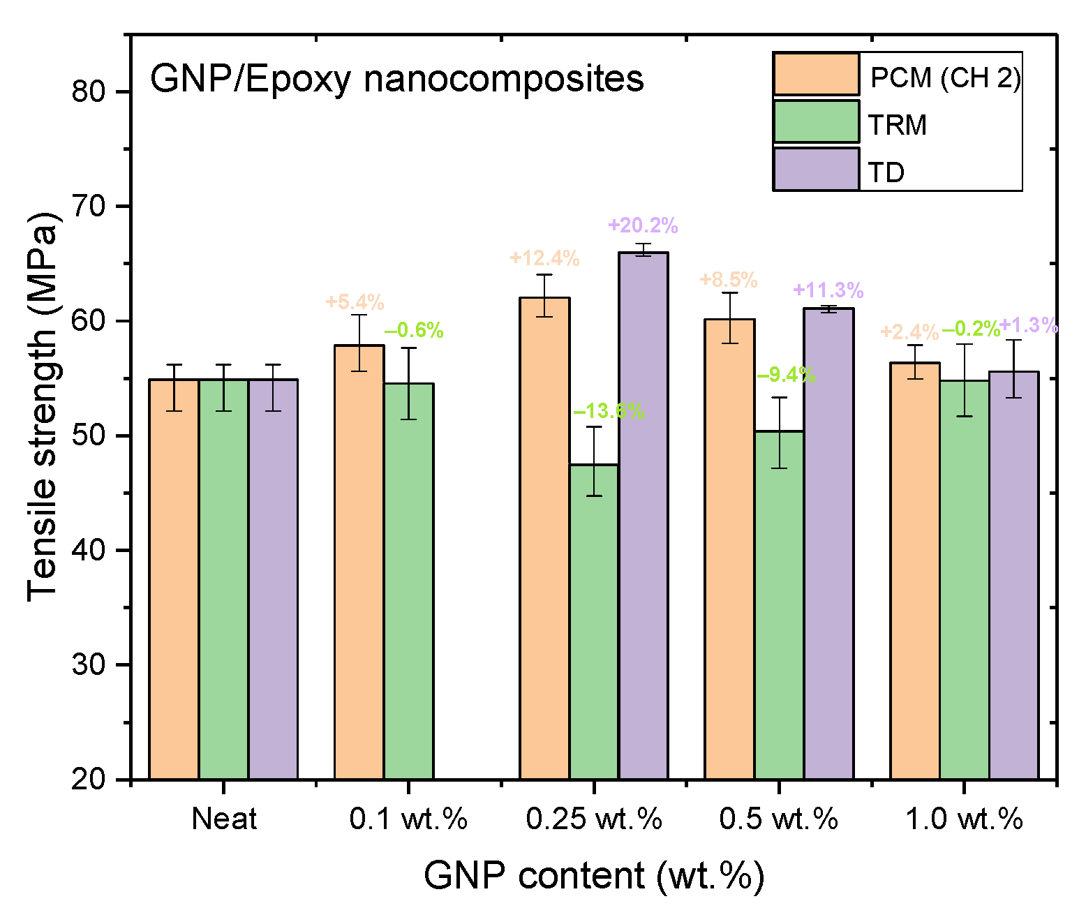
Figure 14, Figure 15 and Figure 16 and Table 3, Table 4, Table 5 show the tensile strengths, flexural strengths, and flexural moduli of the epoxy nanocomposites fabricated with different GNP contents, using three dispersing processes. The mechanical properties of the nanocomposites prepared using PCM and TRM were investigated in this study, and the data pertaining to the traditional dispersal (TD) was taken from our previous study [22].
Nanocomposites prepared using PCM exhibited the same reinforcement effect as that observed with TD, and both exhibited better mechanical properties than pure resin. In our previous study, the use of TD to prepare nanocomposites demonstrated that the mechanical properties of GNP/epoxy nanocomposites were optimal when 0.25 wt.% GNP was added. These results were similar to those obtained using PCM. Furthermore, Figure 15 and Figure 16 indicate that the flexural strengths and the flexural moduli of the nanocomposites without the added GNPs were approximately 105.89 MPa and 2.22 GPa, respectively. The reinforced nanocomposite containing 0.25 wt.% GNP, generated using PCM, exhibited very significantly improved flexural strength (27.8%) and flexural modulus (55.5%) compared to the neat epoxy resin.
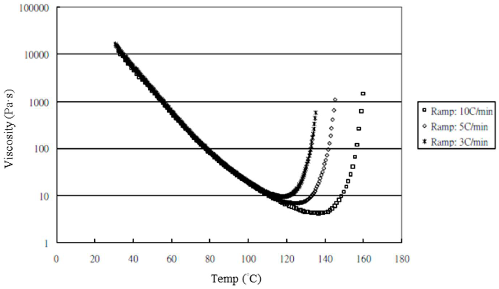
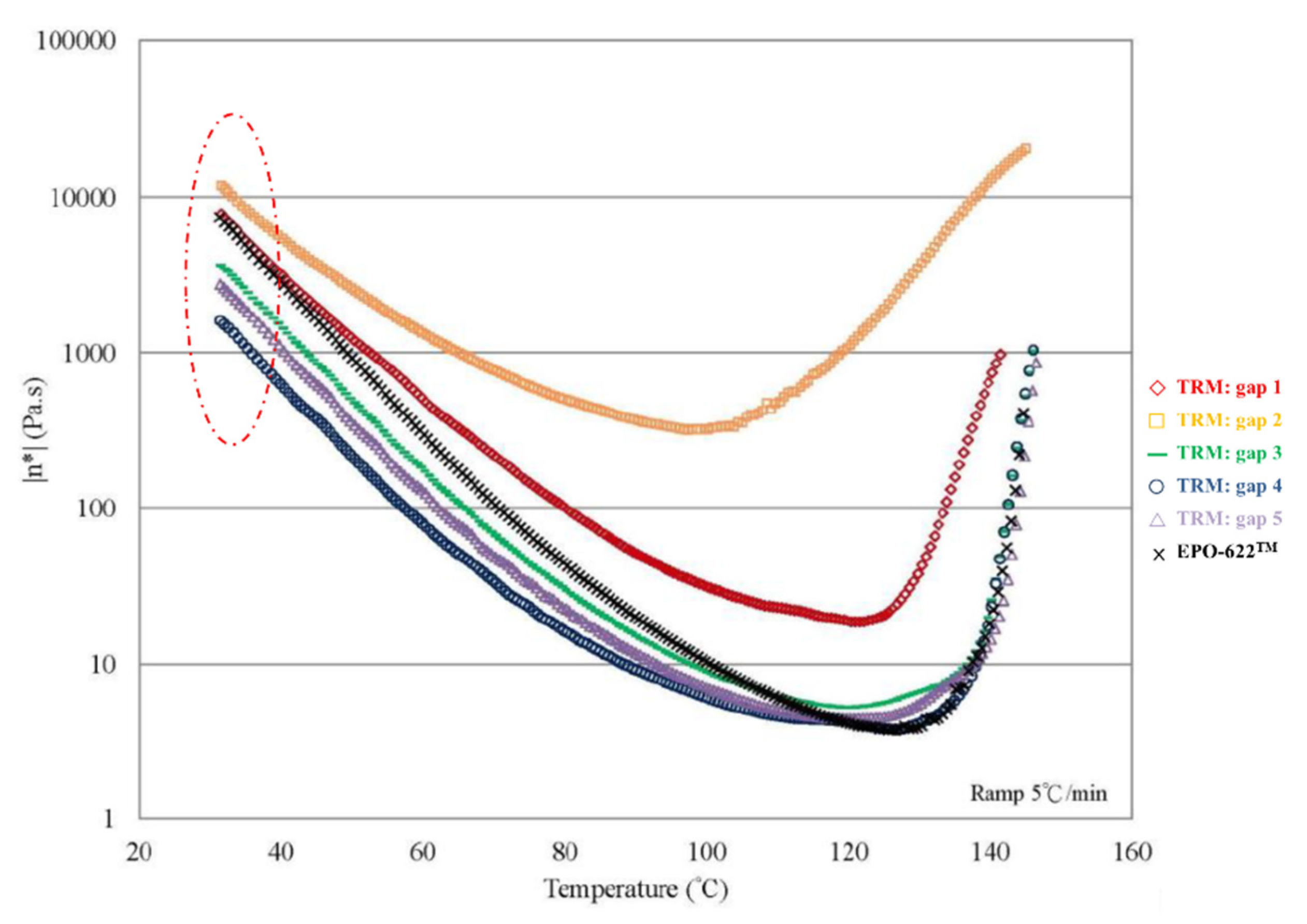
The nanocomposites showed very significant mechanical enhancement by PCM and TD; Table 6 compares the different durations of dispersal with GNPs mixed into epoxy. For the TD process, although significant improvements in the mechanical properties (from 0.25–1 wt.%) were apparent, the time required for processing was reasonably long (a total of 190 min). In contrast, the TRM processing time was shorter than that required in the TD process. The epoxy resin used in this study was a solvent-type (low-viscosity) resin, and the open operating space resulted in solvent evaporation, thereby causing a variation in the viscosity within the different gaps applied by the TRM process (Figure 8a). Resin viscosity was the key factor in the dispersal of nanomaterials into the resin. To ensure that GNPs could be effectively dispersed into the epoxy resin by three-roll milling, the solvent (MEK) had to be irregularly added to reduce the variability in the viscosity of the resin during TRM. Consequently, the viscosity of the resin changed irregularly during TRM. The viscosities of EPO-622TM and GNP/epoxy (TRM) at 30 °C are presented in Figure 17 and Figure 18 and Table 7. The viscosity of the GNP/epoxy resin produced by TRM exhibited significant changes, which resulted in the instability and non-uniformity of the dispersal of GNPs into epoxy resin and in turn the instability of the mechanical properties of nanocomposites.
The high speed and shorter processing time for dispersal required by PCM aided in maintaining stability and resulted in a significant improvement of the mechanical properties of nanocomposites. This was because of the high shear strength imposed in a close dispersing space. The mechanism of rotation in PCM was similar to the vortex fluidic exfoliation process [51]. The aggregation and stacking between GNP particles arose because of the van der Waals forces. In the PCM device, the high internal shear stresses within the tube wall provided the necessary conditions for dispersal. According to fluid dynamics, the liquid flow was upwards at the internal surface of the rotating tube, and downwards close to the liquid surface (Stewartson/Ekman layers) (Figure 19a). The shear layers were parallel to the axis of rotation in the rapidly rotating fluid, and the GNP particles initially accelerated to the walls of the tube because of the large centrifugal force.
In the rapidly rotating fluid, the shear layers were parallel to the axis of rotation. The large centrifugal force initially accelerated the GNPs to the walls of the tube, as shown in Figure 19b,c; the GNP particle exfoliation occurred via this rotation process. This required the lifting of individual particles from the surface of the bulk GNP, arising through the presence of a lateral force. The exfoliation involved a slippage process, whereby the GNPs were displaced relative to each other. Therefore, a large centrifugal force ensured that the GNPs experienced a shear-induced displacement along the surface.
Planetary centrifugal mixing simultaneously combined rotation and revolution. A powerful centrifugal force enabled the materials to be well dispersed. Rotation could effectively exfoliate GNPs, while revolution could further disperse GNPs into the resin and complete the de-aeration. Thus, CH 2, with a processing time of 20 min, was found to be the optimal setting for dispersing GNPs into epoxy resin in this study.

3.3. Morphology of GNP/Epoxy Nanocomposites

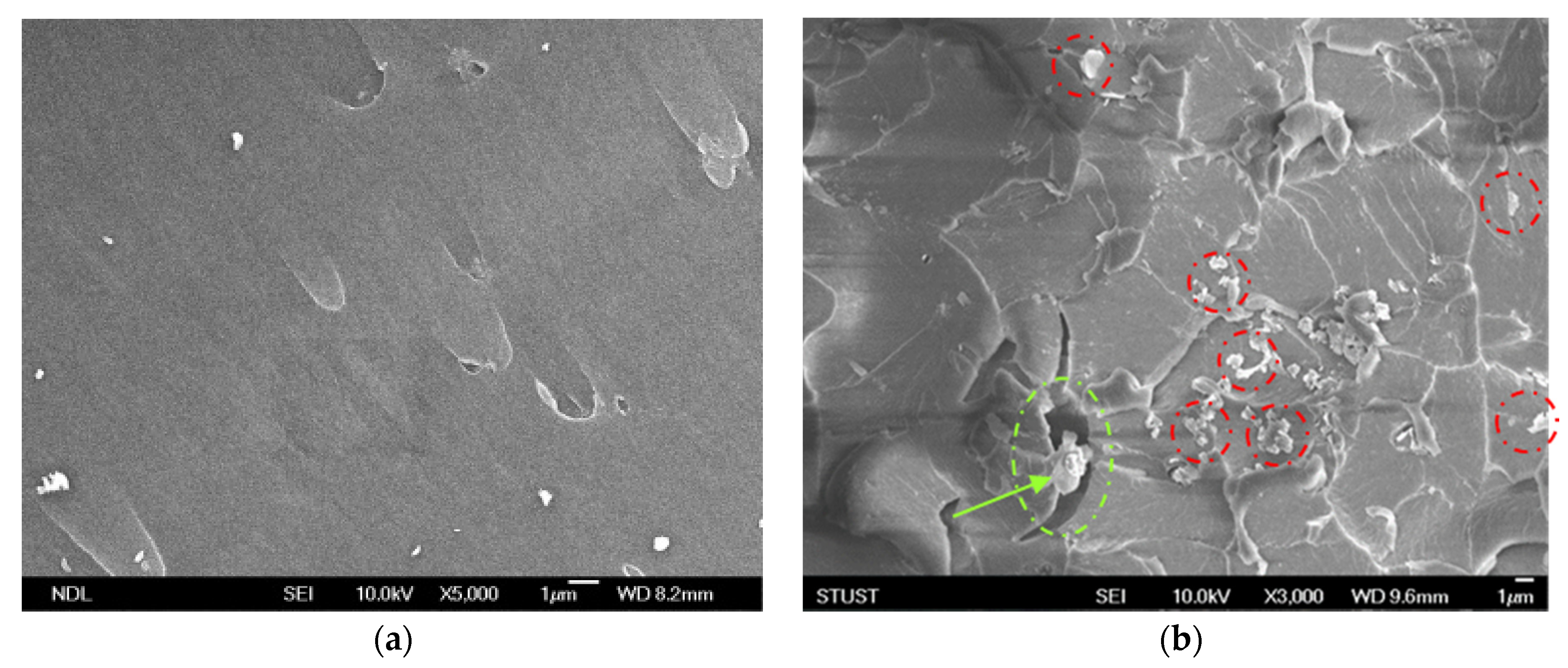
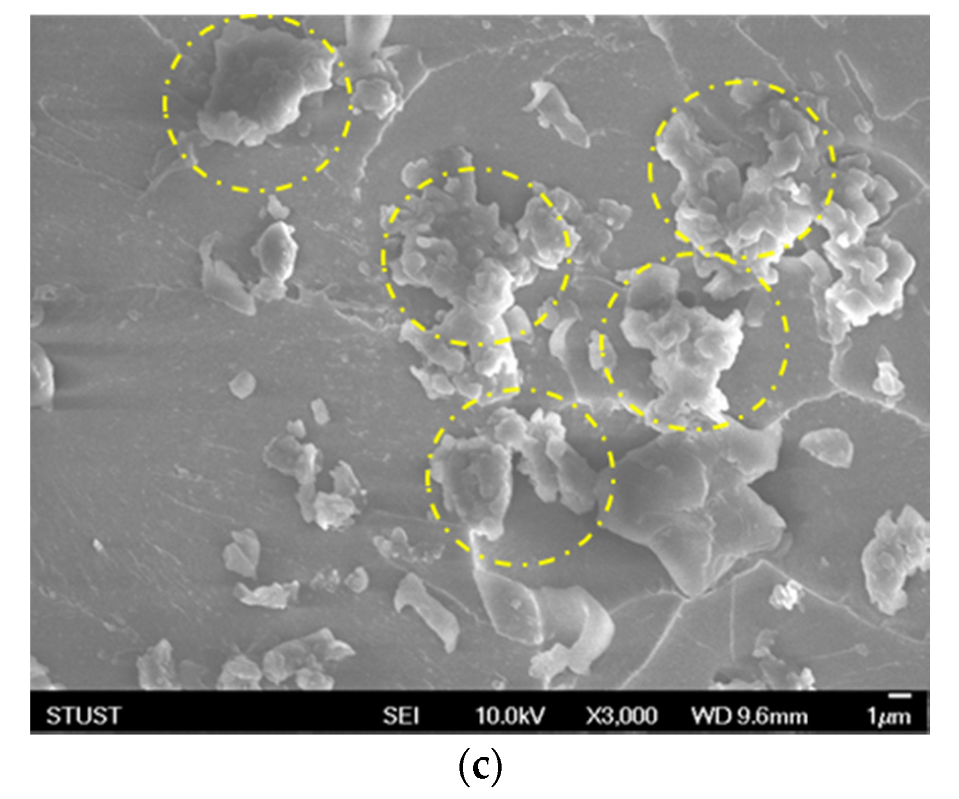
In order to confirm the dispersal mechanism of the GNP-reinforced epoxy nanocomposite under two different dispersing processes, the FESEM was used to identify the fracture surface of the nanocomposite added with 0.25-wt.% GNPs. Figure 20a shows an scanning electron microscope (SEM) image of a neat cured-epoxy resin without GNP added; here, it can be seen that the breaking surface of the resin was quite smooth. Figure 20b,c show the broken section of the GNP/epoxy nanocomposite with the 0.25-wt.% GNP addition after the tensile test. With the same amount of GNP added, the average particle size of GNPs was smaller and the distribution in the resin was more uniform for the PCM dispersal process. This indicated that the shear force of the PCM method was stronger and could effectively overcome the van der Waals force between the particles, resulting in a better dispersion effect. Moreover, when the GNPs had good dispersion, the GNPs located in the crevices in the corrugation area restrained the crevice growth. Therefore, the mechanical properties of the nanocomposite could be significantly improved.

4. Conclusions

All the three methods of dispersal improved the mechanical properties of the GNP/epoxy nanocomposites. For the TD process, the poor efficiency arose from the longer processing time. Although TRM improved the mechanical properties of the nanocomposites, the variable viscosity of the GNP/epoxy solution during the dispersal resulted in the unstable mechanical properties of the nanocomposites.
The morphological analysis by SEM revealed that the average particle size of the GNPs dispersed by the PCM method was not only smaller but also more uniformly dispersed around the resin, which was the key reason for the better mechanical properties. Therefore, the dispersion of GNPs into epoxy resin by the PCM method was not only efficient in terms of the process time but also significantly improved the mechanical properties of the nanocomposites. PCM could thus be deemed a more efficient and economically viable method of dispersal for the preparation of epoxy-based nanocomposites.

Author Contributions

Conceptualization, M.-Y.S.; methodology, M.-Y.S.; validation, W.-Y.L.; formal analysis, T.-Q.W.; investigation, M.-Y.S., W.-Y.L. and T.-Q.W.; resources, M.-Y.S.; data curation, W.-M.L.; writing—original draft preparation, M.-Y.S.; visualization, M.-Y.S.; supervision, M.-Y.S.; project administration, M.-Y.S.; funding acquisition, M.-Y.S. All authors have read and agreed to the published version of the manuscript.

Funding

This study is supported by the Ministry of Science and Technology (MOST) of Taiwan to National Chin-Yi University of Technology under a Contract No. MOST 107-2221-E-167-030-MY2.

Institutional Review Board Statement

Not applicable.

Informed Consent Statement

Not applicable.

Data Availability Statement

Not applicable.

Acknowledgments

This study was supported by the Ministry of Science and Technology (MOST) of Taiwan to National Chin-Yi University of Technology under MOST 107-2221-E-167-030-MY2. The authors also thank the Department of Biomechatronic Engineering, National Chiayi University, Taiwan, for guidance on analysis principles, and Epotech Composite Co., Ltd., Taiwan, who help with resin viscosity analysis was invaluable.

Conflicts of Interest

The authors declare no conflict of interest.

References

  1. Sharma, V.K.; McDonald, T.J.; Kim, H.; Garg, V.K. Magnetic graphene-carbon nanotube iron nanocomposites as adsorbents and antibacterial agents for water purification. Adv. Colloid Interface Sci. 2015, 225, 229–240. [Google Scholar] [CrossRef]
  2. Li, J.; Kim, J.K. Percolation threshold of conducting polymer composites containing 3D randomly distributed graphite nanoplatelets. Compos. Sci. Technol. 2007, 67, 2114–2120. [Google Scholar] [CrossRef] [Green Version]
  3. Weng, W.G.; Chen, G.H.; Wu, D.J.; Yan, W.L. HDPE/expanded graphite electrically conducting composite. Compos. Interf. 2004, 11, 131–143. [Google Scholar] [CrossRef]
  4. Chen, G.H.; Wu, D.J.; Weng, W.G.; Yan, W.L. Preparation of polymer/graphite conducting nanocomposite by intercalation polymerization. J. Appl. Polym. Sci. 2001, 82, 2506–2513. [Google Scholar] [CrossRef]
  5. Zheng, W.; Wong, S.C. Electrical conductivity and dielectric properties of PMMA/expanded graphite composites. Compos. Sci. Technol. 2003, 63, 225–235. [Google Scholar] [CrossRef]
  6. Chen, X.M.; Shen, J.W.; Huang, W.Y. Novel electrically conductive polypropylene/graphite nanocomposites. J. Mater. Sci. Lett. 2002, 21, 213–214. [Google Scholar] [CrossRef]
  7. Yao, H.; Hawkins, S.A.; Sue, H.J. Preparation of epoxy nanocomposites containing well-dispersed graphene nanosheets. Compos. Sci. Technol. 2017, 146, 161–168. [Google Scholar] [CrossRef]
  8. Li, A.; Zhang, C.; Zhang, Y.F. Graphene nanosheets-filled epoxy composites prepared by a fast dispersion method. J. Appl. Polym. Sci. 2017, 134, 45152. [Google Scholar] [CrossRef]
  9. Si, Y.; Samulski, E.T. Exfoliated graphene separated by platinum nanoparticles. Chem. Mater. 2008, 20, 6792–6797. [Google Scholar] [CrossRef]
  10. Si, Y.; Samulski, E.T. Synthesis of water soluble graphene. Nano. Lett. 2008, 8, 1679–1682. [Google Scholar] [CrossRef] [PubMed]
  11. Li, D.; Muller, M.B.; Gilje, S.; Kaner, R.B.; Wallace, G.G. Processable aqueous dispersions of graphene nanosheets. Nat. Nanotechnol. 2008, 3, 101–105. [Google Scholar] [CrossRef]
  12. Ram, A. Fundamentals of Polymer Engineering; Springer: New York, NY, USA, 1997. [Google Scholar]
  13. Kinloch, A.J. Adhesion and Adhesives: Science and Technology, 1st ed.; Chapman and Hall: London, UK, 1987. [Google Scholar]
  14. Kinloch, A.J.; Lee, S.H.; Taylor, A.C. Improving the fracture toughness and the cyclicfatigue resistance of epoxy-polymer blends. Polymer 2014, 55, 6325–6334. [Google Scholar] [CrossRef] [Green Version]
  15. Schueler, R.; Petermann, J.; Schulte, K.; Wentzel, H.P. Agglomeration and electrical percolation behavior of carbon black dispersed in epoxy resin. J. Appl. Polym. Sci. 1997, 63, 1741–1746. [Google Scholar] [CrossRef]
  16. Lan, T.; Pinnavaia, T.J. Clay-reinforced epoxy nanocomposites. Chem. Mater. 1994, 6, 2216–2219. [Google Scholar] [CrossRef]
  17. Johnsen, B.B.; Kinloch, A.J.; Mohammed, R.D.; Taylor, A.C.; Sprenger, S. Toughening mechanisms of nanoparticle-modified epoxy polymers. Polymer 2007, 48, 530–541. [Google Scholar] [CrossRef]
  18. Ajayan, P.M.; Schadler, L.S.; Giannaris, C.; Rubio, A. Single-walled carbon nanotubepolymer composites: Strength and weakness. Adv. Mater. 2000, 12, 750–753. [Google Scholar] [CrossRef]
  19. Shen, M.Y.; Chang, T.Y.; Hsieh, T.H.; Li, Y.L.; Chiang, C.L.; Yang, H.; Yip, M.C. Mechanical Properties and Tensile Fatigue of Graphene Nanoplatelets Reinforced Polymer Nanocomposites. J. Nanomater. 2013, 565401. [Google Scholar] [CrossRef]
  20. Wang, P.N.; Hsieh, T.H.; Chiang, C.-L.; Shen, M.Y. Synergetic effects of mechanical properties on Graphene nanoplatelet and Multiwalled Carbon Nanotube Hybrids Reinforced Epoxy/Carbon Fiber Composites. J. Nanomater. 2015, 838032. [Google Scholar] [CrossRef]
  21. Hsieh, T.H.; Huang, Y.S.; Shen, M.Y. Carbon Nanotube Size Effect on the Mechanical Properties and Toughness of Nanocomposites. Polym. Compos. 2017, 39, E1072–E1086. [Google Scholar] [CrossRef]
  22. Hsieh, T.H.; Chen, W.J.; Chiang, C.-L.; Shen, M.Y. Environmental aging effect on interlaminar properties of graphene nanoplatelets reinforced epoxy/carbon fiber composite laminates. J. Reinf. Plast. Comp. 2018, 37, 1177–1190. [Google Scholar] [CrossRef]
  23. Kuan, C.F.; Chiang, C.-L.; Lin, S.H.; Huang, W.G.; Hsieh, W.Y.; Shen, M.Y. Characterization and Properties of Graphene Nanoplatelets/XNBR Nanocomposites. Polym. Polym. Compos. 2018, 26, 59–67. [Google Scholar] [CrossRef]
  24. Zhang, X.C.; Peng, H.X.; Limmack, A.P.; Scarpa, F. Viscoelastic damping behaviour of cup stacked carbon nanotube modified epoxy nanocomposites with tailored interfacial condition and re-agglomeration. Compos. Sci. Technol. 2014, 105, 66–72. [Google Scholar] [CrossRef]
  25. Wang, Y.; Zhang, J.; Shen, X.; Shi, C.; Wu, J.; Sun, L. Dispersion investigation of TiO2 nanoparticles coated by pulsed RF plasma polymer. Mater. Chem. Phys. 2006, 98, 217–224. [Google Scholar] [CrossRef]
  26. Schilde, C.; Nolte, H.; Arlt, C.; Kwade, A. Effect of fluid–particle-interactions on dispersing nano-particles in epoxy resins using stirred-media-mills and three-roll-mills. Compos. Sci. Technol. 2010, 70, 657–663. [Google Scholar] [CrossRef] [Green Version]
  27. Suihkonen, R.; Nevalainen, K.; Orell, O.; Honkanen, M.; Tang, L.; Zhang, H.; Zhang, Z.; Vuorinen, J. Performance of epoxy filled with nano- and micro-sized Magnesium hydroxide. J. Mater. Sci. 2012, 47, 1480–1488. [Google Scholar] [CrossRef]
  28. Yasmin, A.; Luo, J.J.; Abot, J.L.; Daniel, I.M. Processing of expanded graphite reinforced polymer nanocomposites. Compos. Sci. Technol. 2006, 66, 1182–1189. [Google Scholar] [CrossRef]
  29. Prolongo, S.G.; Moriche, R.; Jiménez-Suárez, A.; Sánchez, M.; Ureña, A. Advantages and disadvantages of the addition of graphene nanoplatelets to epoxy resins. Eur. Polym. J. 2014, 61, 206–214. [Google Scholar] [CrossRef]
  30. Ahmadi-Moghadam, B.; Taheri, F. Fracture and toughening mechanisms of GNP-based nanocomposites in modes I and II fracture. Eng. Fract. Mech. 2014, 131, 329–339. [Google Scholar] [CrossRef]
  31. Chandrasekaran, S.; Sato, N.; Tolle, F.; Mulhaupt, R.; Fiedler, B.; Schulte, K. Fracture toughness and failure mechanism of graphene based epoxy composites. Compos. Sci. Technol. 2014, 97, 90–99. [Google Scholar] [CrossRef]
  32. Mannov, E.; Schmutzler, H.; Chandrasekaran, S.; Viets, C.; Buschhorn, S.; Tolle, F.; Mulhaupt, R.; Schulte, K. Improvement of compressive strength after impact in fibre reinforced polymer composites by matrix modification with thermally reduced graphene oxide. Compos. Sci. Technol. 2013, 87, 36–41. [Google Scholar] [CrossRef]
  33. Prolongo, S.G.; Jimenez-Suarez, S.; Moriche, R.; Urena, A. In situ processing of epoxy composites reinforced with graphene nanoplatelets. Compos. Sci. Technol. 2013, 86, 185–191. [Google Scholar] [CrossRef]
  34. Kostagiannakopoulou, C.; Loutas, T.H.; Sotiriadis, G.; Markou, A.; Kostopoulos, V. On the interlaminar fracture toughness of carbon fiber composites enhanced with graphene nano-species. Compos. Sci. Technol. 2015, 118, 217–225. [Google Scholar] [CrossRef]
  35. Chatterjee, S.; Nafezarefi, F.; Tai, N.H.; Schlagenhauf, L.; Nüesch, F.A.; Chu, B.T.T. Size and synergy effects of nanofiller hybrids including graphene nanoplatelets and carbon nanotubes in mechanical properties of epoxy composites. Carbon 2012, 50, 380–5386. [Google Scholar] [CrossRef]
  36. Bridgwater, J. Mixing of powders and granular materials by mechanical means—A perspective. Particuology 2012, 10, 397–427. [Google Scholar] [CrossRef]
  37. Park, Y.M.; Lee, D.H.; Hwang, W.R.; Lee, S.B.; Jung, S.I. Hydrodynamics of CNT dispersion in high shear dispersion mixers. Korea-Aust. Rheol. J. 2014, 26, 347–353. [Google Scholar] [CrossRef]
  38. Takatsuka, T.; Endo, T.; Jianguo, Y.; Yuminoki, K.; Hashimoto, N. Nanosizing of poorly water soluble compounds using rotation/revolution mixer. Chem. Pharm. Bull. 2009, 57, 1061–1067. [Google Scholar] [CrossRef] [Green Version]
  39. Tsuchiya, K.; Sakai, A.; Nagaoka, T.; Uchida, K.; Furukawa, T.; Yajima, H. High electrical performance of carbon nanotubes/rubber composites with low percolation threshold prepared with a rotation-revolution mixing technique. Compos. Sci. Technol. 2011, 71, 1098–1104. [Google Scholar] [CrossRef]
  40. Mizuuchi, K.; Inoue, K.; Agari, Y.; Sugioka, M.; Tanaka, M.; Takeuchi, T.; Kawahara, M.; Makino, Y.; Ito, M. Processing of diamond-particle-dispersed silver-matrix composites in solid-liquid co-existent state by SPS and their thermal conductivity. Compos. B Eng. 2012, 43, 1445–1452. [Google Scholar] [CrossRef]
  41. Galpaya, D.; Wang, M.; George, G.; Motta, N.; Waclawik, E.; Yan, C. Preparation of graphene oxide/epoxy nanocomposites with significantly improved mechanical properties. J. Appl. Phys. 2014, 116, 053518. [Google Scholar] [CrossRef] [Green Version]
  42. Cha, J.; Jun, G.H.; Park, J.K.; Kim, J.C.; Ryu, H.J.; Hong, S.H. Improvement of modulus, strength and fracture toughness of CNT/Epoxy nanocomposites through the functionalization of carbon nanotubes. Compos. B Eng. 2017, 129, 169–179. [Google Scholar] [CrossRef]
  43. Cha, J.; Kim, J.; Ryu, S.; Hong, S.H. Comparison to mechanical properties of epoxy nanocomposites reinforced by functionalized carbon nanotubes and graphene nanoplatelets. Compos. B Eng. 2019, 162, 283–288. [Google Scholar] [CrossRef]
  44. Chiang, C.-L.; Yeh, Y.L.; Hsu, C.W.; Shen, M.Y. Dispersion Technology on Mechanical Properties of Carbon nanomaterials Reinforced Epoxy Nanocomposites. Mod. Phys. Lett. B 2020, 34, 2040019. [Google Scholar] [CrossRef]
  45. Kim, S.H.; Kim, S.J.; Park, S.J.; Mun, J.H.; Kang, T.G.; Park, J.M. Rheological behavior of magnetic powder mixtures for magnetic PIM. Korea-Aust. Rheol. J. 2012, 24, 121–127. [Google Scholar] [CrossRef]
  46. Park, J.M.; Park, S.J. Rheology and processing of suspensions with fiber, disk and magnetic particles. Korea-Aust. Rheol. J. 2011, 23, 219–226. [Google Scholar] [CrossRef]
  47. Son, K.J. A discrete element model for the influence of surfactants on sedimentation characteristics of magnetorheological fluids. Korea-Aust. Rheol. J. 2018, 30, 29–39. [Google Scholar] [CrossRef]
  48. Graphene-Wikipedia. Available online: https://en.wikipedia.org/wiki/Graphene (accessed on 20 January 2021).
  49. Heidenreich, R.D.; Hess, W.M.; Ban, L.L. A test object and criteria for high resolution electron microscopy. J. Appl. Crystallogr. 1968, 1, 1–19. [Google Scholar] [CrossRef]
  50. Gojny, F.H.; Wichmann, M.H.G.; Köpke, U.; Fiedler, B.; Schulte, K. Carbon nanotube-reinforced epoxy-composites: Enhanced stiffness and fracture toughness at low nanotube content. Compos. Sci. Technol. 2004, 64, 2363–2371. [Google Scholar] [CrossRef]
  51. Chen, X.; Dobson, J.F.; Raston, C.L. Vortex fluidic exfoliation of graphite and boron nitride. Chem. Commun. 2012, 48, 3703–3705. [Google Scholar] [CrossRef] [PubMed] [Green Version]
Figure 1. Different structures of nano-carbon materials.
Sustainability 13 01788 g001
Figure 4. Morphologies of GNP: (a) transmission electron microscope (TEM) image, (b) scanning electron microscope (SEM) image of the GNP ×10,000, and (c) ×30,000.
Sustainability 13 01788 g004aSustainability 13 01788 g004b
Figure 5. Carbon structure of carbon black: (a) macroscopic for carbon black aggregation, (b) aligned vortex layers of graphite domains, and (c) distance between carbon layers of carbon black [49].
Sustainability 13 01788 g005
Figure 6. Schematic representation of the preparation of (a) GNP/epoxy solution through the planetary centrifugal mixing process, (b) GNP/epoxy solution through the three-roll milling process, and (c) GNP/epoxy nanocomposites.
Sustainability 13 01788 g006
Figure 7. Schematic representation of the planetary centrifugal mixer: (a) Kurabo Mazerustar KK-250S and (b) schematic representation of this instrument.
Sustainability 13 01788 g007
Figure 8. (a) Three-roll milling used for the dispersion of GNPs in an epoxy matrix, and (b) schematic representation of the flow conditions in the roller clearance [50].
Sustainability 13 01788 g008
Figure 9. Curing cycle of nanocomposite.
Sustainability 13 01788 g009
Figure 10. Dimensions of nanocomposite specimen: (a) tensile and (b) flexural specimen.
Sustainability 13 01788 g010
Figure 11. Tensile strengths of GNP/epoxy nanocomposites prepared using PCM.
Sustainability 13 01788 g011
Figure 12. Flexural strengths of GNP/epoxy nanocomposites prepared using PCM.
Sustainability 13 01788 g012
Figure 13. Flexural moduli of GNP/epoxy nanocomposites prepared using PCM.
Sustainability 13 01788 g013
Figure 14. Tensile strengths of GNP/epoxy nanocomposites prepared using different dispersing processes.
Sustainability 13 01788 g014
Figure 15. Flexural strengths of GNP/epoxy nanocomposites prepared using different dispersing processes.
Sustainability 13 01788 g015
Figure 16. Flexural moduli of GNP/epoxy nanocomposites prepared using different dispersing processes.
Sustainability 13 01788 g016
Figure 17. Viscosity curves of epoxy resin (EPO-622TM).
Sustainability 13 01788 g017
Figure 18. Viscosity curves of GNP/epoxy produced by TRM.
Sustainability 13 01788 g018
Figure 19. Schematic representation of (a) microfluidic flow velocity indicted by red arrows for a section of the rotating container, (b) dispersion process, and (c) slippage on the inner surface of the container.
Sustainability 13 01788 g019
Figure 20. SEM images of nanocomposites prepared using different dispersing processes: (a) neat cured-epoxy, (b) 0.25-wt.% GNP dispersed by PCM process, and (c) 0.25-wt.% GNPs dispersed by TRM process.
Sustainability 13 01788 g020aSustainability 13 01788 g020b
Table 1. Operating parameters for the different applications of planetary centrifugal mixing (PCM).
ChannelStepFunctionApplication
Rev
(rpm)
Rot
(rpm)
Time
(min)
MixingDeaeratingSpeedTemperature-Rise Control
CH 1120050020Standard mixing/deaerating
CH 21600160020Mixing priority
※ Rev: Revolution level; Rot: Rotation level; Time: Process time; ◎: Excellent; ○: Good; ✕: Poor.
Table 2. Mechanical properties of GNP/epoxy nanocomposites under different PCM conditions.
UnitChannelGNP Content (wt.%)
Neat0.10.250.51.0
Tensile strength
(MPa)
CH 154.8950.8253.8760.2153.02
CH 244.8240.9346.5741.14
Flexural strength
(MPa)
CH 1105.89105.00107.67122.57124.56
CH 2109.2992.7782.89103.91
Flexural modulus
(GPa)
CH 12.222.302.822.943.19
CH 21.561.861.601.32
Table 3. Tensile strengths of GNP/epoxy nanocomposites prepared using different dispersing processes.
Process (MPa)GNP Content (wt.%)
Neat0.10.250.51.0
PCM (CH 2)54.8957.8762.0560.1756.36
% Enhancement+5.4+12.4+8.5+2.44
TRM54.5747.4650.4154.79
% Enhancement−0.6−13.6−9.4−0.2
TM-6661.1155.59
% Enhancement-+20.2+11.3+1.3
※ GNP/epoxy nanocomposites: PCM: planetary centrifugal mixing process, TRM: three-roll milling process, TM: traditional mixing process.
Table 4. Flexural strengths of GNP/epoxy nanocomposites prepared using different dispersing g processes.
Process (MPa)GNP Content (wt.%)
Neat0.10.250.51.0
PCM (CH 2)105.89106.21135.35118.57103.66
% Enhancement+0.3+27.8+12.0−2.1
TRM113.27108106.55120.54
% Enhancement+7.0+2.0+0.6+13.8
TM-115.46107.07104.48
% Enhancement-+9.0+11.3+1.3
Table 5. Flexural modulus of GNP/epoxy nanocomposites prepared using different dispersing processes.
Process (GPa)GNP Content (wt.%)
Neat0.10.250.51.0
PCM (CH 2)2.222.263.442.982.48
% Enhancement+1.8+55.0+34.2+11.7
TRM2.272.672.772.85
% Enhancement+2.3+20.3+24.8+28.4
TM-2.492.502.53
% Enhancement-+12.2+12.6+14.0
Table 6. Different process times for dispersion of GNP/epoxy solution.
Processes (Min)Homogenizer StirringUltrasonicationMechanical MixerPlanetary Centrifugal MixerThree-Roll MillingTotal Dispersion Time
PCM 30 20 50
TRM 30 100130
TD109090 190
Table 7. Variable viscosity of epoxy resin under different TRM gaps at 30 °C.
Ramp 5 °C/minEPO-622TMTRM
Gap 1Gap 2Gap 3Gap 4Gap 5
@30 °C, Viscosity (Pa·s)8.6 × 1039.2 × 1031.4 × 1044.2 × 1031.9 × 1033.1 × 103
Publisher’s Note: MDPI stays neutral with regard to jurisdictional claims in published maps and institutional affiliations.