
Influence of Stiffeners for Improving the Compressive Strength of Ventilated Corrugated Packages Using Finite Element Modelling Technique


Abstract
:1. Introduction
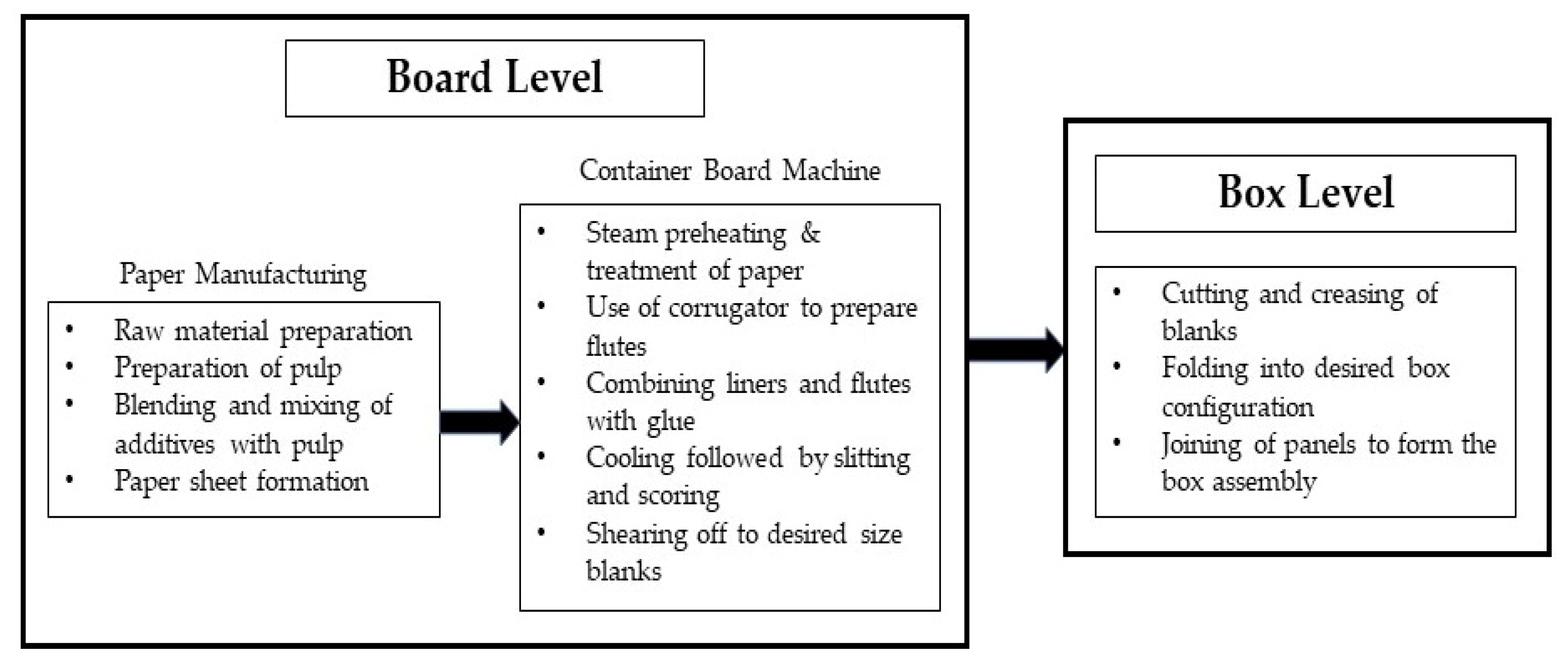
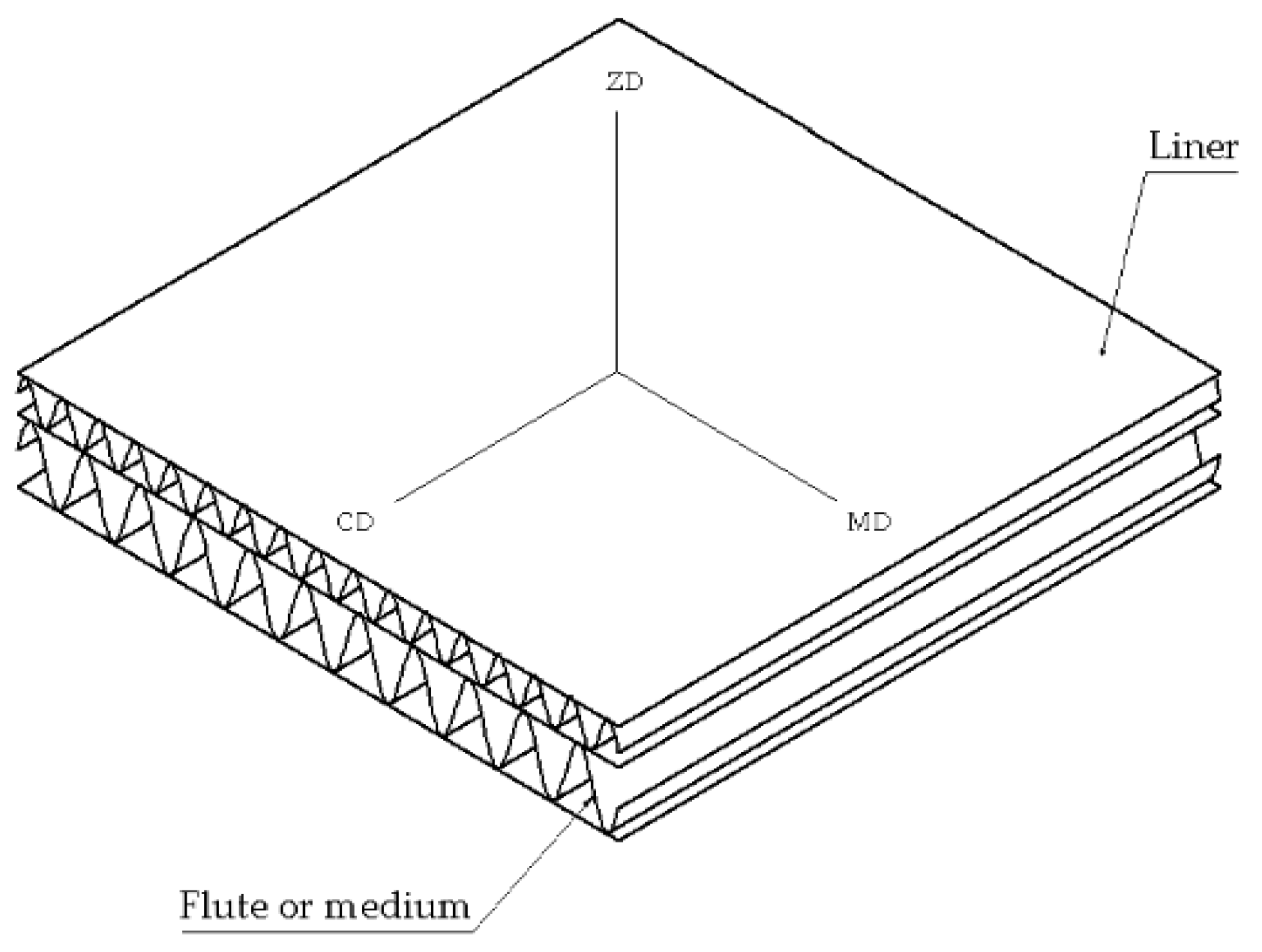
2. Materials and Methods
- (1)
- Machine direction (MD);
- (2)
- Cross-machine direction (CD);
- (3)
- Out-of-panel direction (ZD).
- (a)
- : Young’s modulus in MD;
- (b)
- : Young’s modulus in CD;
- (c)
- : Young’s modulus in ZD;
- (d)
- : Poisson’s ratios;
- (e)
- : Shear moduli.
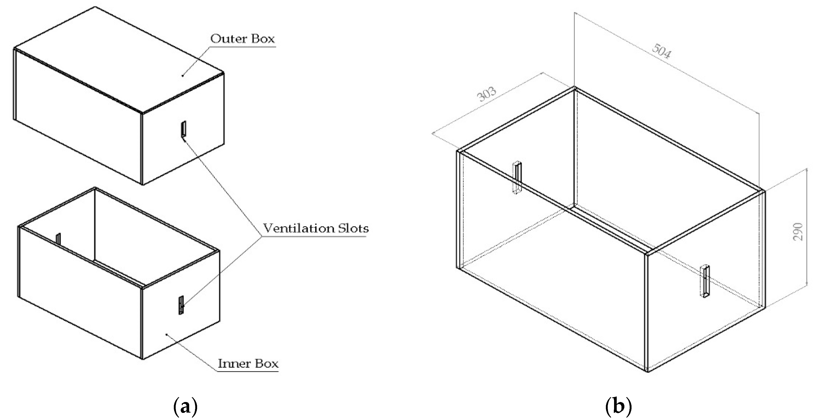
2.1. Box Properties
- Type of box: Telescopic type box;
- Box dimensions (Length, L × Width, B × Height, H): 504 × 303 × 290 mm;
- Number of plies: 5-ply or double-wall for maximum mass content of 16–20 kg as per Table 2 in IS 2771-1 (1990);
- Flute type: A > C > B
- Type-A flutes provide the best stacking strength and cushioning among all. Type-B has superior folding property and executes better strength along score lines. Type-C flutes consist of properties intermediate to Type-A and Type-B [27];
- Ventilation slot dimensions:
- ○
- Inner box → 70 × 15 mm
- ○
- Outer box → 60 × 15 mm
- Average compression strength: 500 kgf (~4903.32 N) with deflection less than 20 mm. This criterion has been benchmarked and considered for the failure of the packaging box in this study.
Mechanical Properties of Panel Constituents
2.2. Finite Element Simulation
2.2.1. Modelling
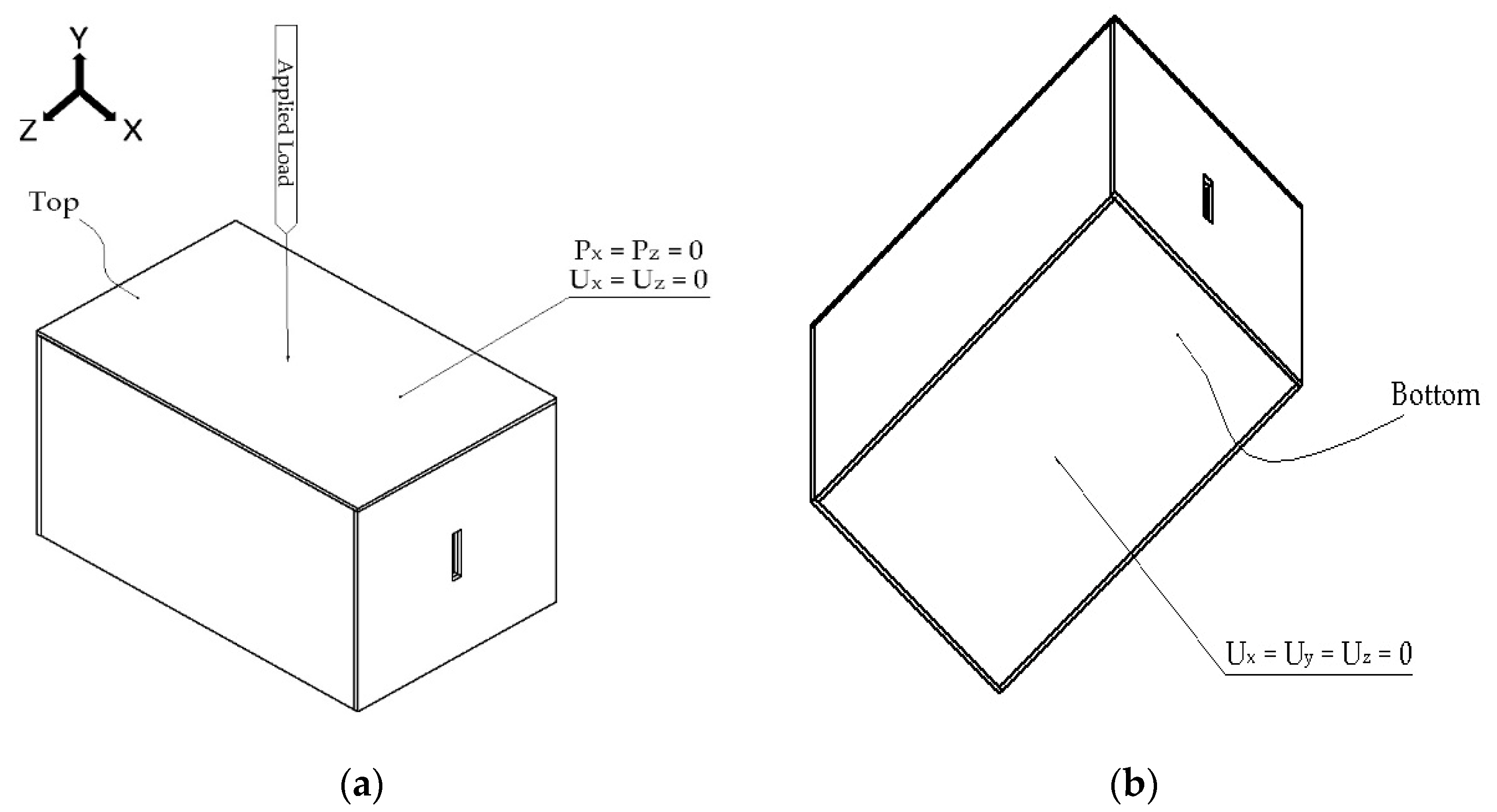
2.2.2. Boundary and Loading Conditions
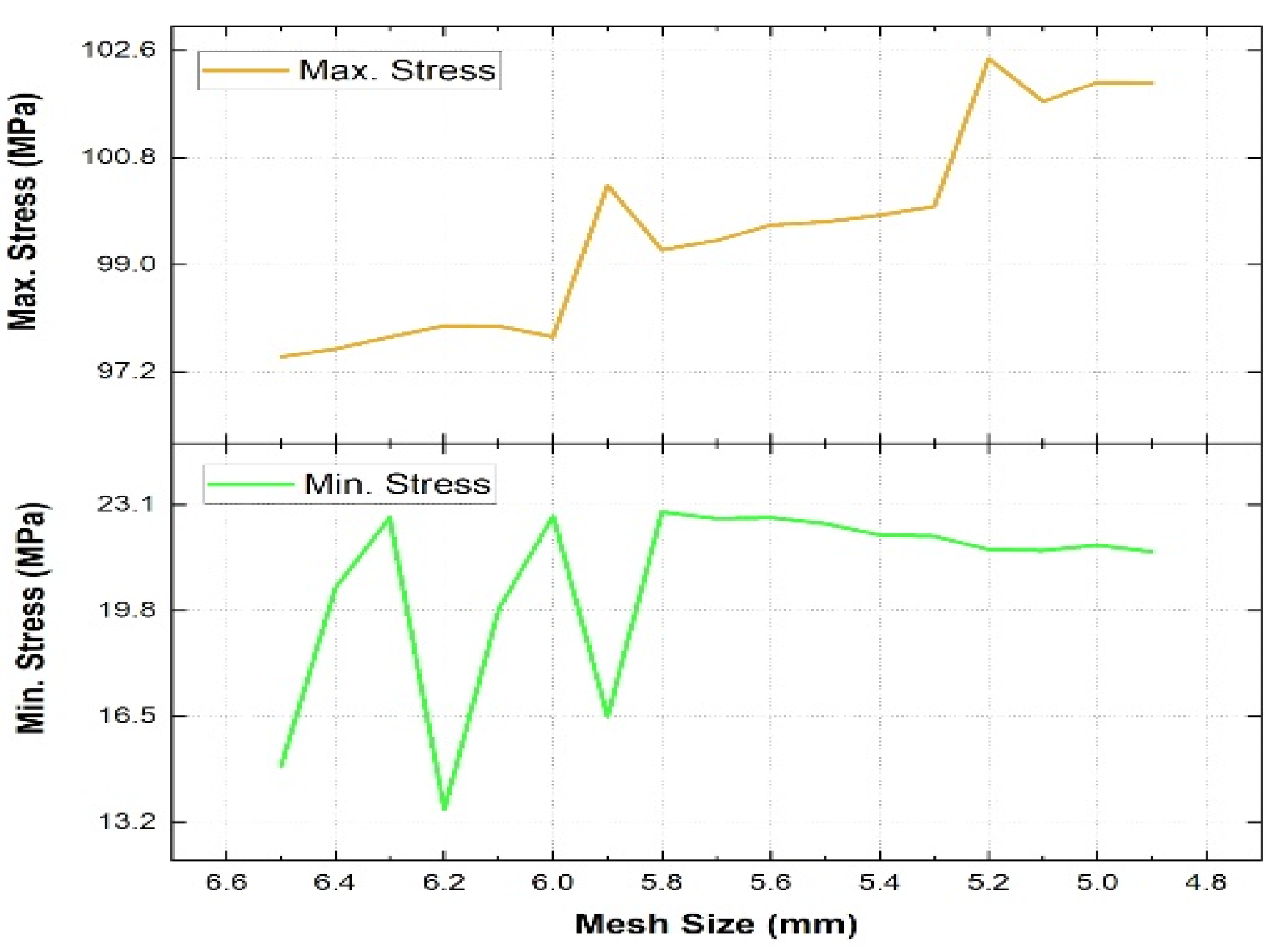
2.2.3. Mesh Sensitivity Analysis
3. Results and Discussions
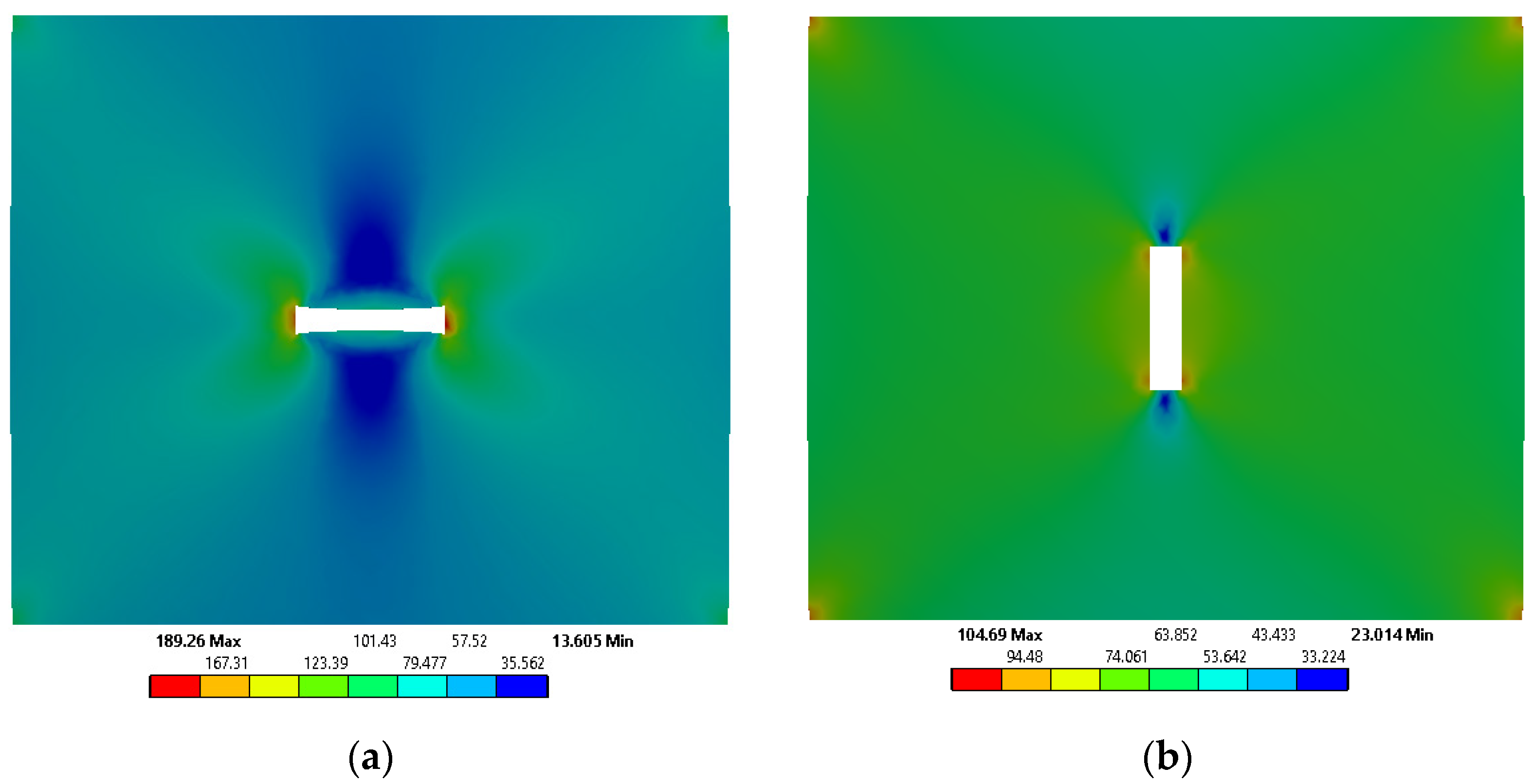
3.1. Effect of Change in Configuration of Ventilations Slots
- The increase in the dimensions of the slot on the outer box from 60 × 15 mm to 70 × 15 mm, similar to the inner box corresponding to an increase of 16.667% in slot area, will lead to a decrease in the volume of a box by ~0.08% and thus a reduction in resource utilization, item cost and net weight per box. This material saving can be realized with the high magnitude of boxes manufactured per year;
- A single die can be incorporated to fabricate the ventilation slots in the panels instead of two different in the present scenario;
- The abrupt change in the ventilation slot dimensions can lead to an increase in pressure drop across the slot interfaces resulting in inferior fluid flow characteristics and thus poor ventilation performance.
3.2. Effect on Box Performance on Replacement of Double-Ply Panels with Single-Ply Panels
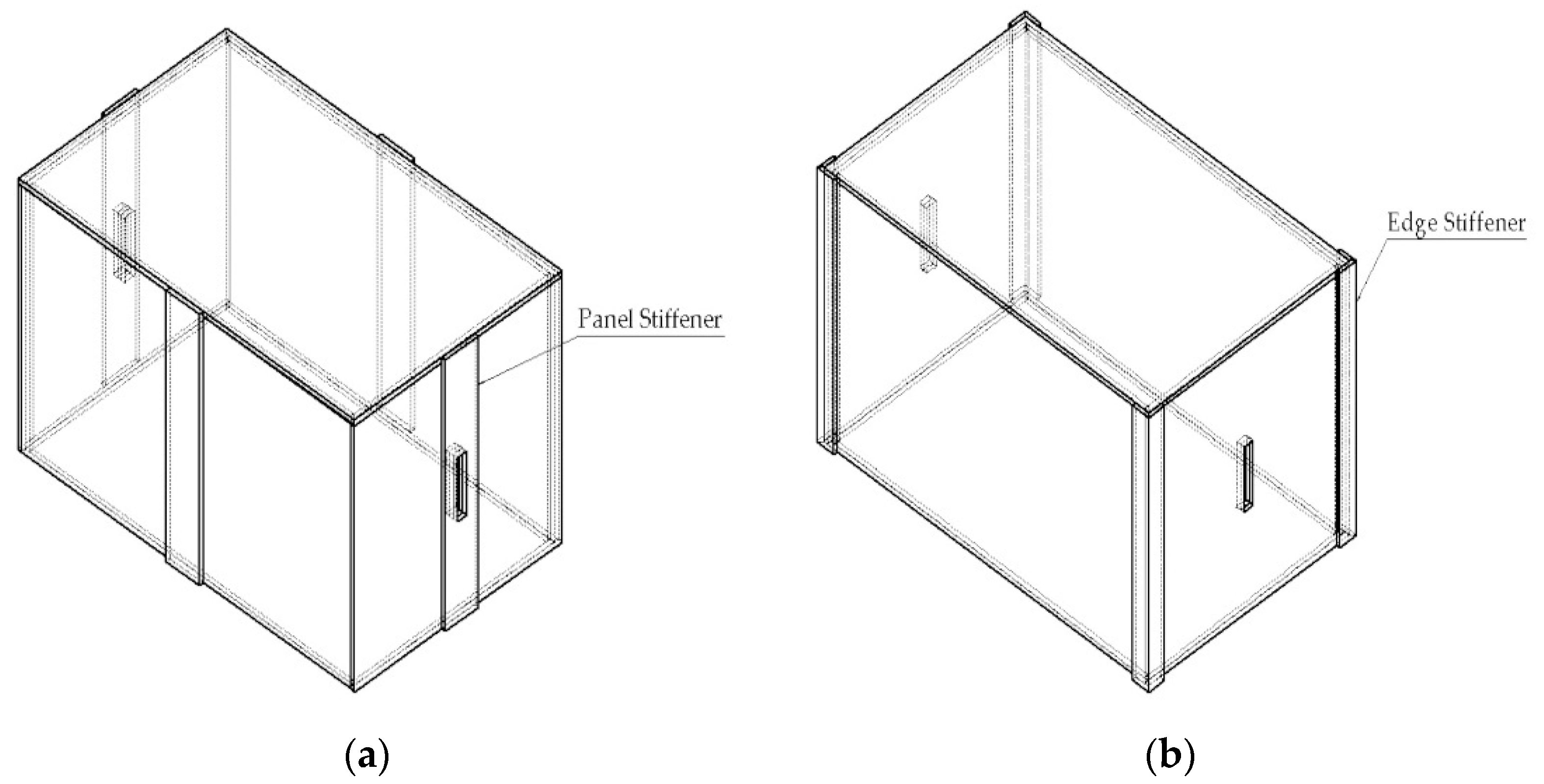
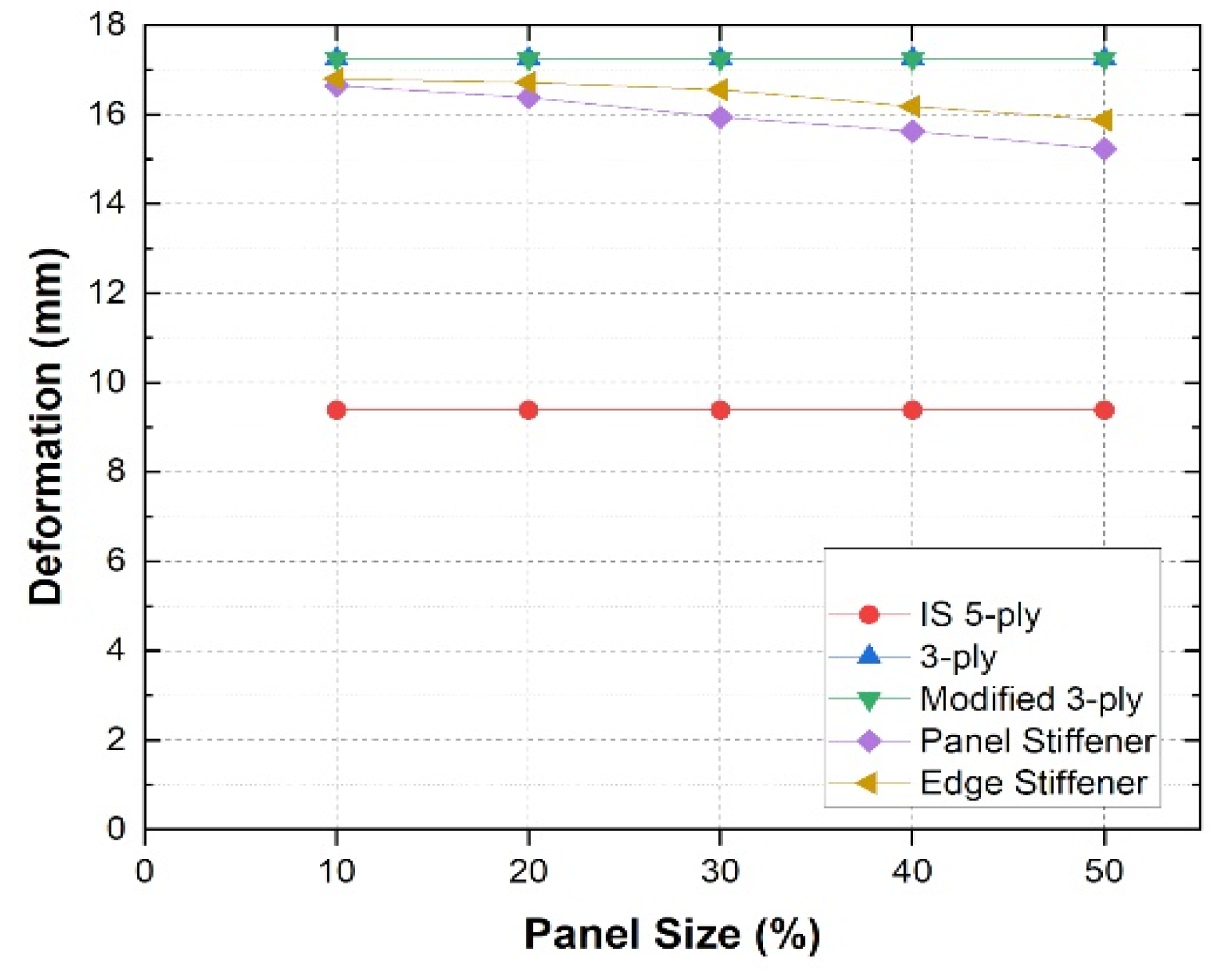
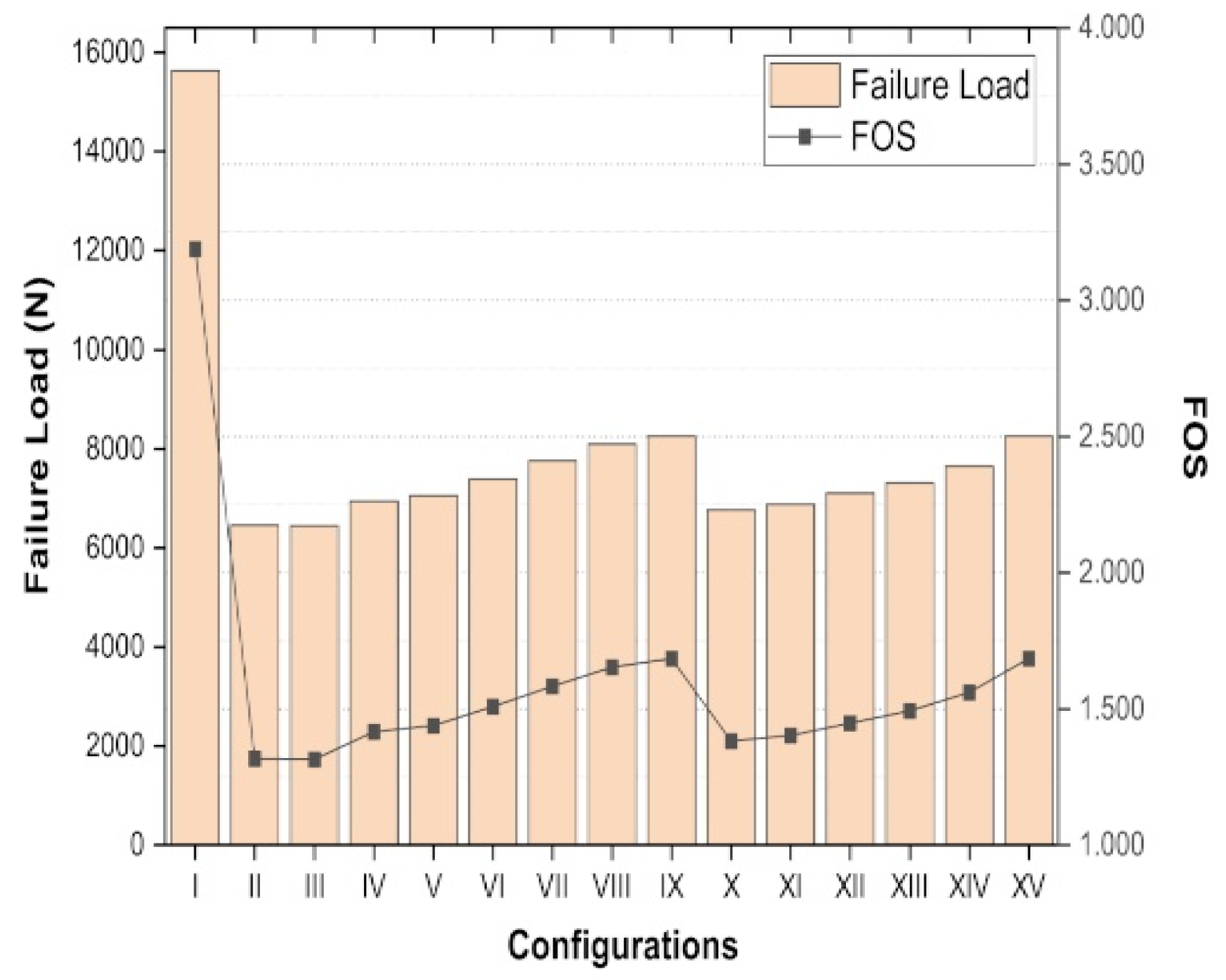
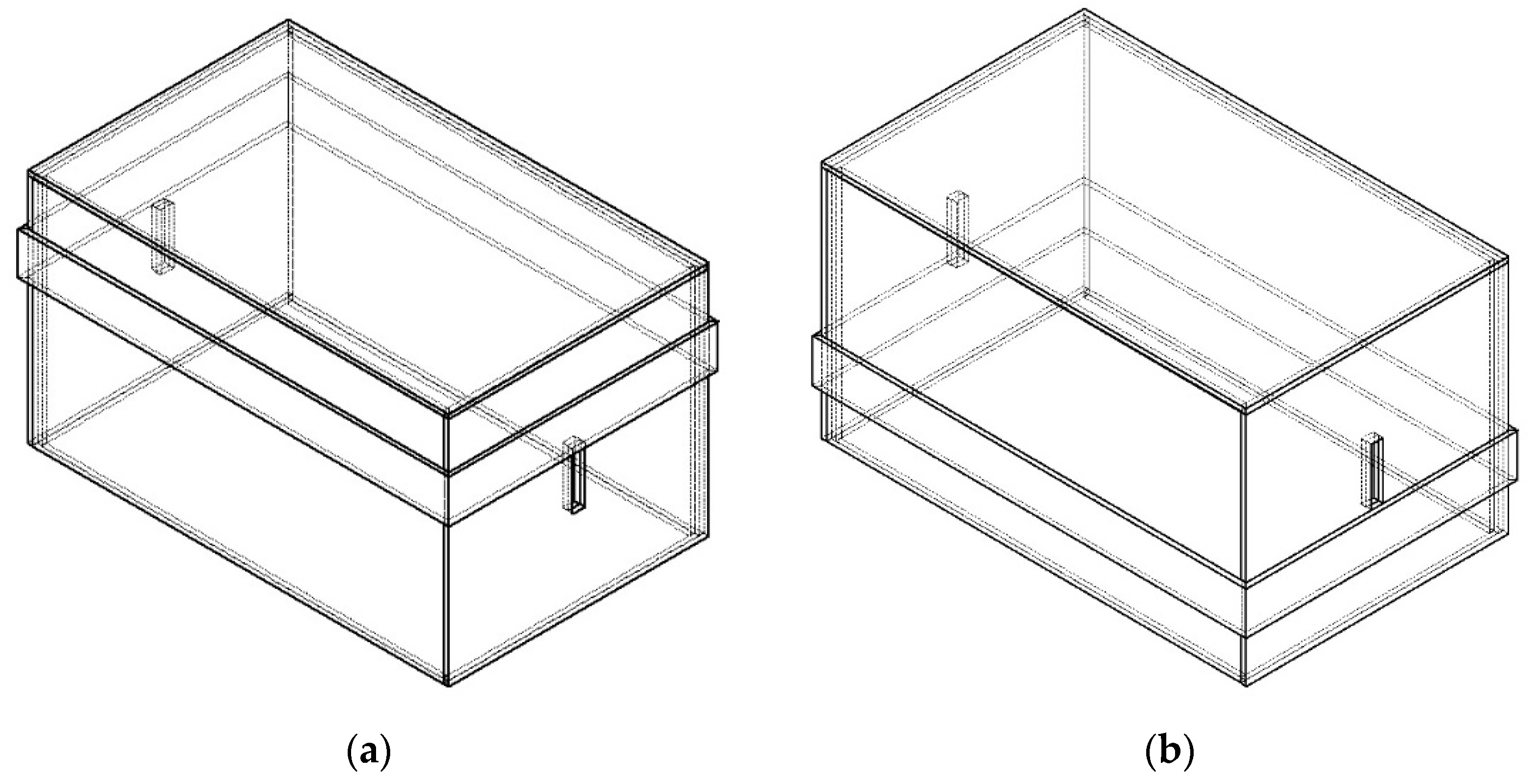
3.3. Effect of Stiffeners on the Box Compression Strength
- Staples and stitches: To fix the stiffeners to the panels of the container, wide crown staples can be used around the vertical edges of the stiffeners. Similarly, a portable stitching apparatus can be helpful to speed up this process and provide a uniform pattern attachment with the panels;
- Glue: Starch-based glue same as the one used for joining corrugating medium, and the liners can be utilized.
4. Conclusions
- Vertically oriented ventilation slots result in lower stress generation as compared to its horizontal counterpart slots. With regard to the shape of the slots, rectangular slots show lower stress generation than the oblong-shaped slots with a full depth ventilation slot reducing the maximum stress generation along with benefits in terms of material utilization. Hence, it can be concluded that the use of a full-depth vertical ventilation slot can improve the current IS design with reductions in terms of material utilization and overall cost;
- With the total deformation limited to below the standard recommendation, a 3-ply system can be proposed as a replacement for the current 5-ply IS package. This design modification can result in significant material saving of 34.558% and can help in mitigating the associated issues;
- The use of stiffeners can lead to improvement in the stacking performance of a package. With the introduction of stiffeners to the package, the stiffness of the structure improved that resulted in lowering of deformation and an increase in the loading capacity. The panel stiffeners’ performance was found to be superior when compared with the edge stiffeners as it resulted in lower deformation and higher FOS for the same width. The sole implementation of horizontal stiffener configuration displayed an inferior performance in terms of total deformation along with the increase in material utilization. The integration of the horizontal stiffeners as a combination with vertical stiffener configurations was not found be justifiable by the fact that the material utilization per box increased by a greater extent.
Author Contributions
Funding
Institutional Review Board Statement
Informed Consent Statement
Data Availability Statement
Acknowledgments
Conflicts of Interest
References
- Fadiji, T.; Berry, T.M.; Coetzee, C.J.; Opara, U.L. Mechanical Design and Performance Testing of Corrugated Packaging for the Postharvest Handling of Horticultural Produce. Biosyst. Eng. 2018, 171, 220–244. [Google Scholar] [CrossRef]
- Biancolini, M.E.; Brutti, C. Numerical and Experimental Investigation of the Strength of Corrugated Board Packages. Packag. Technol. Sci. 2003, 16, 47–60. [Google Scholar] [CrossRef]
- Pathare, P.B.; Opara, U.L.; Delele, M.A. Analysis of mechanical properties of vented corrugated container for fresh horticultural produce by finite element method. In Proceedings of the Silos and Granular Materials (SIGMA), International Conference of Agricultural Engineering-CIGR-AgEng: Agriculture and Engineering for a Healthier Life, Valencia, Spain, 8–12 July 2012. [Google Scholar]
- IS 11844 (1987). Corrugated Fibreboard Boxes for Transport Packaging of Apples; Bureau of Indian Standards (BIS): New Delhi, India, 1987. [Google Scholar]
- Didone, M.; Saxena, P.; Meijer, E.B.; Tosello, G.; Bissacco, G.; Mcaloone, T.C.; Pigosso, D.C.A.; Howard, T.J. Moulded Pulp Manufacturing: Overview and Prospects for the Process Technology. Packag. Technol. Sci. 2017, 30, 231–249. [Google Scholar] [CrossRef] [Green Version]
- Saxena, P.; Bissacco, G.; Meinert, K.; Danielak, A.H.; Ribó, M.M.; Pedersen, D.B. Soft tooling process chain for the manufacturing of micro-functional features on molds used for molding of paper bottles. J. Manuf. Proc. 2020, 54, 129–137. [Google Scholar] [CrossRef]
- Gustafsson, P.J.; Niskanen, K. Paper as an engineering material. In Mechanics of Paper Products, 1st ed.; Niskanen, K., Ed.; De Gruyter: Berlin, Germany, 2012; pp. 5–26. [Google Scholar]
- IS 6481 (1971). Guide for Principal Uses and Styles of Fibreboard Containers, Third Reprint; Bureau of Indian Standards (BIS): New Delhi, India, 1993. [Google Scholar]
- Saxena, P.; Bissacco, G.; Meinert, K.; Bedka, F.J. Mold design and fabrication for production of thermoformed paper-based packaging products. J. Manuf. Proc. 2020, 58, 311–321. [Google Scholar] [CrossRef]
- Fadiji, T.; Ambaw, A.; Coetzee, C.J.; Berry, T.M.; Opara, U.L. Application of finite element analysis to predict the me-chanical strength of ventilated corrugated paperboard packaging for handling fresh produce. Biosyst. Eng. 2018, 174, 260–281. [Google Scholar] [CrossRef]
- Kueh, C.S.L. Modelling Buckling and Post-buckling Behaviours of Corrugated Paperboard Structures. Ph.D. Thesis, The University of Waikato, Hamilton, New Zealand, 2012. [Google Scholar]
- Talbi, N.; Batti, A.; Ayad, R.; Guo, Y.Q. An analytical homogenization model for finite element modelling of corrugated cardboard. Compos. Struct. 2009, 88, 280–289. [Google Scholar] [CrossRef]
- Patel, P.; Nordstrand, T.; Carlsson, L.A. Local buckling and collapse of corrugated board under biaxial stress. Compos. Struct 1997, 39, 93–110. [Google Scholar] [CrossRef]
- Hägglund, R.; Carlsson, L.A. Paper. Packaging performance. In Mechanics of Paper Products, 1st ed.; Niskanen, K., Ed.; De Gruyter: Berlin, Germany, 2012; pp. 29–48. [Google Scholar]
- Rodrigues, D.; Pereira, J. Experimental Tests and Numerical Simulations for Failure Investigation on Corrugated Boxes Used on Household Appliance Packaging. J. Appl. Packag. Res. 2018, 10, 6. [Google Scholar]
- Fadiji, T.; Berry, T.; Coetzee, C.; Opara, U.L. Investigating the Mechanical Properties of Paperboard Packaging Material for Handling Fresh Produce Under Different Environmental Conditions: Experimental Analysis and Finite Element Modelling. J. Appl. Packag. Res. 2017, 9, 3. [Google Scholar]
- Fadiji, T.; Coetzee, C.; Opara, U.L. Compression strength of ventilated corrugated paperboard packages: Numerical modelling, experimental validation and effects of vent geometric design. Biosyst. Eng. 2016, 151, 231–247. [Google Scholar] [CrossRef]
- Singh, J.; Olsen, E.; Singh, S.P.; Manley, J.; Wallace, F. The Effect of Ventilation and Hand Holes on Loss of Compression Strength in Corrugated Boxes. J. Appl. Packag. Res. 2008, 2, 227–238. [Google Scholar]
- Lee, M.H.; Park, J.M. Flexural Stiffness of Selected Corrugated Structures. Packag. Technol. Sci. 2004, 17, 275–286. [Google Scholar] [CrossRef]
- IS 4261 (2001). Glossary of Terms Relating to Paper- and Pulp-Based Packaging Materials; Bureau of Indian Standards (BIS): New Delhi, India, 2001. [Google Scholar]
- Aboura, Z.; Talbi, N.; Allaoui, S.; Benzeggagh, M.L. Elastic Behavior of Corrugated Cardboard: Experiments and Modeling. Compos. Struct. 2004, 63, 53–62. [Google Scholar] [CrossRef] [Green Version]
- Garbowski, T.; Gajewski, T.; Grabski, J.K. Estimation of the compressive strength of corrugated cardboard boxes with various perforations. Energies 2021, 14, 1095. [Google Scholar] [CrossRef]
- Biancolini, M.E.; Brutti, C.; Porziani, S. Corrugated Board Containers Design Methods. Int. J. Comput. Mater. Sci. Surf. Eng. 2010, 3, 143–163. [Google Scholar] [CrossRef]
- Basri, M.S.M.; Nor, M.Z.M.; Shamsudin, R.; Tawakkal, I.S.M.A.; Ghani, N.H.A.; Kamarudin, K.M.; Mustafah, A.M. Effects of different fluting medium geometries on von-Mises stress and deformation in single fluted board: A three-dimensional finite element analysis. Adv. Agric. Food Res. J. 2021, 2. [Google Scholar] [CrossRef]
- Hutton, D.V. Fundamental of Finite Element Analysis; The McGraw-Hill Companies: Boston, MA, USA, 2004; p. 370. [Google Scholar]
- ANSYS, Inc. Workbench User Guide; ANSYS Inc.: Canonsburg, PA, USA, 2018. [Google Scholar]
- IS 2771-1 (1990). Corrugated Fibreboard Boxes, Part 1: General Requirements; Bureau of Indian Standards (BIS): New Delhi, India, 2003. [Google Scholar]
- Han, J.; Park, J.M. Finite Element Analysis of Vent/Hand Hole Designs for Corrugated Fibreboard Boxes. Packag. Technol. Sci. 2007, 20, 39–47. [Google Scholar] [CrossRef]
- Sadd, M.H. Elasticity: Theory, Applications, and Numerics (2e); Academic Press: Burlington, MA, USA, 2009; p. 67. [Google Scholar]


| Property | Values for DW Panels | Values for SW Panels |
|---|---|---|
| (MPa) | 3690.00 | 3114.7 |
| (MPa) | 1560.00 | 1611.2 |
| (MPa) | 18.45 | 15.574 |
| 0.28 | 0.28 | |
| 0.12 | 0.12 | |
| 0.12 | 0.12 | |
| (MPa) | 928.51 | 866.95 |
| (MPa) | 67.09 | 46.034 |
| (MPa) | 44.57 | 56.631 |
| Parameter | DW with AB/F (Flutes) | SW with A/F (Flutes) |
|---|---|---|
| Thickness of liners (mm) | 0.253 | 0.253 |
| Height of A flute (mm) | 5.161 | 5.422 |
| Height of B flute (mm) | 2.911 | - |
| Number of corrugations (Per 300 mm) | A flute: 35 B flute: 54 | 35 |
| Slot Configuration | Maximum Stress | Minimum Stress |
|---|---|---|
| IS box | 104.510 | 22.952 |
| Full depth slot | 100.220 | 35.901 |
| Vertical oblong shape | 105.940 | 25.452 |
| S. No. | Box Configuration | Total Deformation (mm) | Percentage Increase w.r.t IS 5-Ply System (%) | Equivalent Stress (MPa) |
|---|---|---|---|---|
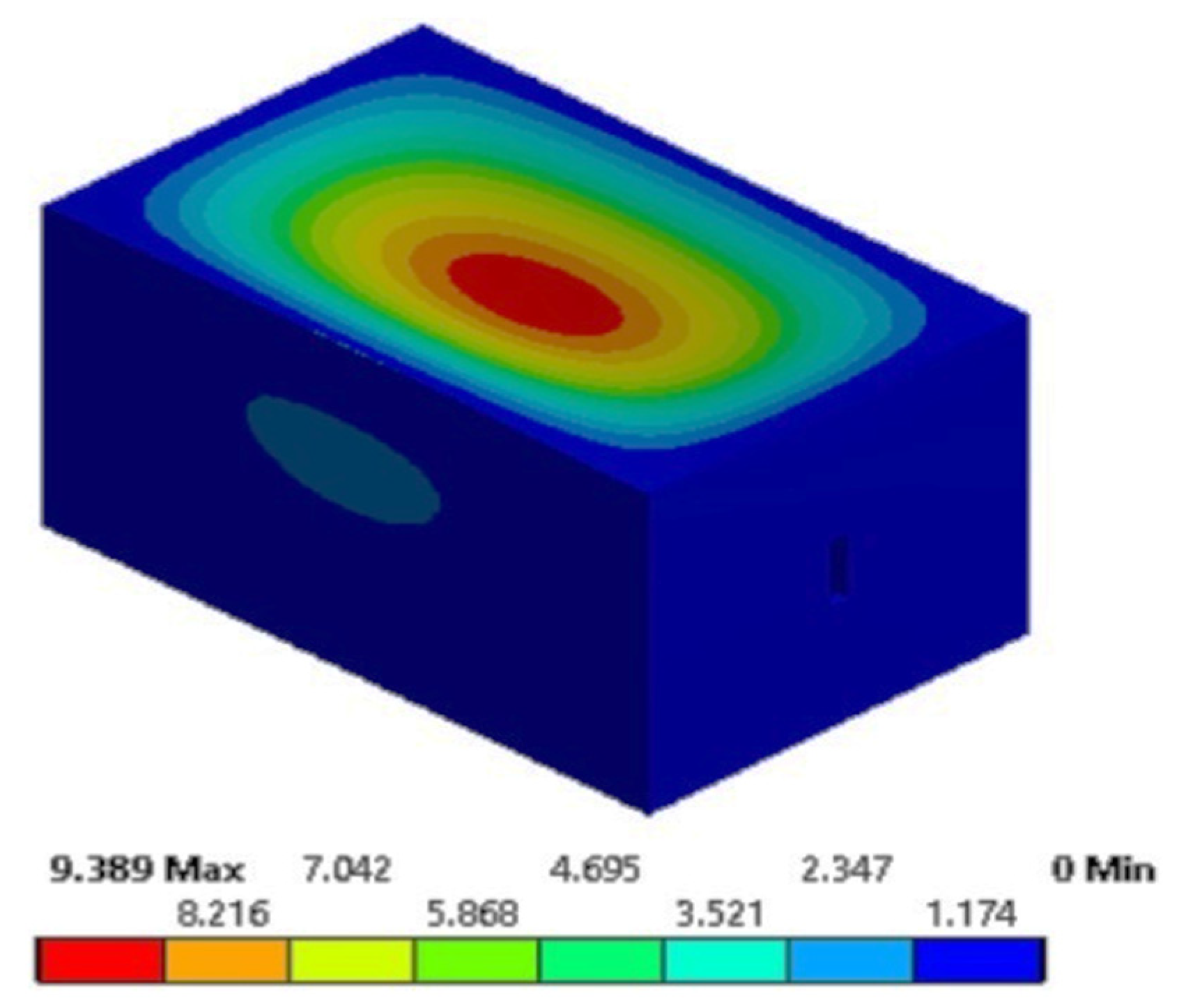
| 1. | DW system | 9.389 | - | 8.485 |
| 2. | SW system | 17.252 | 83.747 | 16.611 |
| 3. | SW system with full-depth slot | 17.252 | 83.747 | 16.611 |
| Configuration | Description | Configuration | Description |
|---|---|---|---|
| I | IS 5-ply | IX | 61.78% panel stiffener |
| II | 3-ply | X | 10% edge stiffener |
| III | Modified 3-ply | XI | 20% edge stiffener |
| IV | 10% panel stiffener | XII | 30% edge stiffener |
| V | 20% panel stiffener | XIII | 40% edge stiffener |
| VI | 30% panel stiffener | XIV | 50% edge stiffener |
| VII | 40% panel stiffener | XV | 59.07% edge stiffener |
| VIII | 50% panel stiffener |
Publisher’s Note: MDPI stays neutral with regard to jurisdictional claims in published maps and institutional affiliations. |
© 2021 by the authors. Licensee MDPI, Basel, Switzerland. This article is an open access article distributed under the terms and conditions of the Creative Commons Attribution (CC BY) license (https://creativecommons.org/licenses/by/4.0/).
Share and Cite
Kalita, N.; Saxena, P.; Talha, M. Influence of Stiffeners for Improving the Compressive Strength of Ventilated Corrugated Packages Using Finite Element Modelling Technique. Sustainability 2021, 13, 13926. https://doi.org/10.3390/su132413926
Kalita N, Saxena P, Talha M. Influence of Stiffeners for Improving the Compressive Strength of Ventilated Corrugated Packages Using Finite Element Modelling Technique. Sustainability. 2021; 13(24):13926. https://doi.org/10.3390/su132413926
Chicago/Turabian StyleKalita, Nilotpal, Prateek Saxena, and Mohammad Talha. 2021. "Influence of Stiffeners for Improving the Compressive Strength of Ventilated Corrugated Packages Using Finite Element Modelling Technique" Sustainability 13, no. 24: 13926. https://doi.org/10.3390/su132413926
APA StyleKalita, N., Saxena, P., & Talha, M. (2021). Influence of Stiffeners for Improving the Compressive Strength of Ventilated Corrugated Packages Using Finite Element Modelling Technique. Sustainability, 13(24), 13926. https://doi.org/10.3390/su132413926