Article

Influence of Iron Filing Waste on the Performance of Warm Mix Asphalt

1
School of Science, Engineering & Environment, University of Salford, Manchester M5 4WT, UK
2
Department of Civil Engineering, University of Baghdad, Baghdad 10071, Iraq
3
Civil Engineering Department, College of Engineering, Al-Nahrain University, Baghdad 10071, Iraq
4
Ministry of Higher Education and Scientific Research, Baghdad 10072, Iraq
*
Author to whom correspondence should be addressed.
Sustainability 2021, 13(24), 13828; https://doi.org/10.3390/su132413828
Submission received: 1 November 2021 / Revised: 6 December 2021 / Accepted: 11 December 2021 / Published: 14 December 2021

Abstract

:
Recently, interest in the use of projectiles in research on recycling waste materials for construction applications has grown. Using recycled materials for the construction of asphalt concrete pavement, in the meantime, has become a topic of research due to its significant benefits, such as cost savings and reduced environmental impacts. This study reports on comprehensive experimental research conducted using a typical mechanical milling waste, iron filing waste (IFW), as an alternative fine aggregate for warm mix asphalt (WMA) for pavement wearing surface applications. A type of IFW from a local machine workshop was used to replace the conventional fine aggregate, fine natural sand (FNS), at percentages of 25%, 50% 75%, and 100% by the weight of FNS of the size passing sieve No. 50. Experimental tests were conducted on the mixes to compare their Marshall properties, resilient moduli, rutting and fatigue resistance, and moisture susceptibility. Finally, a performance analysis was carried out using the VESYS 5W software on the constructed pavement using the IFW mixes. Both the experiment and the modeling work demonstrated that IFW can be an effective alternative resource for replacing natural fine aggregate in WMA concrete and provided details on the optimum rate based on the comprehensive data obtained first hand.

1. Introduction

Over the past few decades, waste generated by human beings has become a serious global issue facing sustainable development. The progressively growing volume of waste has led to the use of natural areas for landfill, causing huge impacts on the environment and ecosystem [1]. Only the implementation of a circular economy will be able to achieve environmental and economic sustainability. Innovations regarding the recycling and reuse of wastes can help to not only preserve valuable natural resources but can also reduce the costs of disposal and environmental pollution [2].
Pavement construction is a sector that consumes a large amount of natural resources. Asphalt concrete, a vital material used for flexible pavement, is used in 95% of all constructed roads and highways around the world [3]. Aggregates typically make up nearly 95% of the total weight of asphalt concrete. Their quality affects the properties of concrete mixes and the performance of the constructed pavement. The high demand for aggregates has led to a considerable global depletion of natural resources and consequently has caused an issue regarding their sustainable supply [4]. Thus far, great efforts have been made to use recycled wastes as alternative aggregates for producing asphalt concrete. These wastes include crushed glass, recycled aggregate from demolished concrete, discarded ceramics, and steel slag [5,6,7,8,9,10,11,12,13,14,15,16].
Local workshops and factories produce a considerable amount of iron filing waste (IFW) across the world. Due to its excellent durability and high strength, IFW has been used in many civil engineering applications, such as concrete manufacturing, soil stabilization, and asphalt pavement repair for microcracks [17,18,19,20]. IFW powder has also been used as a filler replacement in hot mix asphalt (HMA). Arabani and Mirabdolazimi [21] reported on the use of iron powder with a maximum size of 2.36 mm at a of 12% content in HMA to enhance the dynamic properties of the mix and the mechanical behavior of the constructed pavement. Jendia and Tabash [22] found that HMA, containing 5% iron waste used as both a filler and fine aggregate caused a nearly 23% improvement in the stability of binder layer application. Gallego et al. [5], who studied the effect of the use of different HMA additives on susceptibility to microwave heating, found that iron filings of 0.063–0.25 mm and at two contents (0.2% and 0.4%) of total mix weight showed no impact on the heating process of mixtures. However, Franesqui et al. [19], who studied the self-healing of surface cracks of HMA under microwave heating, noticed that mixes containing additional iron filings with a particle size in the range of 1–2 mm showed a longer service life and lower cost given the self-healing of microwave-heated cracks. Al Akhrass [23], who studied the self-healing properties of asphalt mix for a wearing layer application, used IFW to partially replace fine aggregate with a particle size less than 4.75 mm at rates of 0, 2.5, 5, 7.5, and 10% and found that IFW increased the thermal conductivity of mixes and helped to improve the self-healing properties. In particular, the mix with a 7.5% IFW replacement rate showed the best crack-healing ability. Another study by Khilafat and Msallam [24] recommended that IFW should not be used for pavement after studying the use of 5% IFW as a filler in HMA. However, the study by Mohammed [25], which compared the HMA using IFW as a mineral filler at rates 25%, 50%, 75%, and 100% by weight, showed that a 50% mineral filler replacement using IFW generated an optimal improvement in stability (by 24%) and flowability (by 18%). Another study by Eisa [26] also noticed that using IFW to replace the limestone dust filler improved the Marshall properties of the HMA mix for surface layer application; the optimal replacement rate was obtained at a level of 25% replacement by weight.
Fine aggregate plays a main role in the mechanical properties of asphalt concrete and consumes a large amount of natural sand, which is traditionally the major resource used. Ahlrich [27] studied the effect of the physical properties of fine aggregate (such as its texture, angularity, and particle shape) on asphalt concrete subjected to aircraft landing. It was found that the use of natural sand up to 20% of the total weight of aggregate increased the potential degree of rutting. Another study by Zaniewski and Srinivasan [28] showed that a mix created using natural sand as a fine aggregate smaller than 4.75 mm at a volume of 40% by total weight decreased the rutting resistance of the mix compared with a mix created using no natural sand. Albayati and Abdulsattar [29] studied asphalt mixtures created using two types of natural sand—i.e., river and desert sand—at different contents and found that the use of natural sand had negative effects on the Marshall properties, durability, and permanent deformation of the asphalt concrete compared with a mix created using crushed sand. These findings encouraged researchers to find a better alternative fine aggregate material as a replacement for natural sand to improve the mechanical properties of asphalt concrete. Thus far, few studies have reported the sole use of IFW as a replacement for fine sand aggregate in asphalt concrete. To fill this gap, this work reports a comprehensive study on the mechanical properties and durability of warm mix asphalt (WMA) concrete created using IFW as a replacement for original fine natural sand (FNS) in a mixture for wearing layer application.

2. Materials

The raw materials used in the experimental work were all locally available and used for pavement construction in the region of Baghdad city.

2.1. Asphalt Cement

The asphalt cement was obtained from Doura refinery in the southwest of Baghdad. It was tested to determine its the grade requirement for superpave performance. Table 1 shows the results and the specifications. It can be clearly seen that the performance grade can be taken as PG64-16, while the m-value for PAV age was calculated as 0.38.

2.2. Fine and Coarse Aggregates

The fine and coarse aggregates were obtained from Al-Nibaie quarry in the north of Baghdad. Lab tests were conducted to obtain the physical properties of the aggregates. The results are listed in Table 2. All the data satisfy the relevant specifications. Asphalt concrete mixture was prepared for wearing layer application according to the aggregate gradation of Iraqi SCRB/R9 (“State Corporation for Roads and Bridges”) [30], as illustrated in Figure 1. The proportion of fine and coarse aggregates is 60% and 40%, respectively.

2.3. Mineral Filler

Limestone dust was used as a conventional filler. It was manufactured by grinding limestone in a local lime plant located in the southeast of Iraq. Table 3 gives the chemical composition as well as physical properties of the limestone material.

2.4. Iron Filing Waste (IFW)

The IFW used for the study was collected from iron milling residual left in a local blacksmith workshop in Baghdad city. The IFW was sieved to a particle size between 0.075 (sieve No. 200) and 0.3 mm (sieve No. 50) and then used as a partial replacement for the FNS at four different rates—i.e., 25, 50, 75, and 100%. Figure 2 shows the IFW and FNS.

2.5. Warm Asphalt Mixture Additive

Aspha-min powder was used as an additive. This powder is composed of hydrothermally crystallized sodium aluminosilicate containing nearly 21% water by weight. Table 4 gives its chemical composition and physical properties.

3. Specimen Preparation

In total, five asphalt concrete mixes were made using the IFW at replacement rates of 0, 25, 50, 75, and 100%. The optimum asphalt content (O.A.C.) used for each mix was determined following the design technique of the Marshall test (ASTM D6926) [31]. The O.A.C. decided on was thereafter adopted for the creation of all the specimens used for the experimental tests.
When making the specimens, the prepared aggregates were first mixed in a bowl with mineral filler. Thereafter, the mixtures were heated for 6 h at a temperature of 120 °C. In the meantime, asphalt cement was heated separately for 2 h under a controlled temperature of 155 °C to achieve a viscosity of 170 c.St. Figure 3 shows the linear relationship between temperature and viscosity. Following the heating, the aspha-min additive was added to the heated aggregate mixtures at 0.3% by weight and blended for 30 s. Finally, the O.A.C. for asphalt cement was added to each mixture. The mixtures were thoroughly blended in a container for two minutes at a temperature of 125 °C, which was 30 °C lower than the HMA temperature of 155 °C. Thereafter, these mixtures were placed back into an oven for another 10 min under a controlled temperature of 115 °C. After 10 min, the mixes were cast into molds and compacted to create the specimens for testing. Three types of molds were used. The first was cylindrical with a diameter of 101.6 mm and height of 76.2 mm and was used for the specimens created for the Marshall test and indirect splitting tensile test. The second was also cylindrical and of the same diameter but had a 254 mm height; this mold was used for the specimens created for the resilient modulus test as well as the permanent deformation test. The last mold was a prism box with the dimensions 76 mm width × 76 mm depth × 381 mm length; this mold was used for the specimens created for the fatigue test.

4. Experiments

4.1. Marshall Test

The Marshall test was conducted following the ASTMD6926 [31] standard to determine the O.A.C. A total of 5 different asphalt contents were added to each of the designed aggregate and additive mixtures, which were mixed according to the methods specified in Section 3 above. The prepared mixes were then loaded into the molds and compacted up to 75 times at both ends of the molds using a Marshall compactor to produce the test specimens. The O.A.C. was determined in terms of the average of the three asphalt cement contents corresponding to maximum stability, maximum unit weight, and 4% air voids, respectively [32].

4.2. Mechanical Property Tests

4.2.1. Resilient Modulus

The resilient modulus (Mr) was tested using cylindrical specimens with a diameter of 101.6 mm and height of 203.2 mm. The specimens were produced using a method that was previously described (Albayati 2006 [33]). A repetitive compressive load was applied in the axial direction using a pneumatic system. At a frequency of 1 Hz, the load was 137.9 kPa (20 psi) for 0.1 s and none for the remaining 0.9 s in each cycle. The temperature was controlled at 20 °C. The Mr was calculated in terms of the definition given below:
Mr = σ r d / h
where σ is the axial compressive stress, rd is the axial resilient deflection determined by utilizing LVDT at 50–100 load repetitions (linear variable differential transformer), and h is the height of the specimen.

4.2.2. Permanent Deformation

The permanent deformation was evaluated using similar tests for the resilient modulus. The specimens, however, were subjected to repeated cyclic loading until they either collapsed or reached the maximum of 10,000 repetitions. The temperature was maintained at 40 °C in the test.

4.3. Durability Tests

4.3.1. Moisture Susceptibility

The moisture susceptibility of all mixes was assessed according to the standard ASTM-D-4867 [34]. Six cylindrical specimens were prepared for each mix. They were made by Marshall compaction with 51–64 blows on each side, leaving them with a targeted AV in the range of 6–8%. The final specimens had a diameter of 101.6 mm and a height of 63 mm. The six specimens were split into two groups of three. One of the groups was tested under room temperature (25 °C) conditions and termed “unconditioned specimens”. The other group, known as conditioned specimens, was placed into a bottle filled with water under the same temperature (25 °C). The bottle was then vacuumed under a suction of 70 kPa or 525 mm Hg for 5 min to cause the specimens in it to achieve a 55–80% degree of water saturation. After that, the specimens were instantly exposed to freezing and thawing cycles by firstly subjecting them to a temperature of −18 ± 2 °C for 16 h and then immediately moving them to a temperature of 60 ± 1 °C for another 24 h. Thereafter, all the specimens in the two groups were tested at room temperature (25 °C) to determine their indirect tensile strength (ITS) and tensile strength ratio (TSR) in terms of the definition below:
ITS = 2   P π   h   d
TSR = I T S c I T S u c
where P is the splitting load, h is the cylindrical specimen’s height, and d is the diameter. ITSC and ITSUC stand for the conditioned and unconditioned indirect tensile strength, respectively.

4.3.2. Flexural Fatigue

The prism beam specimens with dimensions of W × D × L = 76 mm × 76 mm × 381 mm were tested to determine the material fatigue life using the three-point bending test under a controlled temperature of 20 °C. A repetitive load was applied at a frequency of 2 Hz using a pneumatic system. In each cycle, the load was applied for 0.1 s followed by resting for 0.4 s. At the 50th load repetition, the vertical central deflection of the beam was recorded as a pseudo initial value. Lastly, the total number of load repetitions for each specimen until failure was also recorded. A total of six different load magnitudes were evaluated to determine the relationship between the maximum repetitive load number and the pseudo initial tensile strain at the bottom of the middle position of the span. The initial tensile stain was determined at a number of 50–100 load repetitions according to Equation (4):
ε t   = 12   h   Δ 3   L 2 4 a 2
where εt is the initial tensile strain, h is the beam height, Δ is the recorded flexural deformation at the middle position between two supports, L is length of the beam, and a is the distance between load to the support (over three beam lengths).

5. Results and Discussion

5.1. Scanning Electron Microscope Analysis

The exterior morphology (texture) and crystalline structure of the IFW and FNS were compared using scanning electron microscope (SEM) analysis at two magnification levels—i.e., 0.5 kx and 5 kx. The results are shown in Figure 4. Comparing Figure 4a,b, it can be clearly seen that the FNS particles have even sizes and angular shapes, while the IFW particles have large variations in their size and a lamellar shape. Comparing Figure 4c,d, it can be seen that the crystal grains of the FNS are generally smaller and have flat and slender shapes with sharp corners. However, most of the IFW grains are much larger, with a characteristic size of about (0.5 × 0.2) mm and a flat lamellar shape with a thickness of less than 0.05 mm. The dimensions of the plates are about the same, since they were created by shredding metal foil.

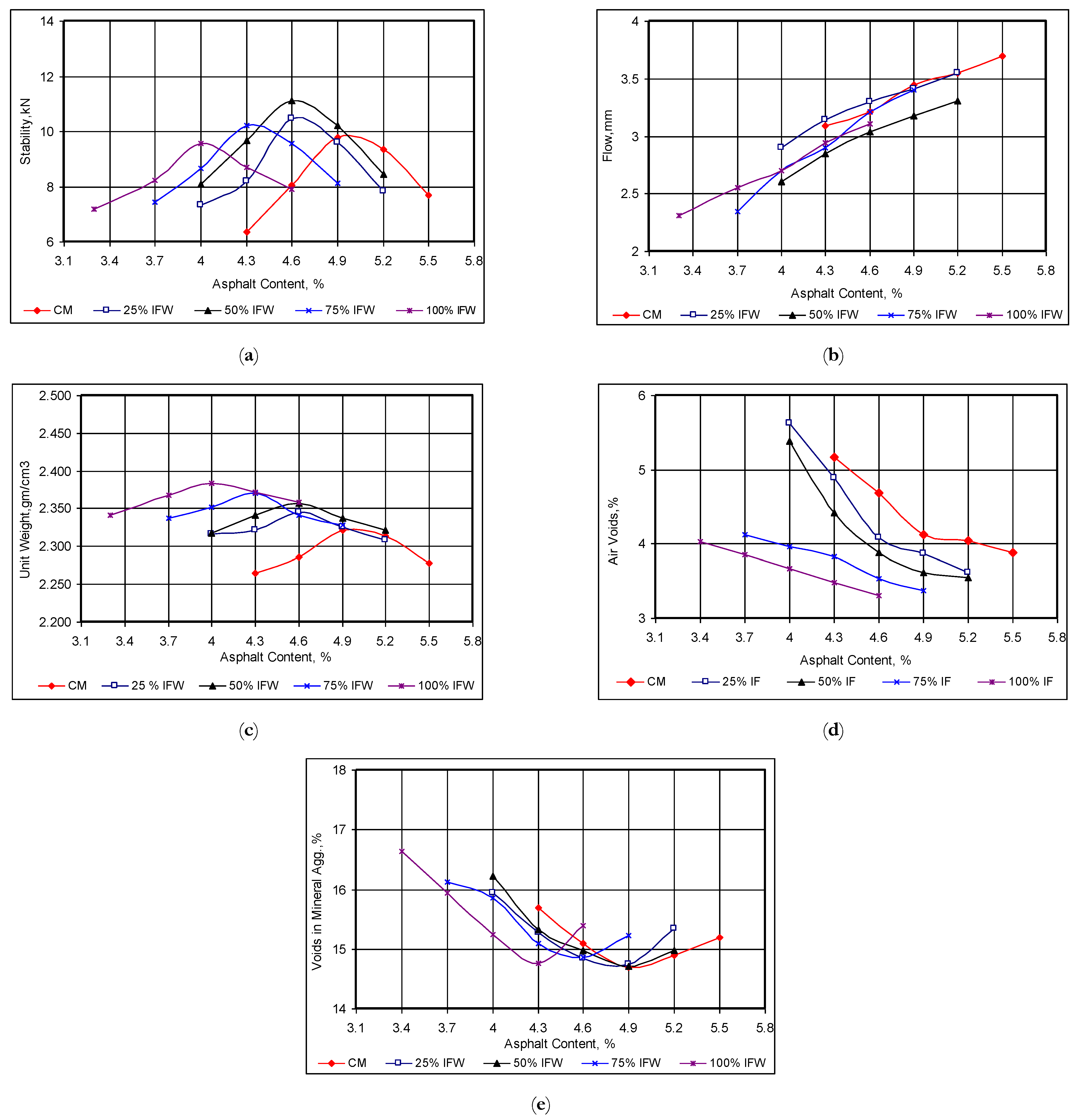
5.2. Marshall Properties

Figure 5 compares the Marshall test results for specimens created with different asphalt contents (ACs) and iron filing replacement rates. All the ACs fall in the range of the requirement limits specified in the SCRB. The results given in Figure 5a,c,d were used to determine the optimum asphalt contents (O.A.C.), which is the average value of the three ACs for the highest stability, highest bulk density, and 4% air voids (a median value specified [30]). It can be seen that when the IFW replacement increases from 0 to 50%, the Marshall properties display a considerable change; however, beyond a value of 50%, the influence on the Marshall properties reduces.
Table 5 lists the O.A.C. values for all five mixes investigated and their corresponding Marshall properties. It shows that the O.A.C. decreased from 5% for the control mix (0% IFW) to 3.8% for the 100% IFW mix. The O.A.C. stability increased from 9.5 kN for the control mix (CM) to the maximum value of 11.3 kN at a 50% IFW replacement rate. Thereafter, it started to drop gradually between the two IFW replacement rates of 75% and 100%. This result is in agreement with the work of Jendia and Tabash, who suggested an optimal IFW range of between 25 and 50% [18]. The increase in Marshall stability below a 50% IFW replacement rate is probably due to the high stiffness of the IFW particles and because of their smaller sizes, meaning that they tend to fill voids more effectively. However, it can be noticed that the increase in the IFW content did not have a significant effect on the air voids and or cause a decrease in the Marshall stability; this could be attributed to the amount of IFW, which is approximately unique-size fine materials unlike the FNS, as shown in the SEM images in Figure 4. The use of a higher replacement rate of FNS when using IFW will cause a reduction in the fine particle size variation and result in a decrease in the Marshall stability. Both the O.A.C. air voids (AV) and O.A.C. flow decreased with the increase in the IFW replacement rate, but all the AV values satisfied the specification range of 3–5%. The decrease in the AV and flow with the increase in the use of IFW can be explained to be due to the smoothness of iron filings. A low AV content may cause rutting, bleeding, and a loss of stability in asphalt concrete. The O.A.C. bulk density increased with the IFW content because of the higher density of IFW compared to the replaced natural sand [35,36].

5.3. Resilient Modulus (Mr)

Table 6 lists the Mr measurements obtained. It shows that the addition of IFW improves the Mr of the WMA concrete. The mixture made using IFW at a 50% replacement of FNS showed the optimal result, generating a 15.5% increase in Mr compared to the control mix.

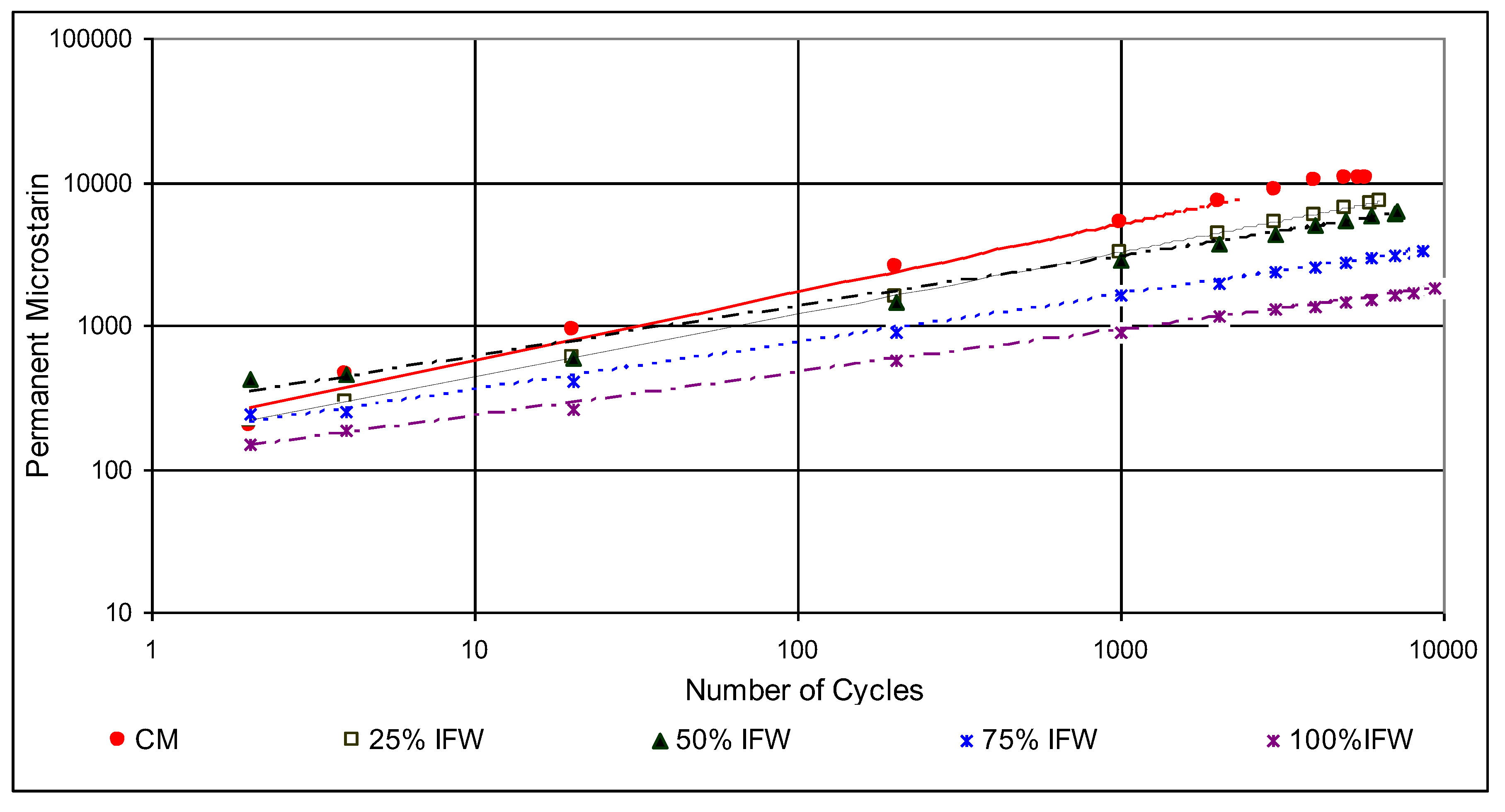
5.4. Permanent Deformation

Figure 6 shows the result of the permanent deformation test. It plots the measured permanent micro-strain against the cyclic axial loading applied to the cylindrical specimens until they failed. The plot is represented in the log-log scale [37], in which the relationship between the permanent deformation and the number of loading cycles presents a linear trend, and the two parameters—i.e., the intercept and slope—indicate the rutting resistance of the specimens. The smaller the two values are, the better the mixture rutting resistance will be. Additionally, the values of the two parameters obtained from Figure 6 are listed in Table 7. The result shows that the increase in IFW content caused a decrease in the rutting potential of the warm mix asphalt. This can mainly be attributed to the lower densification potential of the mixtures as the IFW increased because of the trend in air voids shown in Figure 5 and Table 5. The fewer air voids there are, the less densification occurs due to the load applied.

5.5. Durability Assessment

5.5.1. Moisture Susceptibility

Figure 7 compares the splitting tensile strength of conditioned and unconditioned specimens. One of the most remarkable points is that all WMA with an IFW addition presented a continuous improvement in indirect tensile strength (ITS) under dry conditions. The ITS value of the WMA modified with levels of 25%, 50%, 75%, and 100% IFW was increased by 9.5%, 24.2%, 28.4%, and 33.7%, respectively, compared with the control WMA. Furthermore, an interesting finding can be observed in that the TSR increased when the use rate of IFW rose. Consequently, the TSR values of the updated WMA with levels of 25%, 50%, 75%, and 100% IFW compared with the control WMA increased by 6.4%, 9%, 11.5%, and 12.8%, respectively. The use of 100% IFW achieved the greatest increase in the resistance to moisture in all the asphalt mixes. This may be because IFW contains small particles that have filled certain pores of asphalt specimens or prevented the penetration of water. On the other hand, the improvement in the TSR may be attributed to the hydrophobicity of steel fibers and the lack of water absorption. However, generally it may be observed that WMA blends with the addition of IFW were more efficient in terms of stripping resistance, while the control mixture containing 0% IFW showed an insufficient stripping resistance because the TSR was less than the minimum criterion of 80%. The laminar shape of the IFW described in Figure 4d caused the crack failure envelope, which resulted from the load applied across the diametrical plane of the specimen, to be longer than that of the FNS asphalt mixture samples with an angular particle geometry, and this resulted in the higher tensile strength ratio values shown in Figure 7 for all the replacement rates.

5.5.2. Flexural Fatigue

Figure 8 shows the fatigue test result. The relationship between the service life (the maximum number of load repetitions before failure) of all mixes and the initial tensile strain (determined by Equation (4)) showed a linear correlation in the log-log scale. The two parameters—i.e., the interception k1 and the slope k2—reflected the fatigue properties of these mixes. The lower the k1 was, the higher the capacity of the materials to resist the bending deformation was. On the other hand, the lower the k2 was, the higher the capacity of the specimen to resist fatigue failure was. The data shown in Table 8 demonstrate that the specimens with 25% and 50% IFW showed improvements in fatigue resistance of 8.6 and 19.4%, respectively, compared with the control mix. The average k1 value of the 50% IFW specimens—9.33E−11 compared with 1.72E−09 for the control specimens—also indicated an improvement in the bent deformation resistance. However, both k1 and k2 deteriorated when the IFW contents were 75% and 100%. This result indicates that the addition of 50% IFW optimized the effect of the high stiffness, angularity, and rough surface of IFW particles on the final properties of the asphalt concrete mix. Additionally, the use of a higher IFW content will result in a higher thermal conductivity as well as a higher temperature sensitivity in the mix, which will consequently have a negative influence on the fatigue properties of the WMA concrete.

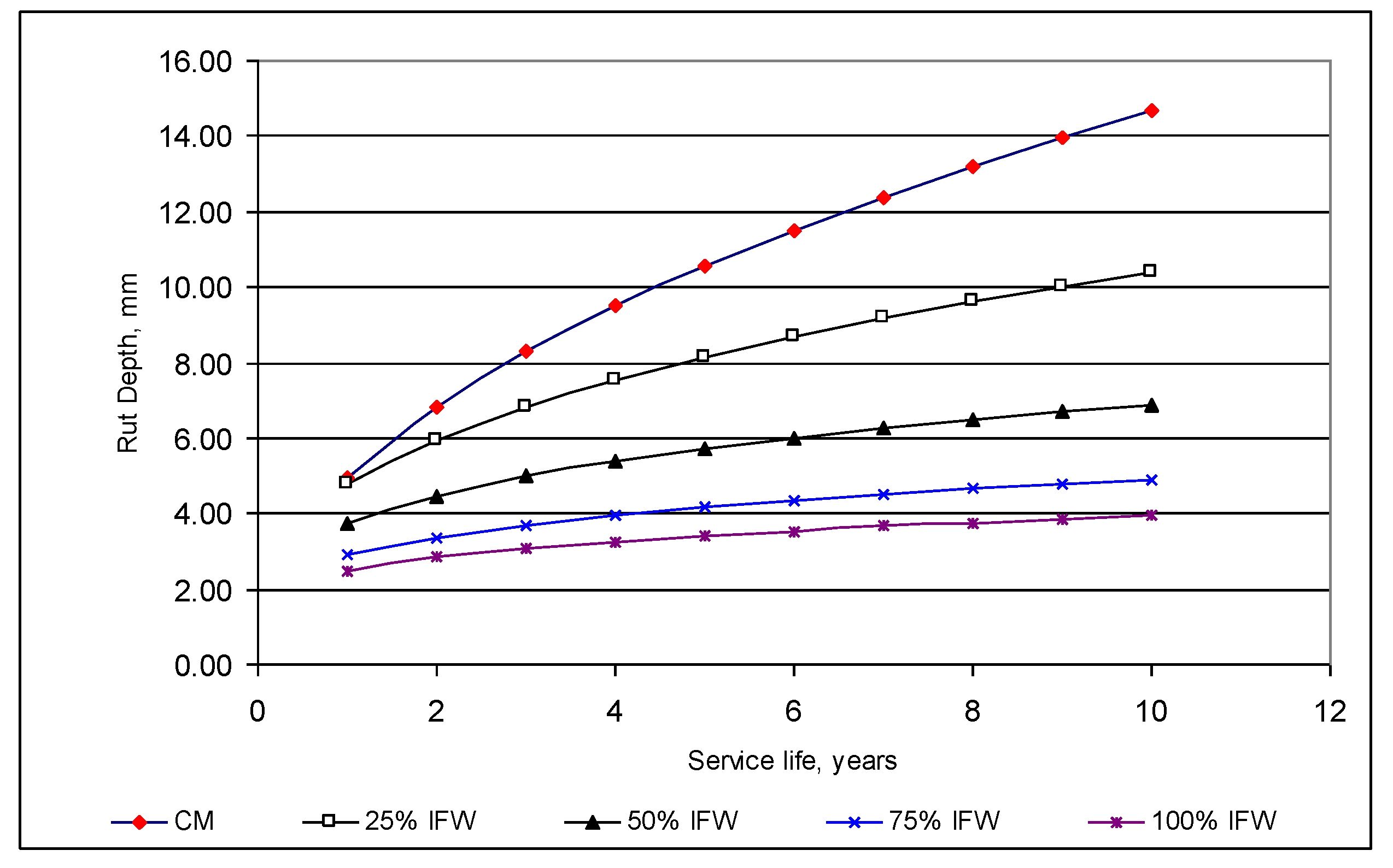
5.6. Performance Analysis Using VESYS 5 W Software

VESYS software was employed to evaluate the performance of the pavement throughout the study period. VESYS is regarded as a viable rutting prediction method that can be utilized to evaluate the rutting performance of paving constructions through multiple permanent deformation approaches [38]. Based on both probabilistic as well as mechanistic analyses, VESYS consists of two rutting models—i.e., system rutting and layer rutting. The system rutting model considers the whole pavement structure in terms of the permanent deformation characterization on experimental data. The characterization law represents the correlation between the permanent strain of asphalt concrete and cyclic loading in terms of Equation (5):
Δ ε p   ( N ) ε = μ N α  
where Δ ε p(N) is the vertical permanent strain at N load repetitions; ε is the peak haversine load strain under a load pulse of 0.1 s duration; and at the 200th repetition, the μ and α are two material parameters that depend on the stress state, temperature, etc. The layer rutting model is used to evaluate the permanent deformation of each finite layer in terms of both the elastic and permanent deformation of the specific layer. The layer rutting model is expressed in the form of Equation (6):
R D = N 1 N 2 U s   +   e 1 e s   μ s u b   N α s u b   +   550 i = 1   N 1 N 2 ( U i + U i ) μ i   N α i
where the deflection at the top of the subgrade is represented by U s , which is formed by a single axle load; U i + and U i indicate the deflection at the top and bottom of layer i, which is formed by the axle group; et is the strain at the top of subgrade formed by the axle group; μsub and αsub show the permanent deformation of the subgrade; and μi and αi show the permanent deformation parameters of layer i. Using least squared regression analysis, the model computes the permanent deformation parameters—i.e., αsys and μsys. The surface rut depth is determined accordingly as follows:
R D   = N 1 N 2 U μ   s y s   N α s y s   d N
where U is the pavement surface deflection.
As an illustrative case study, the load of traffic is 3.65 × 10⁶ for ESAL (equivalent single axle loads) over a 10-year study period, or 365 × 103 each year, with a 551 kPa (80 psi) tire inflation pressure as well as a 11.49 mm (4.35 in) contact radius. For rutting, μ and α are the input parameters, α is the rate of reduction in the permanent deformation with the increasing level of load application (1-slope), and μ is the constant rate of proportionality between the resilient (elastic) and permanent strain ((intercept × slope) = resilient strain). For the fatigue cracking input parameters, the input software values are k1 and k2, which were previously given in Table 9.
Rutting in flexible pavements progressively occurs with higher load applications. It is produced by a combination of densification (diminution in volume and thus increase in density) and shear deformation. The rutting, as per AASHTO [39], is graded in three levels according to its severity: low (0–13 mm), medium (13–25 mm), and severe (above 25 mm).
Figure 9 shows the VESYS result. All the IFW concrete pavements showed a lower level of rutting, compared with that of the control mix, up to 10 years of service life. The result shown in Figure 9 suggests that the use of IFW may be up to a level of 100%, or it may fully replace all of the NFS.
VESYS predicts the fatigue cracking to yield a crack index (CI). CI is a dimensionless metric parameter that estimates the degree of fatigue cracking on the surface of the pavement. The IC at the bottom of the lowest asphalt layer is given as a value below 1. An IC value of between 1 and 1.5 suggests a slight cracking fatigue on the surface of the pavement. A value in the range of 1.5–2.5 reflects moderate fatigue cracking, while a value in the range of 2.5–3.5 implies severe surface cracking. Figure 10 shows the CI values after the end of the design service life. It shows that the use of IFW in general reduces fatigue cracking after the design service life has ended. However, the concrete with 50% IFW demonstrated the best performance in terms of fatigue cracking resistance.
In summary, the investigation carried out using the VESYS 5W and the experimental data from this study suggest that the use of IFW to replace FNS in a proportion of up to 100% can be considered for improving rutting resistance for pavement construction in hot climatic regions, while the use of 50% replacement can be considered for improving fatigue resistance for pavement construction in cold regions.

6. Conclusions

This research reports an evaluation of the properties of WMA using IFW as an alternative fine aggregate at four contents—i.e., 25%, 50%, 75%, and 100%—of the total aggregate weight. The following conclusions can be drawn from this study:
  • For WMA concrete, the use of 25–50% IFW increased the Marshall stability by 13.7–18.9%.
  • IFW has a substantial impact on the volumetric properties of WMA, the air void concentration, and the number of voids in mineral aggregate.
  • In general, the use of IFW causes a considerable decrease in the rutting depth and fatigue cracking. The use of 50% IFW results in a significant improvement in the fatigue life of WMA concrete under repetitive loading. However, the use of more than 50% IFW will deteriorate the fatigue resistance of the WMA concrete.
  • The addition of IFW improves the durability of WMA pavement by increasing both the tensile strength ratio and the fatigue resistance under the condition of wet exposure.
  • Finally, this study indicates that the use of a 50% replacement of natural sand in IFW causes a significant improvement in the performance of warm mix asphalt concrete. This research has provided valuable knowledge regarding the ability to produce more durable warm-mix asphalt with a superior resistance to moisture damage, rutting, and the mode of fatigue failure that is most encountered in asphalt pavement in variable climate conditions.

Author Contributions

Conceptualization, A.A.; methodology, A.A.; software, A.A.; validation, Y.W.; formal analysis, H.A.-M.; investigation, J.H.; resources, H.K.M.; data curation, R.H.L.; writing—original draft preparation, R.H.L.; writing—review and editing, Y.W., J.H. and A.A.; visualization, H.A.-M.; supervision, A.A.; project administration, H.K.M. All authors have read and agreed to the published version of the manuscript.

Funding

This research received no external funding.

Institutional Review Board Statement

Not applicable.

Informed Consent Statement

Not applicable.

Conflicts of Interest

The authors declare no conflict of interest.

References

  1. Cremiato, R.; Mastellone, M.L.; Tagliaferri, C.; Zaccariello, L.; Lettieri, P. Environmental impact of municipal solid waste management using Life Cycle Assessment: The effect of anaerobic digestion, materials recovery and secondary fuels production. Renew. Energy 2018, 124, 180–188. [Google Scholar] [CrossRef] [Green Version]
  2. Kuhlman, T.; Farrington, J. What is Sustainability? Sustainability 2010, 2, 3436–3448. [Google Scholar] [CrossRef] [Green Version]
  3. Aziz, M.A.; Rahman, T.; Hainin, M.R.; Abu Bakar, W.A.W. An overview on alternative binders for flexible pavement. Constr. Build. Mater. 2015, 84, 315–319. [Google Scholar] [CrossRef]
  4. Nedeljković, M.; Visser, J.; Valcke, S.; Schlangen, E. Physical Characterization of Dutch Fine Recycled Concrete Aggregates: A Comparative Study. Proceedings 2019, 34, 7. [Google Scholar] [CrossRef] [Green Version]
  5. Gallego, J.; Del Val, M.A.; Contreras, V.; Páez, A. Use of additives to improve the capacity of bituminous mixtures to be heated by means of microwaves. Mater. Construcción 2017, 67, 110. [Google Scholar] [CrossRef] [Green Version]
  6. Latief, R.H. Evaluation of the Performance of Glasphalt Concrete Mixtures for Binder Course. Int. J. Adv. Sci. Eng. Inf. Technol. 2019, 9, 1251–1259. [Google Scholar] [CrossRef]
  7. Albayati, A.; Wang, Y.; Wang, Y.; Haynes, J. A sustainable pavement concrete using warm mix asphalt and hydrated lime treated recycled concrete aggregates. Sustain. Mater. Technol. 2018, 18, e00081. [Google Scholar] [CrossRef]
  8. Silvestre, R.; Medel, E.; Garcia, A.; Navas, J. Using ceramic wastes from tile industry as a partial substitute of natural aggregates in hot mix asphalt binder courses. Constr. Build. Mater. 2013, 45, 115–122. [Google Scholar] [CrossRef] [Green Version]
  9. Esther, L.-A.; Pedro, L.-G.; Irune, I.-V.; Gerardo, F. Comprehensive analysis of the environmental impact of electric arc furnace steel slag on asphalt mixtures. J. Clean. Prod. 2020, 275, 123121. [Google Scholar] [CrossRef]
  10. Liu, W.; Li, H.; Zhu, H.; Xu, P. The Interfacial Adhesion Performance and Mechanism of a Modified Asphalt–Steel Slag Aggregate. Materials 2020, 13, 1180. [Google Scholar] [CrossRef] [Green Version]
  11. Swathi, M.; Andiyappan, T.; Guduru, G.; Reddy, M.A.; Kuna, K.K. Design of asphalt mixes with steel slag aggregates using the Bailey method of gradation selection. Constr. Build. Mater. 2021, 279, 122426. [Google Scholar] [CrossRef]
  12. Alnadish, A.M.; Aman, M.Y.; Katman, H.Y.B.; Ibrahim, M.R. Laboratory assessment of the performance and elastic behavior of asphalt mixtures containing steel slag aggregate and synthetic fibers. Int. J. Pavement Res. Technol. 2021, 14, 473–481. [Google Scholar] [CrossRef]
  13. Mo, L.; Yang, S.; Huang, B.; Xu, L.; Feng, S.; Deng, M. Preparation, microstructure and property of carbonated artificial steel slag aggregate used in concrete. Cem. Concr. Compos. 2020, 113, 103715. [Google Scholar] [CrossRef]
  14. Ali, A.H.; Abbas, A.S. Effect of Using Recycled Local Solid Waste Materials On Creep Properties of Asphalt Mixtures. Al-Nahrain J. Eng. Sci. 2011, 14, 122–136. [Google Scholar]
  15. Cheraghian, G.; Wistuba, M.P.; Kiani, S.; Barron, A.R.; Behnood, A. Rheological, physicochemical, and microstruc-tural properties of asphalt binder modified by fumed silica nanoparticles. Sci. Rep. 2021, 11, 1–20. [Google Scholar]
  16. Cheraghian, G.; Falchetto, A.C.; You, Z.; Chen, S.; Kim, Y.S.; Westerhoff, J.; Wistuba, M.P. Warm mix asphalt tech-nology: An up to date review. J. Clean. Prod. 2020, 268, 122128. [Google Scholar] [CrossRef]
  17. Rasool, D.A.; Abdulkarem, M.A.; Abdulrehman, M.A. The Effect of Adding Recycled Waste on the Mechanical Properties of Concrete. Defect Diffus. Forum 2020, 398, 83–89. [Google Scholar] [CrossRef]
  18. Attom, M.; Kou, M.; Al-Akhras, N. Geo environmental utilization of iron-filing with cement in soil stabilization. Int. J. Technol. Eng. Stud. 2016, 2, 32–37. [Google Scholar]
  19. Franesqui, M.A.; Yepes, J.; González, C.G. Top-down cracking self-healing of asphalt pavements with steel filler from industrial waste applying microwaves. Constr. Build. Mater. 2017, 149, 612–620. [Google Scholar] [CrossRef]
  20. Abdalqadir, Z.K.; Salih, N.B.; Salih, S.J.H. Using Steel Slag for Stabilizing Clayey Soil in Sulaimani City-Iraq. J. Eng. 2020, 26, 145–157. [Google Scholar] [CrossRef]
  21. Arabani, M.; Mirabdolazimi, S. Experimental investigation of the fatigue behaviour of asphalt concrete mixtures containing waste iron powder. Mater. Sci. Eng. A 2011, 528, 3866–3870. [Google Scholar] [CrossRef]
  22. Tabash, O. Study the Effect of Crushed Waste Iron Powder as Coarse Sand and Filler in the Asphalt Binder Course. Master’s Thesis, Islamic University, Gaza, Palestine, 2014. [Google Scholar]
  23. Alakhrass, M.S. The Effect of Adding Iron Powder on Self-Healing Properties of Asphalt Mixture. Master’s Thesis, Islamic University of Gaza, Gaza, Palastine, July 2013. [Google Scholar]
  24. Khliefat, I.; Msallam, M. Modification of asphalt mixes using white cement dust and iron filings as a filler. Elektron. Časopis Građevinskog Fak. Osijek 2021, 11, 67–77. [Google Scholar] [CrossRef]
  25. Mohammed, S.I. University of Duhok Effect of Using Waste Iron Powder As Filler on Asphalt Mixture Properties. J. Univ. Duhok 2021, 24, 10–18. [Google Scholar] [CrossRef]
  26. Eisa, M.S. Improving Asphalt Mix Properties Using Iron Filings A Mineral Filler. In Proceedings of the 2nd International Conference on Innovative Building Materials, Cairo, Egypt, 2–4 December 2018; Volume 87, pp. 1119–1128. [Google Scholar]
  27. Ahlrich, R.C. Marginal Aggregates in Flexible Pavements: Field Evaluation; No. DOT/FAA/AR-97/5; William J. Hughes Technical Center (US): Egg Harbor Township, NJ, USA, 1998. [Google Scholar]
  28. Zaniewski, J.P.; Srinivasan, G. Evaluation of Indirect Tensile Strength to Identify Asphalt Concrete Rutting Potential; Asphalt Technology Program, Department of Civil and Environmental Engineering, West Virginia University, Performed in Cooperation with the US Department of Transportation-Federal Highway Administration: Ashburn, VA, USA, 2004. [Google Scholar]
  29. Albayati, A.H.; Abdulsattar, H. Performance evaluation of asphalt concrete mixes under varying replacement percentages of natural sand. Results Eng. 2020, 7, 100131. [Google Scholar] [CrossRef]
  30. SCRB. Standard Specification for Roads and Bridges (Section R/9), revised ed.; State Commission of Roads and Bridges, Ministry of Housing and Construction: Baghdad, Iraq, 2003. [Google Scholar]
  31. ASTM D6926-20. Standard Practice for Preparation of Asphalt Mixture Specimens Using Marshall Apparatus; ASTM International: West Conshohocken, PA, USA, 2020. [Google Scholar]
  32. AI. Thickness Design—Asphalt Pavements for Highways and Streets (No. 1); Manual Series No. 1; Asphalt Institute: College Park, MD, USA, 1981. [Google Scholar]
  33. Albayati, A.H. Permanent Deformation Prediction of Asphalt Concrete Under Repeated Loading. Ph.D. Thesis, University of Baghdad, Baghdad, Iraq, 2006. [Google Scholar]
  34. ASTM D4867/D4867M-09. Standard Test Method for Effect of Moisture on Asphalt Concrete Paving Mixtures; ASTM International: West Conshohocken, PA, USA, 2014. [Google Scholar]
  35. Wajde, L.M.R.M.; Zainab, S.S.A.; Rasoul, M.R.A.; Abdulrasool, A.T. Utilization Iron Filings and Microwave Heating in Roughening the Surface of Smoothed Coarse Aggregates. Int. J. Eng. Technol. 2018, 7, 395–398. [Google Scholar] [CrossRef] [Green Version]
  36. Idan, M.F. Study of the Modify of Mechanical Behaviour of Concrete. J. Eng. Appl. Sci. 2020, 15, 1698–1702. [Google Scholar] [CrossRef] [Green Version]
  37. Monismith, C.L.; Ogawa, N.; Freeme, C. Permanent deformation characteristics of subgrade soils due to repeated loading. Transport. Res. Rec. 1975, 537. [Google Scholar]
  38. Zhou, F.; Fernando, E.; Scullion, T. A Review of Performance Models and Test Procedures with Recommendations for Use in the Texas M-E Design Program; Technical Report; Texas Transportation Institue, The Texas A&M University: College Station, TX, USA, 2008. [Google Scholar]
  39. AASHTO. AASHTO Guide for Design of Pavement Structures; AASHTO: Washington, DC, USA, 1993; Volume 1. [Google Scholar]
Figure 1. Aggregate grading for wearing layer.
Sustainability 13 13828 g001
Figure 2. The iron filings and FNS.
Sustainability 13 13828 g002
Figure 3. Viscosity–temperature chart of PG 64-16.
Sustainability 13 13828 g003
Figure 4. SEM images of the FNS and IFW. (a) FNS, 0.5 kx, (b) IFW, 0.5 kx, (c) FNS, 5 kx, (d) IFW, 5 kx.
Sustainability 13 13828 g004
Figure 5. Marshall properties. (a) Stability, (b) Flow, (c) Unit weight, (d) Air voids, (e) Voids in mineral aggregate.
Sustainability 13 13828 g005
Figure 6. Permanent microstrain vs. load repetition.
Sustainability 13 13828 g006
Figure 7. Results of the indirect tensile test.
Sustainability 13 13828 g007
Figure 8. Fatigue test results.
Sustainability 13 13828 g008
Figure 9. The predicted rut depth over the design service life for the CM and IFW blends.
Sustainability 13 13828 g009
Figure 10. Cracking index for the CM and IFW blends.
Sustainability 13 13828 g010
Table 1. Experimental results and specification limits for asphalt cement.
BinderPropertyMeasurement Temperature
°C
Specification
AASHTO M320-05
OriginalFlash Point (°C)298-230 °C, min.
Viscosity at 135 °C (Pa·s)0.487-3 Pa·s, max.
DSR, G/sinδ at 10 rad/s (kPa)3.3522581.00 kPa, min.
2.02064
0.88970
RTFO AgedMass Loss (%)0.654-1%, max.
DSR, G/sinδ at 10 rad/s (kPa)4.1596582.2 kPa, min.
3.148364
1.980970
PAV AgedDSR, G.sinδ at 10 rad/s (kPa)4684285000 kPa, max.
647725
BBR, Creep Stiffness (MPa)134.0−16300, max.
Table 2. Coarse and fine aggregates: physical properties.
PropertyASTM DesignTest OutcomesSpecification of SCRB [30]
Coarse Aggregate
Apparent Specific GravityC-1272.636-
Bulk Specific Gravity2.632-
Water Absorption (%)0.261-
Soundness (sodium sulfate solution loss) (%)C-884.312 max.
Percent Wear (Los Angeles abrasion) (%)C-1311830 max.
Flat and Elongated (5:1) (%)D4791410 max.
Fractured Pieces (%)D58219790 min.
Fine Aggregate
Apparent Specific GravityC-1282.622-
Bulk Specific Gravity2.561-
Water Absorption (%)0.809-
Clay Lump and Friable Particles (%)C-1421.23 max.
Sand Equivalent (%)D24195945 min.
Table 3. Mineral filler’s chemical composition and physical properties.
Chemical Composition (%)
L.O.ISO3Fe2O3MgOAl2O3SiO2CaO
370.1211661029
Physical Properties
Specific GravitySurface Area * (m2/kg)Passing Sieve No. 200 (0.075) (%)
2.8424795
* Blain air permeability technique (ASTM C204).
Table 4. Physical properties and chemical composition of aspha-min additive.
Chemical Composition (%)
SiO232.8
Al2O329.1
Na2O16.1
L.O.21.2
Physical Properties
Specific Gravity2.03
OdorOdorless
ColorWhite
Table 5. O.A.C. with IFW percentages.
IFW
(%)
O.A.C. (%)Stability
(kN)
Flow
(mm)
Air Voids
(%)
VMA
(%)
Bulk Density
(gm/cm3)
059.53.54.1014.72.320
254.6210.83.34.0514.82.340
504.611.33.13.8015.02.360
754.179.52.753.8015.42.365
1003.88.82.653.7015.62.375
Specification Limits [23]3–68 min.2–43–514 min.Not Limited
Table 6. Resilient modulus results.
IFW Content, %0 255075100
Resilient Modulus, MPa21982309253925092488
Table 7. Permanent deformation parameters.
IFW Content (%)0255075100
Intercept193159269165117
Slope0.4740.43510.34760.32870.2969
Table 8. Fatigue parameters.
IFW Content (%)0255075100
k11.72E−099.49E−109.33E−111.29E−086.91E−08
k23.153.423.763.092.87
Table 9. The result of the moisture susceptibility test.
MixtureITS (Dry) kPaITS (Wet), kPaTSR %
CM94673878
25% IFW104185482
50% IFW1177100085
75% IFW1215104586
100% IFW1268110387
Publisher’s Note: MDPI stays neutral with regard to jurisdictional claims in published maps and institutional affiliations.

