Abstract
In the present paper, an integrated intervention system applicable to concrete-framed buildings is presented. The purpose of the intervention is to improve both the seismic and the energetic behaviour of such buildings using cross-laminated timber (CLT) panels. Two alternative intervention configurations with different levels of invasiveness are described. Considering a double-wythe masonry-infilled frame, the most invasive configuration consists in the replacement of the external masonry wythe with the CLT panel, while the least invasive configuration consists in the arrangement of the CLT panel from the outside without removing the wythes. The technical details and implementation procedures were studied, considering functionality and disturbance to occupants. An isolated one-storey-one-bay frame was used as a reference for the seismic and thermal analyses. Subsequently, the two intervention configurations were applied to a case-study building by identifying two alternative intervention strategies. The obtained results showed that the proposed integrated intervention approach can significantly reduce both the seismic vulnerability and the energy consumption of concrete buildings.
1. Introduction
Over the last decades, the construction codes of many countries have paid continually increasing attention to the energy consumption and the seismic behaviour of new buildings. However, built heritage is often characterised by details and construction techniques that deviate significantly from that required for new structures, regarding both energetic and the seismic aspects thereof. Additionally, from the second half of the 20th century onward, an excessive expansion of built-up areas has threatened natural ecosystems [1]. Therefore, the urge for sustainable development has brought many countries to limit new construction, while promoting building retrofitting, rehabilitation, and renovation.
According to the reports of the European Commission [2], approximately 36% of the greenhouse gas emissions and 40% of energy consumption in the European Union are building-related. Furthermore, almost 75% of the building stock is considered energy inefficient [3]. Most of the existing buildings, especially the residential ones, not only feature outdated services, but also have either no insulation or present several thermal bridges. This inefficiency also affects comfort and wellbeing of the occupants, as reported in the 2009 World Health Organisation guidelines [4].
Improving the energy performance of buildings is essential for reducing operating costs and has a fundamental role in the decarbonisation process. According to Pombo et al. [5], who provide an overview of existing housing renovation strategies, three energy efficiency measures are possible: the improvement of the building service systems, the implementation of renewable energy, and the retrofitting of the building envelope. In particular, the present study focuses on the latter, taking the contribution of the other two measures also into account. The refurbishment of existing buildings can bring relevant energy savings, with a decrease in the EU’s total energy demand by 5–6% and in CO2 emissions by approximately 5% [3].
In many areas of the world, earthquakes constitute a severe source of hazard and therefore must be carefully dealt with in order to prevent the loss of human lives, cultural heritage, and economic value. Recent earthquakes (e.g., centre of Italy, 2016 and 2017; Greece, 2020; Petrinja, 2020) have shown that past construction practices often lead to damage or collapse under seismic actions of smaller magnitude than those considered for new buildings. In addition, with reference to reinforced concrete (RC)- framed buildings, the interactions between structural and non-structural elements may induce dangerous phenomena such as the overturning of the masonry infills, shear failures of the columns, or the activation of soft storey mechanisms [6,7]. These phenomena depend on various factors [8,9,10] such as the properties of the materials, the geometry of elements, or the infills distribution both in elevation and in plan.
In this scenario, the interest in developing new solutions to improve both the seismic and energetic behaviours of existing buildings is expanding among the scientific community [11,12,13,14,15,16]. However, trying to reduce energetic and seismic vulnerabilities by relying on completely independent strategies could entail high costs and conflicting processes. For example, the application of structural interventions can generate additional thermal bridges while, at the same time, energy interventions can modify the seismic response of the structure. Consequently, to deal efficiently with such issues, renovation actions need to be combined. Improving energy efficiency and seismic safety at the same time, via integrated approaches, can indeed minimise conflicting processes, implementation time, and processing costs.
In the last few years, several integrated retrofit solutions that included different materials and techniques have been studied all over the world. For example, integrated solutions based on the use of independent multi-purpose exoskeletons [17,18], timber prefabricated panels [19], or autoclaved aerated concrete blocks [20] have been proposed.
In the present article, an integrated solution, applicable to masonry-infilled RC framed buildings, is presented, consisting of the use of prefabricated timber panels adequately fixed to the existing structure. The proposed solution is expected to improve the in-plane and out-of-plane seismic response of the building’s frame, thus reducing the overall seismic vulnerability of the building and providing external insulation of its envelope. Specifically, two intervention configurations that differ in the invasiveness of their implementation have been developed. In the least invasive configuration, the panel is applied to the external side of the structural frame without removing the existing infill wall. This system is named “RC–TPext” (reinforced concrete–external timber panels). In the most invasive configuration instead, the CLT panel is placed inside the structural frame, after removing one or both wythes of the existing masonry infill. This system is named “RC–TP” (reinforced concrete–timber panels) and it has been deeply investigated [21,22,23]. The adoption of the RC–TPext configuration means shorter execution time and less disturbance to the occupants. On the other hand, RC–TP has a greater impact on the building, even though it results in reduced wall thickness. In addition, because the structural panels are placed inside the concrete frames, RC–TP can provide additional resistance for vertical forces in case of severe damage to the structural concrete elements.
In the current paper, functioning principles and technical details of the two intervention configurations are presented, showing significant seismic and energetic benefits with reference to a generic RC frame. In order to investigate the energy performance improvements obtained from the retrofit intervention at a wider level, the two systems were applied to a five-storey case-study building.
2. Retrofit Solution
The proposed integrated retrofit solution entails the building envelope and aims to reduce: (a) the seismic vulnerability of concrete structures by preventing brittle mechanisms and favouring a ductile behaviour; (b) the energy consumption during the service life of the building. The proposed solution implies the installation of structural cross-laminated timber (CLT) panels that are connected to the RC elements through steel connectors. During the development of the proposed system, attention was paid to occupants’ disturbance. Indeed, starting from a typical masonry infilled frame, two intervention configurations characterized by different levels of invasiveness are presented. In particular, a double wythe masonry infill was assumed for the as-built configuration (Figure 1a), as it was considered representative of most of the existing RC framed buildings. In the most invasive configuration, named RC–TP (reinforced concrete–timber panels), the CLT panel is inserted in the RC frame by replacing the external wythe of the infill (Figure 1b), while in the least invasive configuration, RC–TPext (reinforced concrete–external timber panels), the CLT panel is installed from the outside without removing the masonry infill (Figure 1c). The intervention configurations are provided with insulating layers, placed on the inner side of the timber panel and on the outer side as well. The proposed insulating materials were designed to obtain optimal moisture and thermal responses, both in summer and in winter, thus granting good indoor comfort for the building’s occupants.
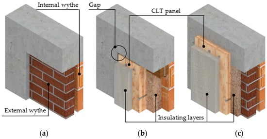
Figure 1.
Pre- and post-intervention systems: (a) as-built masonry-infilled configuration; (b) RC–TP configuration; (c) RC–TPext configuration.
Regarding the seismic response, the main goal of the two proposed intervention configurations is to reduce the vulnerabilities that ensue from the interactions between the RC elements and the masonry infills. When considering the in-plane behaviour of the frames, both intervention configurations aim to avoid the development of brittle mechanisms (i.e., shear failures of the concrete elements due to interaction with the masonry infill). Concerning the out-of-plane behaviour, RC–TP and RC–TPext are meant to prevent the overturning of the infill, which is fixed to the CLT panel that, in turn, acts as a support.
2.1. Existing Structural Frame
To examine, in detail, the presented system, reference was made to a generic masonry-infilled RC frame that can be considered representative of the ‘70 s–80 s’ RC framed buildings in Southern Europe [24,25,26,27]. The geometry of the frame, its reinforcement details, and its loading conditions (Table 1 and Figure 2) are consistent with those reported in [28].

Table 1.
Characteristics of the structural frame.
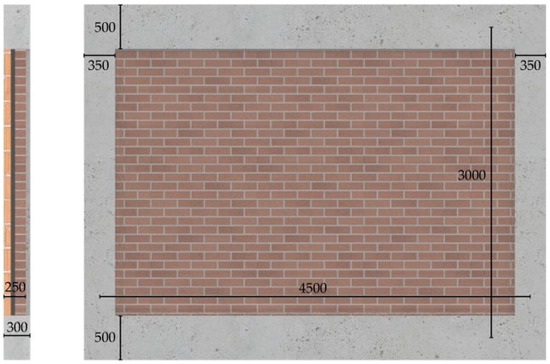
Figure 2.
Existing structural frame with double-wythe masonry infill.
Mechanical properties of concrete, steel, and masonry elements are derived from [24,29,30,31,32] and are reported in Table 2 and Table 3.
Table 2.
Material properties of the structural frame.
Table 3.
Material properties of the double wythe masonry infill.
2.2. RC–TP Configuration
In the RC–TP configuration, the CLT panel is inserted into the RC frame and fixed to it through a timber subframe. This configuration has been extensively discussed in [21,22,23], where RC frames infilled with single-wythe masonry were retrofitted and analysed under nonlinear static in-plane loading. In the cited studies, therefore, the intervention consisted in the complete replacement of the infills with CLT panels. The frame considered in the present paper, instead, presents a double-wythe masonry infill. The results reported in the following sections show that the internal wythe (made of hollow bricks) is neither stiff nor strong enough to engage the shear failure of the concrete elements when the system is subjected to horizontal loading. Consequently, to limit the invasiveness of the intervention, only the strong external wythe was removed and replaced with a CLT panel, to which the remaining internal wythe must be connected to prevent its out-of-plane collapse. Due to the presence of hollow bricks, approximately five adhesive anchors per square meter should be used to connect the panel to the infill. The anchors are made of 12 mm threaded steel rods bonded to bricks by using epoxy-based resin.
Based on the recommendations provided by [23], for the load and geometrical characteristics of the selected frame, the RC–TP solution was implemented by arranging the timber subframe only along the beams. In order to avoid any concentration of shear stress due to the direct contact between the CLT panel and the RC frame, a gap of 2 cm of size was created at the perimeter of the CLT panel between the timber surface and the concrete surface. This gap is also necessary for the insertion of the panel into the frame. The subframe, of size 12 × 12 cm, was fixed to the RC elements through 12-mm concrete screws, forming a connection designed to remain in the elastic range for design-intensity earthquakes. The connection between the CLT panel and the subframe has, instead, a dissipative function and consists of 10-mm timber screws spaced at 10 cm intervals.
Furthermore, because the panel is placed inside the frame, the fibres of the odd CLT layers are oriented along the vertical axis to provide additional resistance to vertical loads. Such resistance is activated in case the seismic action markedly aggravates the vertical loads or damages the RC frame elements. For this reason, in order to grant the capacity of the system to contribute resistance, also, to vertical actions, a three-layered 10-cm CLT panel was assumed. It is worth noting that, in the previous studies, a panel thickness of six centimetres has been proved sufficient to generate significant improvements in the in-plane behaviour of the frame.
A 12-cm internal insulating layer made of wood fibres fills the internal cavity between the brick masonry and the CLT panel. On the outer side of the panel, there is a continuous insulation layer of polyurethane 6-cm thick. Both materials were selected with consideration of their thermal properties and their granted fire protection.
The layup of the RC–TP configuration is reported in Figure 3.
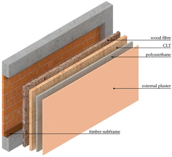
Figure 3.
RC–TP configuration layers.
The timber subframe was made of glued laminated timber from grade class GL 24 h [33], while the CLT panel was made of boards of grade class C24 according to [34].
2.3. RC–TPext Configuration
The RC–TPext configuration (Figure 4) permits maintaining the existing masonry infills entirely and is characterised by shorter execution time and less occupant disturbance as compared with RC–TP.
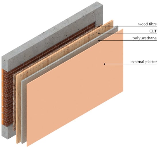
Figure 4.
RC–TPext configuration layers.
As the external masonry wythe is assumed to be strong, the RC–TPext configuration requires this wythe to be disconnected from the RC columns, leaving a gap of at least 3 cm. Such gap prevents the infill from transmitting additional shear stress to the columns during in-plane seismic oscillations. As mentioned before, the internal weak wythe lacks the stiffness and the strength to cause damage to the columns. Therefore, it is not required to disconnect the internal wythe from the RC elements.
To prevent the overturning of the infill under seismic out-of-plane loading, the two masonry wythes must first be connected to each other and then to the CLT panel. Due to the presence of the hollow bricks, adhesive anchors (e.g., epoxy bonded anchors with nylon/plastic sleeves to favour the resin injection) are recommended for the connection between the masonry wythes, while dry screw anchors can be used for the connection between the solid bricks and the CLT panel. Similar to the RC–TP configuration, approximately five 12-mm anchors per square meter should be used.
For RC–TPext configuration, a three-layer 6-cm thick CLT panel was connected to the concrete beams using 12-mm concrete screws spaced 15 cm apart, which have a dissipative function. As the panel is arranged outside the frame, the RC–TPext configuration is not designed to contribute to resisting vertical actions.
A 5-cm insulating layer made of wood-fibre panels fills the cavity between brick masonry and CLT panel. Continuous insulation made of 6-cm polyurethane is applied to the outer surface of the panel in the RC–TP configuration.
2.4. Durability
The use of timber elements requires specific precautions in order to avoid direct contact with water accumulation, which can cause severe degradation of the material. Designs should cover all conditions that can reasonably be expected during the construction and use of the structure [35], including rain infiltration, indoor vapour production, or possible pipe leaks. A constructive detail for the two intervention configurations is proposed. Particular attention was paid to avoiding contact between the timber and the concrete beam, through which water, coming from the subfloor, could flow (Figure 5). Water coming from the outside can be deviated with the correct design of junctions and flashings.
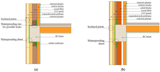
Figure 5.
Precautions to avoid water accumulation by the timber elements: (a) RC–TP; (b) RC–TPext.
2.5. Execution
In order to speed up execution, the proposed retrofit solution can be partially prefabricated by bonding the CLT panel with the inner and outer insulating layer in the factory, reducing labour and implementation time. In the external insulating layer, a space should be left for the application of the steel connectors that would later be filled and sealed with insulating foam. Specifically, holes in the insulating layer are made for the insertion of the CLT-masonry fasteners (both for RC–TP and RC–TPext), while a ~10-cm strip of uncovered CLT is left at the top and bottom edges of the panel for installing the CLT-concrete (RC–TPext) or CLT-subframe (RC–TP) connections.
The panels, which are of considerable size, should be moved using a crane. This implies that execution has to start from the building base; the scaffolding is assembled one floor at a time, moving to the next level when the application of the prefabricated panels at the previous level is complete. Subsequent operations can be performed standing on the scaffolding. The representations of the assembly of RC–TP and RC–TPext are reported in Figure 6 and Figure 7, respectively.
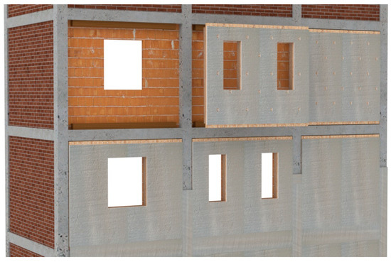
Figure 6.
RC–TP assembly.
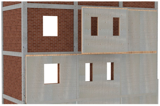
Figure 7.
RC–TPext assembly.
With regard to intervening on an intermediate storey of a building, the RC–TP execution procedure (Figure 8) is:
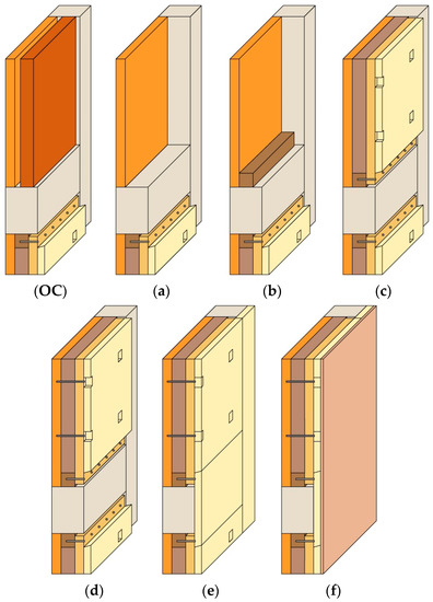
Figure 8.
RC–TP execution procedure: (OC) original configuration; (a–f) execution procedure.
- The demolition of the external solid brick wythe. Hammocks, to collect debris, must be placed on the scaffolding as a protection.
- The application of the timber subframe to the existing RC structure.
- The crane transportation of the prefabricated panel (provided with proper eyebolts) and the restraining thereof to the timber subframe.
- The connection of the remaining hollow-brick wythe with the CLT panel through resin-bonded bars with anchor sleeves.
- The finishing of the external insulating layer, covering of the holes and spaces with insulating material, and sealing of possible slits with foam.
- The application of an external plaster composed of a rendering coat, two layers of rustic plaster, and two layers of lime slurry paint.
With regard to intervening on an intermediate storey of a building, the RC–TPext execution procedure (Figure 9) consists of the following:
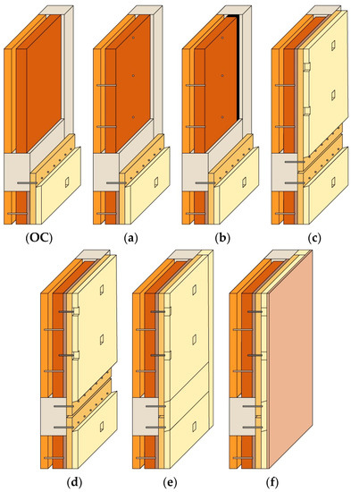
Figure 9.
RC–TPext execution procedure: (OC) Original Configuration; (a–f) execution procedure.
- (a)
- The connection of the masonry wythes through resin-bonded bars with anchor sleeves.
- (b)
- The disconnection of the external strong wythe from the columns (outlined in black). Hammocks to collect debris must be placed on the scaffolding as a protection (not necessary at the ground floor).
- (c)
- The crane transportation of the prefabricated panel (provided with proper eyebolts) and its restraining to the RC beams.
- (d)
- The connection of the CLT panel with the strong masonry wythe through dry steel anchors.
- (e)
- The finishing of the external insulating layer, covering of the holes and spaces with insulating material, and sealing of possible slits with foam.
- (f)
- The application of an external plaster composed of a rendering coat, two layers of rustic plaster, and two layers of lime slurry paint.
The proposed partial prefabrication represents a good middle ground between pure onsite execution and total prefabrication. Onsite execution relies on a classic work organization but requires a longer implementation time. Full prefabrication, instead, makes the use of scaffolding unnecessary, as scaffolding can be replaced by a mobile lift platform. Hence, the construction process is safer and faster but can hardly result in a perfectly uniform façade due to, for example, the panel-to-panel junctions. This aspect, however, is worthy of further study.
3. Seismic Analyses
The structural frame described in Section 2.1 was analysed considering horizontal actions in-plane and out-of-plane, and vertical actions. In particular, the focus of the present study regarded the in-plane behaviour of the bare frame, the masonry-infilled frame, and the retrofitted frame (with RC–TP and RC–TPext configurations). The study of the in-plane behaviour consisted of nonlinear static analyses that were performed via 2D finite element modelling, using the software SAP2000. However, a preliminary study of the capacity of the proposed system to resist out-of-plane and vertical actions is reported.
3.1. Vertical and Out-of-Plane Actions
Both out-of-plane and vertical actions were considered using simplified analytical approaches. Specifically, the reported static schemes were used to analyse RC–TP under vertical actions (a), RC–TP under horizontal out-of-plane actions (b,c), and RC–TPext under horizontal out-of-plane actions (d,e).
As reported in Section 2.2, because of the insertion of the CLT structural panels inside the concrete frame, only the RC–TP configuration can contribute to resist vertical actions in case of collapse or damage to the bearing elements.
The response of the RC–TP configuration under possible vertical action was investigated by assessing the minimum load that causes the buckling of the CLT panel. Until the gap between the panel and the beams is zeroed, any vertical force exchange between the panel and the beams is addressed by the screws that connect the CLT panel to the subframe. The resulting load-eccentricity was taken into account by introducing a bending moment at both extremities of the panel (static scheme in Figure 10a). The maximum bending moment was calculated based on the vertical action that the screws transfer when subjected to a deformation equal to the size of the gap (2 cm). When the gap size reaches zero, any additional axial load is transferred from the beam to the panel by direct contact. Therefore, any further increase in the axial load is assumed to be centred on the panel midline (i.e., without accounting for any eccentricity). The results obtained showed that the CLT panel could resist vertical loading compatible with that supported by the upper beams and by the columns at the base of a two-to-three storey building. As the collapse of a structural element could alter the load paths and cause significant relative deformations, the capacity of the proposed system to contribute to the resistance to vertical loads should be further investigated.
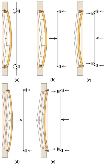
Figure 10.
Static schemes used to analyse: RC–TP under (a) vertical load, (b) horizontal external out-of-plane load, (c) horizontal internal out-of-plane load; RC–TPext under (d) horizontal external out-of-plane load, (e) horizontal internal out-of-plane load.
The out-of-plane responses of the RC–TP and RC–TPext systems was studied using the static schemes reported in Figure 10b–e. In particular, the masonry infills were considered only as seismic masses, neglecting, therefore, their contribution to the system’s capacity. By virtue of the connection between the masonry wythes and the CLT panel, and between the CLT panel and the RC frame (as reported in Section 2.2 and Section 2.3), the CLT panel provides an effective restraint to the overturning of the infills. Consequently, the CLT panel and connections (CLT-subframe and subframe-RC frame for RC–TP, and CLT-RC frame for RC–TPext) were checked against the design’s lateral action, which was calculated considering the seismic demand relative to a frame located on the fourth floor of a building. For all retrofit configurations, the CLT panel was verified for shear and bending, while the connections were verified for pull-out and shear. In the configurations analysed, the verifications performed on the CLT panel and the fasteners showed large safety margins, which confirm the ability of RC–TP and RC–TPext to prevent the overturning of the infills.
3.2. In-Plane Analyses—Numerical Models
The proposed intervention system aims at enhancing the in-plane seismic behaviour of the existing frames. As anticipated, the in-plane responses of bare, masonry infilled, and retrofitted frames were analysed via finite element modelling by performing nonlinear static in-plane analyses.
In all the configurations analysed, the concrete elements were modelled according to [21], as concerns material nonlinear behaviour and hinge characterisation. Specifically, deformation-controlled hinges were assigned at the extremities of columns and beams to simulate the post-elastic flexural behaviour, while force-controlled hinges were used to account for the shear failure. Furthermore, because the presence of strong beam–column joints was assumed, such joints were simulated as rigid in the numerical models. For the retrofitted frames, the nonlinear characterisation of the timber elements and the steel fasteners was based on the model presented in [21].
The double-wythe masonry infill was reproduced by modelling the two wythes separately, using the equivalent diagonal strut proposed by Liberatore et al. [36]. As this approach does not directly account for the shear stress that the masonry infill transfers to the columns, this additional action was evaluated a posteriori, based on the formulation proposed by [37]. In the event of shear collapse of a concrete element due to the additional stress transferred by the infill, a shear release was assigned to the collapsed element. Using the model thus modified, the analyses were then restarted from the step where the shear collapse had occurred.
As both retrofit configurations are supposed to preserve the internal wythe made of hollow-brick masonry, such wythes had to be modelled. The approach adopted was that proposed by [36], previously mentioned (see RC–TPext configuration in Figure 11a). As was done for the masonry-infill configuration, the additional shear in the columns due to the infill-frame interaction was considered a posteriori. Acknowledging that the chances of shear collapse of the retrofitted frames due to the infill-frame interaction would be higher if the internal wythe was made of stiffer and stronger masonry, the responses of the retrofit systems (RC–TP and RC–TPext) were investigated, also considering such scenario. Consequently, two additional retrofitted models were analysed, simulating the presence of strong internal masonry wythes (named “AW”), whose characteristics are reported in Table 4.
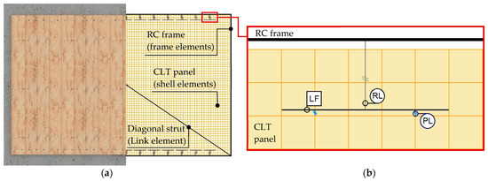
Figure 11.
RC–TPext finite element model: (a) complete intervention system; (b) interaction system.
Table 4.
Material properties of the alternative internal wythe “AW”.
In the RC–TP configuration, the external solid-masonry wythe is completely removed from the frame. Therefore, the external wythe was not implemented in the numerical model of the frame retrofitted with the RC–TP. In the RC–TPext configuration, instead, the external wythe is isolated from the RC columns by cutting the lateral edges of the wythe creating a 3-cm wide gap at the infill-to-column interfaces. Conversely, the bonding between the upper edge of the infill and the concrete beam is not affected by the retrofit intervention. Consequently, even though the external wythe is not removed, it does not transfer additional shear stress to the columns. Therefore, the external solid masonry wythe was simulated in the numeric model by an equivalent diagonal strut, but no additional column shear needed to be computed a posteriori.
Regarding the system that governs the interaction between concrete and timber elements, in the RC–TP configuration it was modelled according to [21]. For the RC–TPext configuration, instead, a specific interaction system was developed for this study. As visible in Figure 11b, one-dimensional (1D) frame elements are placed at the midline of the concrete beams and columns to simulate the RC frame. The frame elements are connected to the bidimensional (2D) shell elements, simulating the CLT panel through a system composed of 1D frame and link elements. Specifically, the LF (line of fasteners frame) marks the line where the metal fasteners are inserted. The LF is rigid and works as a support for the panel-to-frame link (PL) elements, which reproduce the behaviour of each fastener in the timber-to-concrete. The LF is connected to the 1D elements of the RC frame through a rigid link (RL) that makes the LF move and rotate solidly with the RC frame. The PLs are nonlinear links whose behaviour was defined consistently with reference to [21].
3.3. In-Plane Responses
Figure 12 reports the results obtained considering the bare frame “BR”, the masonry infilled frame “MI”, the two retrofit configurations “RC–TP” and “RC–TPext”, and the two retrofit configurations with a stronger internal masonry wythe (see details in Table 4) “RC–TP_AW” and “RC–TPext_AW”.
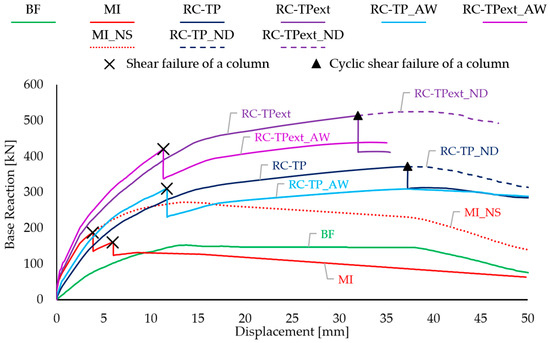
Figure 12.
Isolated frame backbone curves: bare frame (BF); masonry-infilled frame (MI); masonry-infilled frame with additional shear not accounted (MI_NS); retrofitted frame with the most invasive (RC–TP) and, the least invasive configuration, (RC–TPext); retrofitted frame with shear degradation not accounted in the most invasive (RC–TP_ND) or the least invasive configurations (RC–TPext_ND); a retrofitted frame, assuming a stronger alternative internal masonry wythe in the most invasive (RC–TP_AW) and least invasive configurations (RC–TPext_AW).
As expected, the original masonry-infilled configuration, MI, showed an initial stiffness higher than that of the BF, RC–TP and RC–TP_AW configurations, and similar to that of the RC–TPext and RC–TPext_AW. However, at a displacement level close to 3 mm, MI exhibited a sudden two-step loss of lateral capacity, due to the shear failure of the columns (indicated with a black “” in Figure 12), as a consequence of the additional shear stresses transferred by the masonry infill. Such premature capacity losses were not observed in the retrofitted configuration due to the absence of any additional shear actions from the external solid masonry wythe. The collapse observed in MI attest to the importance of considering the additional shear due to the interaction between RC frame and masonry infill. Specifically, the red dotted curve reproduces the behaviour that the masonry-infilled frame would have if the additional shear stress were neglected (MI_NS in Figure 12).
The RC–TP and RC–TPext retrofitted frames showed ductile behaviour governed by the bending failure of the concrete elements and by the progressive yielding of the screw fasteners. However, at displacement levels ranging between 32 mm (RC–TPext) and 37 mm (RC–TP), both retrofit configurations experienced shear failure of one of their columns. It is worth highlighting that in the cases of the RC–TP and RC–TPext configurations, the column shear strength was negatively affected by the large ductile flexural deformation of the columns. The phenomenon has been well described by Priestley et al. [38]: “as plastic-hinge rotations increase, the widening of flexure-shear cracks reduces the capacity for shear transfer by aggregate interlock, and the shear strength reduces”. The formulation proposed by Biskinis et al. [39] that accounts for degradation due to inelastic cyclic displacements was considered. In Figure 12, the collapse due to the shear strength degradation (cyclic shear) is indicated with a black triangle “▲”. If this degradation was not accounted for, the two systems (RC–TP and RC–TPext) would respond as represented by the dashed curves (RC–TP_ND and RC–TPext_ND, respectively).
As already mentioned, the RC -TP_AW and RC–TPext_AW configurations simulate the presence of a stronger internal masonry wythe. As can be seen in Figure 12, the additional stress transferred by this wythe induces column shear failure at displacements significantly lower than those reached in the RC–TP and RC–TPext configurations. This aspect confirms the importance of evaluating the stiffness and strength of the masonry infill with due care. When the infill-frame interaction is expected to cause damage to the concrete frame, either the removal of the infill or the introduction of lateral cuts to isolate the infill wythes from the frame columns, should be evaluated.
4. Energy Analyses
The energy performance of buildings depends on the thermal properties of their envelope, which separates the indoor and outdoor environment and interacts with climatic factors. In the following energy analyses, reference was made to the opaque components of the envelope (i.e., perimeter walls), which are the elements affected by the proposed retrofit solution and that play a predominant role in determining the envelope performance. The study is based on the climatic conditions of the temperate zones of countries in southern Europe.
To provide masonry walls with adequate thermal resistance and thus reach the minimum resistance prescribed by most design codes, the addition of insulating materials is required. The insulating layer should cover the entire façade, minimising material discontinuities (i.e., thermal bridges) through which heat could exit. However, thermal insulation increases the chance of surface condensation, especially during winter months, when the external humidity levels are higher [40]. The presence of moisture condensation on the exterior walls leads to the growth of undesirable mildew, which affects the durability of materials [41]. Interstitial condensation must also be verified to prevent material degradation [41] (e.g., mechanical properties of CLT and thermal properties of the insulating layers). Finally, the summer behaviour of the envelope, which affects indoor comfort, should be investigated considering multiple factors, such as periodic transmittance or areal heat capacity.
With reference to the isolated RC frame previously described, both the RC–TP and RC–TPext configurations were analysed and compared with the existing masonry infill. The outer temperatures and humidity levels were related to a city in the north of Italy (Turin). The characteristics of the materials and the thickness of the layers are reported in Table 5, Table 6 and Table 7.
Table 5.
Existing masonry infill.
Table 6.
RC–TP configuration.
Table 7.
RC–TPext configuration.
4.1. Thermo-Hygrometric Performance in Winter Conditions
In Table 8, a comparison between the thermal transmittance of the existing conditions and the retrofit configurations is reported. Transmittance calculation is based on UNI EN ISO 6946:2018 [44].
Table 8.
Thermal transmittance.
The hygrothermal behaviour of the walls was investigated in the most critical months for the risk of mould growth and the risk of surface condensation, following the prescriptions of UNI EN ISO 13788:2013 [45]. Table 9 and Table 10 refer to mould growth risk and surface condensation risk, while, in Figure 13, Figure 14 and Figure 15, the interstitial condensation risk was examined.
Table 9.
Mould growth risk in the most critical month (November).
Table 10.
Surface condensation risk in the most critical month (January).
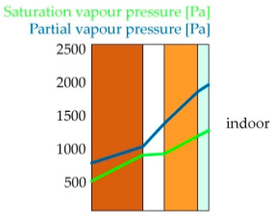
Figure 13.
Diagram for saturation and partial vapour pressure in the existing masonry infill (month: January). No interstitial condensation phenomena occur.
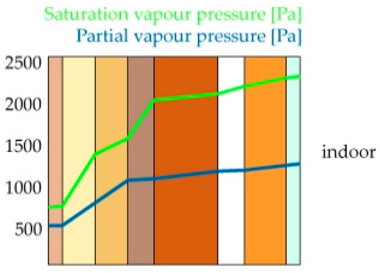
Figure 14.
Diagram for saturation and partial vapour pressure in the RC–TPext configuration (month: January). No interstitial condensation phenomena occur.
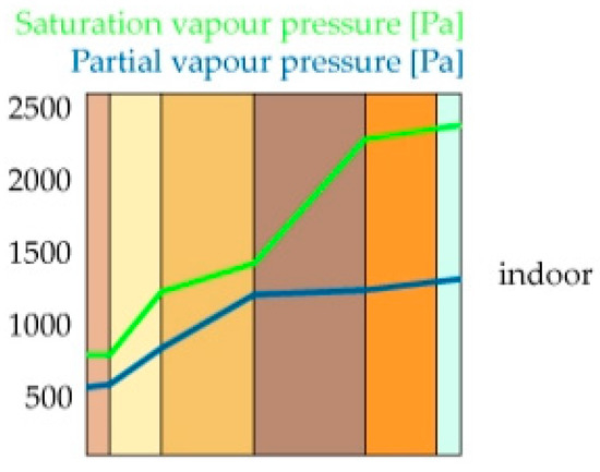
Figure 15.
Diagram for saturation and partial vapour pressure in the RC–TP configuration (month: January). No interstitial condensation phenomena occur.
4.2. Thermal Performance in Summer Conditions
As the summer behaviour of walls is subject to important variations throughout the day, it requires dynamic thermal simulations. As reported in Table 11, Table 12 and Table 13, some relevant factors to determine this behaviour were calculated, according to UNI EN ISO 13786:2018 [46,47].
Table 11.
Parameters that influence the summer performance of existing walls.
Table 12.
Parameters that influence the summer performance of the RC–TP configuration.
Table 13.
Parameters that influence the summer performance of the RC–TPext configuration.
Both retrofit configurations provide an overall improvement of envelope performance, especially in winter conditions. However, when facing a real case study, it is also important to analyse thermal bridges to investigate the possible formation of mildew during the most critical month.
5. Case Study
The proposed retrofit solution was applied to an existing RC framed building located in the north of Italy that was built in 1955. It has five floors and a basement, which are connected through two staircases. Each staircase is delimited by two RC walls parallel to the shortest side of the building. The structural frames are provided with double-wythe masonry infills, with an external strong wythe and an internal weak wythe, separated by an air gap (Figure 16).
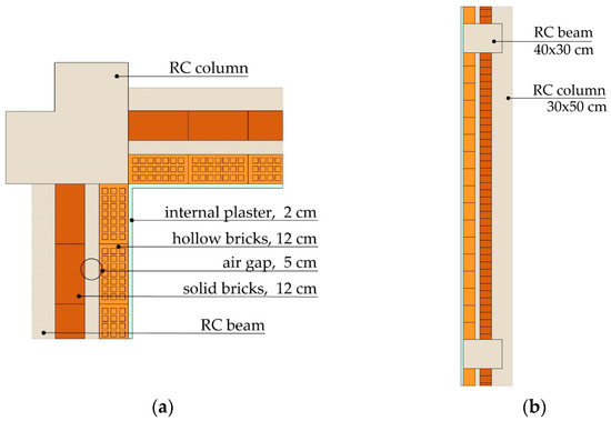
Figure 16.
Original structural frame: (a) plan; (b) section.
The two proposed intervention configurations were applied to the building, defining two different levels of retrofit. The RC–TPext strategy corresponds to the least invasive level, named L-I (least-invasive), which affects only the envelope, while the RC–TP solution is part of a larger renovation, named M-I (most-invasive), which includes the replacement of the building services and the use of renewable energy. The L-I intervention can be carried out by intervening only from the outside of the building, to minimize the disturbance to the occupants. The M-I intervention, on the other hand, aims to maximize the building efficiency.
5.1. Intervention Application and Alternative Solutions
As the structural frames of the case-study building have columns that are larger than the beams, the structural details of both RC–TP and RC–TPext were adapted to optimise the effectiveness of the interventions for this geometric configuration (Figure 17 and Figure 18). The RC–TP configuration reported in Figure 17 shows a generic implementation where the timber subframe is arranged on both columns and beams according to the implementation rules presented in [23].
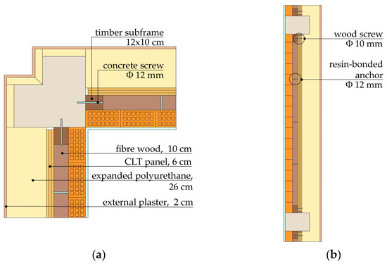
Figure 17.
RC–TP configuration, applied to the case-study structural frame: (a) plan; (b) section.
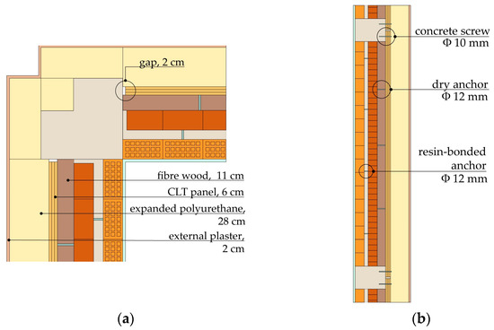
Figure 18.
RC–TPext configuration, applied to the case-study structural frame: (a) plan; (b) section.
For the M-I and L-I interventions, the RC–TP (M-I) and the RC–TPext (L-I) retrofits were applied extensively, from the bottom of the façades to the top. These solutions were implemented in every frame vulnerable to the design seismic action, even though, due to geometric constraints, not all the frame bays saw the application of the timber panel (e.g., in some bays of the outermost frames in the northwest façade, the infill was not aligned with the frame plane but was moved inward, see Figure 19a). The CLT panel retrofit was also not applied to a few frames in which the infill–frame interaction was expected not to be detrimental to the frame’s resistance. In particular, this concerns the infilled frames that delimit the stairwells in the southeast façade. In these frames, the opening size is greater than 50% of the total infill surface, making the risk of a dangerous interaction with the RC elements negligible [48].
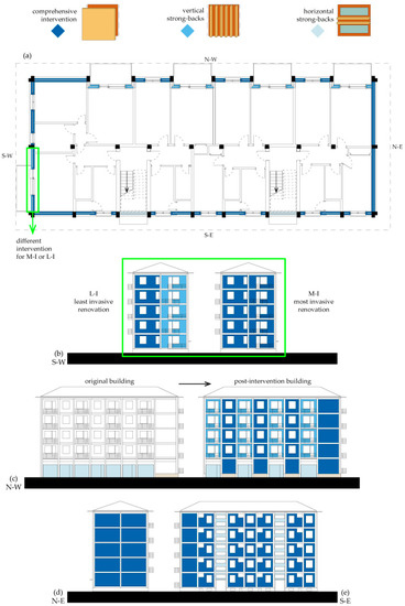
Figure 19.
Case study—intervention strategies: (a) plan; (b) S-W frontage; (c) N-W frontage; (d) N-E frontage; (e) S-E frontage.
To avoid the overturning of the infills of the frame bays, where the CLT panel could not be applied, the use of timber strong-backs [49] was proposed. Based on the geometry of the problem at hand, strong-backs of size 4 cm × 11 cm, fixed to the existing masonry infills and spaced at approximately 60 cm apart, were adopted. For the frame bays with a balcony, vertical strong-backs were used, while for the stairwell infills, horizontal strong-backs were preferred, due to the shape of the openings.
In the RC frame bays with balconies facing the southwestern side, it was not possible to apply the RC–TPext configuration, due to the presence of the balcony slabs preventing the panels from being fixed to the beams. Consequently, as Figure 19b shows, the frame bays with a balcony were retrofitted with the RC–TP solution in the M-I intervention, while in the L-I intervention, vertical strong-backs were applied after the lateral disconnection of the external wythe from the columns.
In the original building, the absence of infills on the ground floor of the N-W frontage caused an irregular distribution of stiffness in plane and elevation that could lead to torsional effects and/or to soft-storey mechanisms. In addition, due to the absence of the base curb along this frontage, the resulting slender columns further facilitated these phenomena. Consequently, a rearrangement of non-structural elements on the N-W frontage was designed (Figure 19c). It was considered to maintain the original openings under the balcony frames, and to implement the intervention systems in the other frames. At the ground level, for frames that are not located under balconies, a concrete curb similar to the one present on the other facades was designed. In this way, the CLT panels could be restrained to the new concrete curb and then be applied continuously from the bottom to the top of the building. The introduction of the curb avoids the presence of slender columns and lets the timber elements to be separated from the ground, avoiding the contact with water.
Finally, Figure 19d,e show that on the northeast and southeast facades the comprehensive intervention could be applied to all the frames, with the only exception being those delimiting the two stairwells, where horizontal strong-backs were used.
5.2. Energy Analysis of a Retrofitted Apartment
For the energetic analyses, reference was made to an apartment located on an intermediate floor, as highlighted in Figure 20.
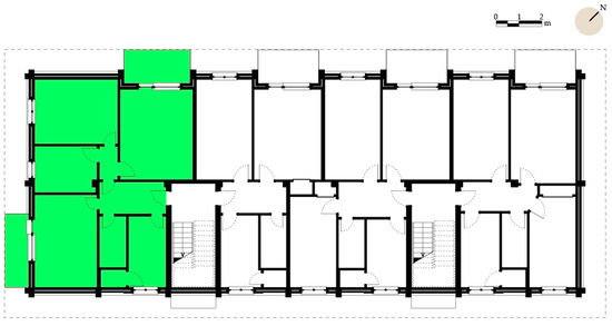
Figure 20.
Existing building plan of an intermediate floor. The analysed apartment is highlighted in green.
The apartment was selected because it had three side-facing walls and include both types of balcony frame-bay (Figure 20). It was assumed that the apartment has independent services. After investigating the performance of a single retrofitted frame, analyses on the comprehensive behaviour of the renovated apartment were performed for both retrofit configurations. Specifically, the analyses refer to annual energy consumption and to thermal bridges. The results were compared with the results obtained for the as-built conditions.
The least invasive intervention, L-I, saw the use of the RC–TPext configuration and the insulation of the not-habitable attic. Existing doors and windows were left in place, assuming that their thermo-hygrometric performance was sufficient to ensure the absence of indoor surface condensation. This proposed renovation affected only the building’s envelope and could be carried out entirely from outside the dwellings.
The most invasive intervention, M-I, saw the use of the RC–TP solution, the insulation of the attic, stairwells, and basement and the replacement of doors and windows. Furthermore, a new heating and cooling system was provided that an collaborates with solar and photovoltaic panels. In this case, such renovation requires a longer and more expensive implementation, but ensures optimal energy performance.
In Table 14 and Figure 21 the global energy consumption and the energy needed for apartment heating in one year are reported.
Table 14.
Annual energy consumption (total and for heating) for the analysed apartment.
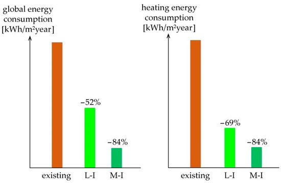
Figure 21.
Energy consumption reduction (global and for heating).
The constructive details for both intervention configurations were designed with attention paid to avoiding the possibility of superficial mould growth. The main thermal bridges were analysed, verifying that the calculated temperature coefficient (fRsi) was higher than the minimum temperature coefficient for mould growth risk (fRsi min) according to UNI EN ISO 13788 [45]. In Figure 22, Figure 23 and Figure 24, the analysed details are reported.
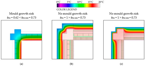
Figure 22.
Angular thermal bridge. Comparison between: (a) existing conditions; (b) RC–TP; (c) RC–TPext.
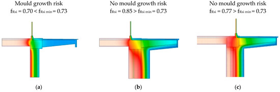
Figure 23.
Balcony slab thermal bridge. Comparison between: (a) existing conditions; (b) RC–TP; (c) RC–TPext.
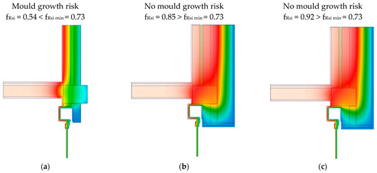
Figure 24.
Upper window thermal bridge. Comparison between: (a) existing conditions; (b) RC–TP; (c) RC–TPext.
6. Conclusions
In this research, an integrated intervention approach was presented that aims to improve both the seismic and thermal behaviours of existing RC frames. Specifically, two intervention strategies characterized by different levels of invasiveness were developed for RC frames with double-wythe masonry infills. The most-invasive configuration (RC–TP) sees the removal of the external wythes and the insertion of CLT panels inside the concrete frame. In the least-invasive configuration (RC–TPext), instead, the CLT panels are applied from the outside without removing the existing infill.
The first step of the research involved seismic and energetic analyses of an isolated one-storey, one-bay frame, representative of the built heritage of many countries. Using both the retrofit configurations, the RC frame showed significant improvements in in-plane response in terms of displacement and load-bearing capacity. Furthermore, the proposed intervention resulted in a capacity for facing horizontal out-of-plane actions (both RC–TP and RC–TPext) and to resist huge increments in vertical actions due to collapses or damage to the structural elements (RC–TP).
The durability and energetic aspects (e.g., mould growth, surface and interstitial condensation, summer and winter performances) were studied in parallel with the implementation details. A partial prefabrication of the system was also proposed.
In the final phase of the research, a case-study building was subjected to two alternative retrofit strategies. The least invasive strategy is based on the RC–TPext configuration and affects only the envelope, allowing all onsite operations to be performed from outside the building. The most invasive configuration, instead, relies on the RC–TP configuration and includes the replacement of the building services and the use of renewable energy. In both strategies, timber strong-backs were used to prevent the out-of-plane failure of those frames for which it was not possible or convenient to apply the CLT panels. Considering an apartment located on an intermediate floor, pre- and post-intervention energetic analyses were performed.
The results obtained showed that the proposed intervention can significantly improve both the seismic and energetic behaviours of existing RC buildings. In addition, the possibility of preassembling the intervention system can guarantee fast execution and little disturbance to the occupants.
Author Contributions
Conceptualization, F.S., I.P., I.G., S.Z., R.A. and M.P.; funding acquisition, I.G., R.A. and M.P.; investigation, F.S. and I.P.; methodology, F.S., I.P., I.G. and S.Z.; supervision, I.G., R.A. and M.P.; writing—original draft preparation, F.S. and I.P.; writing—review and editing, I.G., S.Z., R.A. and M.P. All authors have read and agreed to the published version of the manuscript.
Funding
This research received no external funding.
Institutional Review Board Statement
Not applicable.
Informed Consent Statement
Not applicable.
Data Availability Statement
Not applicable.
Acknowledgments
The research work was carried out within the framework of the 2019–2021 ReLUIS-DPC network (Italian University Network of Seismic Engineering Laboratories and Italian Civil Protection Agency). This work was supported by the Italian Ministry of Education, University and Research (MIUR) in the frame of the ‘Department of Excellence’ (grant L 232/2016).
Conflicts of Interest
The authors declare no conflict of interest. The funders had no role in the design of the study; in the collection, analyses, or interpretation of data; in the writing of the manuscript, or in the decision to publish the results.
References
- Kasanko, M.; Barredo, J.I.; Lavalle, C.; McCormick, N.; Demicheli, L.; Sagris, V.; Brezger, A. Are European cities becoming dispersed? A comparative analysis of 15 European urban areas. Landsc. Urban Plan. 2006, 77, 111–130. [Google Scholar] [CrossRef]
- European Parliament and Council. Directive (EU) 2018/844 Amending Directive 2010/31/EU on the Energy Performance of Buildings and Directive 2012/27/EU on Energy Efficiency. Available online: https://eur-lex.europa.eu/legal-content/EN/TXT/HTML/?uri=CELEX:32018L0844&from=IT (accessed on 28 June 2021).
- European Commission, Department: Energy. In Focus: Energy Efficiency in Buildings. Brussels, 17 February 2020. Available online: https://ec.europa.eu/info/news/focus-energy-efficiency-buildings-2020-feb-17_en (accessed on 25 June 2021).
- Afshari, A.; Anderson, H.R.; Cohen, A.; Oliveira Fernandes, E.; Douwes, J.; Górny, R.; Hirvonen, M.R.; Jaakkola, J.; Kirchner, S.; Kurnitski, J.; et al. WHO Guidelines for Indoor Air Quality: Dampness and Mould; World Health Organization: Copenhagen, Denmark, 2009. [Google Scholar]
- Pombo, O.; Rivela, B.; Neila, J. The challenge of sustainable building renovation: Assessment of current criteria and future outlook. J. Clean. Prod. 2016, 123, 88–100. [Google Scholar] [CrossRef]
- Kadysiewski, S.; Mosalam, K.M. Modeling of Unreinforced Masonry Infill Walls, Considering. In Plane and Out-of-Plane Interaction; Pacific Earthquake Engineering Research Center, University of California: Berkeley, CA, USA, 2009. [Google Scholar]
- D’Aragona, M.G.; Polese, M.; Di Ludovico, M.; Prota, A. Seismic vulnerability for RC infilled frames: Simplified evaluation for as-built and retrofitted building typologies. Buildings 2018, 8, 137. [Google Scholar] [CrossRef] [Green Version]
- Mosalam, K.M.; Günay, S. Progressive Collapse Analysis of Reinforced Concrete Frames with Unreinforced Masonry Infill Walls Considering In-Plane/Out-of-Plane Interaction. Earthq. Spectra 2015, 31, 921–943. [Google Scholar] [CrossRef]
- Tarque, N.; Candido, L.; Camata, G.; Spacone, E. Masonry infilled frame structures: State-of-the-art review of numerical modelling. Earthq. Struct. 2015, 8, 733–759. [Google Scholar]
- Al Louzi, R.A.K. Seismic In-Plane Response of Reinforced Concrete Frames with Masonry Infill Walls. Ph.D. Thesis, Purdue University, Lafayette, IN, USA, 2015. [Google Scholar]
- Sustersic, I.; Dujic, B. Seismic strengthening of existing buildings with cross laminated timber panels. In Proceedings of the World Conference on Timber Engineering, Auckland, New Zealand, 16–19 July 2012. [Google Scholar]
- Suga, J.; Ono, M.; Aoki, K.; Fukuhara, T.; Kurihara, T.; Maeda, T. Timber Shear Walls for Seismic Retrofit of Reinforced Concrete Buildings. In Proceedings of the World Conference on Timber Engineering, Seoul, Korea, 20–23 August 2018. [Google Scholar]
- Gioiella, L.; Balducci, A.; Carbonari, S.; Gara, F.; Dezi, L. An innovative seismic protection system for existing buildings: External dissipative towers. In Proceedings of the 16th World Conference on Earthquake Engineering (16WCEE), Santiago, Chile, 9–13 January 2017. [Google Scholar]
- Abd Alla, S.; Bianco, V.; Tagliafico, L.A.; Scarpa, F. Life-cycle approach to the estimation of energy efficiency measures in the buildings sector. Appl. Energy 2020, 264, 114745. [Google Scholar] [CrossRef]
- Parasonis, J.; Keizikas, A.; Endriukaitytė, A.; Kalibatienė, D. Architectural solutions to increase the energy efficiency of buildings. J. Civ. Eng. Manag. 2012, 18, 71–80. [Google Scholar] [CrossRef]
- Ampatzidis, P.; Serasidou, A.; Tsiaousi, A.; Martinopoulos, G. High energy efficiency renovation options for a typical apartment. The case study of the SPITI project. IOP Conf. Ser. Earth Environ. Sci. 2020, 410, 012060. [Google Scholar] [CrossRef]
- Labo’, S.; Passoni, C.; Belleri, A.; Marini, A.; Riva, P. Esoscheletri tipo diagrid per la riqualificazione degli edifici esistenti in ottica ciclo vita. Costr. Met. 2019, 5, 24–35. [Google Scholar]
- Marini, A.; Passoni, C.; Belleri, A.; Feroldi, F.; Preti, M.; Metelli, G.; Riva, P.; Giuriani, E.; Plizzari, G. Combining seismic retrofit with energy refurbishment for the sustainable renovation of RC buildings: A proof of concept. Eur. J. Environ. Civ. Eng. 2017, 1–21. [Google Scholar] [CrossRef]
- Margani, G.; Evola, G.; Tardo, C.; Marino, E.M. Energy, Seismic, and Architectural Renovation of RC Framed Buildings with Prefabricated Timber Panels. Sustainability 2020, 12, 4845. [Google Scholar] [CrossRef]
- Artino, A.; Evola, G.; Margani, G.; Marino, E.M. Seismic and Energy Retrofit of Apartment Buildings through Autoclaved Aerated Concrete (AAC) Blocks Infill Walls. Sustainability 2019, 11, 3939. [Google Scholar] [CrossRef] [Green Version]
- Smiroldo, F.; Viel, D.; Giongo, I.; Piazza, M. A Numerical study on a timber-based seismic retrofit intervention for masonry infilled concrete frames. COMPDYN 2021. In Proceedings of the 8th ECCOMAS Thematic Conference on Computational Methods in Structural Dynamics and Earthquake Engineering, Athens, Greece, 27–30 June 2021. [Google Scholar]
- Smiroldo, F.; Giongo, I.; Piazza, M. Use of timber panels to reduce the seismic vulnerability of concrete frame structures. Eng. Struct. 2021, 244, 112797. [Google Scholar] [CrossRef]
- Smiroldo, F.; Giongo, I.; Piazza, M. Seismic retrofit of masonry infilled frames by using timber panels. In Proceedings of the 17th World Conference on Earthquake Engineering (17WCEE), Sendai, Japan, 13–18 September 2020. [Google Scholar]
- Masi, A.; Manfredi, V.; Ventura, G. Progettazione integrata di interventi per il miglioramento delle prestazioni sismiche e termiche di edifici esistenti in c.a. In Proceedings of the XVI Convegno ANIDIS, L’Aquila, Italy, 13–17 September 2015. [Google Scholar]
- Furtado, A.; Rodrigues, H.; Arêde, A.; Varum, H. Double-wythe infill masonry walls cyclic in-plane behaviour: Experimental and numerical investigation. Open Constr. Build. Technol. J. 2018, 12, 35–48. [Google Scholar] [CrossRef] [Green Version]
- Furtado, A.; Costa, C.; Rodrigues, H.; Arêde, A. Characterization of structural characteristics of Portuguese RC buildings with masonry infill walls stock. In Proceedings of the 9th International Masonry Conference, Guimarães, Portugal, 7–9 July 2014. [Google Scholar]
- Bala, E.; Crowleyb, H.; Pinhoc, R.; Gülayd, F.G. Detailed assessment of structural characteristics of Turkish RC building stock for loss assessment models. Soil Dyn. Earthq. Eng. 2008, 28, 914–932. [Google Scholar] [CrossRef]
- Manfredi, G.; Masi, A.; Pinho, R.; Verderame, G.; Vona, M. Valutazione Degli Edifici Esistenti in Cemento Armato; IUSS Press: Pavia, Italy, 2007. [Google Scholar]
- Cristofaro, M.T.; D’Ambrisi, A.; De Stefano, M.; Pucinotti, R.; Tanganelli, M. Studio sulla dispersione dei valori di resistenza a compressione del calcestruzzo di edifici esistenti. Il G. Delle Prove Non Distruttive Monit. Diagn. 2012, 2, 32–39. [Google Scholar]
- Cristofaro, M.T.; D’Ambrisi, A.; De Stefano, M.; Pucinotti, R.; Tanganelli, M. Mechanical Characterization of Concrete from Existing Buildings with SonReb Method. In Proceedings of the 15th World Conference on Earthquake Engineering (15WCEE), Lisboa, Portugal, 24–28 September 2012. [Google Scholar]
- Verderame, G.M.; Ricci, P.; Esposito, M.; Sansiviero, F.C. Le Caratteristiche Meccaniche degli Acciai Impiegati nelle Strutture in C.A. Realizzate dal 1950 al 1980. In Proceedings of the Atti Convegno AICAP, Paper 54, Padua, Italy, 19–21 May 2011. [Google Scholar]
- Ministero delle Infrastrutture e dei Trasporti. CNTC19—Circolare Applicativa Delle Norme Tecniche Delle Costruzioni di Cui al D.M. 17 January 2018 (NTC 2018); Gazzetta Ufficiale, n. 35; Ministero delle Infrastrutture e dei Trasporti: Rome, Italy, 11 February 2019. (In Italian)
- EN 14080:2013. Timber Structures—Glued Laminated Timber and Glued Solid Timber—Requirements; European Committee for Standardization: Brussels, Belgium, 2013. [Google Scholar]
- EN 338:2016. Structural Timber—Strength Classes; BSI Standards Publication: London, UK, 2016. [Google Scholar]
- Ott, S.; Tietze, A.; Winter, S. Introduction of a semi-probabilistic moisture safety model for tall timber- based building shell—A risk based durability approach. In Proceedings of the IALCCE 2016 (The Fifth International Symposium on Life-Cycle Civil Engineering), Delft, The Netherlands, 16–19 October 2016. [Google Scholar]
- Liberatore, L.; Noto, F.; Mollaioli, F.; Franchin, P. In-plane response of masonry infill walls: Comprehensive experimentally-based equivalent strut model for deterministic and probabilistic analysis. Eng. Struct. 2018, 167, 533–548. [Google Scholar] [CrossRef]
- Di Trapani, F.; Malavisi, M. Seismic fragility assessment of infilled frames subject to mainshock/aftershock sequences using a double incremental dynamic analysis approach. Bull. Earthq. Eng. 2019, 17, 211–235. [Google Scholar] [CrossRef]
- Priestley, M.J.N.; Verma, R.; Xiao, Y. Seismic shear strength of reinforced concrete columns. J. Struct. Eng. 1994, 120, 2310–2329. [Google Scholar] [CrossRef]
- Biskinis, D.E.; Roupakias, G.K.; Fardis, M.N. Degradation of shear strength of reinforced concrete members with inelastic cyclic displacement. ACI Struct. J. 2004, 101, 773–783. [Google Scholar]
- Aelenei, D.; Henriques, F.M.A. Analysis of the condensation risk on exterior surface of building envelopes. Energy Build. 2008, 40, 1866–1871. [Google Scholar] [CrossRef]
- Sadineni, S.B.; Madala, S.; Boehm, R.F. Passive building energy savings: A review of building envelope components. Renew. Sustain. Energy Rev. 2011, 15, 3617–3631. [Google Scholar] [CrossRef]
- UNI/TR 11552:2014. Opaque Envelope Components of Buildings—Thermo-Physical Parameters; Ente Italiano di Normazione (UNI): Milano, Italy, 2014. [Google Scholar]
- UNI EN ISO 6946:2018. Building Components and Building Elements—Thermal Resistance and Thermal Transmittance—Calculation Methods; Ente Italiano di Normazione (UNI): Milano, Italy, 2018. [Google Scholar]
- UNI 10351:2015. Building Materials and Products—Hygrothermal Proprieties—Procedure for Determining the Design Values; Ente Italiano di Normazione (UNI): Milano, Italy, 2015. [Google Scholar]
- UNI EN ISO 13788:2013. Hygrothermal Performance of Building Components and Building Elements—Internal Surface Temperature to Avoid Critical Surface Humidity and Interstitial Condensation—Calculation Methods; Ente Italiano di Normazione (UNI): Milano, Italy, 2013. [Google Scholar]
- UNI EN ISO 13786:2018. Thermal Performance of Building Components—Dynamic Thermal Characteristics—Calculation Methods; Ente Italiano di Normazione (UNI): Milano, Italy, 2018. [Google Scholar]
- Rossi, M.; Rocco, V.M. External walls design: The role of periodic thermal transmittance and internal areal heat capacity. Energy Build. 2014, 68, 732–740. [Google Scholar] [CrossRef]
- Tabeshpour, M.R.; Noorifard, A. A new procedure to determine equivalent strut of infill walls with openings for engineering applications. Struct. Build. 2020, 173, 585–601. [Google Scholar] [CrossRef]
- Cassol, D.; Giongo, I.; Ingham, J.; Dizhur, D. Seismic out-of-plane retrofit of URM walls using timber strong-backs. Constr. Build. Mater. 2020, 269, 121237. [Google Scholar] [CrossRef]
Publisher’s Note: MDPI stays neutral with regard to jurisdictional claims in published maps and institutional affiliations. |
© 2021 by the authors. Licensee MDPI, Basel, Switzerland. This article is an open access article distributed under the terms and conditions of the Creative Commons Attribution (CC BY) license (https://creativecommons.org/licenses/by/4.0/).