Bacterial Flagellum versus Carbon Nanotube: A Review Article on the Potential of Bacterial Flagellum as a Sustainable and Green Substance for the Synthesis of Nanotubes


Abstract
1. Introduction
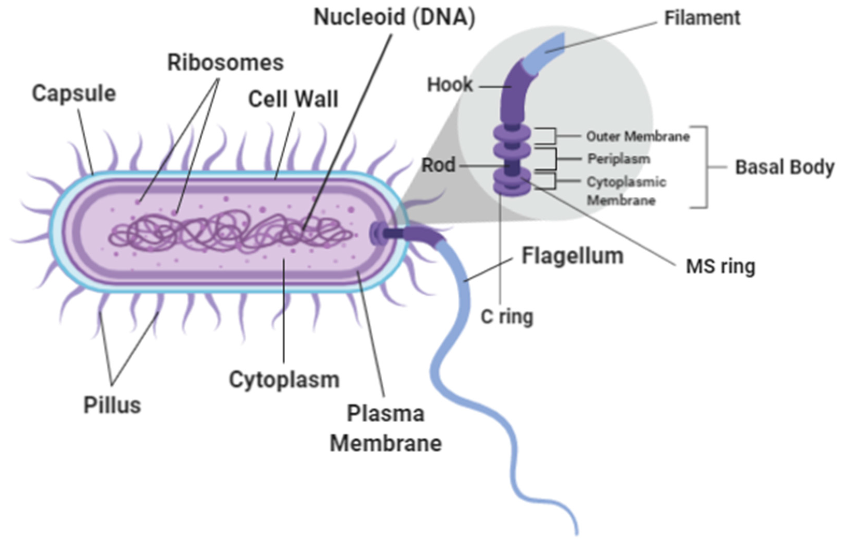
2. The Bacterial Flagellum
2.1. Flagellar Structure
2.2. Flagellar Motor
2.3. Types of Flagella
3. Applications of Bacterial Flagella
3.1. Bacterial Flagella as Biotemplated Nanomaterials for Electronics
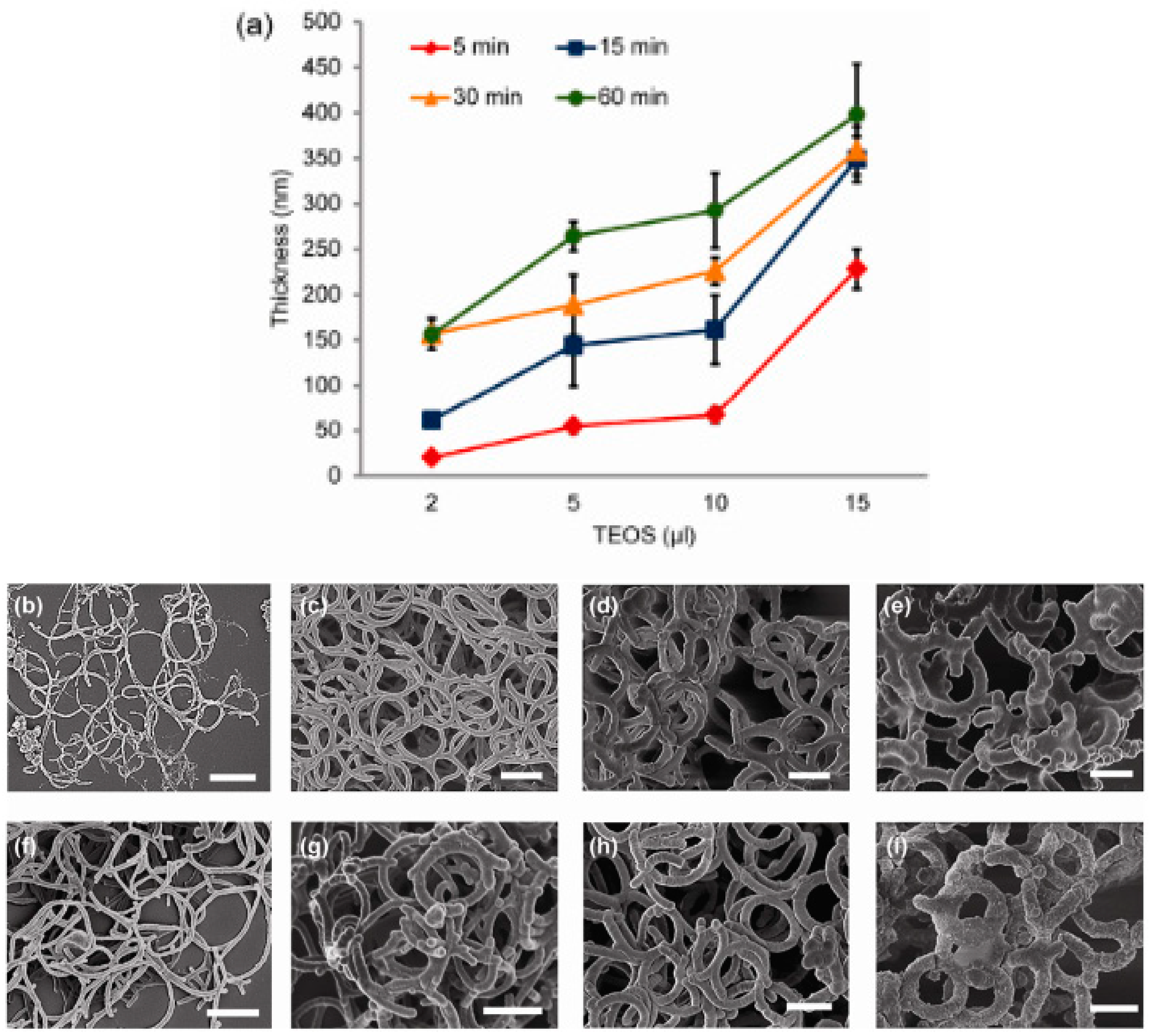
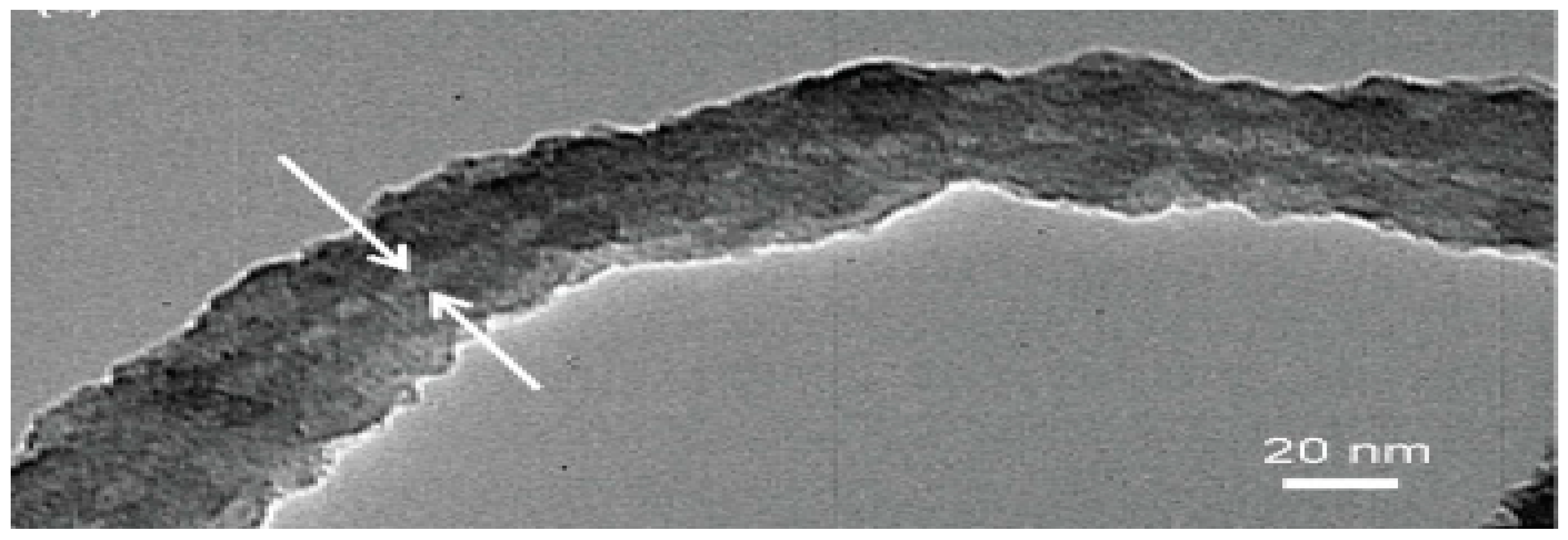
3.2. Bacterial Flagella as Templates for Silica Fibers
3.3. Biotemplated Bacterial Flagellar as Nanoswimmers
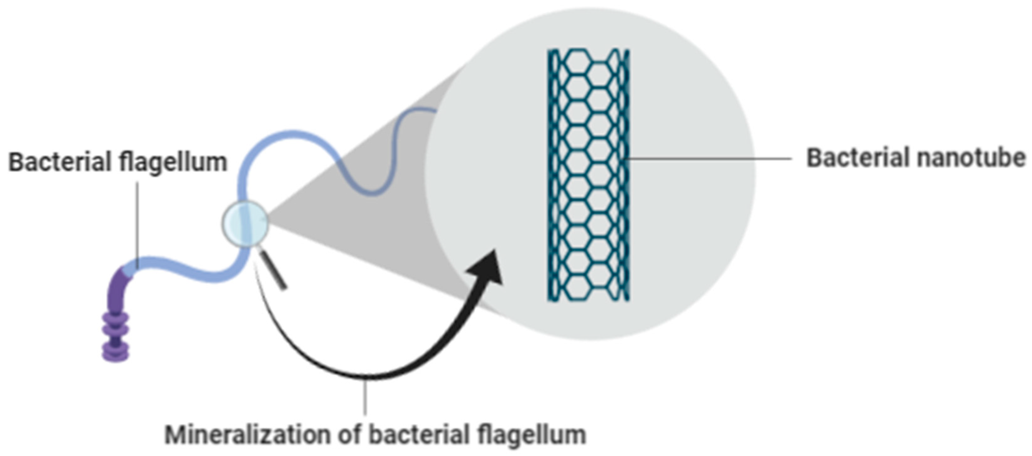
3.4. Mineralization of Bacterial Flagella for Nanotube Formation
4. Synthesis of Nanotubes from Bacterial Flagella
5. Carbon Nanotubes (CNTs)
Types of Carbon Nanotubes (CNTs)
6. Applications of Carbon Nanotubes (CNTs)
6.1. Electronic Devices Using CNTs
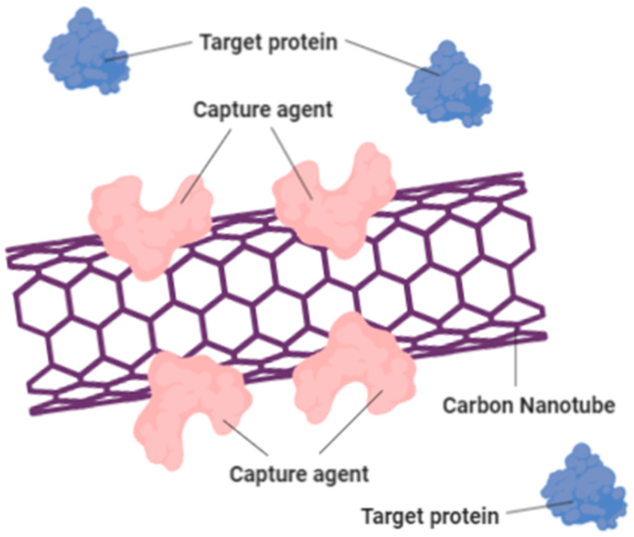
6.2. Sensors Using CNTs
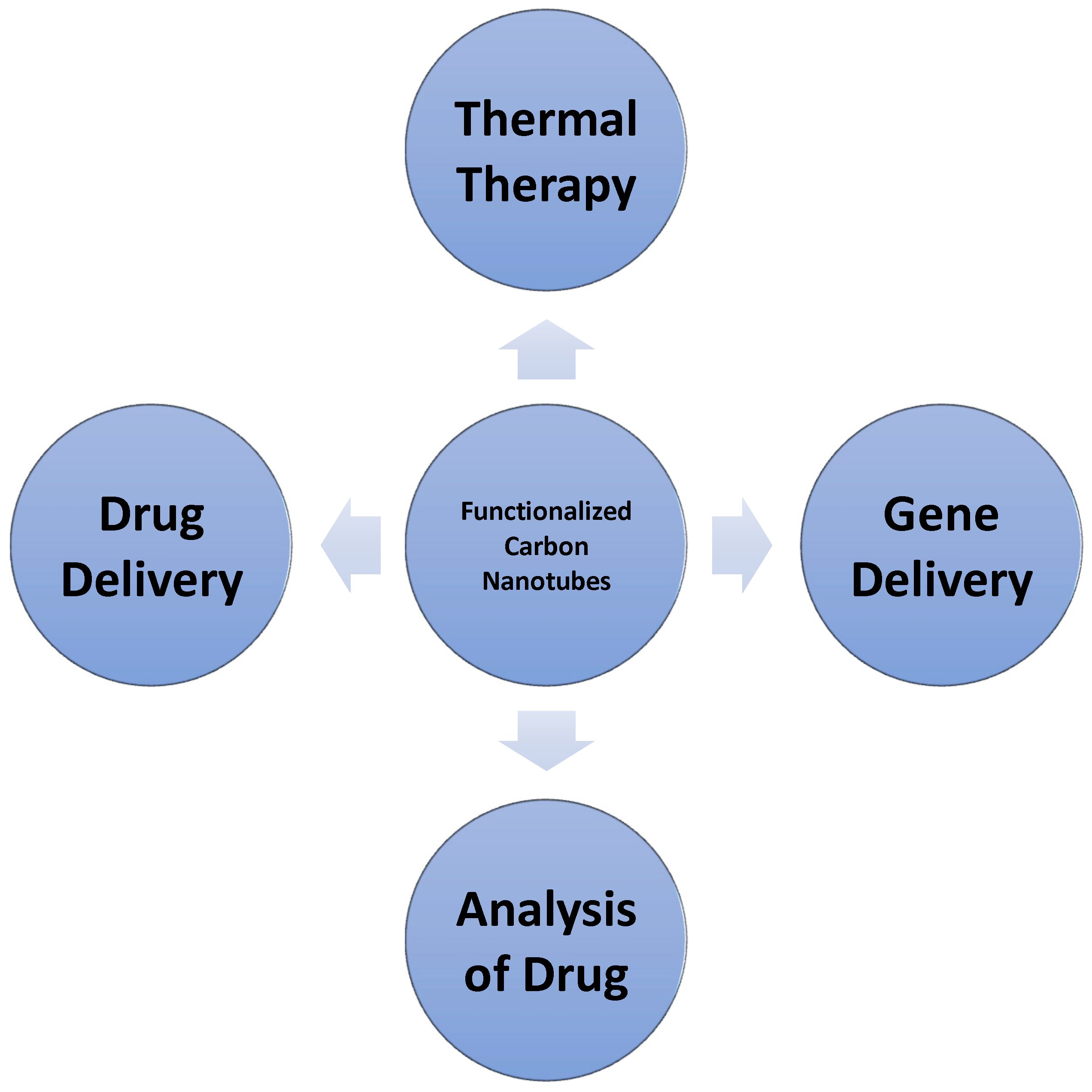
6.3. Medical Applications of CNTs
6.4. Batteries (Lithium ion Batteries) Using CNTs
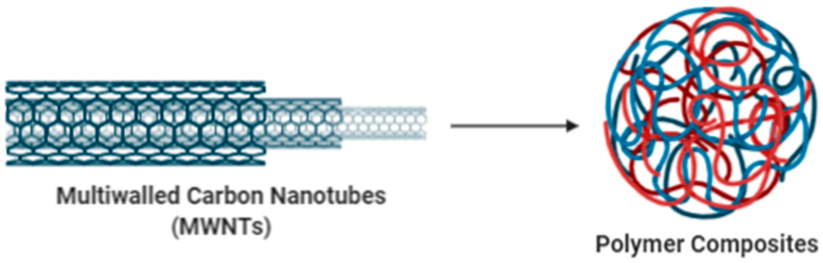
6.5. Carbon Fiber/Multi-Walled Carbon Nanotubes/Epoxy Resin Composite System
6.6. High-Performance Electromagnetic-Interference Shielding
6.7. Fouling Control and Anti-Fouling Mechanism of Polyvinylidene Fluoride Ultrafiltration Membranes
7. Characteristics of Bacterial Flagella in Comparison with Carbon Nanotubes
8. Advantages of Bacterial Flagella as Nanotubes in Comparison with Carbon Nanotubes
9. Concluding Remarks
Author Contributions
Funding
Acknowledgments
Conflicts of Interest
Copyright and Permissions
References
- Ho, B.K.X.; Azahari, B.; Yhaya, M.F.B.; Talebi, A.; Ng, C.W.C.; Tajarudin, H.A.; Ismail, N. Green technology approach for reinforcement of calcium chloride cured sodium alginate films by isolated bacteria from palm oil mill effluent (Pome). Sustainability 2020, 12, 9468. [Google Scholar] [CrossRef]
- Ng, C.W.C.; Ismail, A.F.; Makhtar, M.M.Z.; Jamaluddin, M.N.F.; Tajarudin, H.A. Conversion of food waste via two-stage fermentation to controllable chicken feed nutrients by local isolated microorganism. Int. J. Recycl. Org. Waste Agric. 2020, 9, 33–47. [Google Scholar] [CrossRef]
- Mohd, Z.M.M.; Tajarudin, H.A. Electricity generation using membrane-less microbial fuel cell powered by sludge supplemented with lignocellulosic waste. Int. J. Energy Res. 2020, 44, 3260–3265. [Google Scholar] [CrossRef]
- Othman, M.F.; Tamat, M.R.; Wan Nadiah, W.A.; Serri, N.A.; Aziz, H.A.; Tajarudin, H.A. Bioconversion of leachate to acetic and butyric acid by Clostridium butyricum NCIMB 7423 in membrane fermentor. Pertanika J. Sci. Technol. 2017, 25, 39–48. [Google Scholar]
- Aziz, H.A.; Tajarudin, H.A.; Wei, T.H.L.; Alazaiza, M.Y.D. Iron and manganese removal from groundwater using limestone filter with iron-oxidized bacteria. Int. J. Environ. Sci. Technol. 2020, 17, 2667–2680. [Google Scholar] [CrossRef]
- Terashima, H.; Kojima, S.; Homma, M. Chapter 2 Flagellar Motility in Bacteria. Structure and Function of Flagellar Motor; Elsevier Inc.: Amsterdam, The Netherlands, 2008; Volume 270, ISBN 9780123745835. [Google Scholar]
- Westerlund-Wikström, B. Peptide display on bacterial flagella: Principles and applications. Int. J. Med. Microbiol. 2000, 290, 223–230. [Google Scholar] [CrossRef]
- Lamberti, M.; Pedata, P.; Sannolo, N.; Porto, S.; De Rosa, A.; Caraglia, M. Carbon nanotubes: Properties, biomedical applications, advantages and risks in patients and occupationally-exposed workers. Int. J. Immunopathol. Pharmacol. 2015, 28, 4–13. [Google Scholar] [CrossRef]
- Haiko, J.; Westerlund-wikström, B. The Role of the Bacterial Flagellum in Adhesion and Virulence. Biology 2013, 1242–1267. [Google Scholar] [CrossRef]
- Van Gerven, N. Pili and Flagella: Biology, Structure, and Biotechnological Applications I. Introduction; Academic Press: Cambridge, MA, USA, 2011; Volume 103, ISBN 9780124159068. [Google Scholar]
- Fiedler, T.; Köller, T.; Kreikemeyer, B. Streptococcus pyogenes biofilms—Formation, biology, and clinical relevance. Front. Cell. Infect. Microbiol. 2015, 5, 15. [Google Scholar] [CrossRef]
- Subramanian, S.; Kearns, D.B. Functional Regulators of Bacterial Flagella. Annu. Rev. Microbiol. 2019, 73, 225–246. [Google Scholar] [CrossRef]
- Nakamura, S.; Minamino, T. Flagella-Driven Motility of Bacteria. Biomolecules 2019, 9, 279. [Google Scholar] [CrossRef] [PubMed]
- Kalmokoff, M.L.; Jarrell, K.F.; Koval, S.F. Isolation of flagella from the archaebacterium Methanococcus voltae by phase separation with Triton X-114. J. Bacteriol. 1988, 170, 1752–1758. [Google Scholar] [CrossRef] [PubMed]
- Echazarreta, M.A.; Klose, K.E. Vibrio Flagellar Synthesis. Front. Cell. Infect. Microbiol. 2019, 9, 131. [Google Scholar] [CrossRef] [PubMed]
- Morimoto, Y.V.; Minamino, T. Structure and Function of the Bi-Directional Bacterial Flagellar Motor. Biomolecules 2014, 4, 217–234. [Google Scholar] [CrossRef] [PubMed]
- Schuhmacher, J.S.; Thormann, K.M.; Bange, G. How bacteria maintain location and number of flagella? FEMS Microbiol. Rev. 2015, 39, 812–822. [Google Scholar] [CrossRef]
- Evans, L.D.B.; Hughes, C.; Fraser, G.M. Building a flagellum outside the bacterial cell. Trends Microbiol. 2014, 22, 566–572. [Google Scholar] [CrossRef]
- Ferooz, J.; Letesson, J.J. Morphological analysis of the sheathed flagellum of Brucella melitensis. BMC Res. Notes 2010, 3, 33320102010. [Google Scholar] [CrossRef]
- Iwazawa, J.; Imae, Y.; Kobayasi, S. Study of the torque of the bacterial flagellar motor using a rotating electric field. Biophys. J. 1959, 64, 925–933. [Google Scholar] [CrossRef]
- Mora, T.; Yu, H.; Sowa, Y.; Wingreen, N.S. Steps in the Bacterial Flagellar Motor. PLoS Comput. Biol. 2009, 5. [Google Scholar] [CrossRef]
- Nirody, J.A.; Berry, R.M.; Oster, G. The Limiting Speed of the Bacterial Flagellar Motor. Biophys. J. 2016, 111, 557–564. [Google Scholar] [CrossRef]
- Lele, P.P.; Hosu, B.G.; Berg, H.C. Dynamics of mechanosensing in the bacterial fl agellar motor. Proc. Natl. Acad. Sci. USA 2013, 110, 11839–11844. [Google Scholar] [CrossRef] [PubMed]
- Guttenplan, S.B.; Shaw, S.; Kearns, D.B. The cell biology of peritrichous flagella in Bacillus subtilis. Mol. Microbiol. 2013, 87, 211–229. [Google Scholar] [CrossRef] [PubMed]
- Imada, K. Bacterial flagellar axial structure and its construction. Biophys. Rev. 2018, 10, 559–570. [Google Scholar] [CrossRef] [PubMed]
- Selvakumar, R.; Seethalakshmi, N.; Thavamani, P.; Naidu, R.; Megharaj, M. Recent advances in the synthesis of inorganic nano/microstructures using microbial biotemplates and their applications. RSC Adv. 2014, 4, 52156–52169. [Google Scholar] [CrossRef]
- Jo, W.; Cheang, U.K.; Kim, M.J. Development of flagella bio-templated nanomaterials for electronics. Nano Converg. 2014, 1, 1–14. [Google Scholar] [CrossRef][Green Version]
- Wang, F.; Li, D.; Mao, C. Genetically modifiable flagella as templates for silica fibers: From hybrid nanotubes to 1D periodic nanohole arrays. Adv. Funct. Mater. 2008, 18, 4007–4013. [Google Scholar] [CrossRef]
- Vijayan, V.; Parasuraman, M.S.; Vasanthraj, S.; Varadharajan, R. Nanoswimmers-a Advance Tool for Medical Application. Rapp. Pharm. 2015, 1, 118–121. [Google Scholar]
- Ali, J.; Cheang, U.K.; Darvish, A.; Kim, H.; Kim, M.J. Biotemplated flagellar nanoswimmers. APL Mater. 2017, 5. [Google Scholar] [CrossRef]
- Weber, M.; Julbe, A.; Ayral, A.; Miele, P.; Bechelany, M. Atomic Layer Deposition for Membranes: Basics, Challenges, and Opportunities. Chem. Mater. 2018, 30, 7368–7390. [Google Scholar] [CrossRef]
- Li, D.; Zhu, Y.; Yang, T.; Yang, M.; Mao, C. Bacterial flagella as an osteogenic differentiation nano-promoter. Nanoscale Horiz. 2019, 4, 1286–1292. [Google Scholar] [CrossRef]
- Kim, J.W.; Tung, S. Bio-hybrid micro/nanodevices powered by flagellar motor: Challenges and strategies. Front. Bioeng. Biotechnol. 2015, 3, 1–8. [Google Scholar] [CrossRef]
- Mahltig, B.; Pastore, C. Mineral. and Ceramic Fibers; Elsevier Ltd.: Amsterdam, The Netherlands, 2018; ISBN 9780081022283. [Google Scholar]
- Mihai, M.M.; Holban, A.M.; Călugăreanu, A.; Orzan, O.A. Recent advances in diagnosis and therapy of skin cancers through nanotechnological approaches. Nanostruct. Cancer Ther. 2017, 285–305. [Google Scholar] [CrossRef]
- Khan, I.; Saeed, K.; Khan, I. Nanoparticles: Properties, applications and toxicities. Arab. J. Chem. 2019, 12, 908–931. [Google Scholar] [CrossRef]
- Dubey, G.P.; Ben-Yehuda, S. Intercellular nanotubes mediate bacterial communication. Cell 2011, 144, 590–600. [Google Scholar] [CrossRef] [PubMed]
- Hesse, W.R.; Luo, L.; Zhang, G.; Mulero, R.; Cho, J.; Kim, M.J. Mineralization of flagella for nanotube formation. Mater. Sci. Eng. C 2009, 29, 2282–2286. [Google Scholar] [CrossRef]
- Li, D.; Qu, X.; Newton, S.M.C.; Klebba, P.E.; Mao, C. Morphology-controlled synthesis of silica nanotubes through pH- and sequence-responsive morphological change of bacterial flagellar biotemplates. J. Mater. Chem. 2012, 22, 15702–15709. [Google Scholar] [CrossRef] [PubMed]
- Wu, X.; Ruan, J.; Ohsuna, T.; Terasaki, O.; Che, S. A novel route for synthesizing silica nanotubes with chiral mesoporous wall structures. Chem. Mater. 2007, 19, 1577–1583. [Google Scholar] [CrossRef]
- Hwei Leong, O.N.G.; Constanto-Poulos, K.T.; Ginic-Markovic, M.; Clarke, S. Study into the attachment of small and large silanes to carbon nanotube via click chemistry. Polym. Sci. 2019, 5, 2–4. [Google Scholar] [CrossRef]
- Ibrahim, K.S. Carbon nanotubes-properties and applications: A review. Carbon Lett. 2013, 14, 131–144. [Google Scholar] [CrossRef]
- Nguyen, B.T.; Than, X.T.; Nguyen, V.C.; Tam Ngo, T.T.; Bui, H.T.; Nguyen, X.N.; Phan, H.K.; Phan, N.M. Fabrication of horizontally aligned ultra-long single-walled carbon nanotubes on Si substrates using the fast-heating chemical vapor deposition method. Adv. Nat. Sci. Nanosci. Nanotechnol. 2012, 3. [Google Scholar] [CrossRef]
- Bacsa, R.R.; Flahaut, E.; Laurent, C.; Peigney, A.; Aloni, S.; Puech, P.; Bacsa, W.S. Narrow diameter double-wall carbon nanotubes: Synthesis, electron microscopy and inelastic light scattering. New J. Phys. 2003, 5. [Google Scholar] [CrossRef]
- Lephuthing, S.S.; Okoro, A.M.; Lesufi, M.; Ige, O.O.; Olubambi, P.A. Effect of milling parameters on the dispersion characteristics of multi-walled carbon nanotubes in transition metal oxides. IOP Conf. Ser. Mater. Sci. Eng. 2018, 430. [Google Scholar] [CrossRef]
- Chen, Z.; Zhang, A.; Wang, X.; Zhu, J.; Fan, Y.; Yu, H.; Yang, Z. The Advances of Carbon Nanotubes in Cancer Diagnostics and Therapeutics. J. Nanomater. 2017, 2017. [Google Scholar] [CrossRef]
- Utreja, P.; Jain, S.; Tiwary, K.A. Novel Drug Delivery Systems for Sustained and Targeted Delivery of Anti-Cancer Drugs: Current Status and Future Prospects. Curr. Drug Deliv. 2010, 7, 152–161. [Google Scholar] [CrossRef] [PubMed]
- Kostarelos, K.; Lacerda, L.; Pastorin, G.; Wu, W.; Wieckowski, S.; Luangsivilay, J.; Godefroy, S.; Pantarotto, D.; Briand, J.P.; Muller, S.; et al. Cellular uptake of functionalized carbon nanotubes is independent of functional group and cell type. Nat. Nanotechnol. 2007, 2, 108–113. [Google Scholar] [CrossRef] [PubMed]
- Singh, R.; Pantarotto, D.; Lacerda, L.; Pastorin, G.; Klumpp, C.; Prato, M.; Bianco, A.; Kostarelos, K. Tissue biodistribution and blood clearance rates of intravenously administered carbon nanotube radiotracers. Proc. Natl. Acad. Sci. USA 2006, 103, 3357–3362. [Google Scholar] [CrossRef]
- Faria, P.C.B.D.; Santos, L.I.D.; Coelho, J.P.; Ribeiro, H.B.; Pimenta, M.A.; Ladeira, L.O.; Gomes, D.A.; Furtado, C.A.; Gazzinelli, R.T. Oxidized multiwalled carbon nanotubes as antigen delivery system to promote superior CD8+ T Cell response and protection against Cancer. Nano Lett. 2014, 14, 5458–5470. [Google Scholar] [CrossRef]
- Shulaker, M.M.; Hills, G.; Patil, N.; Wei, H.; Chen, H.Y.; Wong, H.S.P.; Mitra, S. Carbon nanotube computer. Nature 2013, 501, 526–530. [Google Scholar] [CrossRef]
- Postma, H.W.; de Jonge, M.; Yao, Z.; Dekker, C. Electrical transport through carbon nanotube junctions created by mechanical manipulation. Phys. Rev. B Condens. Matter Mater. Phys. 2000, 62, R10653–R10656. [Google Scholar] [CrossRef]
- Anantram, M.P.; Léonard, F. Physics of carbon nanotube electronic devices. Rep. Prog. Phys. 2006, 69, 507–561. [Google Scholar] [CrossRef]
- Frackowiak, E.; Béguin, F. Electrochemical storage of energy in carbon nanotubes and nanostructured carbons. Carbon 2002, 40, 1775–1787. [Google Scholar] [CrossRef]
- Derycke, V.; Martel, R.; Appenzeller, J.; Avouris, P. Carbon Nanotube Inter- and Intramolecular Logic Gates. Nano Lett. 2001, 1, 453–456. [Google Scholar] [CrossRef]
- Collins, P.G.; Arnold, M.S.; Avouris, P. Engineering carbon nanotubes and nanotube circuits using electrical breakdown. Science 2001, 292, 706–709. [Google Scholar] [CrossRef] [PubMed]
- Yeow, J.T.W.; Wang, Y. A review of carbon nanotubes-based gas sensors. J. Sensors 2009, 2009. [Google Scholar] [CrossRef]
- Hahm, M.-G.; Hashim, D.P.; Vajtai, R.; Ajayan, P.M. A review: Controlled synthesis of vertically aligned carbon nanotubes. Carbon Lett. 2011, 12, 185–193. [Google Scholar] [CrossRef][Green Version]
- Durairaj, A.; Basak, S. Carbon Nanotubes (CNTs) Production, Characterisation and Its Applications. Int. J. Adv. Pharm. Sci. 2010, 1, 187–195. [Google Scholar] [CrossRef]
- Megahed, S.; Scrosati, B. Lithium-ion rechargeable batteries. J. Power Sources 1994, 51, 79–104. [Google Scholar] [CrossRef]
- Lithium-ion, M.; Evanoff, K.; Benson, J.; Schauer, M.; Kovalenko, I.; Lashmore, D.; Ready, W.J. Ultra Strong Silicon-Coated Carbon Nanotube Nonwoven Fabric as a Battery Anode. ACS Nano 2012, 9837–9845. [Google Scholar]
- Meunier, V.; Kephart, J.; Roland, C.; Bernholc, J. Ab Initio Investigations of Lithium Diffusion in Carbon Nanotube Systems. Phys. Rev. Lett. 2002, 88, 420022002. [Google Scholar] [CrossRef]
- Fouda, H.; Guo, L. The Mechanical Properties of CF/Epoxy Resin Composite with Adding Different Types of CNTS. Int. J. Eng. Res. Technol. 2017, 6, 311–315. [Google Scholar]
- Fouda, H.; Guo, L.; Yue, Y.; Chen, K.; Elsharkawy, K. Synthesis and Characterization of Hybrid CF/MWCNTS/Epoxy Resin Composite System. IOP Conf. Ser. Mater. Sci. Eng. 2017, 220. [Google Scholar] [CrossRef]
- Zhang, S.; Hao, A.; Nguyen, N.; Oluwalowo, A.; Liu, Z.; Dessureault, Y.; Park, J.G.; Liang, R. Carbon nanotube/carbon composite fiber with improved strength and electrical conductivity via interface engineering. Carbon 2019, 144, 628–638. [Google Scholar] [CrossRef]
- Zhao, Z.; Teng, K.; Li, N.; Li, X.; Xu, Z.; Chen, L.; Niu, J.; Fu, H.; Zhao, L.; Liu, Y. Mechanical, thermal and interfacial performances of carbon fiber reinforced composites flavored by carbon nanotube in matrix/interface. Compos. Struct. 2017, 159, 761–772. [Google Scholar] [CrossRef]
- Zhang, X.; Fan, X.; Yan, C.; Li, H.; Zhu, Y.; Li, X.; Yu, L. Interfacial Microstructure and Properties of Carbon Fiber Composites Modified with Graphene Oxide. ACS Appl. Mater. Interfaces 2012, 4, 1543–1552. [Google Scholar] [CrossRef] [PubMed]
- De Paiva, J.M.F.; De Nadai Dos Santos, A.; Rezende, M.C. Mechanical and morphological characterizations of carbon fiber fabric reinforced epoxy composites used in aeronautical field. Mater. Res. 2009, 12, 367–374. [Google Scholar] [CrossRef]
- Rawal, S.; Brantley, J.; Karabudak, N. Development of Carbon Nanotube-Based Composite for Spacecraft Components; IEEE: Piscataway Township, NJ, USA, 2013; ISBN 978-1-4673-6395-2. [Google Scholar]
- Singh, A.P.; Garg, P.; Alam, F.; Singh, K.; Mathur, R.B.; Tandon, R.P.; Chandra, A.; Dhawan, S.K. Phenolic resin-based composite sheets filled with mixtures of reduced graphene oxide, γ-Fe2O3 and carbon fibers for excellent electromagnetic interference shielding in the X-band. Carbon 2012, 50, 3868–3875. [Google Scholar] [CrossRef]
- Zhang, Q.; Wang, Y.; Zhang, B.; Zhao, K.; He, P.; Huang, B. 3D superelastic graphene aerogel-nanosheet hybrid hierarchical nanostructures as high-performance supercapacitor electrodes. Carbon 2018, 127, 449–458. [Google Scholar] [CrossRef]
- Wang, H.; Li, N.; Wang, W.; Shi, J.; Xu, Z.; Liu, L.; Hu, Y.; Jing, M.; Liu, L.; Zhang, X. Bead nano-necklace spheres on 3D carbon nanotube scaffolds for high-performance electromagnetic-interference shielding. Chem. Eng. J. 2019, 360, 1241–1246. [Google Scholar] [CrossRef]
- Zhan, Y.; Wang, J.; Zhang, K.; Li, Y.; Meng, Y.; Yan, N.; Wei, W.; Peng, F.; Xia, H. Fabrication of a flexible electromagnetic interference shielding Fe3O4@reduced graphene oxide/natural rubber composite with segregated network. Chem. Eng. J. 2018, 344, 184–193. [Google Scholar] [CrossRef]
- Wang, S.; Liang, R.; Wang, B.; Zhang, C. Dispersion and thermal conductivity of carbon nanotube composites. Carbon 2009, 47, 53–57. [Google Scholar] [CrossRef]
- Chatterjee, S.; Nafezarefi, F.; Tai, N.H.; Schlagenhauf, L.; Nüesch, F.A.; Chu, B.T.T. Size and synergy effects of nanofiller hybrids including graphene nanoplatelets and carbon nanotubes in mechanical properties of epoxy composites. Carbon 2012, 50, 5380–5386. [Google Scholar] [CrossRef]
- Zhang, J.; Xu, Z.; Shan, M.; Zhou, B.; Li, Y.; Li, B.; Niu, J.; Qian, X. Synergetic effects of oxidized carbon nanotubes and graphene oxide on fouling control and anti-fouling mechanism of polyvinylidene fluoride ultrafiltration membranes. J. Memb. Sci. 2013, 448, 81–92. [Google Scholar] [CrossRef]
- Biology, B.; Microbes, O. Basic Biology of Oral Microbes. Atlas Oral Microbiol. 2015, 1–14. [Google Scholar] [CrossRef]
- Iii, R.; Catalyzed, C.; An, P.; Pyrene-, O.S.; Hu, J.; Zhang, D.; Harris, F.W. Supporting Information for: Growth of Half-Meter Long Carbon Nanotubes Based on Schulz-Flory Distribution. J. Chem. Theory Comput. 2008, 1–13. [Google Scholar] [CrossRef]
- Dubey, G.P.; Malli Mohan, G.B.; Dubrovsky, A.; Amen, T.; Tsipshtein, S.; Rouvinski, A.; Rosenberg, A.; Kaganovich, D.; Sherman, E.; Medalia, O.; et al. Architecture and Characteristics of Bacterial Nanotubes. Dev. Cell 2016, 36, 453–461. [Google Scholar] [CrossRef]
- Ma, J.; Wang, J.N.; Wang, X.X. Large-diameter and water-dispersible single-walled carbon nanotubes: Synthesis, characterization and applications. J. Mater. Chem. 2009, 19, 3033–3041. [Google Scholar] [CrossRef]
- Jo, W.; Freedman, K.J.; Yi, D.K.; Kim, M.J. Fabrication of tunable silica-mineralized nanotubes using flagella as bio-templates. Nanotechnology 2012, 23. [Google Scholar] [CrossRef]
- Hasnain, M.S.; Nayak, A.K. Functionalization of carbon nanotubes. SpringerBriefs Appl. Sci. Technol. 2019, 21–28. [Google Scholar] [CrossRef]
- Jackson, P.; Jacobsen, N.R.; Baun, A.; Birkedal, R.; Kühnel, D.; Jensen, K.A.; Vogel, U.; Wallin, H. Bioaccumulation and ecotoxicity of carbon nanotubes. Chem. Cent. J. 2013, 7, 1–21. [Google Scholar] [CrossRef]
- Klein, Á.; Kovács, M.; Muskotál, A.; Jankovics, H.; Tóth, B.; Pósfai, M.; Vonderviszt, F. Nanobody-Displaying Flagellar Nanotubes. Sci. Rep. 2018, 8, 1–9. [Google Scholar] [CrossRef]
- Atsumi, T. An ultrasonic motor model for bacterial flagellar motors. J. Theor. Biol. 2001, 213, 31–51. [Google Scholar] [CrossRef]
- Leung, K.M.; Wanger, G.; Guo, Q.; Gorby, Y.; Southam, G.; Lau, W.M.; Yang, J. Bacterial nanowires: Conductive as silicon, soft as polymer. Soft Matter 2011, 7, 6617–6621. [Google Scholar] [CrossRef]
- Yamashita, L.; Hasegawa, K.; Suzuki, H.; Vonderviszt, F.; Mimori-Kiyosue, Y.; Namba, K. Structure and switching of bacterial flagellar filaments studied by X-ray fiber diffraction. Nat. Struct. Biol. 1998, 5, 125–132. [Google Scholar] [CrossRef]
- Lovley, D.R.; Walker, D.J.F. Geobacter Protein Nanowires. Front. Microbiol. 2019, 10. [Google Scholar] [CrossRef]
- Tan, Y.; Adhikari, R.Y.; Malvankar, N.S.; Pi, S.; Ward, J.E.; Woodard, T.L.; Nevin, K.P.; Xia, Q.; Tuominen, M.T.; Lovley, D.R. Synthetic Biological Protein Nanowires with High Conductivity. Small 2016, 12, 4481–4485. [Google Scholar] [CrossRef]
- Sure, S.; Ackland, M.L.; Torriero, A.A.J.; Adholeya, A.; Kochar, M. Microbial nanowires: An electrifying tale. Microbiology 2016, 162, 2017–2028. [Google Scholar] [CrossRef]
- Reguera, G.; McCarthy, K.D.; Mehta, T.; Nicoll, J.S.; Tuominen, M.T.; Lovley, D.R. Extracellular electron transfer via microbial nanowires. Nature 2005, 435, 1098–1101. [Google Scholar] [CrossRef]
- Gorby, Y.A.; Yanina, S.; McLean, J.S.; Rosso, K.M.; Moyles, D.; Dohnalkova, A.; Beveridge, T.J.; Chang, I.S.; Kim, B.H.; Kim, K.S.; et al. Electrically conductive bacterial nanowires produced by Shewanella oneidensis strain MR-1 and other microorganisms. Proc. Natl. Acad. Sci. USA 2006, 103, 11358–11363. [Google Scholar] [CrossRef]
- Singh, A.; Srivastava, A. Mechanical Behavior of Double-Walled Carbon Nanotubesusing Molecular Dynamics. In Proceedings of the Indian Society of Theoretical and Applied Mechanics (ISTAM-2015), MNIT, Jaipur, India, 16–19 December 2015. [Google Scholar]
- Darnton, N.C.; Berg, H.C. Force-extension measurements on bacterial flagella: Triggering polymorphic transformations. Biophys. J. 2007, 92, 2230–2236. [Google Scholar] [CrossRef]
- Wei, X.; Chen, Q.; Peng, L.M.; Cui, R.; Li, Y. Tensile loading of double-walled and triple-walled carbon nanotubes and their mechanical properties. J. Phys. Chem. C 2009, 113, 17002–17005. [Google Scholar] [CrossRef]
- Thornton, W.M. The electrical conductivity of bacteria, and the rate of sterilisation of bacteria by electric currents. Proc. R. Soc. London. Ser. B Contain. Pap. Biol. Character 1912, 85, 331–344. [Google Scholar] [CrossRef]
- Wang, Y.; Weng, G.J. Micromechanics and Nanomechanics of Composite Solids; Springer: Berlin, Germany, 2018; ISBN 9783319527949. [Google Scholar]
- Pitroda, J. A Critical Review on Carbon Nanotubes. Int. J. Constr. Res. Civ. Eng. 2016, 2, 36–42. [Google Scholar] [CrossRef]


| Type of Flagellum | Characteristics | Illustration | Reference |
|---|---|---|---|
| Monotrichous | Only a flagellum extends from one end of the cell. |  | [17] |
| Amphitrichous | A single or multiple flagella extend from both ends of the cell. |  | [17] |
| Lophotrichous | Several flagella that extend from one end of the cell. |  | [17] |
| Peritrichous | Multiple flagella that randomly distribute over the entire cell. |  | [17] |
| Application | Reference |
|---|---|
| Biotemplated Nanomaterials for Electronics | [26,27] |
| Templates for Silica Fibers | [28] |
| Nanoswimmers | [29,30] |
| Nanotubes Formation | [31] |
| Electronics | References |
|---|---|
| Dye-Sensitized Solar Cell (DSSC) | [27] |
| Lithium Ion Battery (LIB) | [27] |
| Osteogenic Differentiation Nano-Promoter | [32] |
| Bioactuator and Biosensor | [33] |
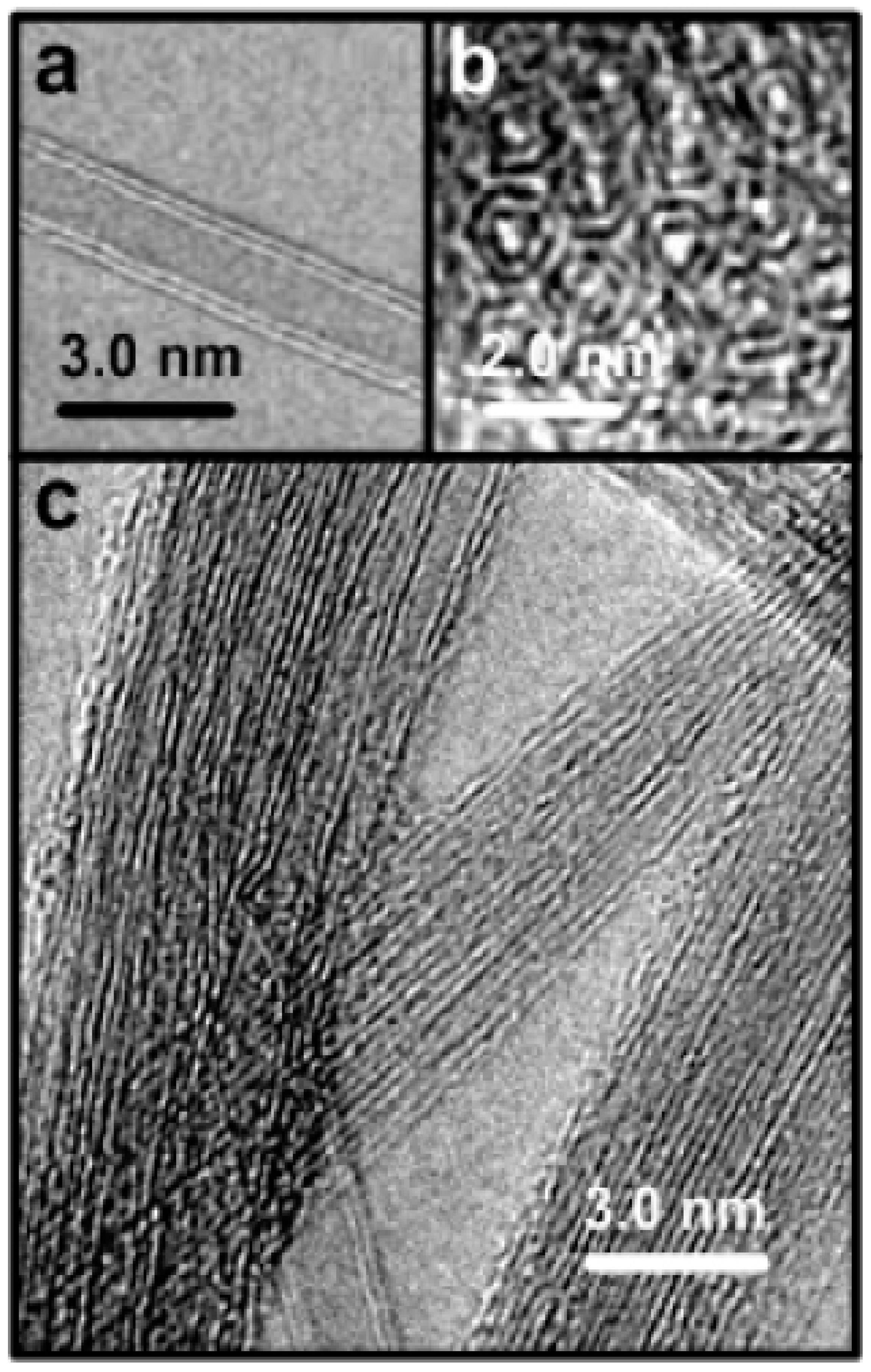
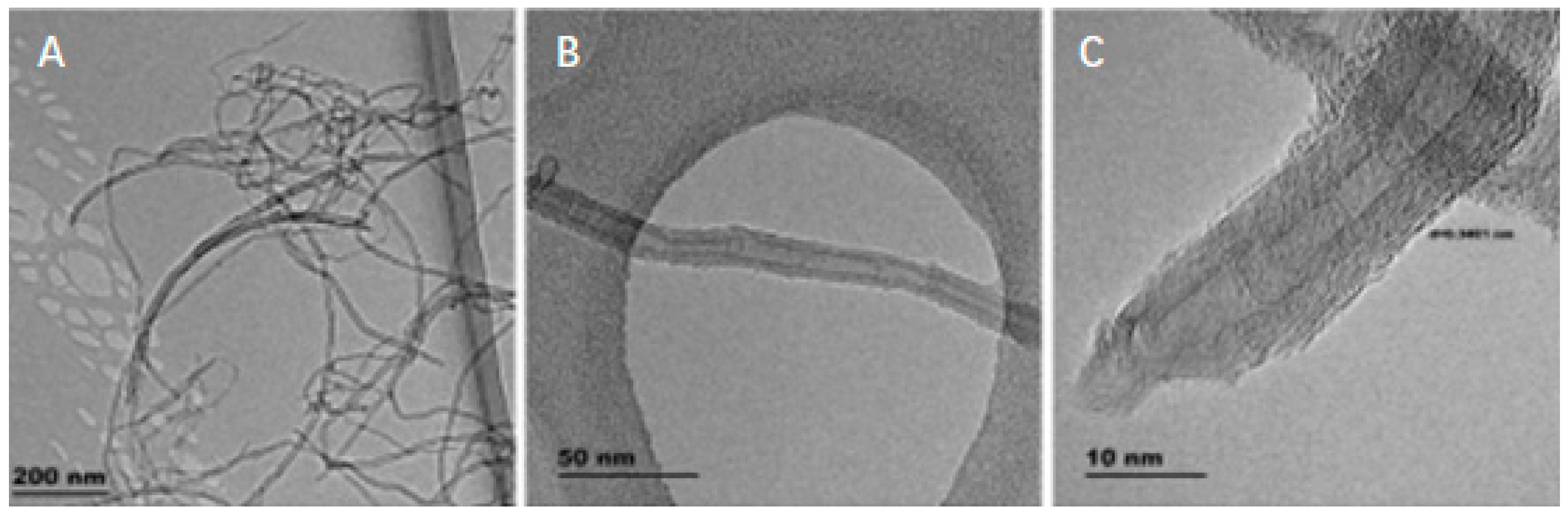
| Type of Carbon Nanotubes (CNTs) | Characteristics | Applications | Reference |
|---|---|---|---|
Single-walled CNTs (SWNTs) | A single graphene sheet rolled upon itself with a diameter of 1–2 nm. | Nanoporous filters, catalyst supports, solar collector. | [42] |
Double-walled CNTs (DWNTs) | Two concentric carbon nanotubes in which the outer tube encloses the inner tube. | Gas sensors, field emission displays, imaging and therapeutic agents. | [42] |
Multi-walled CNTs (MWNTs) | Multiple layers of graphene rolled upon itself with diameters of about 2 to 50 nm. | Catalysts, electron field emitters, sensors, nanolithography. | [42] |
| Charac-teristics/Attributes | Bacterial Flagella/(as Nanotubes) | Single-Walled Carbon Nanotubes | Double-Walled Carbon Nanotubes | Multi-Walled Carbon Nanotubes | References |
|---|---|---|---|---|---|
| Length | 5–20 μm | Vary depending on preparation method. Normally 5–30 μm. | Vary depending on preparation method. Normally 5–30 μm. | Vary depending on preparation method. Normally 10–30 μm. | [42,77] |
| Diameter | 10–30 nm | 1–2 nm | 2–4 nm | 2–50 nm | [42,77] |
| Lattice Structure | Axial (hollow) structure consists of three major parts, the basal body, the hook and the filament. | (Cylindrical and hollow) hexagonal lattice helicity Nanotubes: ropes, tubes arranged in triangular lattice with lattice parameters of a ≈ 1.7 nm and tube-tube distance ≈ 0.314 nm (for DWCNTs and MWCNTs) | [25,82] | ||
| Elastic Modulus | 1010 N/m2 | ~1 TPa | ~800 GPa | ~0.3–1 TPa | [82,93] |
| Tensile strength | 3.5 pN/μm2 (Pa) | 50–500 GPa | ~30 GPa | 10–50 GPa | [82,94,95] |
| Electrical Conductivity | 35–350 ohms/cm3 (bacteria) | 106 to 107 S/m | [96,97] | ||
| Bacterial Flagella as Nanotubes | Reference | Carbon Nanotubes | Reference |
|---|---|---|---|
| The capability to mass produce biomaterials of uniform size, cheaper production cost | [27] | The production is relatively expensive. | [98] |
| Precise structure and lower cost of production, therefore, lower cost in implementing the technology. | [27] | Expensive to implement this new technology in replacing the previous technology. | [98] |
| Surface modification functionality. | [27] | Most researchers do not understand how CNTs work. | [98] |
| Environmentally Friendly. | [27] | Environmental Risk. | [98] |
Publisher’s Note: MDPI stays neutral with regard to jurisdictional claims in published maps and institutional affiliations. |
© 2020 by the authors. Licensee MDPI, Basel, Switzerland. This article is an open access article distributed under the terms and conditions of the Creative Commons Attribution (CC BY) license (http://creativecommons.org/licenses/by/4.0/).
Share and Cite
Chun, C.N.W.; Tajarudin, H.A.; Ismail, N.; Azahari, B.; Makhtar, M.M.Z.; Yan, L.K. Bacterial Flagellum versus Carbon Nanotube: A Review Article on the Potential of Bacterial Flagellum as a Sustainable and Green Substance for the Synthesis of Nanotubes. Sustainability 2021, 13, 21. https://doi.org/10.3390/su13010021
Chun CNW, Tajarudin HA, Ismail N, Azahari B, Makhtar MMZ, Yan LK. Bacterial Flagellum versus Carbon Nanotube: A Review Article on the Potential of Bacterial Flagellum as a Sustainable and Green Substance for the Synthesis of Nanotubes. Sustainability. 2021; 13(1):21. https://doi.org/10.3390/su13010021
Chicago/Turabian StyleChun, Charles Ng Wai, Husnul Azan Tajarudin, Norli Ismail, Baharin Azahari, Muaz Mohd Zaini Makhtar, and Leong Kah Yan. 2021. "Bacterial Flagellum versus Carbon Nanotube: A Review Article on the Potential of Bacterial Flagellum as a Sustainable and Green Substance for the Synthesis of Nanotubes" Sustainability 13, no. 1: 21. https://doi.org/10.3390/su13010021
APA StyleChun, C. N. W., Tajarudin, H. A., Ismail, N., Azahari, B., Makhtar, M. M. Z., & Yan, L. K. (2021). Bacterial Flagellum versus Carbon Nanotube: A Review Article on the Potential of Bacterial Flagellum as a Sustainable and Green Substance for the Synthesis of Nanotubes. Sustainability, 13(1), 21. https://doi.org/10.3390/su13010021