1. Introduction
Box culverts, which present a similar structure to that of abutments, generally serve as connection elements between roads and between roads and bridges. Since these elements are sensitive to settlement, they should be supported by pile foundations on rigid ground so that settlement occurrence is minimized. However, the ground under the structure may settle for different reasons. Generally, ground settlement occurs owing to poor compaction. In soft soils, this phenomenon occurs owing to primary consolidation settlement, secondary residual settlement, and drying shrinkage caused by ground drying, thereby forming a cavity under the lower part of the structure. The soil from the surrounding ground that enters the generated cavity may cause damage to the pile foundation head and accelerate surrounding ground settlement. In addition, faulting can be caused by the difference between the settlement behavior of the structure and that of the ground. Consequently, different stiffnesses owing to differences between the material properties and strength of the ground and those of the structure result in inhomogeneous deformation, particularly on soft ground.
White et al. [
1] found that cavities were formed under the lower part of the bridge structure owing to the ground compression settlement and lack of backfill compaction. Briaud et al. [
2] summarized the main causes of faulting according to their order of occurrence and highlighted that the most common cause of this phenomenon was compressible ground filling, which caused cavity formation. In addition, as a consequence of cavity formation, problems have been caused by ground erosion owing to the penetration of water under the structure [
3].
Currently, as a countermeasure to the aforementioned problems, maintenance and repair are conducted by means of soil overlaying. However, the loads on continuously cracking pavement cause continued settlement of the surrounding ground and maintenance operations reduce the usability of public roads, resulting in additional economic and social costs for implementing remedial steps. Currently, the problems caused by cavity formation under structures can be addressed only by taking temporary measures when designing and constructing, both domestically and internationally.
Therefore, to prevent and reduce the problems caused by cavity formation under structures supported by pile foundations, a soil flow protector (SFP) that can be easily installed on the side of the structure has been developed and is presented herein. Generally, ground settlement is accompanied by a downward movement of approximately the same magnitude. The SFP can prevent the rapid filling of the cavity with surrounding ground soil by continuously blocking the inflow of soil caused by ground settlement. Preventing rapid ground settlement can lead to long-term structural stability and prevent the occurrence of life-threatening damage, thereby helping to maintain and build a sustainable urban infrastructure.
Since there is no field case to which the SFP proposed in this paper has been applied, a case study through field experiments was performed. In this study, an SFP was installed on the side of a box structure supported by a pile foundation on soft ground, and a field test was performed. The displacements of the SFP and the ground were measured over a test duration of approximately one year for sections with and without SFPs to assess the effects of SFP installation. In addition, numerical analysis was performed using a commercial program, Plaxis 2D, to simulate a field test and back analysis. From these results, the behavior of the ground on which the SFP was installed was analyzed. In addition, the field test and numerical analysis results were comprehensively analyzed, and the earth pressure stability of the SFP was assessed. It was concluded that the developed SFP is suitable for reducing soft ground settlement caused by cavity formation under box structures supported by pile foundations.
2. Soil Flow Protector
2.1. Cases of Cavity Formation and Inhomogeneous Deformation
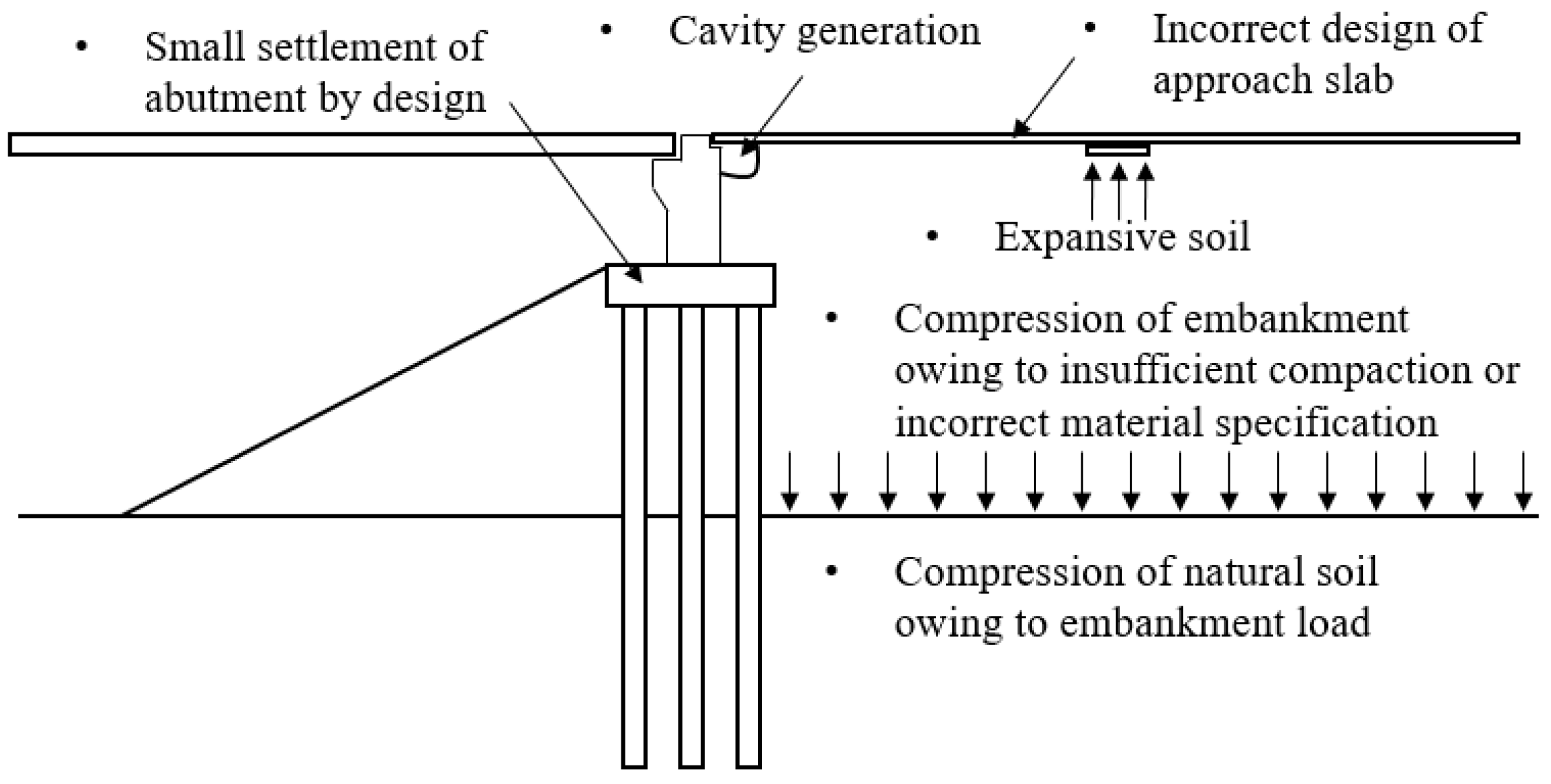
Briaud et al. [
4] reported the causes of ground settlement in pile-foundation-supported structures; in
Figure 1, an abutment is shown as an example. The causes of ground settlement were investigated by using an abutment designed to be sensitive to settlement and considering the compression of the ground owing to compressive embankment loading, the use of short access slabs owing to design errors, and defects in backfill materials such as inflatable soil. The problems generated by these causes are shown in
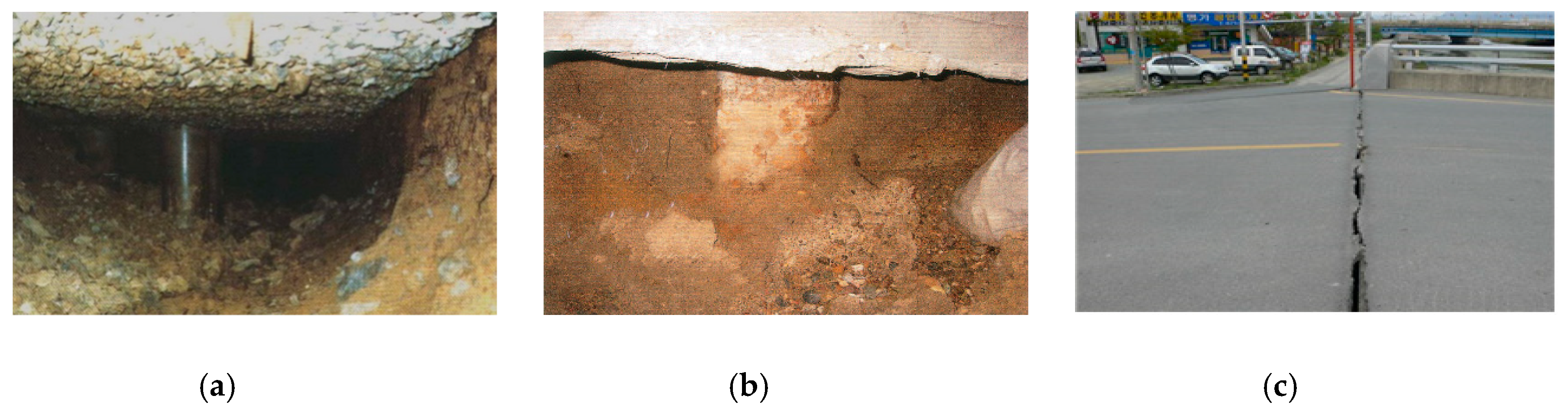
Figure 2; i.e., a cavity is formed under the structure and groundwater accumulates (
Figure 2a), corrosion occurs in pile foundations owing to the inflow of groundwater (
Figure 2b), and cracks can appear owing to settlement differences at the connection point between the road and the bridge (
Figure 2c).
2.2. Principle of the Soil Flow Protector
The problems caused by the formation of cavities under structures are shown in
Figure 3a; vehicle drivability and stability decrease owing to cracking and breakage of pavement, pile heads are damaged owing to the inflow of soil from the surrounding ground, and uneven settlement of the structure occurs. A countermeasure against these problems involves installing an SFP on the side of the structure, as shown in
Figure 3b; even if cavities are formed owing to the aforementioned causes, the SFP secures stability by reducing the settlement and preventing pile head damage by soil, by preventing the surrounding soil from entering the cavity.
3. Field Experiment Preparation
3.1. Experimental Setup
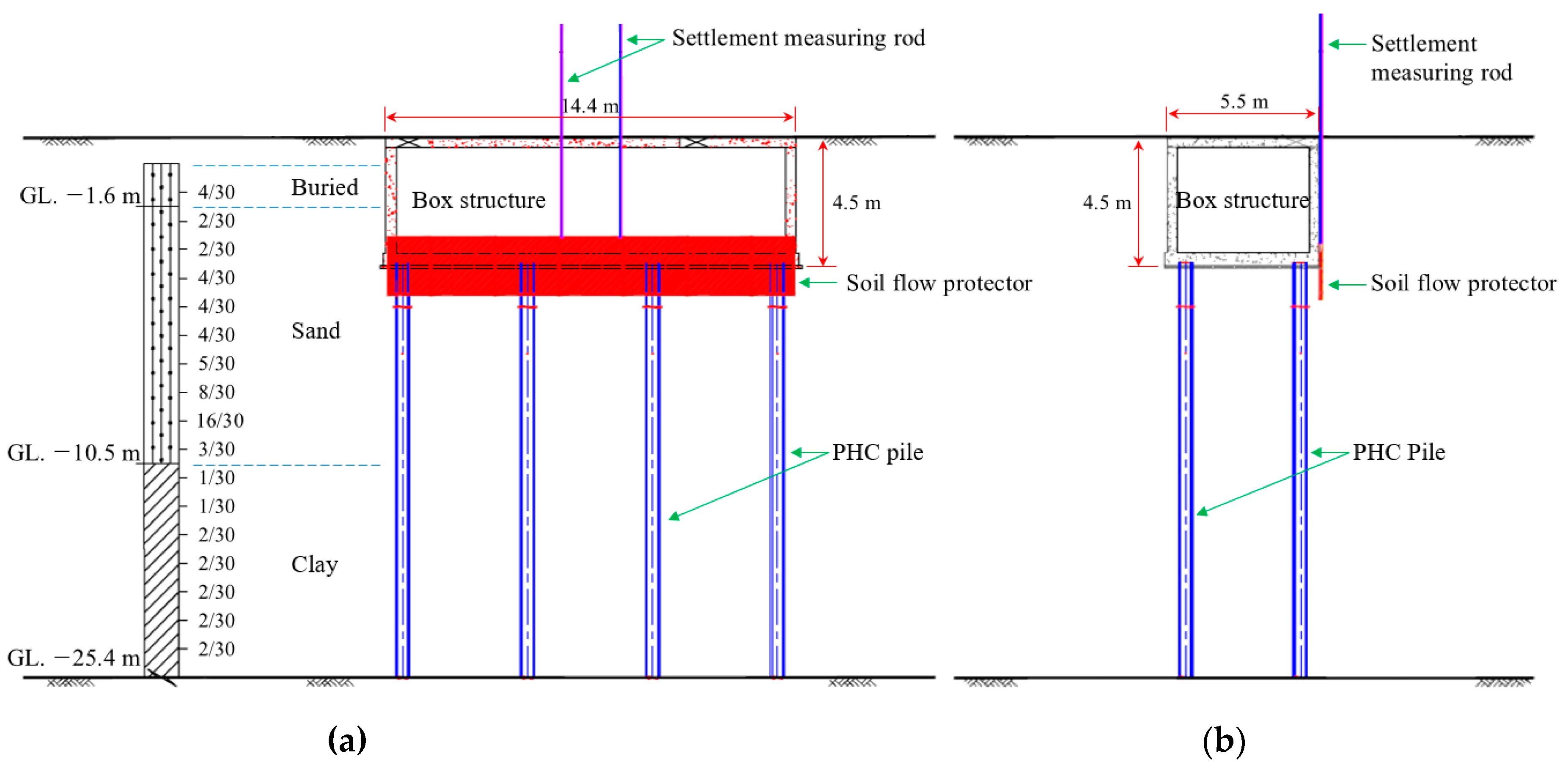
Figure 4 illustrates the experimental setup for the field test; the ground is divided into a reclamation layer, a sand layer, and a clay layer, with thicknesses of 1.6, 8.9, and 14.9 m, respectively. Under the unified soil classification system, the reclamation layer and sand layer corresponded to sand with silt (SM), and the clay layer to low-plasticity clay (CL). The material properties of field soils obtained from laboratory tests are shown in
Table 1. The dimensions of the box structure were 14.4 m (width), 5.5 m (length), and 4.5 m (height), and the lower foundation of the structure was supported by eight high-strength concrete (PHC) piles to prevent settlement.
3.2. Experimental Equipment
3.2.1. Soil Flow Protector
The SFP should have sufficient stiffness to resist the earth pressure. Therefore, as shown in
Figure 5a, steel deck panels (model: 6-1-A lining board) similar to those used at the openings of subway tunnels and underground roads were employed. The size and weight of each panel were 750 × 1990 × 200 mm and 0.28 tons, respectively. First, three deck plates were joined by welding on the ground and installed at the side of the structure. Then, another set of three panels was welded to the previously mentioned panels. An additional 300-mm-high triangular portion was constructed on the lower section to easily penetrate the ground, as shown in
Figure 5b. Two rods were installed at the center of the upper left and right sides of the SFP for measuring the settlement rate. A protective tube was additionally installed around the rods to prevent damage.
3.2.2. Measuring Equipment
To analyze the differences in settlement and horizontal displacement with and without the SFP, two settlement plates (SP-1, -2) and two inclinometers (I-1, -2) were installed at a distance of 1.0 m from the box structure, as shown in
Figure 6.
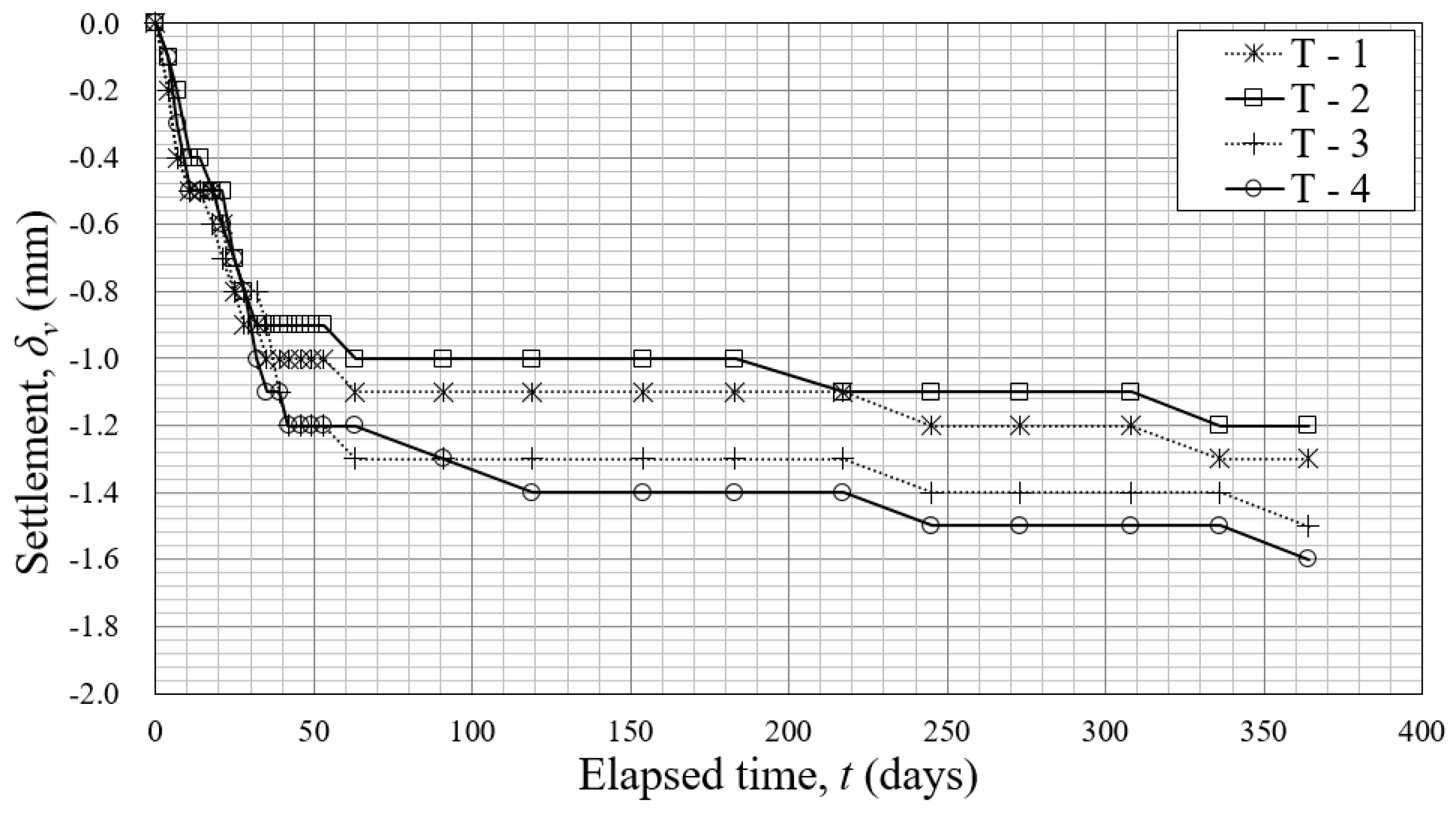
In most cases, the experimental group and the control group should be established on different box structures in field experiments. However, owing to the difficulty in securing a site in an adjacent area and to various ground conditions, the same box structure was used to define the sections with and without the SFP. Target points (T-1, -2, -3, -4) for measuring the settlement were installed on each of the four corners of the upper box structure to consider the displacement differences caused by the rotation of the box structure.
Table 2 summarizes the symbols used herein to refer to the measuring instruments used to assess the behavior of the SFP, structures, and soil during the field tests. The measurement commenced after backfilling (after all the ground instruments had been installed); measurements were performed twice a week for the first two months and once a month for approximately one year.
3.3. Experimental Method
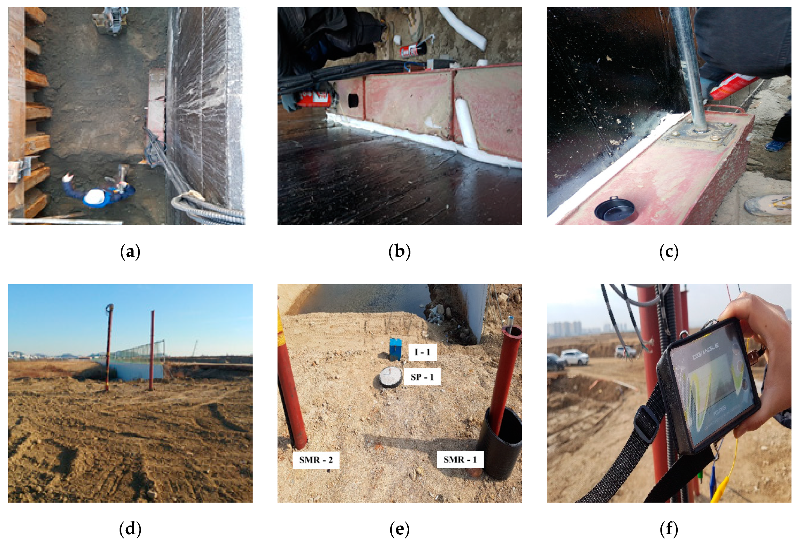
The process for SFP stability analysis involved the following six steps (
Figure 7). (a) The SFP was installed on the side of the structure; at that time, the structure and the SFP were not directly connected. (b) After the additional panels of the SFP were installed and welded together, the space between the structure and the SFP was filled with urethane foam to minimize soil penetration, thus preventing the enlargement of this space. (c) The settlement measuring rods were installed along the SFP and the surrounding ground backfill in the vertical direction; this operation was performed during backfilling. (d) After backfilling, the settlement measuring rods were connected to the ground. (e) The settlement plates, inclinometers, and settlement targets for displacement measurement were installed. (f) Measurements were performed.
4. Numerical Analysis Modeling
Cavity formation and settlement can be studied by the application of empirical data, by performing calculations using analytical methods, or by employing simulation techniques featuring numerical analysis models [
6]. In this paper, only empirical and numerical analysis techniques have been presented so far, with empirical methods including experiments on laboratory-scale models and field tests on prototype models. As numerical analysis techniques are also available for the analysis of complex structures and ground exhibiting nonlinear behavior, in this study, back analysis of the field test results was performed to define suitable design parameters by analyzing the suitability and sensitivity of modeling. In addition, the behavior of the ground where the SFP was installed was simulated, the results of the field tests and numerical analysis were synthetically analyzed, and the earth pressure stability of the SFP was assessed.
4.1. Design Parameters
To analyze ground behavior through numerical analysis, the boundary conditions and soil parameters of the analyzed model had to be determined. In particular, the soil parameters are the main input values that determine the inherent characteristics of the ground.
Figure 8 presents the initial soil parameters of each layer. The initial values for wet unit weight (
γt), cohesion (
c), internal friction angle (
φ), compression index (
Cc), swelling index (
Cs), and initial void ratio (
e0) for each layer were calculated through laboratory tests, and the values for modulus of deformation (
Es) and Poisson’s ratio (υ) were assumed from
N-values taken from existing literature [
7,
8,
9].
For the analysis, the hardening soil model (HS model) and the Mohr–Coulomb model (M–C model) were used for the landfill layer, the sand layer, and the bedrock layer; the HS model, the M–C model, and the soft soil model (SS model) were used for the clay layer. Based on these models, back analysis was performed.
The steel deck plates of the SFP were simulated using the parameters presented in
Table 3, i.e., using a thickness (
d), unit weight (
γ), and modulus of elasticity (
E) of 200 mm, 78.5 kN/m
3, and 2.0 × 10
8 kN/m
2, respectively.
4.2. Modeling
4.2.1. Suitability of Modeling
For numerical analysis, a two-dimensional (2D) mesh was created, with the
x-axis parallel to the soil layer and the
y-axis in the depth direction. The box structure supported by the pile foundation was modeled as shown in
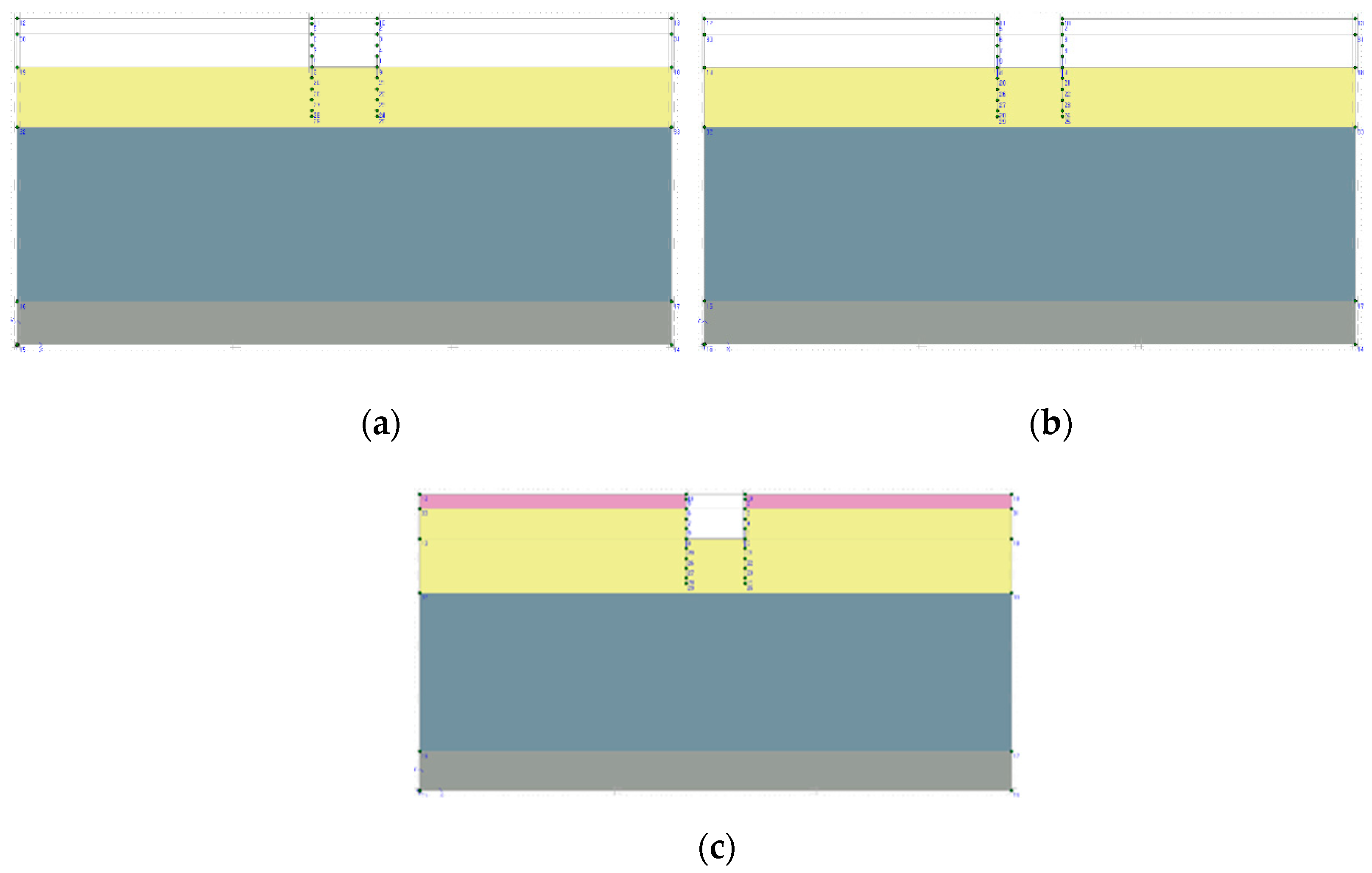
Figure 9. When simulating piles as plate elements and geometry elements in 2D analysis, they are modeled as planar walls. As shown in
Figure 9a,b, ground settlement caused by consolidation does not occur under the box structure; therefore, the behavior of ground settlement for the pile foundation cannot be simulated. In consequence, this phenomenon was modeled using an open box, as shown in
Figure 9c, so that settlement caused by the weight of the box structure itself would not occur, but at the same time, settlement at the lower part of the box structure caused by consolidation would occur. In addition, to prevent the collapse of the surrounding ground, the box structure was modeled by constraining the horizontal displacement at the wall.
The finite element analysis process, which is illustrated in
Figure 10, was conducted in the following order: (a) initial state definition, (b) installation of the SFP, and (c) backfilling.
4.2.2. Suitability of the Models Used
In general, results vary depending on the constitutive model used for numerical analysis [
10,
11,
12]. We attempted to select the most suitable numerical analysis model for ground behavior under the influence of the SFP. The HS, M–C, and SS models are generally used for this purpose, and they can be employed for numerical analysis by inputting relatively simple soil parameters. The back analysis performed in this study was based on SFP settlement data from the field tests and ground settlement on the side of the box structure.
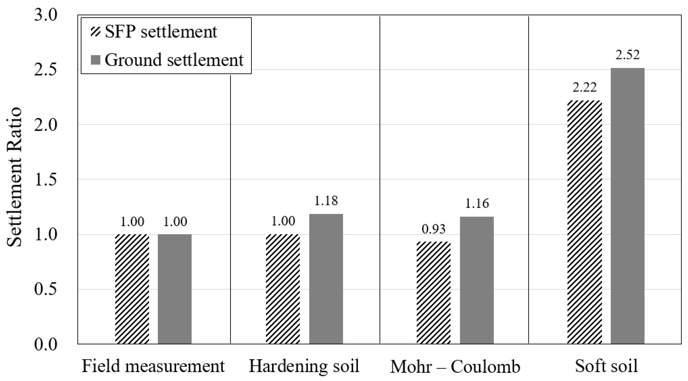
The location where the field experiments were performed presented a significantly thick clay layer; therefore, this was expected to present a significant impact on settlement. Therefore, conformity analysis was performed specially according to the constitutive model based on the settlement of the clay layer after approximately one year.
Figure 11 shows the results of numerical analysis based on the clay layer model. According to these results, for the SS model, SFP settlement and ground settlement were 2.22 times and 2.52 times the respective values obtained from the field tests, indicating that this model was not suitable for simulating settlement behavior. Additionally, in the M–C model and HS model, the SFP settlement was 0.93 times and 1.0 times the value obtained from the field tests, respectively; the ground settlement values for the former and latter methods were 1.16 times and 1.18 times the value obtained from the field tests, respectively. As the HS model was more accurate than the M–C model, it was applied to the clay layer.
4.2.3. Sensitivity Analysis of Soil Parameters
As mentioned above, the clay layer presented a significant thickness and was expected to greatly affect the settlement behavior of the ground. Therefore, after analyzing sensitivity in the clay layer, sensitivity analysis was performed on the sand and landfill layers.
The typical factors used in HS models are wet unit weight (γt), cohesion (c), internal friction angle (φ), reference secant stiffness from the drained triaxial test (E50ref), reference tangent stiffness for oedometer primary loading (Eoedref), and reference unloading/reloading stiffness (Eurref). For accurate analysis, it is required to perform tests directly related to strain coefficients. However, as the purpose of this study was to identify differences between numerical analysis results and field test results for ground settlement and soil behavior owing to SFP installation, it was assumed that E50ref = Es, E50ref ≈ Eoedref, and E50ref ≈ 3Eurref, using recommended values from the program’s manual.
According to
Figure 12a, it was found that
γt,
c, and
φ induced differences of up to 6.6%, 4.3%, and 11.3% on the settlement, respectively, whereas
Es induced a difference of up to 53.4%, i.e., the settlement of the clay layer changed the most with
Es.
Figure 12b presents similar results to those shown in
Figure 12a. Therefore, the
Es value of the clay layer, which has the greatest influence on the settlement, was changed first. Then, the next most influential factor was changed. It was found that, except for the settlement in the clay layer, the sand layer affects the ground and SFP settlement, and the landfill layer only affects the ground settlement. Back analysis was performed based on the settlement of the surrounding ground. The parameters redefined through the sensitivity analysis are shown in
Table 4.
5. Experimental and Numerical Analysis Results
5.1. Experimental Results and Analysis
5.1.1. Settlement Results and Analysis
The settlement results for the box structure supported by piles are shown in
Figure 13. Settlement at the SFP location was, on average, 1.2 mm, whereas that at the location without the SFP was, on average, 1.5 mm. It was assumed that no experimental error was caused by rotation because the slope of the box structure was found to be relatively small (approximately 0.027%).
Figure 14 shows the settlement measurement results with and without the SFP over time. The settlement in the area where the SFP was installed was 101.6 mm, and that in the area without the SFP was 129.3 mm. Therefore, by installing the SFP, surface settlement decreased by 21.4%. Moreover, it was found that the installed SFP could effectively reduce the settlement of the ground surrounding the box structure.
5.1.2. Horizontal Displacement of the Ground
Figure 15 shows the displacement measurement results over time. The maximum horizontal displacement was 2.19 mm where the SFP was installed (I-1) and 22.59 mm where the SFP was not installed (I-2). Additionally,
Figure 16 shows the surface cracks observed after approximately four months of field measurements. The crack measured about 3mm and was measured 10 times at 30cm intervals (
Figure 16c). In the section with the SFP, the maximum value, mean value, and standard deviation value of the crack width were 3 mm, 2.5 mm, and 0.67, respectively. In the section without the SFP, those of the crack width were 11 mm, 8.7 mm, and 2.1, respectively. Therefore, the installation of the SFP reduced ground settlement and horizontal displacement by providing a more stable ground behavior than that of the section without the SFP. The reduction in horizontal displacement caused by the installation of the SFP is immensely helpful in preserving the social infrastructure in the long term because it reduces the damage to the superstructure and upper road.
5.2. Numerical Analysis Results
5.2.1. Settlement of the Soil Flow Protector
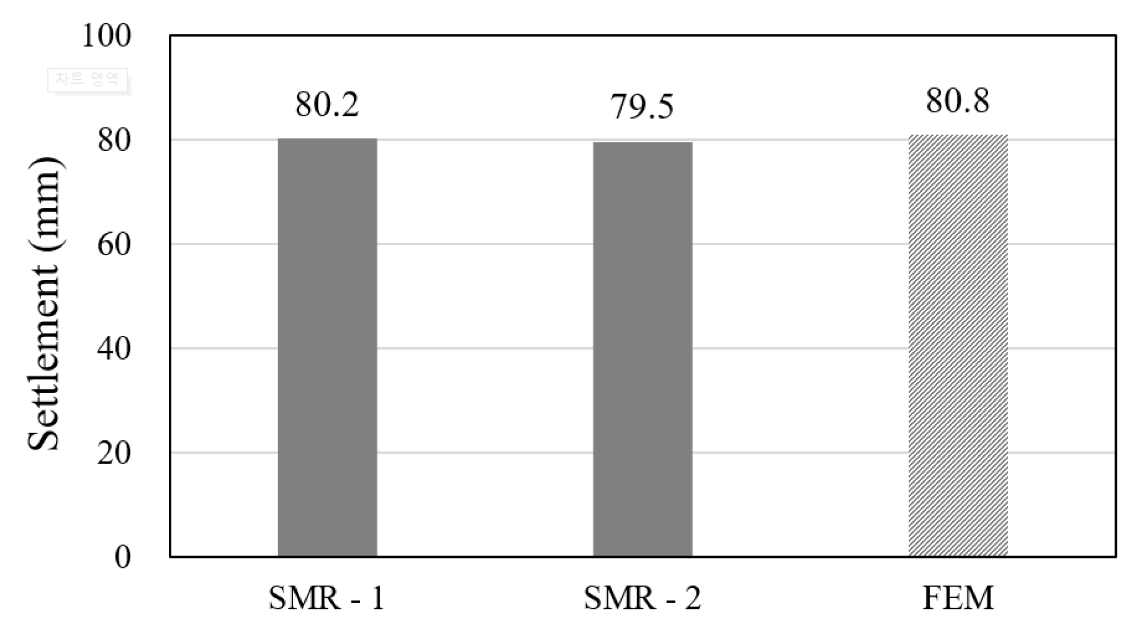
The SFP settlement values obtained via field experiments (SMR-1, -2) and numerical analysis (finite element method, FEM) are shown in
Figure 17. The actual settlement of the SFP was 79.9 mm, on average, and the calculated value from numerical analysis was 80.8 mm, resulting in a relatively small difference of approximately 1% or less.
5.2.2. Effect of SFP Installation on Ground Behavior
The field test and numerical analysis results related to the effect of SFP installation on ground behavior are shown in
Figure 18. A comparison of the field experiment and FEM results shows that the difference in SFP settlement was 16% in the SP-1 section with SFP and 23% in the SP-2 section without SFP. The difference in the settlement analysis results appears to have been caused by the differences between the field experiments and numerical analysis. In the field experiments, the results are derived from the complex correlations between the factors that constitute the various and uncertain ground layers and the errors from the measuring instruments. However, in the numerical analysis, factors such as clearly defined and homogeneous soil conditions are derived from mathematical calculations. Nevertheless, the results showed that ground settlement with SFP installation presented similar decreasing tendencies for both methods.
5.2.3. Earth Pressure Stability Analysis
As the SFP is a newly developed device, there is a lack of practical application cases for it. Therefore, design criteria and installation methods are required for the field application of this device. In consequence, it is of significant importance to analyze the actual behavior of the SFP by concurrently analyzing the earth pressure acting on it and the deformation produced. However, this study has the limitation that the actual behavior of the SFP and earth pressure could not be measured owing to the failure of the strain gauge and the earth pressure gauge installed at the SFP for the field experiments. Therefore, earth pressure stability was analyzed from the SFP behavior data collected by the inclinometer and obtained via numerical analysis.
First, the upper and lower parts of the SFP were divided based on the lower edge of the structure; the surrounding ground was set as the front side, and the structure side was set as the rear side. The results of the inclinometer presented in
Figure 19a show that the slope of the depth–lateral displacement curve at the upper front part of the SFP is lower than that at the lower face of the SFP. The numerical analysis results presented in
Figure 19b show that displacement occurred outside the structure at the top of the SFP and under the structure at the bottom. The earth pressure acting on the SFP initially penetrated the ground and changed as the settlement proceeded, generating active earth pressures at the lower front part of the SFP and passive earth pressures at the back of the SFP. However, at the upper front part of the SFP, the earth pressure generated was assumed to be zero because the ground movement direction and the SFP movement direction were the same.
A schematic of the earth pressure stability analysis for the SFP is shown in
Figure 20. The safety factor (
Fs) was calculated by considering active earth pressure at the front lower part of the SFP, passive earth pressure at the back of the SFP, and embankment loading at the front upper part of the SFP. A safety factor of 1.2 was used for examining the penetration design of the retaining wall [
13]. As a result, for a 79.9-mm settlement, the safety factor was 1.315, which remained stable even when the settlement reached 345 mm.
6. Conclusions
In this study, field experiments and numerical analysis were performed to analyze the effects of the developed SFP on ground settlement reduction and structural stability, as the installation of an SFP could be a solution for the problems caused by cavity formation under box structures supported by pile foundations on soft ground. The conclusions drawn are as follows.
- (1)
From the results of field tests, ground settlement at the section where the SFP was installed was observed to be reduced by 21.4%. In addition, the displacement measurements of the inclinometer indicated maximum horizontal displacements of 2.19 and 22.59 mm at the sections with and without the SFP, respectively. Moreover, the width of the cracks generated on the ground surface was reduced from 11 to 3 mm by SFP installation. These results show that the installation of an SFP is an effective method for reducing ground settlement, ground horizontal displacement, and surface crack width.
- (2)
According to the suitability analysis results, it was found that the HS model exhibited the most similar settlement behavior to that observed in the field test, and sensitivity analysis showed that the variation of settlement was the highest when the clay layer value was varied. From the results of the numerical analysis, it was found that the ground settlement reduced after SFP installation. SFPs are therefore expected to be of considerable help in reducing damage to many structures and social facilities located above the ground.
- (3)
The initial earth pressure acting on the SFP corresponded to static earth pressure at rest. However, when settlement occurred, it was assumed that the front lower part of the SFP experienced active earth pressure, the back of the SFP experienced passive earth pressure, and the earth pressure at the front upper part of the SFP was zero. Therefore, the safety factor (Fs) was calculated by considering active earth pressure at the front lower part of the SFP, passive earth pressure at the back of the SFP, and ground load at the front upper part of the SFP. From the analysis, it was observed that when the settlement was 79.9 mm, the safety factor was 1.315, which is greater than the standard safety factor of 1.2.
- (4)
In this study, limitations arose when analyzing the effects of earth pressure stability on the SFP through field tests and numerical analysis on specific soils. In the future, we will analyze these effects by performing additional analyses for various ground conditions. We also intend to evaluate the behavior of the ground and structure during an earthquake for the proposed SFP.
Author Contributions
Conceptualization and methodology, J.Y.; investigation and analysis, J.Y., S.S., and S.K.; writing—original draft preparation, J.Y., S.S., and S.K.; writing—review and editing, J.Y., S.S., and S.K.; All authors have read and agreed to the published version of the manuscript.
Funding
This research was funded by the Basic Science Research Program of the National Research Foundation of Korea (NRF) funded by the Ministry of Education (NRF-2018R1D1A1B07048553).
Conflicts of Interest
The authors declare no conflict of interest.
References
- White, D.J.; Mekkawy, M.M.; Sritharan, S.; Suleiman, M.T. “Underlying” causes for settlement of bridge approach pavement systems. J. Perform. Constr. Facil. 2007, 21, 273–282. [Google Scholar] [CrossRef]
- Briaud, J.; James, R.; Hoffman, S. Settlement of Bridge Approaches (The Bump at the End of the Bridge). In NCHRP Synthesis of Highway Practice 234; Transportation Research Board: Washington, DC, USA, 1997. [Google Scholar]
- Hearn, G. Synthesis on Faulted Pavements at Bridge Abutments, Report No. CDOT-DTD-97-11; Colorado Department of Transportation: Denver, CO, USA, 1997.
- Briaud, J.L.; Maher, S.F.; James, R.W. Bump at the end of the bridge. Civ. Eng. 1997, 67, 68–69. [Google Scholar]
- Yoo, J.-W.; Seo, M.-S.; Son, S.-W.; Im, J.-C. An Experimental Study on the Estimation of Optimum Length of Soil Flow Protector with Wall Stiffness. J. Korean Soc. Civ. Eng. 2019, 39, 789–799. [Google Scholar] [CrossRef]
- Suchowerska, A.M.; Merifield, R.S.; Carter, J.P.; Clausen, J. Prediction of underground cavity roof collapse using the Hoek–Brown failure criterion. Comput. Geotech. 2012, 44, 93–103. [Google Scholar] [CrossRef]
- Bowles, J.E. Foundation Analysis and Design; McGraw Hill Book Company: New York, NY, USA, 1988. [Google Scholar]
- Das, B.M. Advanced Soil Mechanics; CRC Press: New York, NY, USA, 2013. [Google Scholar]
- Hunt, R.E. Geotechnical Engineering Investigation Handbook; CRC Press: New York, NY, USA, 2005. [Google Scholar]
- Hwang, S.-P.; Im, J.-C.; Kwon, J.-G.; Kang, Y.-I.; Joo, I.-G. A Study on a Compression Index for Settlement Analysis of SCP Treated Ground Using Back Analysis. J. Korean Geoenviron. Soc. 2010, 11, 5–14. [Google Scholar]
- Surarak, C.; Likitlersuang, S.; Wanatowski, D.; Balasubramaniam, A.; Oh, E.; Guan, H. Stiffness and strength parameters for hardening soil model of soft and stiff Bangkok clays. Soils Found. 2012, 52, 682–697. [Google Scholar] [CrossRef]
- Zain, M.N.; Ahmad, J.; Ashaari, Y.; Shaffie, E.; Mustaffa, N. Modelling of Lateral Movement in Soft Soil Using Hardening Soil Model. In Proceedings of the 2011 UkSim 13th International Conference on Computer Modelling and Simulation, Cambridge, UK, 30 March–1 April 2011; pp. 195–200. [Google Scholar]
- Gere, J.M.; Goodno, B.J. Mechanics of Materials, 8th ed.; Cengage Learning: Stamford, CT, USA, 2012. [Google Scholar]
Figure 1.
Settlement of an approach slab at a bridge and embankment joining area [
4].
Figure 1.
Settlement of an approach slab at a bridge and embankment joining area [
4].
Figure 2.
Problems caused by settlement differences between the structure supported by a pile foundation and the surrounding ground: (
a) cavity generation [
5]; (
b) corrosion of pile foundation [
1]; (
c) pavement crack owing to approach slab failure [
5].
Figure 2.
Problems caused by settlement differences between the structure supported by a pile foundation and the surrounding ground: (
a) cavity generation [
5]; (
b) corrosion of pile foundation [
1]; (
c) pavement crack owing to approach slab failure [
5].
Figure 3.
Principle of the soil flow protector (SFP) as a countermeasure against cavity-formation-related problems [
5]: (
a) without SFP; (
b) with SFP.
Figure 3.
Principle of the soil flow protector (SFP) as a countermeasure against cavity-formation-related problems [
5]: (
a) without SFP; (
b) with SFP.
Figure 4.
Field experiment: (a) front view; (b) side view.
Figure 4.
Field experiment: (a) front view; (b) side view.
Figure 5.
Specifications of the SFP: (a) road deck panels used for constructing the SFP; (b) schematic of the SFP.
Figure 5.
Specifications of the SFP: (a) road deck panels used for constructing the SFP; (b) schematic of the SFP.
Figure 6.
Installation position of measuring instruments.
Figure 6.
Installation position of measuring instruments.
Figure 7.
Field experiment steps: (a) installation of the SFP; (b) SFP additional panel installation and welding; (c) installation of the settlement measuring rods and backfilling; (d) backfilling completion; (e) installation of settlement plates, inclinometers, and settlement targets for displacement measurement; (f) measurement after installation of the measuring instruments.
Figure 8.
Geologic column used in the finite element analysis.
Figure 8.
Geologic column used in the finite element analysis.
Figure 9.
Ground behavior under modeling conditions: (a) plate element; (b) geometry element; (c) open box with horizontal fixities.
Figure 9.
Ground behavior under modeling conditions: (a) plate element; (b) geometry element; (c) open box with horizontal fixities.
Figure 10.
Finite element analysis process: (a) initial state (plate element); (b) installation of the SFP (geometry element); (c) backfill (open box).
Figure 10.
Finite element analysis process: (a) initial state (plate element); (b) installation of the SFP (geometry element); (c) backfill (open box).
Figure 11.
Ratio of settlement for different finite element analysis (FEA) models.
Figure 11.
Ratio of settlement for different finite element analysis (FEA) models.
Figure 12.
Sensitivity analysis results: (a) ground settlement; (b) SFP settlement.
Figure 12.
Sensitivity analysis results: (a) ground settlement; (b) SFP settlement.
Figure 13.
Settlement of the box structure over time.
Figure 13.
Settlement of the box structure over time.
Figure 14.
Settlement of the settlement plates with and without the SFP over time.
Figure 14.
Settlement of the settlement plates with and without the SFP over time.
Figure 15.
Inclinometer results: (a) with SFP; (b) without SFP; (c) after one year of measurements.
Figure 15.
Inclinometer results: (a) with SFP; (b) without SFP; (c) after one year of measurements.
Figure 16.
Surface cracks: (a) with installation of the SFP (crack width ≈ 3 mm); (b) without installation of the SFP (crack width ≈ 11 mm); (c) crack measurement on site.
Figure 16.
Surface cracks: (a) with installation of the SFP (crack width ≈ 3 mm); (b) without installation of the SFP (crack width ≈ 11 mm); (c) crack measurement on site.
Figure 17.
SFP settlement results from field experiments and the numerical analysis.
Figure 17.
SFP settlement results from field experiments and the numerical analysis.
Figure 18.
Ground settlement results from field experiments and the FEM.
Figure 18.
Ground settlement results from field experiments and the FEM.
Figure 19.
Displacement behavior of the ground: (a) inclinometer results; (b) FEM results.
Figure 19.
Displacement behavior of the ground: (a) inclinometer results; (b) FEM results.
Figure 20.
Types of earth pressure acting on the SFP. PP: passive pressure. Pa: active pressure.
Figure 20.
Types of earth pressure acting on the SFP. PP: passive pressure. Pa: active pressure.
Table 1.
Soil physical properties and particle size distribution.
Table 1.
Soil physical properties and particle size distribution.
| Material | USCS | Water Content,
ωn (%) | Liquid Limit,
LL (%) | Plasticity Index,
PI | Specific Gravity,
Gs | D10 | D30 | D60 | Grain Size Distribution, % Passing |
|---|
| 4.75 mm | 0.075 mm | 0.005 mm |
|---|
| Reclaimed soil | SM | 14.6 | N.P | 2.651 | 0.019 | 0.275 | 1.396 | 76.4 | 16.6 | 3.4 |
| Sand | SM | 36.2 | N.P | 2.657 | 0.006 | 0.031 | 0.061 | 100.0 | 70.4 | 8.5 |
| Clay | CL | 37.0 | 40.5 | 17.7 | 2.688 | 0.001 | 0.005 | 0.034 | 100.0 | 85.7 | 30.1 |
Table 2.
Nomenclature used for referring to measuring instruments and number of instruments used.
Table 2.
Nomenclature used for referring to measuring instruments and number of instruments used.
| Abbreviation | Measuring Instrument | Quantity |
|---|
| SMR | Settlement measuring rod | 2 |
| SP | Settlement plate | 2 |
| T | Settlement target | 4 |
| I | Inclinometer | 2 |
Table 3.
Soil parameters used in the finite element analysis.
Table 3.
Soil parameters used in the finite element analysis.
| Material | Average N-Value | Wet Unit Weight,
γt
(kN/m3) | Compression Index,
Cc | Swelling Index,
Cs | Initial Void Ratio,
e0 | Cohesion, c
(kN/m2) | Internal Friction Angle,
φ (°) | Modulus of Deformation,
Es
(kN/m2) | Poisson’s Ratio,
υ |
|---|
| Reclaimed soil | 4 | 17.0 | - | - | - | 0.2 | 27.4 | 17,000 | 0.30 |
| Sand | 5 | 16.5 | - | - | - | 0.2 | 25.0 | 8000 | 0.33 |
| Clay | 3 | 17.3 | 0.359 | 0.060 | 1.350 | 23.0 | 28.0 | 10,000 | 0.33 |
| Bed rock | 50 | 20.5 | - | - | - | 0.2 | 35 | 80,000 | 0.30 |
Table 4.
Soil parameters estimated via sensitivity analysis.
Table 4.
Soil parameters estimated via sensitivity analysis.
| Layer Material | Model | Wet unit Weight,
γt(kN/m3) | Cohesion, c
(kN/m2) | Internal Friction Angle,
φ (°) | Reference Secant Stiffness from Drained Triaxial Test,
E50ref
(kN/m2) | Reference Tangent Stiffness for Oedometer Primary Loading,
Eoedref
(kN/m2) | Reference Unloading/Reloading Stiffness,
Eurref
(kN/m2) | Poisson’s Ratio,
υ |
|---|
| Reclaimed soil | M–C
model | 17.0 | 0.2 | 27.4 | 20,000 | - | - | 0.30 |
| Sand | M–C
model | 16.5 | 0.2 | 27.0 | 12,000 | - | - | 0.33 |
| Clay | HS model | 17.3 | 23.0 | 28.0 | 13,000 | 13,000 | 39,000 | 0.33 |
| Bed rock | M–C
model | 20.5 | 0.2 | 35 | 80,000 | - | - | 0.30 |
© 2020 by the authors. Licensee MDPI, Basel, Switzerland. This article is an open access article distributed under the terms and conditions of the Creative Commons Attribution (CC BY) license (http://creativecommons.org/licenses/by/4.0/).


