1. Introduction
Wind power generation, integration, and control have gained more attention among researchers globally to achieve global energy sustainability [
1]. Typically, wind power generation is the second-largest power energy source in the world [
2]. More research is ongoing in maximum power extraction of wind power generation and grid integration [
3]. In various applications, such as wind-powered battery charging, wind-powered electric vehicle charging stations, and in similar domains, researchers face an uphill task in testing maximum power tracking algorithms in the matching design of the battery charging controller and control of electric vehicle charging in real-time. Due to the exorbitant cost of wind turbines (WT), the stochastic nature of wind, and numerous uncountable associated problems in this research arena have made the researchers unable to test their developed algorithms under all specified possible conditions [
4]. To overcome this problem, a WT emulator has been developed for testing the developed algorithms. Further, the emulator’s necessity and its wide range of applications were clearly described in [
5,
6]. Any WT emulator should emulate the three regions of the WT, namely, pitch angle control region, maximum power point tracking region, and parking region [
7]. The WT emulator was developed and tested with two modes, namely simulation model testing and real-time model testing.
The literature reviews on such a WT emulator are as follows: the WT characteristics were realized using a separately excited direct current motor [
8]. The digital signal processor was used to implement the separately excited direct current motor-based WT emulator’s proportional-integral control logic. In [
9], the WT characteristic was emulated via an economical direct current motor drive. In this, the dSPACE hardware board was used to implement the WT reference model with PI control. The PIC-controlled WT emulator was presented in [
10]. In this, a simple gain PI controller was implemented to mimic the characteristics of the real-time WT. The WT characteristics were emulated with the help of the DC motor by authors in [
11]. The wind reference model output depends on the wind velocity and DC motor speed. The personal computer with supervisory control was used to implement the control logic of the emulator. The emulation efficiency of the system was around 88% only. In [
12], the DC motor was controlled by armature voltage control and field control to realize the WT characteristics. The PI control algorithm was implemented in armature voltage control, and proportional control action was used in the field flux control. The WT reference model generates the reference command based on wind velocity and speed of the motor. Moreover, emulation efficiency was about 90%.
In [
13], real-time WT characteristics were emulated via a separately excited DC motor (SEDCM). The analog circuit concept was used to build the WT model mathematically. The PI control of the WT emulator control logic was optimized using constrained optimization. WT emulator was realized using SEDCM in [
14]. The WT reference model was generating the reference command based on the following parameters: the speed of the motor, wind velocity, and pitch angle. The torque of the motor was controlled using PI control. The emulation efficiency system was around 91%. In [
15], WT characteristics were emulated using PI controlled DC motor. The WT reference torque was generated based on the DC motor’s rotor speed, wind velocity, and pitch angle. The DS1104 hardware control board was used to implement the WT reference model and PI control.
In [
16], an open-loop DC motor control was developed to resemble the features of the WT. Open-loop armature voltage control and field flux control was adapted to mimic the behavior of the WT. The DC motor’s voltage was controlled by power resistors, and it produced more power losses in the power resistor. It degrades the overall efficiency of the system. In [
17], DC motor-based WT emulator and its associate control were implemented using MATLAB simulation. The WT reference model generates the command current signal based on wind, DC motor speed, and pitch angle. The PI control has been used to control the direct current motor’s torque to emulate the WT characteristics. In [
18], a fuzzy-based proportional derivative controlled WT emulator was introduced. DC motor speed and torque were controlled by using fuzzy logic control. The fuzzy logic controller was compared with conventional PI control. The emulation efficiency of the system with fuzzy logic control was around 92%. The permanent magnet direct current motor (PMDC) based WT emulator was implanted in [
19]. The simulation and hardware realization of the WT emulator was studied. PI torque control scheme was presented to control the characteristics of the PMDC motor. The WT characteristics were emulated using a four-quadrant chopper-controlled direct current motor in [
20]. LabVIEW software was used to implement the WT emulator control logic in the microcontroller hardware control board.
Speed and current control were implemented using the PI control algorithm. The emulation efficiency of the system is around 91% only. In [
21], an open-loop field-programmable gate array (FPGA) control DC motor was developed to resemble WT characteristics. The PWM pulse for the DC–DC converter fed DC motor was generated based on wind velocity and WT reference model program of the FPGA control board. The WT emulator for the stand-alone application was developed in [
22]. The WT characteristics were emulated using closed-loop control of SEDCM. The simulation study has been implemented for a WT emulator using MATLAB. PI current control logic of the WT emulator was implemented in the FPGA hardware control board, and it has been employed for the DC motor control.
The controller was used for the DC motor control from the above-reported literature, and mostly PI current control has been employed. Moreover, accurate tuning of gain parameters such as the PI control’s proportional and integral value is not reported in the literature for useful emulation of WT characteristics in all regions. Invariably the WT emulator control algorithm was implemented using dSPACE, FPGA, and digital signal processor (DSP). These hardware controllers are costlier and also present complexity in the implementation. It is identified that scope is abundant in developing WT emulator considering the following objectives: to emulate the WT emulator in three operating regions and achieve effective emulation of a WT in all regions by using a black widow optimization algorithm optimized PI controller. The black widow optimization algorithm optimized PI controller is compared with the genetic algorithm (GA), BAT algorithm, and particle swarm optimization (PSO) to optimize the PI current controller and realize WT emulator control algorithm using a low-cost microcontroller board.
The main contributions of the article can be given as follows:
Proposed an effective control method to design and analysis of WT emulator.
The gains of the PI controller were effectively optimized using a black widow optimization algorithm.
Optimized PI controlled DC–DC buck converter fed permanent magnet direct current motor with a low-cost microcontroller is proposed.
The prototype of the proposed WT emulator is developed, and obtained results are compared with the results acquired via simulation.
The proposed emulator’s efficiency has been tested for three different cases to assess the developed WT emulator’s superiority.
The paper’s organization as follows: design and analysis of WT emulator using PI controlled DC–DC converter fed PMDC motor is presented in
Section 2.
Section 3 presents the black widow optimization algorithm (BWOA), GA, PSO, and BAT algorithm optimization for PI controlled WT emulator. Simulation results and discussions are outlined in
Section 4, and in
Section 5, explanations about hardware implementation are presented. Concluding remarks are provided in
Section 6.
2. Modeling of WT Emulator
The mathematical modeling of WT, DC–DC buck converter, PMDC motor, and PI controller is discussed in the present section.
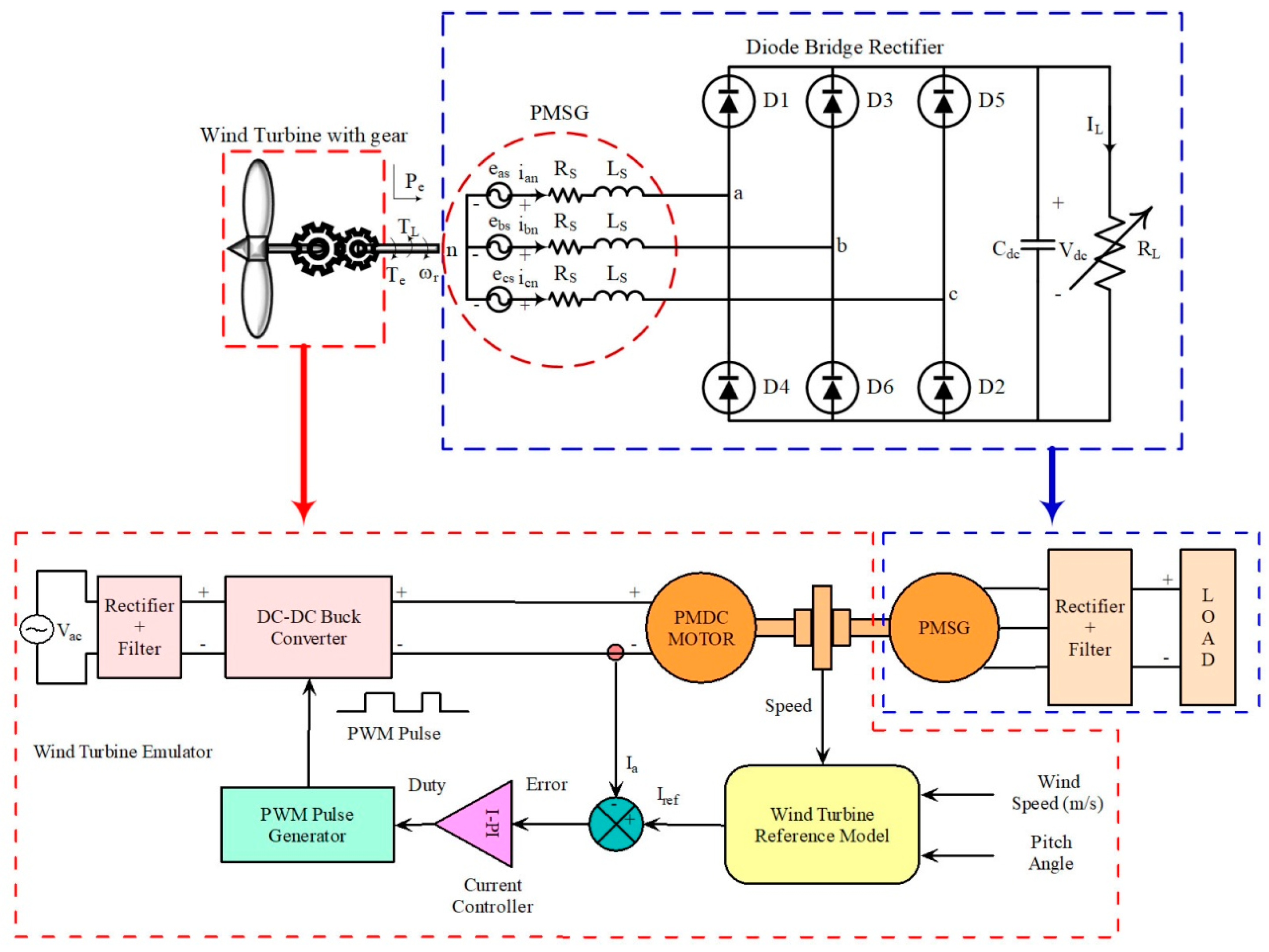
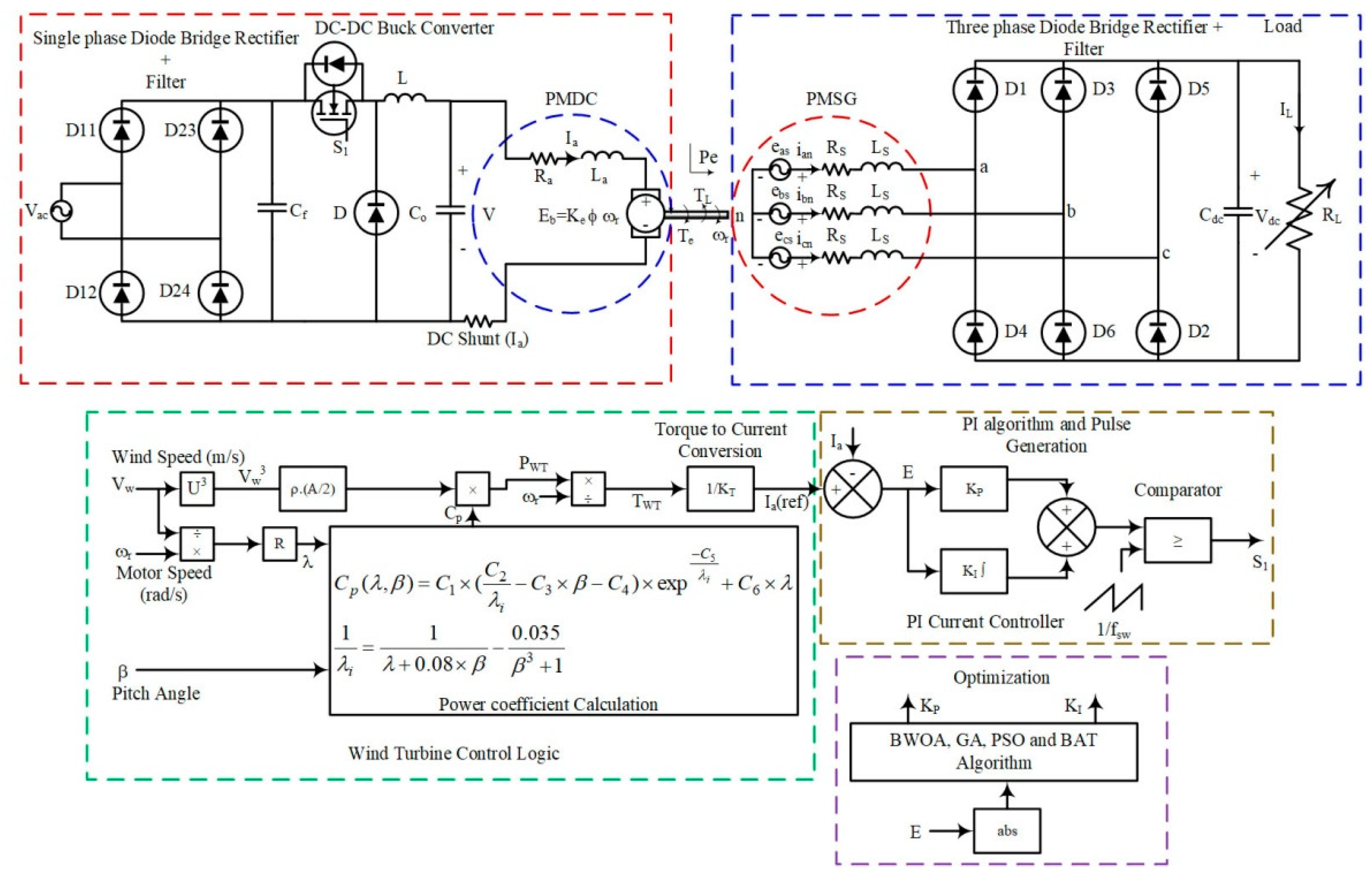
Figure 1 depicts the arrangement of the typical WT emulator. The WT emulator comprises of DC supply, DC–DC buck converter, PMDC motor, WT reference model, permanent magnet synchronous generator (PMSG), current controller, PWM pulse generator, and electrical load.
The WT reference model receives three inputs, i.e., wind speed, pitch angle, and speed of the PMDC motor. Based on these inputs, the WT model generates the reference current for the next stage. The reference current from the WT reference model and the armature current of the PMDC motor are compared, and it is processed through a proportional-integral current controller. The PI current controller generates the duty cycle for the next stage based on the error current. The duty cycle is processed through a PWM pulse generator to generate the PWM pulse for the DC–DC buck converter switch. The converter voltage and current vary based on the duty cycle, and it is used to control the PMDC motor characteristics. The PMDC motor emulates the WT reference model characteristics. In this WT emulator control structure, the PI controller parameters, such as proportional (KP) and integral (KI) gains, are optimized using a black widow optimization algorithm.
2.1. Modeling of WT Reference Model
The mathematical model of WT is the heart of the WT emulator. The WT’s mathematical model provides the reference torque or current for the current controller to mimic the characteristics of the WT using a DC–DC buck converter fed PMDC motor. The WT torque is related to the speed of the PMDC motor, pitch angle, and wind velocity, and it is expressed in Equation (1):
where
Cp(
λ,
β) is WT power coefficient,
VW is the wind velocity or speed (m/s),
R is the turbine radius (m),
ρ is the air density (kg/m
3),
β is the pitch angle (deg), and
λ is the tip speed ratio. The WT power coefficient is related to pitch angle and tip speed ratio, and it is expressed in Equation (2):
where
C1,
C2,
C3,
C4,
C5, and
C6 are the empirical power coefficients, and the values for these coefficients are 0.5176, 116, 0.4, 5, 21, and 0.0068, respectively.
λi is the tip speed ratio at
ith step time.
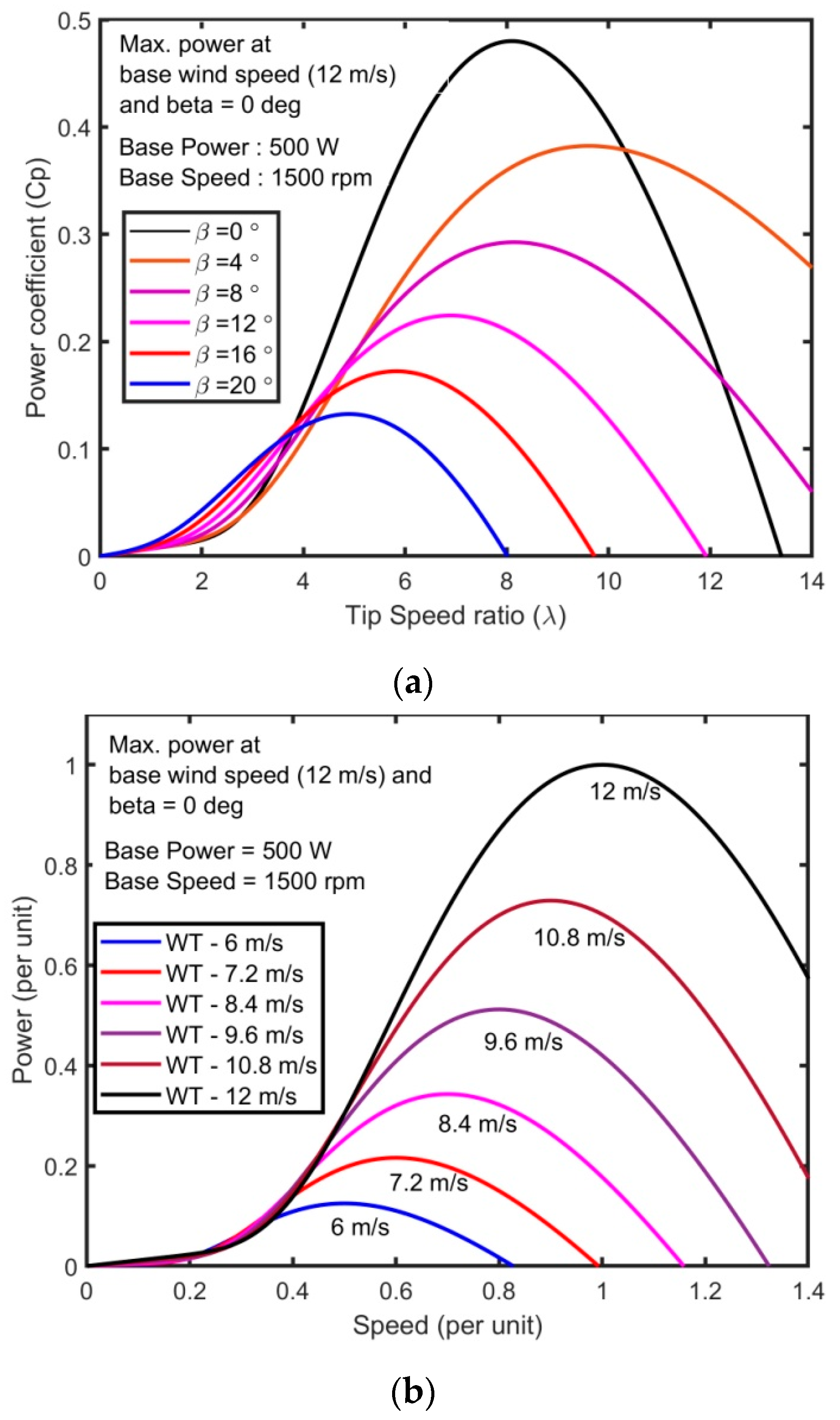
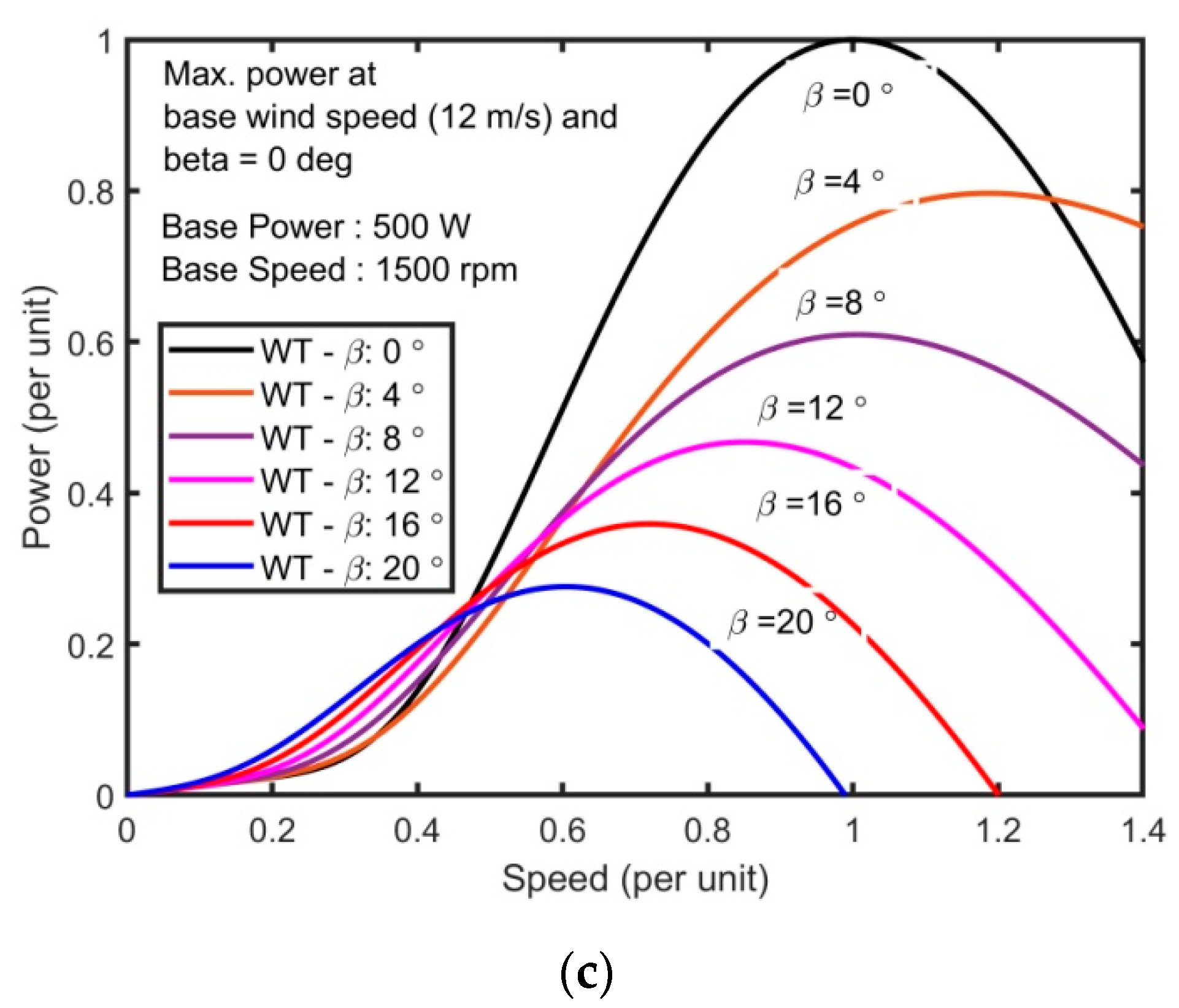
Figure 2a shows the WT power coefficient’s response concerning tip speed with different pitch angles. From this figure, the maximum power coefficient
Cpmax is 0.48 for pitch angle equal to 0° and normalized tip speed ratio (
λnom) equal to 8.1 [
23].
The tip speed ratio and power of the WT model being expressed in Equations (3) and (4), respectively,
where
A is the turbine swept area (m
2), and
N is the speed of the generator (rad/s). In this work, the rated power of the WT is fixed at 500 W; base wind speed is set at 12 m/s.
Figure 2b shows the response of WT power concerning the speed of the WT at different wind speed profiles, and
Figure 2c shows the response of WT power concerning the speed of the WT at different pitch angles.
2.2. Modeling of the DC–DC Buck Converter
The buck converter can convert the fixed DC voltage into a variable DC output voltage based on the buck converter’s duty cycle. The relation between duty cycle and an output voltage of the buck converter can be expressed as [
12]:
where
V(
s) is the converters output voltage, vs. is the input voltage,
D(
s) is the duty cycle, and
RL is a resistive load of the converter in ohms. The specification of parameters used for the DC–DC buck converter is: inductance (
L) is 10 mH, capacitance (
C) is 4800 μF, switching frequency is 3 kHz, the voltage rating is 240 V, and the power rating is 750 W.
2.3. Modeling of the PMDC Motor
The PMDC motor is used to convert electrical energy into useful mechanical energy based on its input voltage. The transfer functions related to the mechanical and electrical parameters of the motor, such as speed, input voltage, and armature current can be expressed as [
12]:
where
V(
s) is the input voltage of the motor,
Ia(
s) is the armature current of the motor,
N(
s) is the speed of the motor,
B is the frictional coefficient of the motor,
J is the inertia of the motor,
La is the armature inductance of the motor,
Ra is the armature resistance of the motor,
Kt is the torque constant of the motor and
Kb is the back emf constant of the motor. The specification used for this motor is:
J is 0.02215 kg-m
2,
B is 0.002953 N-m/(rad/s),
Ra is 2.581 ohms,
La is 0.028 H,
Kb is 0.08 V/rpm,
Kt is 1 N-m/A, the power rating is 700 W, and voltage rating is 220 V.
2.4. Modeling of the PI Controller
The transfer function model of the proportional-integral controller used for the WT emulator can be expressed as:
where
KP,
KI is proportional gain and integral gain of the PI controller, respectively. The error current is denoted by Δ
Ia(
s). Generally, the PI controller’s gain parameter is tuned by the trial and error method and the ZN method. However, these methods had some disadvantages, such as the trial and error method, which takes more time to find the PI controller’s optimal value; the ZN method only provides the initial guess for the PI controller’s gain parameter. To overcome this problem, optimization techniques may be utilized to adjust the parameter of the PI controller. In this work, a new optimization algorithm, i.e., a black widow optimization algorithm, is used to optimize the parameter of the PI current controller of the emulator to emulate the exact characteristics of the reference WT mathematical model.
Figure 3 shows the overall block diagram of the PI controlled DC–DC converter fed PMDC motor-based WT emulator.
3. Tuning of PI Current Controller of WT Emulator Using BWOA
The proposed near accurate WT emulator using a black widow optimization algorithm optimized PI controlled DC–DC converter fed permanent magnet direct current (PMDC) motor is presented in this section. The PI current controller parameters such as proportional gain (
KP) and integral gain (
KI) of the WT emulator is optimized using the black widow optimization algorithm (BWOA). The black widow optimization algorithm is imitating the lifestyle of the evolution of the black widow spider. Generally, female black widow spiders make the net during the night and leave some pheromone in some place of her net to attract male black spiders to have matting. Male black widow spiders get attracted by this pheromone and join in the net. The female black widow spider eats the male black widow spider after or during mating. After mating, the female black widow lays egg socks on the net. After 11 days, young spiders come out from the eggs, and these spiders will participate in sibling cannibalism. The young spiders stay in the mother’s net for a short period, and interestingly, the mother even eats some young spiders during this brief period sometimes. Other young spiders from the net are considered the fittest young spiders based on this concept; this black widow optimization algorithm is developed [
24].
The black widow optimization proceeds with a random initial black widow spider population. This population has male and female black widow spiders for generating offspring for the next generation. The initial population of black widow spiders can be expressed as
where
XN,d is the population of black widow spiders,
d is the number of decision variables,
N is the number of population,
lb is the lower bound of the population, and
ub is the upper bound of the population. The potential solution populations (
XN,d) are used to minimize or maximize the following objective function represented in Equation (12):
The next process in the black widow optimization algorithm is reproducing the young spiders from male and female spiders’ mating. During or after mating, male spiders may be eaten by female spiders. The random selection process is used to select the pair of spiders for mating to reproduce young spiders. The reproduction process of the black widow optimization is expressed by the equation given in Equation (13):
where
Yi,d, and
Yj,d are the young spiders from reproduction,
i and
j are a random number between 1 to
N and
β is the random number between 0 to 1. To avoid random duplication selection of pairs, the reproduction process is carried out for
d/2 times.
After reproduction, the mother spider population and young spider population are sorted with their fitness function value and cannibalism rate. During the optimization process, three cannibalism procedures are considered. The first one is sexual cannibalism, where the female spider population eats the male spider population during or after mating. This concept can be applied to the fitness value of the female and male spider populations. The second one is sibling cannibalism, where the healthy young spiders eat the weaker young spiders. This concept is applied using cannibalism rate, and with this rate only, fittest young spiders remain in the population, and others are discarded from the population. In the third type of cannibalism, the young spiders eat their mother. This concept is applied based on the fitness value of the mother spider and young spiders.
The next process in the black widow optimization is mutation. The young spiders are selected based on the mutation rate, and a small random value is added with selected young spiders for mutation; and this process is expressed in Equation (14):
where
Zk,d is the mutated spider population,
Yk,d is the randomly selected young spider,
k is the random number, and
α is the random mutate value.
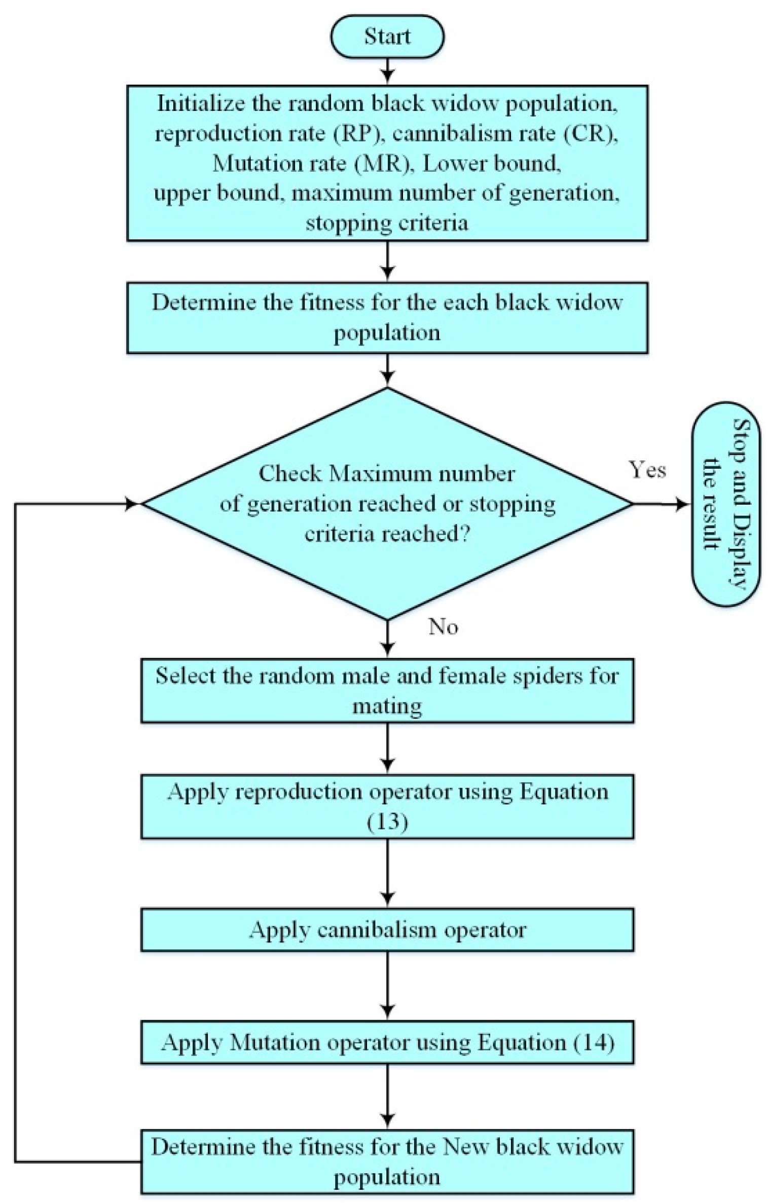
This black widow optimization algorithm depends on three parameters, namely the reproduction rate (RP), cannibalism rate (CP), and mutation rate (MR). The reproduction rate controls the generation of young spiders and provides opportunities to explore the search space for finding a better solution. The cannibalism rate controls the weaker fittest population in the generation, and only the stronger fittest populations are allowed for the next generation. The mutation rate controls the diversity in the current generation to the next generation. The flowchart for the BWOA is shown in
Figure 4.
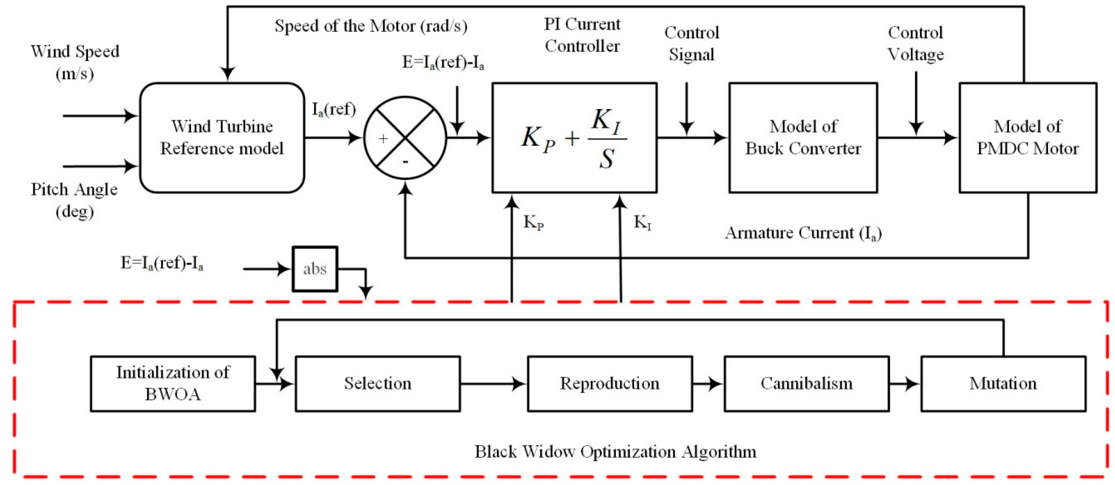
The optimization of the PI controller using BWOA is shown in
Figure 5. The BWOA receives the absolute current error as a fitness value from the WT emulator. BWOA optimizes the proportional gain and integral gain to minimize the absolute error in the system. To verify the black window optimization method’s effectiveness, it is compared with the BAT algorithm, particle swarm optimization, and genetic algorithm. The parameter used for the GA, PSO, and BWOA is shown in
Table 1.
The GA, PSO, BAT, and BWOA optimization is implemented in the R2017b MATLAB software and tested in an i3-4005U CPU, 1.7 GHz personal computer. These algorithms have been executed for 100 runs and 4040 fitness value evaluated in a single run, i.e., 40 population with 100 generation, which equals 4000 fitness value evaluation plus fitness value evaluation for an initial 40 random population. Optimization algorithm results such as optimal gain parameter, best fitness, worst fitness, standard deviation, mean fitness value, and average computation time are taken for 100 trials with GA, PSO, BAT, and BWOA are presented in
Table 2. The convergence plots for these algorithms are provided in
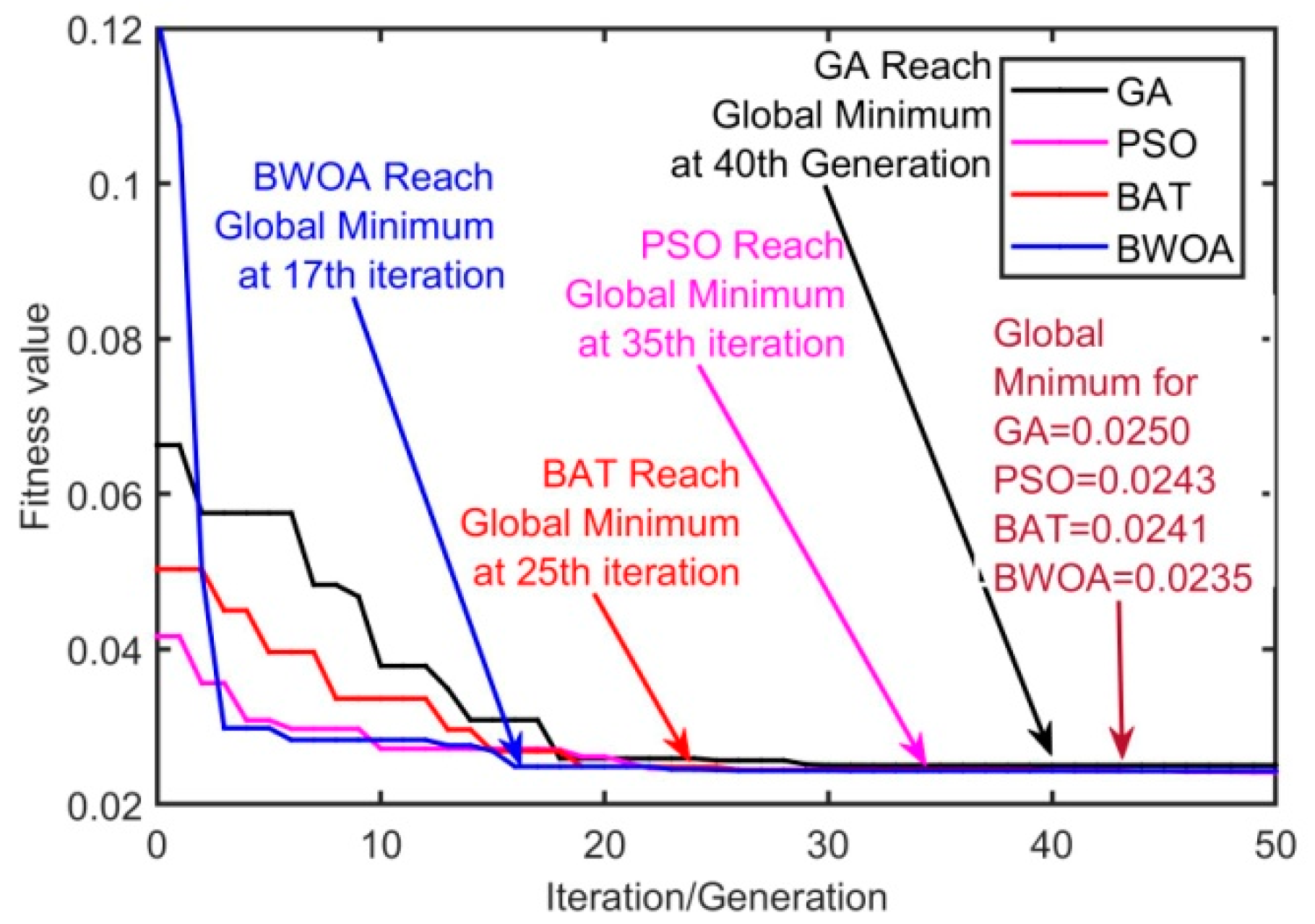
Figure 6.
From the test results, GA has a fitness value of 0.025 and computation time of 339 s, PSO has a fitness value of 0.0243 and computation time of 371 s, BAT algorithm has a fitness value of 0.0241 and computation time of 439 s, but BWOA has best less fitness value of 0.0235 and less computation time of 332 s when compared with algorithms mentioned above. From the convergence plot, it is clear that GA takes 40 generations to reach the global minimum value of 0.025, PSO takes 35 generations to reach a global minimum value of 0.0243, BAT algorithm takes 25 generations to reach a global minimum value of 0.0241, but BWOA takes only 17 generations to reach the global minimum value of 0.0235. Thus black widow optimization algorithm has outperformed the other considered GA, PSO, and BAT algorithms and exhibited better performance.
4. Simulation Results and Discussions
In this section, the simulation result of GA, PSO, BAT, and BWOA algorithm optimized PI controlled DC–DC buck converter fed PMDC motor based WT emulator is tested with different operating conditions such as WT emulator power-speed characteristics for static wind profile settings, WT emulator power-speed characteristics for static pitch angle settings, step-change in wind profile settings and step-change pitch angle settings.
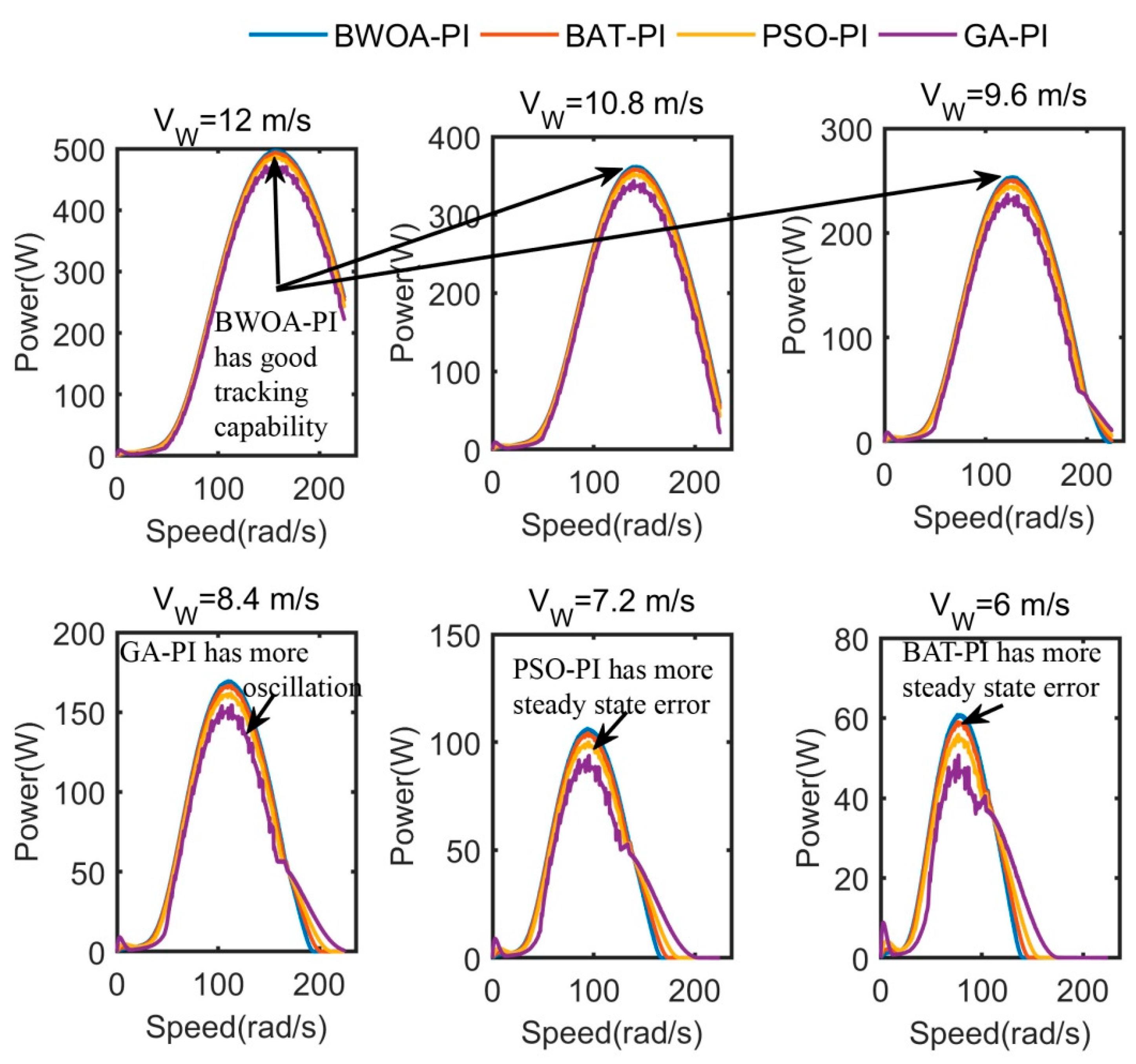
Wind speed profile set at 12 m/s, 10.8 m/s, 9.6 m/s, 8.4 m/s, 7.2 m/s, and 6 m/s in wind reference models with a pitch angle maintained at 0°. The corresponding WT emulator power is measured for different speeds of the WT emulator.
Figure 7 shows the WT emulator power response with respect speed of the emulator at different wind speed profile settings with GA-PI, PSO-PI, BAT-PI, and BWOA-PI controlled WT emulator.
The emulation efficiency of the WT emulator is related to the power of the wind turbine emulator (
PWTE) and power of the wind turbine reference model (
PWTR), and it is expressed in Equation (15):
Table 3 shows the emulation efficiency of the WT emulator for different wind speed profiles. The WT emulator’s emulation efficiency range with the GA-PI controller is from 81% to 95.42%, from 88.31% to 97.34% with PSO-PI controller, from 94.85% to 98.21% with BAT-PI controller, and for BWOA-PI controller, it is from 97.63% to 99.32%. It is evident that BWOA-PI controlled WT emulator has provided maximum efficiency than GA, PSO, and BAT PI-controlled WT emulator.
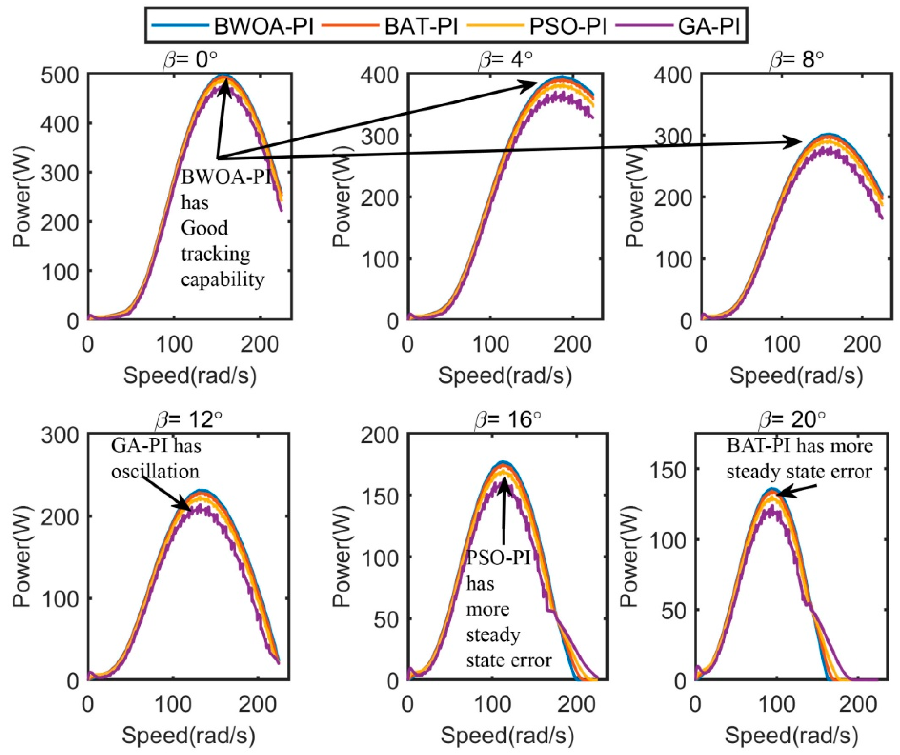
Pitch angle is set at 0°, 4°, 8°, 12°, 16° and 20° in wind reference model (wind speed fixed at 12 m/s), and corresponding WT emulator power is measured for different speeds of the WT emulator.
Figure 8 shows the WT emulator power-speed characteristics for different pitch angle settings with GA-PI, PSO-PI, BAT-PI, and BWOA-PI controlled WT emulator. The emulation efficiency of the WT emulator is calculated using Equation (15), and the corresponding details are provided in
Table 4.
The emulation efficiency range of the WT emulator with the GA-PI controller is from 89.2% to 95.4%, from 93.7% to 97.08% with the PSO-PI controller, from 96.74% to 98.44% with BAT-PI controller, and for BWOA-PI controller, it is from 98.48% to 99.36%. It is ascertained that BWOA-PI controlled WT emulator has provided maximum efficiency than GA, PSO, and BAT PI-controlled WT emulator.
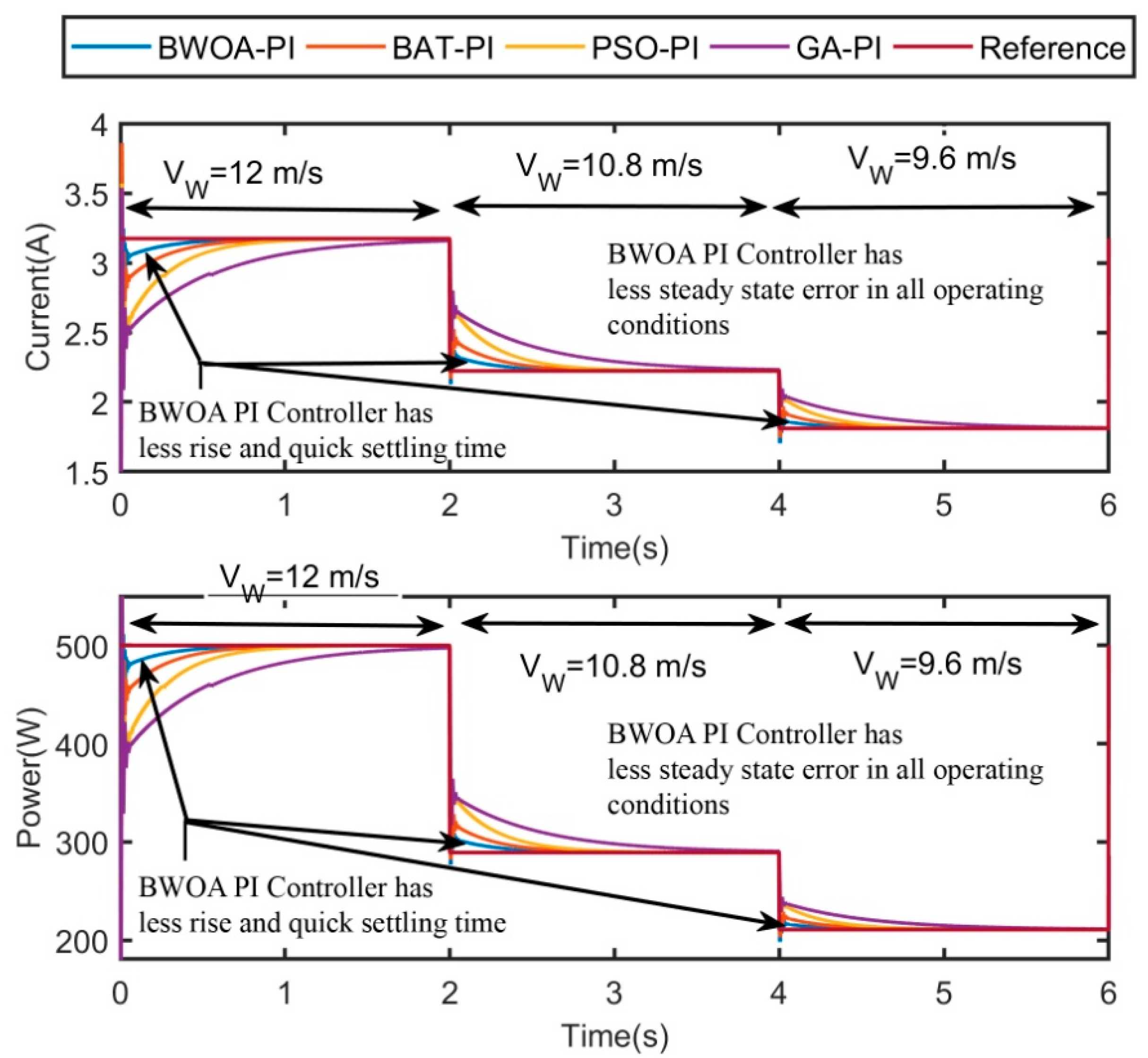
WT emulator is tested for a step-change in wind speed profile, i.e., wind speed is varied from 12 m/s to 10.8 m/s, 10.8 m/s to 9.6 m/s for every 2 s, and corresponding results are measured. The WT emulator’s current and power response with GA, PSO, BAT, and BWOA optimized PI controller is shown in
Figure 9, and the corresponding performance results are presented in
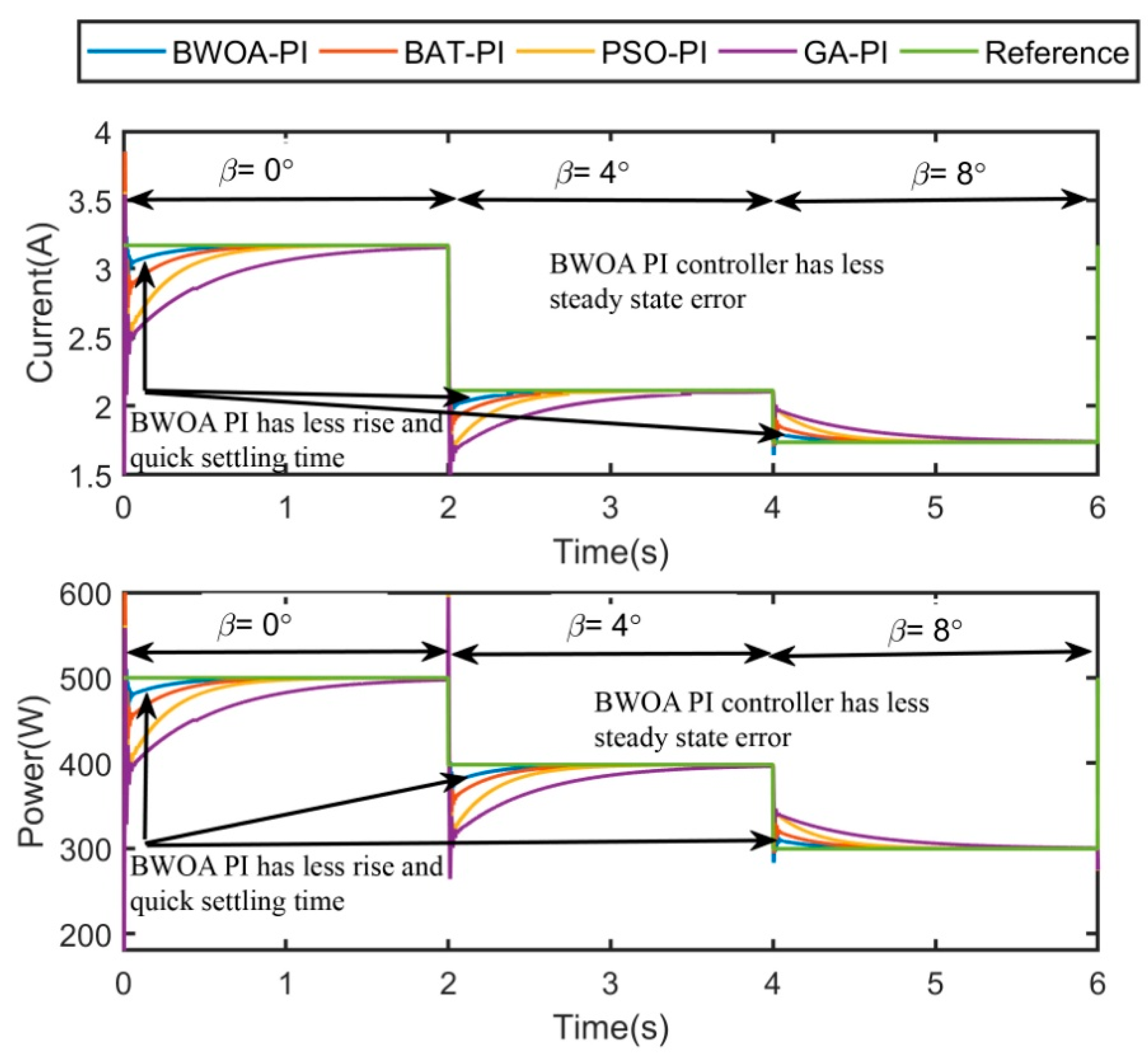
Table 5. From this result, the BWOA PI-controlled WT emulator has a less steady-state error, quick settling time, and less rise time. These parameters are not in favor of the other considered algorithms such as GA, PSO, and BAT algorithm optimized PI controlled WT emulator. WT emulator is tested for a step-change in pitch angle, i.e., the pitch angle is varied from 0° to 4°, 4° to 8° for every 2 s, and corresponding results are measured. The WT emulator’s current and power response with GA, PSO, BAT, and BWOA optimized PI controller is shown in
Figure 10, and corresponding performance results are presented in
Table 6.
From these results, it is observed that the BWOA PI-controlled WT emulator has a less steady-state error, quick settling time, and less rise time. However, these parameters are not in favor of the other considered algorithms such as GA, PSO, and BAT algorithm optimized PI controlled WT emulator. A black widow optimization algorithm optimized PI controlled WT emulator has shown better performance in all operating conditions from these results analyses. In the next section, BWOA optimized PI controlled WT emulator is tested experimentally.
5. Experimental Verification of BWOA Optimized PI Controlled WT Emulator
In this section, experimental verification of the BWOA algorithm optimized PI controlled WT emulator is presented.
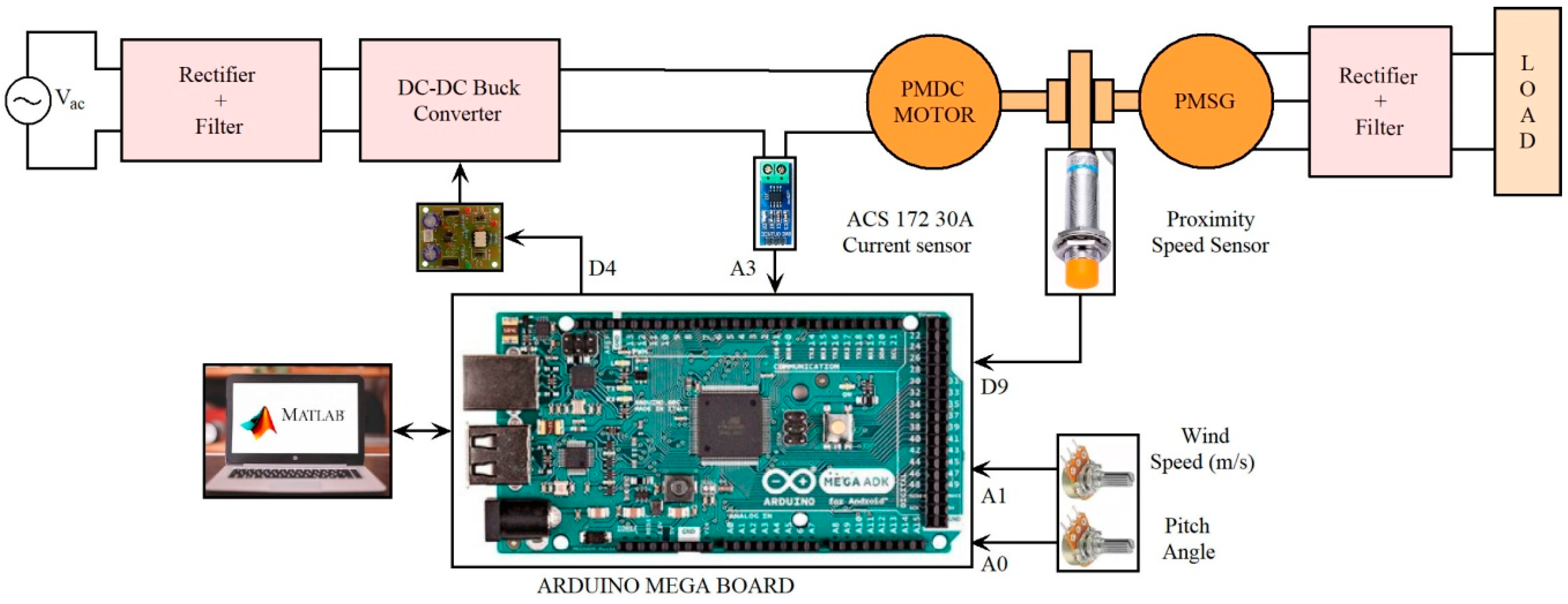
Figure 11 shows the hardware block diagram of the proposed WT emulator.
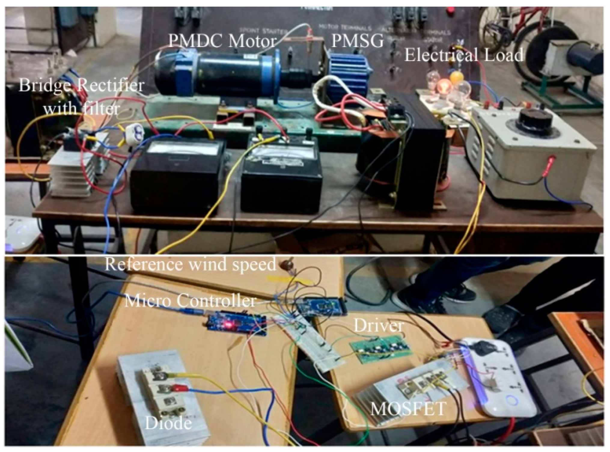
Figure 12 shows the snapshot of the hardware setup of the proposed WT emulator.
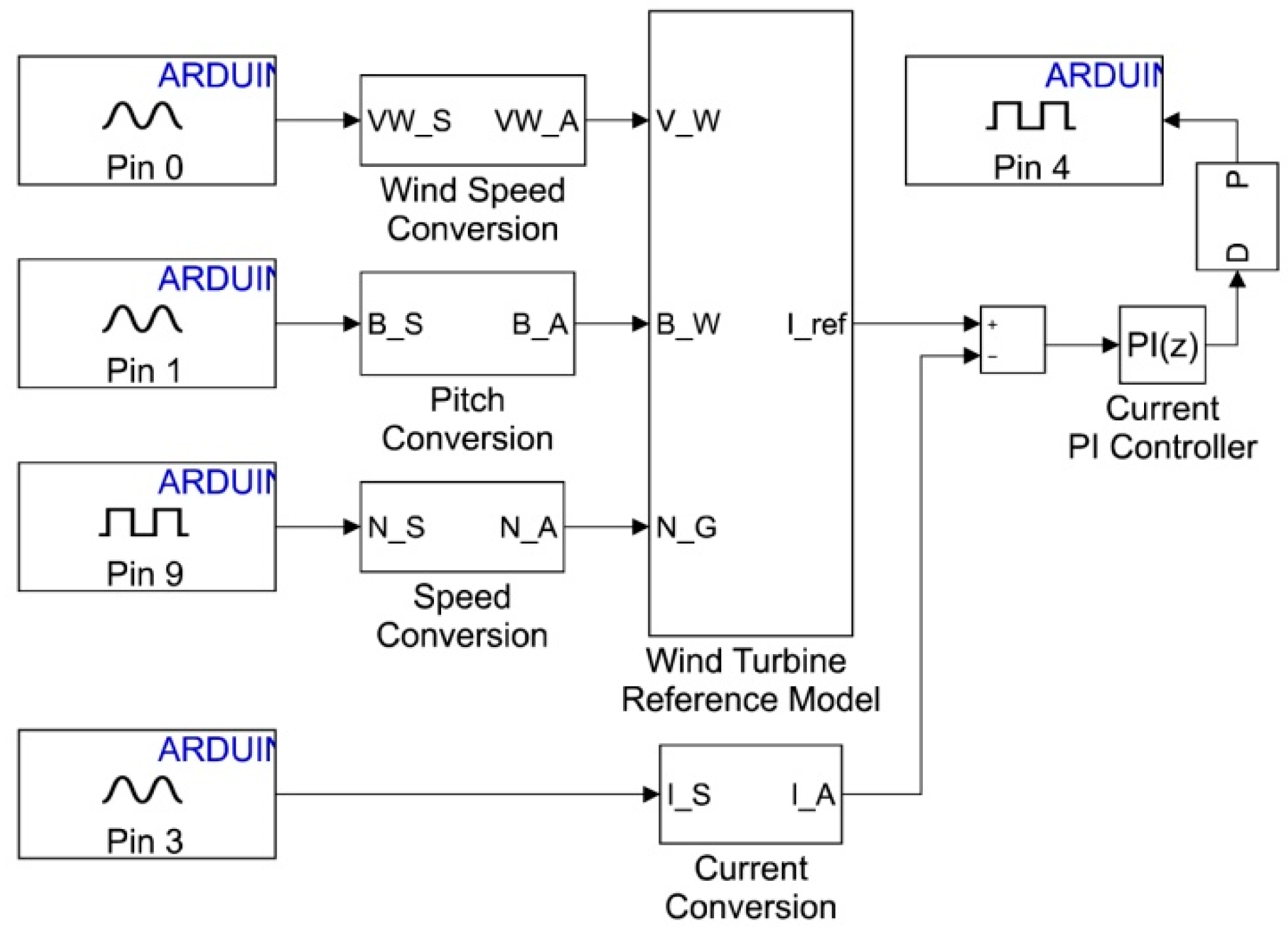
Figure 13 shows the control logic implemented in the ARDUNIO mega board using the MATLAB/Simulink environment.
A total of two potentiometers are used for providing wind speed and pitch angle command for the WT reference model. The proximity sensor used for sensing the PMDC motor’s speed is the third input for the WT reference model. ACS 172-30A is used for measuring the current of the PMDC motor. The wind speed command, pitch angle command, and current sensor data being received in the analog channel (A0, A1, and A3 pins) of the ARDUINO mega board. The proximity sensor data are received in the ARDUINO mega board in the digital pin (D9 pin). The wind speed command, pitch angle command, current sensor data, and speed sensor data are converted into a suitable form using conversion blocks. After conversion, these data are processed via the WT reference model and PI controller to generate the corresponding duty cycle. This duty cycle is processed via the PWM generating unit to generate the DC–DC buck converter’s MOSFET pulse. The generated pulse is taken out from the digital pin (D4 pin) of the ARDUINO mega board and given through the driver board to control the buck converter for emulating the characteristics of the WT reference model.
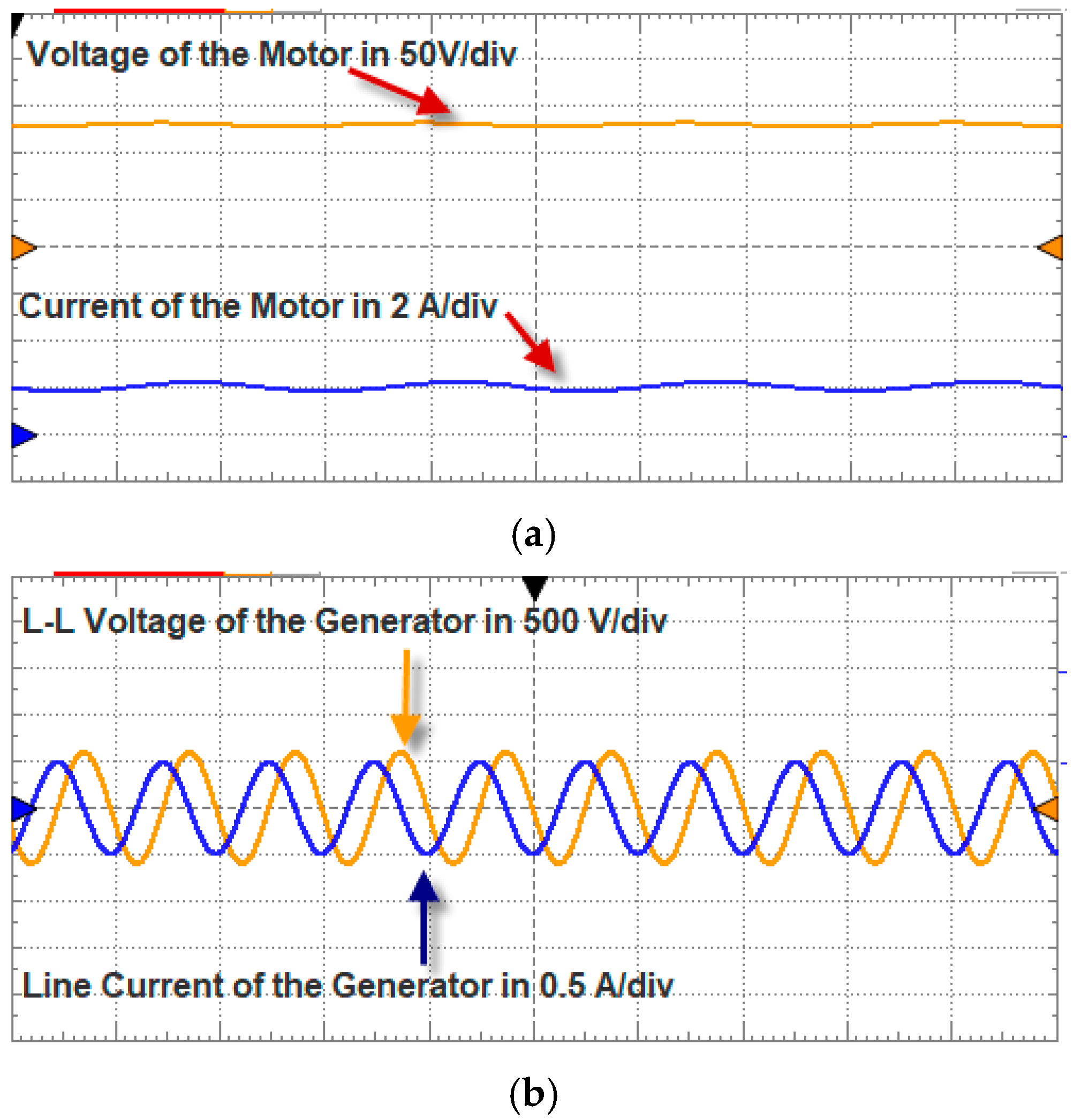
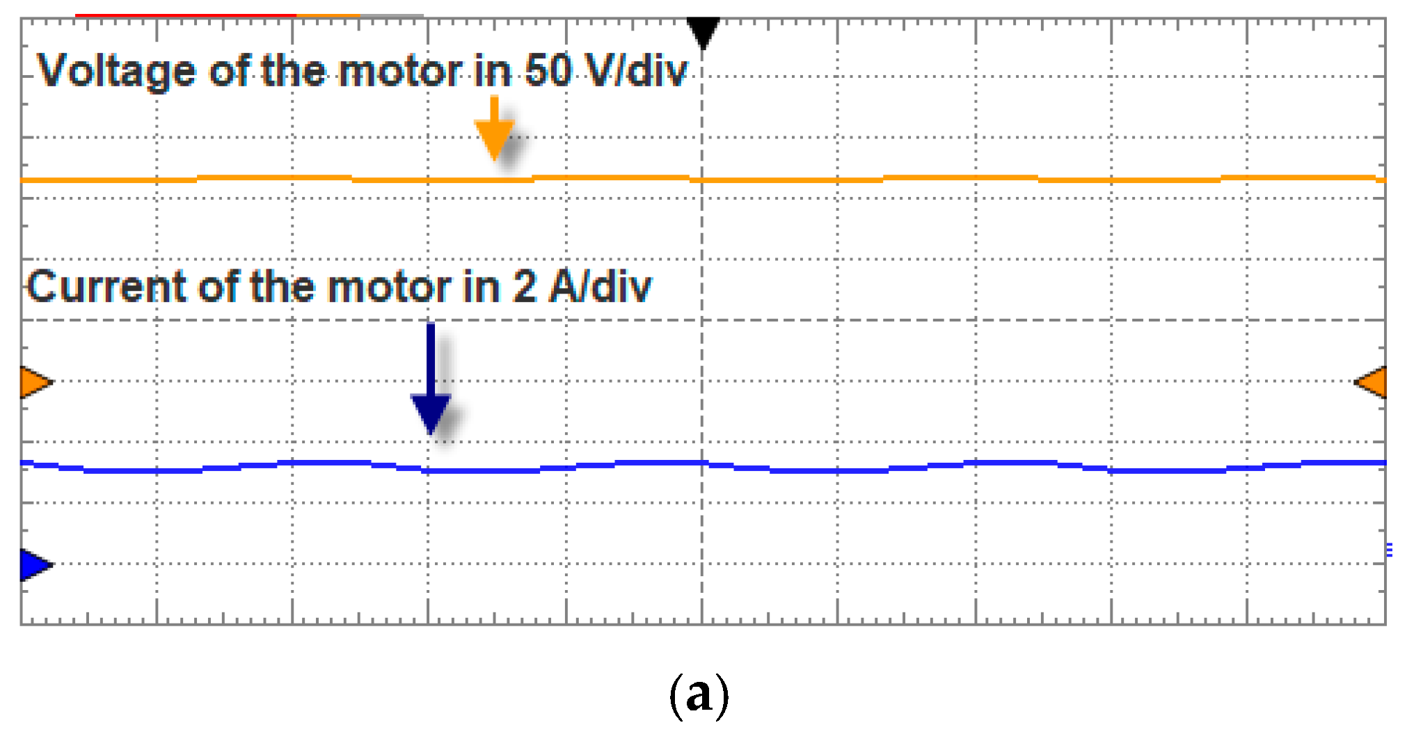
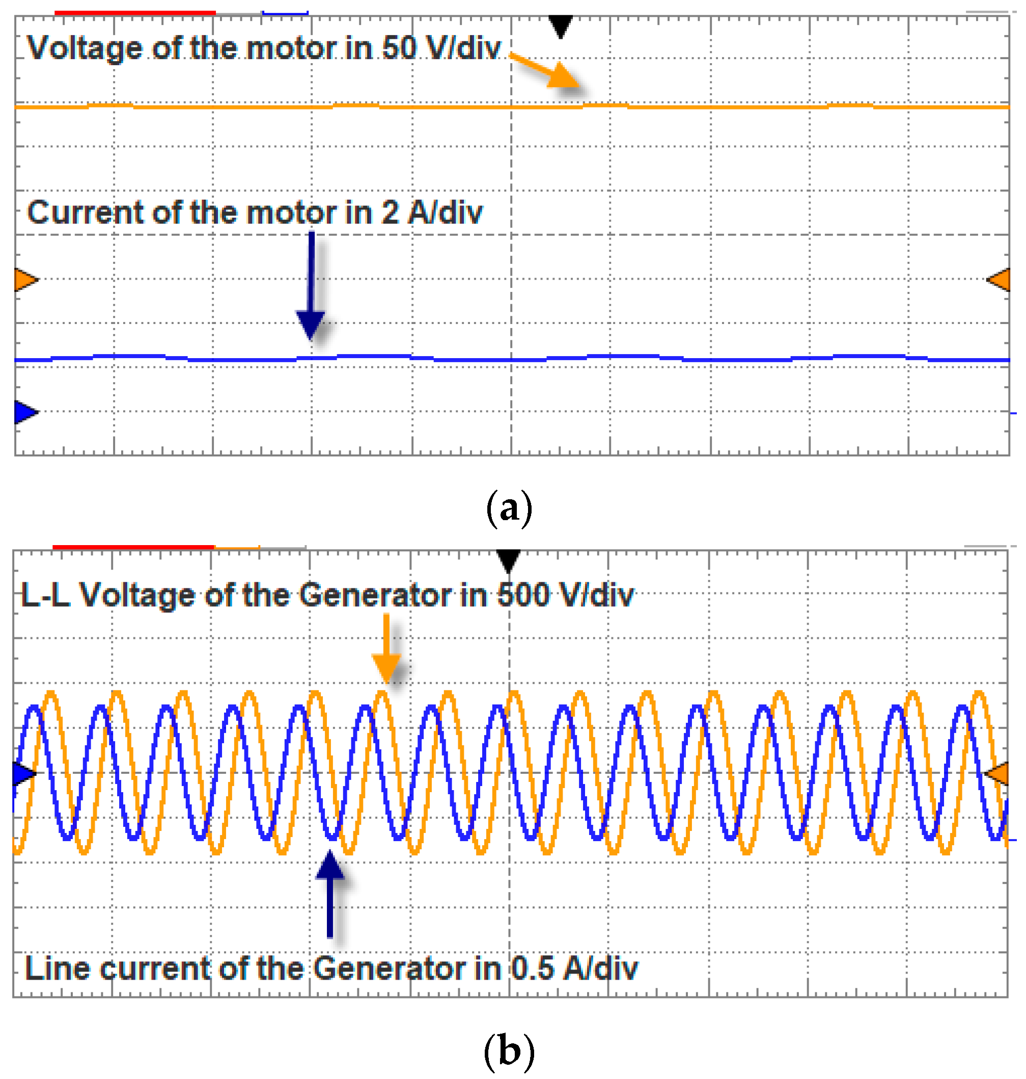
Three operating conditions are considered for testing the effectiveness of the BWOA optimized PI controlled WT emulator in real-time. In case 1, Wind speed is set at 9.6 m/s. Pitch angle is set at 0° using potentiometer of the hardware setup and corresponding results such as the voltage of the motor, current of the motor, the line to line voltage of the generator and line current of the generator are measured and shown in
Figure 14. The motor’s voltage is around 135 V, the current of the motor is around 2 A, and the motor’s power is 270 W. The emulation efficiency obtained from the hardware is around 97.5%, and for simulation, it is around 98.95%. In case 2, Wind speed is set at 12 m/s. Pitch angle is set at 0° using potentiometer of the hardware setup and corresponding results such as the voltage of the motor, current of the motor, the line to line voltage of the generator and line current of the generator are measured and shown in
Figure 15. The motor’s voltage is around 163 V, the current of the motor is around 3 A, and the power consumed by the motor is 480 W. The emulation efficiency obtained from hardware is around 97.8%, and it is 99.36% for the simulation analysis.
In case 3, Wind speed is set at 12 m/s, and the pitch angle is set at 4° using potentiometer of the hardware setup. The corresponding results, such as voltage and current of the motor, line-to-line voltage of the generator, and line current of the generator, are measured and shown in
Figure 16. The motor’s voltage is around 204 V, the current of the motor is around 2.4 A, and the motor’s power is 489.6 W. The emulation efficiency obtained from the hardware is around 97.92%, and for simulation, it is around 99.05%. Comparisons of the emulation efficiency from simulation and experimentation for the three cases are shown in
Table 7. From the results, it is observed that experimentation results deviate minimally from the simulation results.

 ,
, 


