Article

Numerical Simulation of the Interaction between Fibre Concrete Slab and Subsoil—The Impact of Selected Determining Factors

Department of Geotechnics and Underground Engineering, Faculty of Civil Engineering, VSB-Technical University of Ostrava, 708 00 Ostrava-Poruba, Czech Republic
*
Author to whom correspondence should be addressed.
Sustainability 2020, 12(23), 10036; https://doi.org/10.3390/su122310036
Submission received: 11 November 2020 / Revised: 20 November 2020 / Accepted: 23 November 2020 / Published: 1 December 2020
(This article belongs to the Special Issue Civil Engineering as a Tool for Developing a Sustainable Society)

Abstract

:
Shape and material optimization of building structures, including reducing the amount of concrete used, are very important aspects in sustainable construction. Numerical modelling is currently used very effectively to design optimized and sustainable structures, including their interaction with the surrounding rock environment. This paper is focused on the three selected factors of numerical modelling of fibre concrete slab and subsoil interaction: (1) the constitutive model of fibre concrete slab, (2) deformational and strength characteristics of subsoil, (3) effect of interface elements. The specialized geotechnical software Midas GTS NX, based on the finite element method, was used for the modelling of this task. Numerical results were compared with the experimental measurement of vertical displacements on the upper surface of slab. In the presented study, three constitutive models of slab recommended in MIDAS GTS NX code for modelling concrete behaviour (elastic, Mohr-Coulomb and Drucker-Prager) were applied. In addition, the sensitivity analysis with respect to the deformational and strength characteristics of subsoil was performed. The numerical study also presents the effect of the interface elements application on the slab behaviour. The numerical results of maximum vertical displacements based on the Drucker-Prager and elastic model underestimated both the experimental results and numerical results based on the Mohr-Coulomb model. From the qualitative point of view (shape of deflection curve), the numerical simulation showed the better agreement of the Mohr-Coulomb constitutive model with the experimental measurements in comparison with the other two investigated constitutive models. The performed parametric study documented that reduction of the strength and deformational characteristics of subsoil leads to the increase of maximum vertical displacements in the centre of slab, but the experimentally measured deflection curve, including uplift of slab and gapping occurrence between the slab and subsoil, was not achieved without the interface application.

1. Introduction

Sustainable civil engineering belongs to the crucial area of the sustainable society development. It presupposes the development, research and practical application of new technologies and building materials and optimization of design and construction work. Although building materials are permeably innovated, concrete remains one of the most widely used materials in building construction process. In the context of sustainable construction, significant attention is focused on the use of various types of modified concrete with improved properties, which can significantly contribute to reducing the amount of concrete required to ensure reliability and durability of buildings.
One way to improve the characteristics of concrete, especially the tensile strength, post-peak behaviour, ductility and energy-dissipation ability, is to add fibres (dispersed reinforcement) of different materials (steel, polypropylene etc.), of different character and size, to the concrete mixture [1,2,3,4]. Fibre concrete is increasingly used in foundation structures or industrial floors also [5,6]. Fundamental advantages of steel fibre concrete structure investigated in the presented study can be summarized [7,8,9]:
  • the increased load-bearing capacity of concrete structure
  • reduction of concrete slab thickness
  • increased durability
  • low maintenance costs
  • improved flexural properties
  • reduced site work for managing steel reinforcement
  • reduced project costs
  • increased impact and abrasion resistance
Character of soil—structure interaction is depended not only on the structures itself, but the subsoil must be considered also. For example, the different behaviour of an identical foundation structure, interacting with the different character of the subsoil, is documented in [10,11].
Many research studies around the world are devoted to the topic of the interaction of structures with the subsoil [12,13,14,15,16,17,18,19,20,21,22,23,24].
This interaction can be studied by various methods—experimental or computational methods are usually used. This paper is mainly focused on the numerical simulation of the mentioned interaction and assessments of impact of the following determining factors: choice of constitutive model of fibre concrete slab, deformational and strength characteristics of subsoil, effect of interface elements.
Approaches to the modelling of the structure—subsoil interaction are characterized by different degrees of simplification of this real, complex, generally non-linear contact problem [25,26,27,28,29,30,31,32,33,34]. The usual approach in the structural engineering is often focused on the most detailed modelling of the foundation structure itself [35] and the subsoil is often simplified by spring models (Winkler, Pasternak, etc.) [36,37]. But these spring approaches cannot express very complicated, multiphase, non-linear behaviour of soil material, especially in case of a occurrence of more significant plastic deformation in subsoil.
On the other hand, the specialized geotechnical software (PLAXIS, MIDAS GTS, UDEC etc.) to the modelling of this interaction deal in more detail with the real subsoil behaviour and the foundation structure is often simplified only (only the elastic behaviour of foundation is very often assumed) [38,39].
None of these above-mentioned approaches can fully cover all aspects of this interaction. In the real problems, the behaviour of both construction materials and subsoil is complicated, non-linear, it cannot be simply described by an elastic constitutive model and utilization of elastoplastic constitutive models is needed.
The finite element method is widely used numerical method in the engineering, including in the geotechnical engineering, it allows consider the significant material and geometric variability of the problem and complex behaviour of material. In this context, however, it should be emphasized that finite element method is a method of continuum modelling, thus the continuous deformation between the finite elements is generally assumed. The modelling of initiation and development of cracks, separation and detachment of certain parts of the model can be done in a simplified way only, for example by introducing a suitable constitutive model, by introducing contact (interface) elements, etc.
This paper presents the numerical modelling of fibre concrete slab—subsoil interaction assuming the application of three various constitutive models for concrete slab recommended by MIDAS GTS NX code for the modelling of concrete structures. In addition to basic linear elastic model, Mohr-Coulomb and Drucker-Prager models were applied and compared. It is known that many specialized advanced constitutive models are developed by many authors and they are used to the more realistic characterization of the concrete behaviour. But, the advanced constitutive models for concrete are usually not implemented in the commercial geotechnical software (PLAXIS, MIDAS GTS). These specialized geotechnical software packages simplify the behaviour of concrete and recommend the use of a linearly elastic, Mohr-Coulomb or Drucker-Prager model constitutive models for concrete behaviour simulation. Thus, this paper is mainly focused on the comparison of numerical results based on the previously mentioned constitutive models widely used in the specialized geotechnical software.
The paper presents also the influence of Young’s modulus, cohesion and friction angle of the subsoil and the application of contact (interface) elements between the slab and the subsoil on this interaction, both from a qualitative and a quantitative point of view.

2. Materials & Methods

In this paper, the specialized geotechnical software MIDAS GTS NX based on the finite element method was used to study the soil-structure interaction assuming (a) different constitutive models (elastic, Mohr-Coulomb, Drucker-Prager), (b) variant strength and deformational characteristics of subsoil and (c) the specific character of contact between the soil and structure. The presented numerical model was calibrated based on experimental measurements of vertical displacements measured on the upper surface of slab.

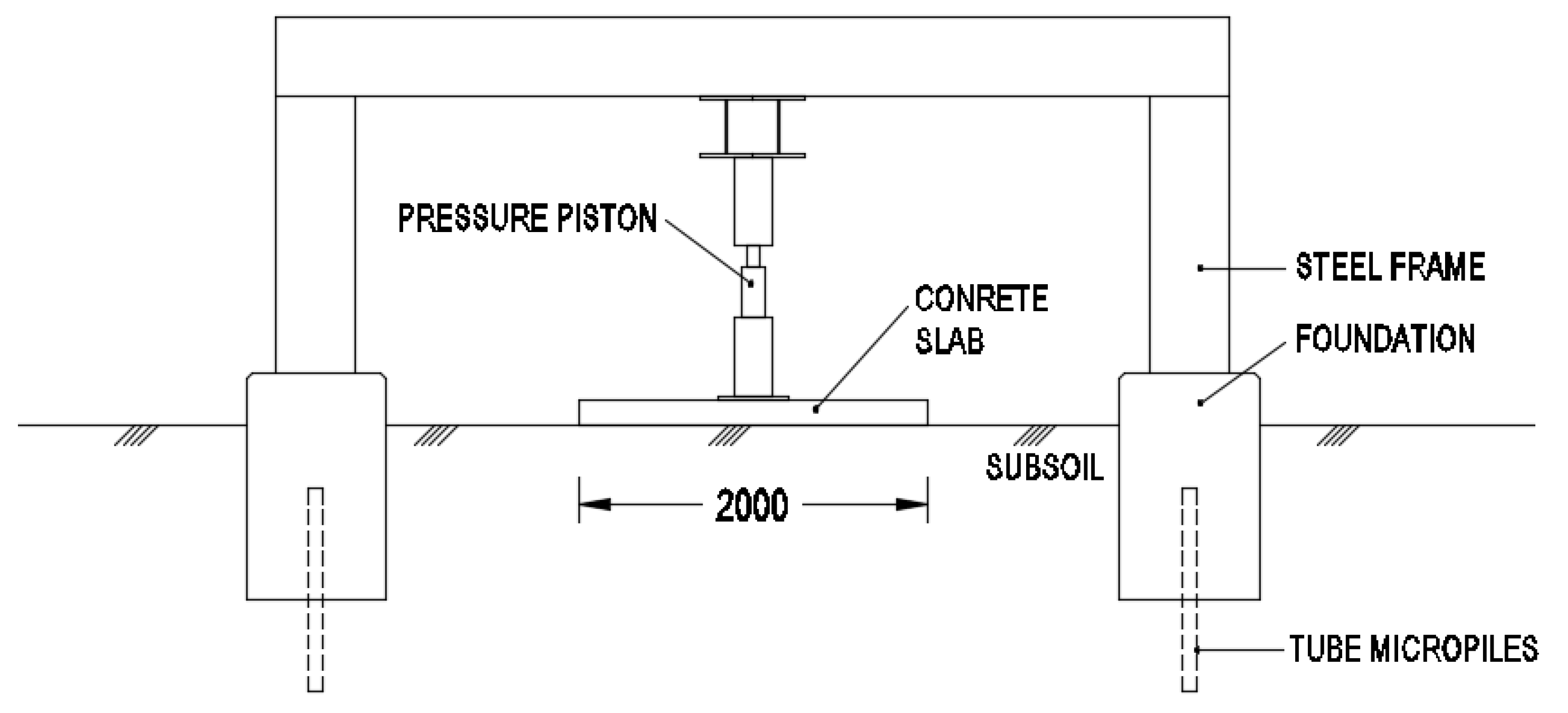
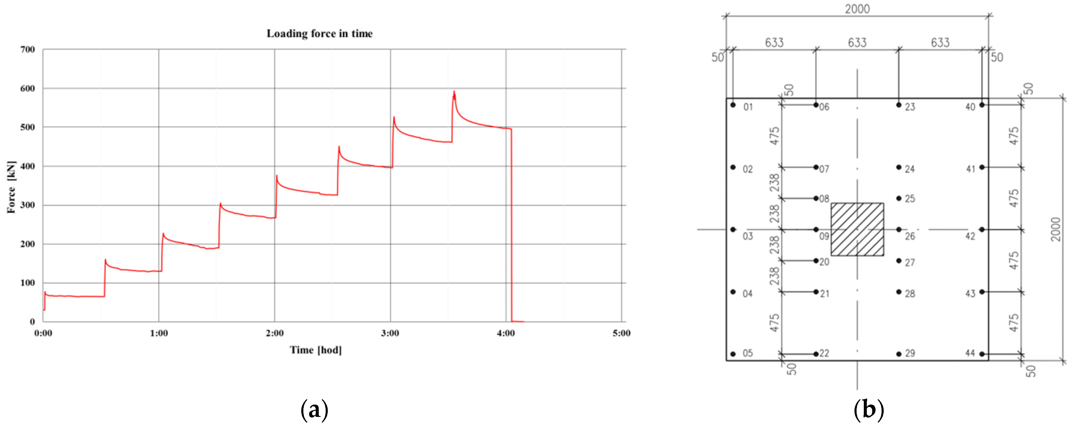
2.1. Fundamental Characteristics and Results of Experimental Fibre Concrete Slab Testing

The experiments were carried out on an experimental frame located at the Faculty of Civil Engineering, VSB-Technical University Ostrava [40]. The primary aim of the experiment was to determine the behaviour and the limit load-bearing capacity of slabs of different sizes and from different materials [41,42]. A slab with dimensions of 2 × 2 m and a thickness of 0.15 m was used to calibrate the numerical model. The slab was made from concrete C20/25 with dosage of 25 kg of steel DRAMIX 3D 65/60BG fibres (length 60 mm, diameter 0.9 mm) per cubic of concrete. This slab, exposed to a stepwise centric load, was tested. The external load was transferred to the tested slab using a steel distribution plate with dimensions of 0.4 × 0.4 m placed between the concrete slab and the load hydraulic press. The scheme of the load experiment is shown in the Figure 1.
The average cube strength of fibre concrete with dosage of 25 kg/m3 of added fibres was determined (in place drilled samples were laboratory tested) at 30.9 MPa (size of the samples 150 × 150 × 150 mm) and cylindrical strength at 24.86 MPa (sample diameter 150 mm, height 300 mm). The tensile strength of 2.48 MPa was assessed by calculation only as one tenth of cylindrical compressive strength of fibre concrete. The modulus of elasticity of fibre concrete material was assessed 19.7 GPa. All measured parameters of fibre concrete are listed in the Table 1 [41].
Due to the focus of the paper, we do not deal in this paper with uncertainties in the input characteristics of the fibre concrete material and the dispersion of fibres in the concrete mixture.
The slab was centrically loaded by means of a hydraulic press. A total of 8 load cycles according the stepwise load curve (Figure 2a) were performed until the complete failure (punching) of the slab was manifested. The maximum loading force at punching achieved 593 kN. The loading process was controlled, a total of 24 sensors with continuous recording of vertical displacements of the upper surface of slab were installed and evaluated during loading process (Figure 2b). The reference cross-section between the sensors No. 23 and No. 29, used to the comparison with the numerical model presented below, is highlighted by a dashed line in Figure 2b. This reference cross-section is situated as close as possible to the slab centre. The choice of this cross- section resulted from the maximum number of accessible fitted measuring sensors in this section.
The character of the subsoil under the investigated slab corresponded to sandy clay CS (with a minimum thickness of ten meters under the tested slab). The elastic modulus E of subsoil was assessed based on static load test, other soil characteristics were determined in the laboratory. Parameters of subsoil are given in the Table 2.
At specific load, the monitored vertical displacements documented the deflection of the slab, the lifting of it and corresponding gapping occurrence under the corners and edges of slab. (Figure 3). Therefore, the reduction of contact surface was manifested during the experimental loading. During the load increase, the visible cracks were initiated. The loading was terminated when the slab was pushed through in its central part under the loading press (punching occurrence).
Because this paper is primarily focused on the numerical modelling of slab-soil interaction, the more detailed information about the experimental testing study and results has been published in previously published papers, for example in [41,42,43].

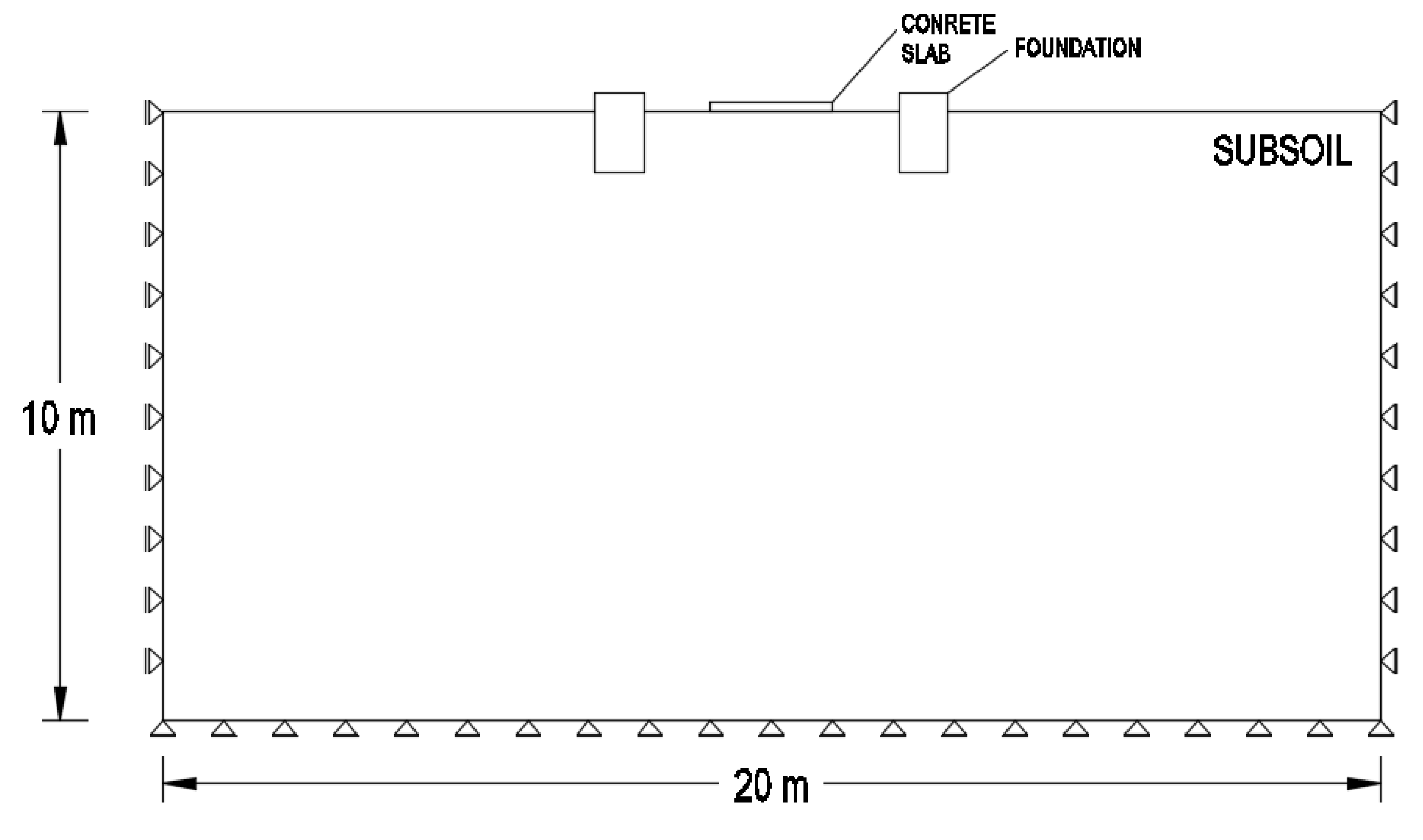
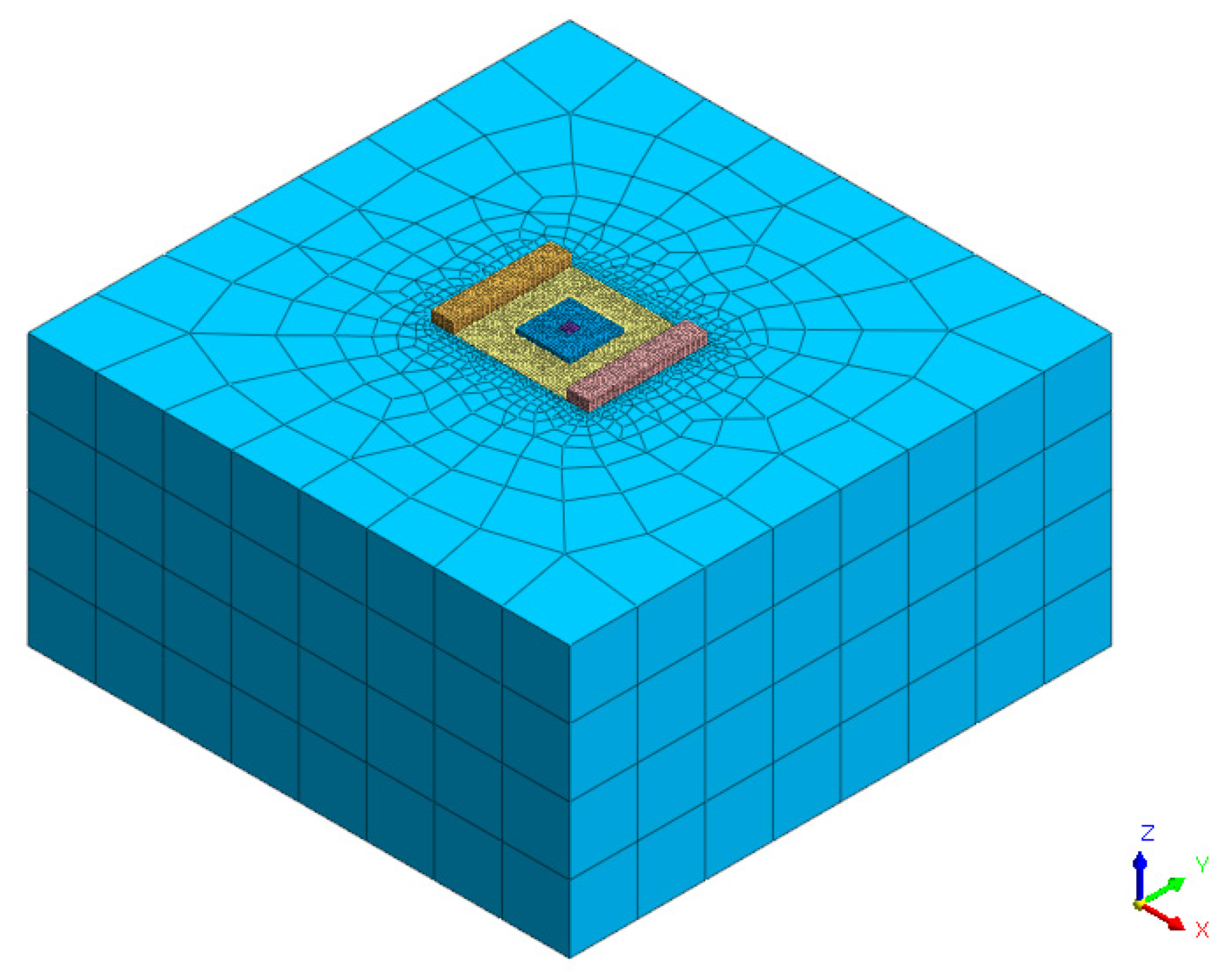
2.2. Numerical Modelling of the Fibre Slab-Subsoil Interaction

The 3D numerical simulation of complex contact problems was done based on the specialized geotechnical software MIDAS GTS NX (using finite element method). This geotechnical software is widely used in geotechnical practice.
The numerical model includes fundamental aspects and conditions of the above-mentioned real experiment. In addition to the fibre concrete slab and subsoil, both the distribution steel plate below the pressure piston and the lateral concrete foundation elements of the experimental steel frame were also considered in the model (Figure 1). The anchoring micropiles and the experimental steel frame itself were not included in the numerical model.
The 3D mesh of numerical model consists of irregular hexagonal 3D elements. The more precise hexagonal 3D elements were used in this model very effectively due to the simplicity of the modelled geometry based on the rectangular shape of the clusters without the complicated boundary curves (total number of elements 44,639, total number of nodes 35,927). The subsoil is implemented into the model as a block with dimensions 20 × 20 × 10 m. Standard geometrical boundary conditions were applied, displacements in the normal direction at the other outer boundaries of the model were zeroed, with the exception of the free upper surface of the model.
As in the real experiment, the external load was applied in individual load steps (Figure 2a). The dimensions of the model and fundamental basic components of the model (subsoil, fibre concrete slab, lateral foundations of the experimental steel frame) are shown in the Figure 4. The 3D finite element mesh of the model is shown in the Figure 5.
The widely used elastic-perfectly plastic Mohr-Coulomb constitutive model was applied to describe the soil behaviour under the slab in the numerical model. This type of soil constitutive model is commonly used in the geotechnical practice, due to the simple characterization of its strength parameters (cohesion, friction angle). Unlike an unloading problem (tunnel excavation etc.), Mohr-Coulomb model is suitable to the modelling of loading effect, including presented interaction task.
Concrete is a heterogeneous, cohesive-frictional material and exhibits complex non-linear inelastic behaviour. In applied geotechnical MIDAS GTS NX software, the elastic, Tresca, von Mises, Mohr-Coulomb, Drucker-Prager, and Hoek Brown constitutive models are available for the characterization of concrete behaviour [38]. From the point of view of theory of elasticity, elastic criterion underdetermines the state after exceeding limit value of stresses (criterion of plasticity). One-parameter Tresca model, based on the maximum shear stress theory, requires only one material parameter to define the yield surface of concrete. Von Mises yield criterion is commonly used for metal (having equal strength in tension and compression). The strength of concrete in tension and compression is different, thus, one-parameter models cannot predict the behavior of concrete in a general state of stress and therefore models with more parameters are necessary. Mohr-Coulomb and Drucker-Prager are widely used two-parameter models.
Our study is focused on the utilization and comparison of following constitutive models of slab material – elastic, Mohr-Coulomb (M/C) and Drucker-Prager (D/P). Both previously mentioned elastic-perfectly plastic constitutive models (without any strain – stiffness relation) require five input characteristics – modulus of elasticity, Poisson’s ratio, friction angle, cohesion and dilatation angle.
Mohr-Coulomb elastic-perfectly plastic model has two basic differences in comparison with the standard Drucker-Prager elastic-perfectly plastic model. Firstly, the predicted yield strength is independent on the intermediate principal stress in the Mohr-Coulomb criterion, which leads generally to the underestimation of yield strength. The second characteristic of Mohr-Coulomb model is connected to the non-smooth shape of yield surface in the principal stress space (irregular hexagon) resulted into the numerical problem with convergence. The Drucker-Prager constitutive model with a cone yield surface in the principal stress space is generally a smooth approximation to the Mohr-Coulomb criterion.
Contact elements were used in this numerical study to describe more correctly the mutual contact between the structure and soil. These contact elements were used to simulate the thin zone of shearing material at the contact and the discontinuous load transfer through the contact of two materials. They can take into account the fact that the contact of the soil with the concrete slab will cause shear failure much sooner than in the soil itself. A contact element is a zero-thickness element (the nodal points on the contact are doubled) expressing the relationship between the contact stresses and the relative change in displacements along the contact. Interface element generation separates the connected nodes of their initial position and creates an element with the specific stiffness in the normal and tangent directions. Contact elements are most often defined by their virtual thickness tv and a strength reduction coefficient R.
The strength reduction coefficient R reduces the shear parameters of the contact soil, it varies from 0 to 1. This reduction approach corresponds to the real soil-structure behaviour, where the interface is weaker and more flexible than the contact soil. This coefficient R relates the interface strength (wall friction and adhesion) and the soil strength (cohesion and friction angle). There is a lack of satisfying accurate information regarding the value of suitable reduction coefficient, but certain recommendations are formulated depending on the material of the structure and the soil characteristics. As recommended in the manual [38], this coefficient R changes in the interval 1.0–0.8 for concrete/sand contact and in the interval 1.0–0.7 for the concrete/clay contact.
Recommended value of virtual thickness tv is a value between 0.01 and 0.1 and characterizes the degree in stiffness difference between the two adjacent materials. The higher the stiffness difference between soil and structure is observed, the smaller value of tv should be applied. The higher virtual thickness is set, the more elastic deformation is generated [38].
The stiffness of the contact element is defined by the two characteristics—the normal and shear stiffness. These contact characteristics are based on the oedometric interface module Eoed,i, the shear module of interface Gi, Poisson’s ratio of interface μi = 0.45 (this high value of Poisson’s ratio simulates the non-compressive frictional behaviour of contact) and shear modulus of soil Gsoil [38]:
Eoed,i = 2 Gi ((1 − μi))/((1 − 2μi))
Gi = R · Gsoil,
The normal stiffness kn, shear stiffness kt and strength Ci of the contact can be expressed in the following forms:
kn = Eoed,i/tv,
kt = Gi/tv
Ci = R · Csoil
From the above relations can be seen that reduced coefficient R not only reduces the interface strength, but also the interface stiffness.
The slab and subsoil input material characteristics corresponded to the Table 1 and Table 2. Within the performed sensitivity analysis, the strength and deformational characteristics of subsoil were changed. The input shear strength parameters of the slab material (cohesion and friction angle of fibre concrete) for the above mentioned elastoplastic constitutive models were determined based on the Mohr-Coulomb envelope using both the tensile and compressive strength of fibre concrete. The cohesion of the fibre concrete was evaluated 3.94 MPa and the friction angle 55°.

3. Results

The obtained results of the numerical parametric study can be divided into the four basic parts:
  • evaluation of the dependence of the vertical displacements of the slab on the applied constitutive model of the slab material (assuming identical input characteristics of Mohr-Coulomb and Drucker-Prager model), comparison of results
  • assessment of vertical displacements and deflection of slab corresponding to the variant shear strength parameters of subsoil assuming Mohr-Coulomb model of both slab and subsoil (without interface elements), comparison with monitored results
  • assessment of vertical displacements and deflection of slab corresponding to the variant Young’s modulus of subsoil assuming Mohr-Coulomb model of both slab and subsoil (without interface elements), comparison with monitored results
  • evaluation of interface elements effect on the vertical displacements and deflection of the slab assuming Mohr-Coulomb model of both slab and subsoil, comparison with monitored results
Vertical displacements of the reference cross-section (see Figure 2b) of the slab were considered as the main calibration criterion of modelling.

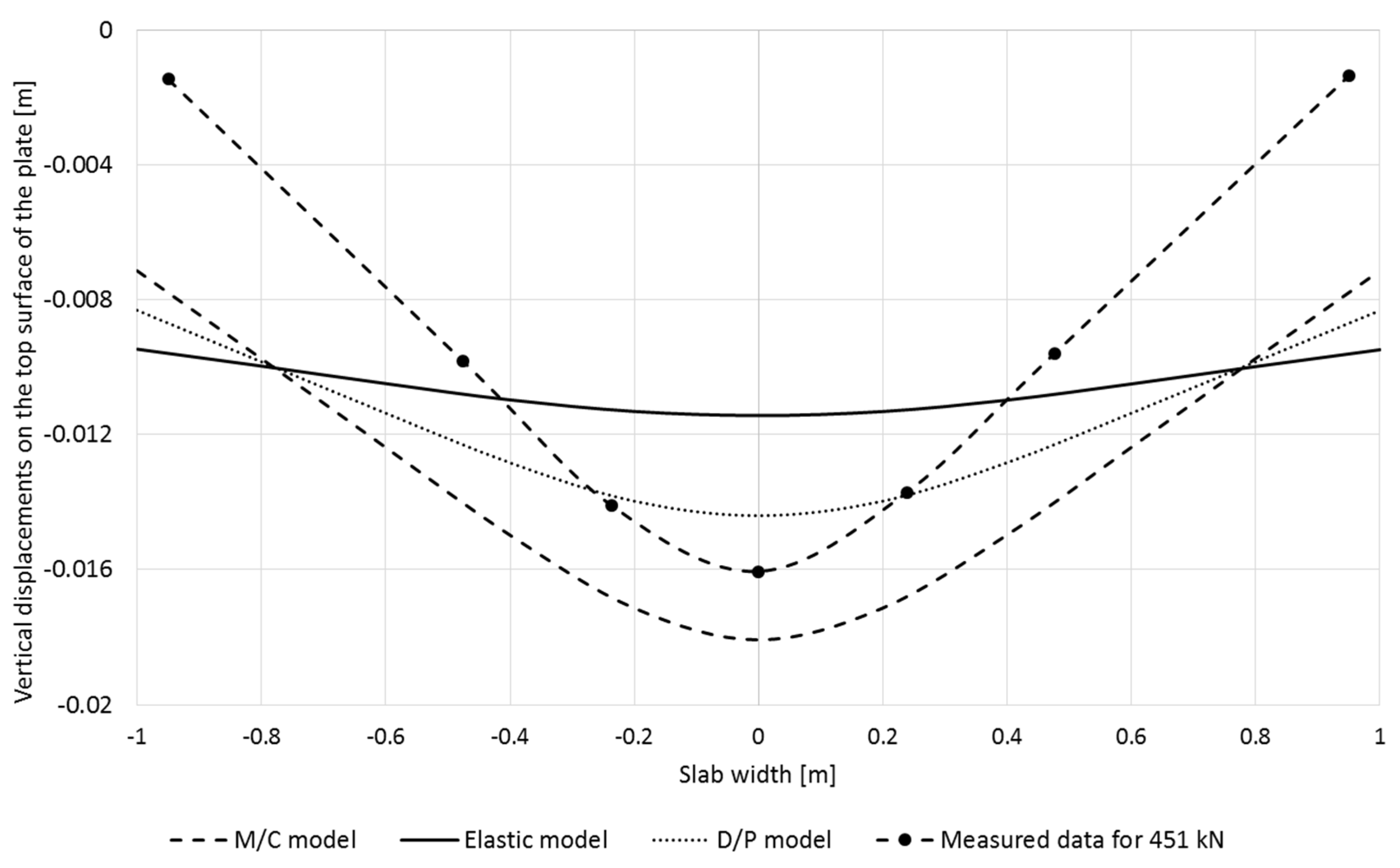
3.1. Evaluation of the Dependence of the Vertical Displacements of the Slab on the Applied Constitutive Model of the Slab Material

A comparison of the impact of the applied material constitutive model of slab on vertical displacements of the slab surface, corresponding to the load of 451 kN (load before the failure initiation), is shown in Figure 6. The input characteristics of slab material correspond to the Table 1, characteristics of the subsoil correspond to the Table 2. The comparison of deflection curve, corresponding to the different constitutive models assuming identical input values and boundary conditions, was performed both qualitatively and quantitatively. The vertical displacements of the upper surface of the slab and the corresponding deflection were chosen as the determining criterion for comparison due to the existence of the real experimentally measured values of these displacements.
The shape of deflection curve, based on the Mohr-Coulomb model, is in greater agreement with the measured deflection curve in comparison with the Drucker-Prager model. Deflection curves corresponding to the both elastic and Drucker-Prager model are flatter.
From the quantitative point of view, the Mohr-Coulomb model overestimated the experimental results of vertical displacements and, with the exception of the parts adjacent to the edges of the slab, also the results based on the D/P model. The numerical results of maximum vertical displacements confirmed the conservative character of the Mohr-Coulomb model compared to the Drucker-Prager model (influence of intermediate principal stress in Drucker-Prager model was manifested) assuming the identical input material characteristic. Drucker-Prager model underestimated the experimental results in the central part of slab (compressive stressed part of slab). On the other hand, towards the edges of the plate (tensile stressed part of slab) the results of the Drucker-Prager model overestimated the values of the vertical displacements in comparison with the measurement results.
For the elastic constitutive model, assuming the arise of infinite stresses to the limitless strength, the maximum values of elastic vertical displacements near the central part of the slab are considerably lower compared to measured values (assuming identical deformational input material characteristics as for the elastic-perfectly plastic models). Additionally, the deflection curve has significantly lower gradient from the centre towards the edges of slab compared to both the measured data and the results of both considered elastoplastic constitutive models. Assuming the elastic constitutive model of slab, the displacement curve is flatter and does not have a significant maximum in the centre of the slab (deflection is significantly lower).
Finally, full quantitative and qualitative agreements of the results of the numerical model with the experimental results were not fully achieved with the application of both Mohr-Coulomb and Drucker-Prager constitutive models of slab material. Soil characteristics were not changed in this calculation and they corresponded to the values given in Table 2. In this task the Mohr-Coulomb model better characterizes the shape of measured deflection curve of the slab in comparison with the Drucker-Prager model. Regarding the maximum vertical displacement in the centre of the slab (under the compressive stressed part of slab), the measured values were not achieved assuming both the Mohr-Coulomb and the D/P constitutive models. Mohr-Coulomb overestimated the maximum vertical displacements in the slab centre, while Drucker-Prager underestimated this maximum value for the same input data. In the tensile stressed part of slab both elastoplastic constitutive models overestimated the measured vertical displacements.

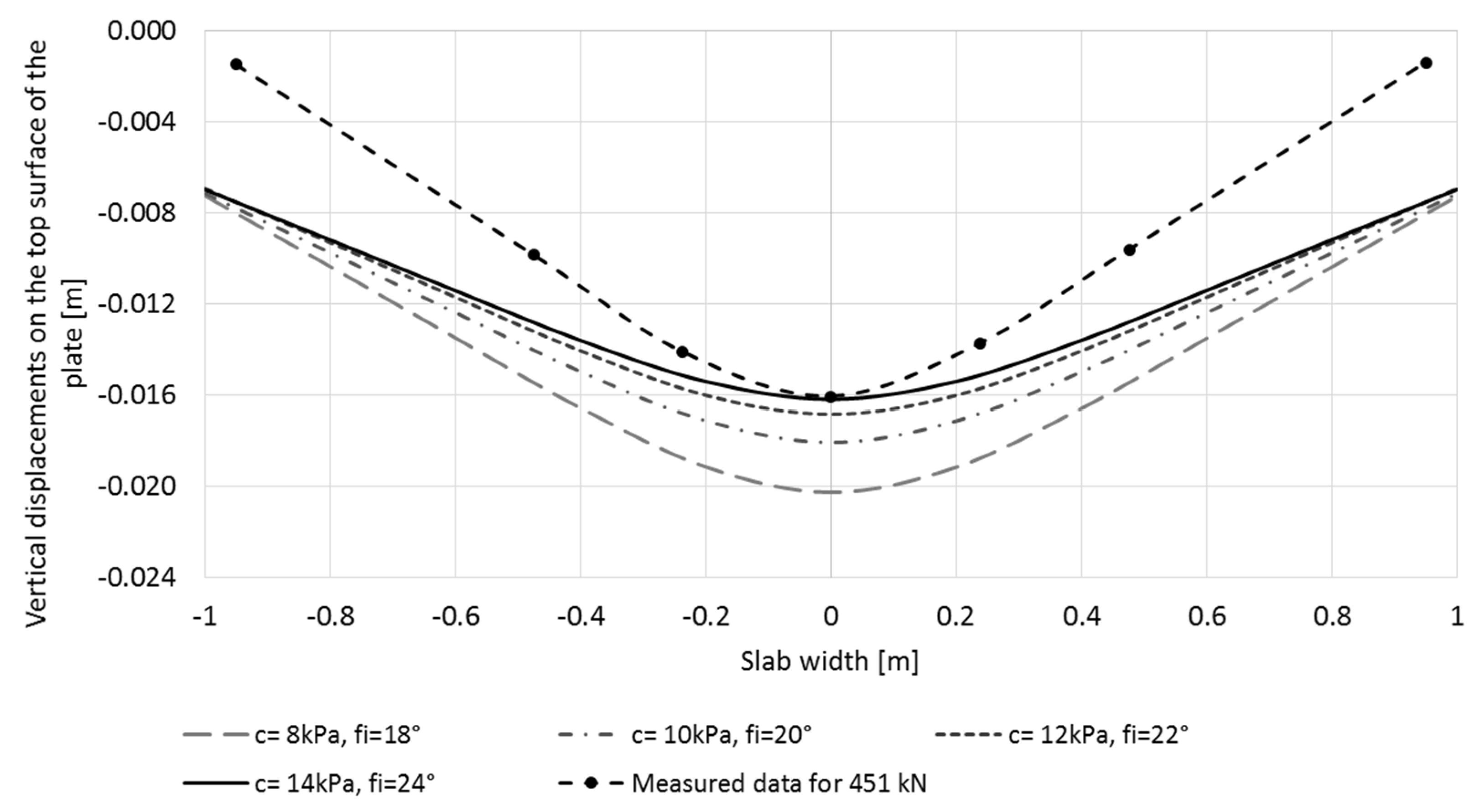
3.2. Assessment of Vertical Displacements and Deflection of Slab Corresponding to the Variant Shear Strength Parameters of Subsoil Assuming Mohr-Coulomb Model of Both Slab and Subsoil (without Interface Elements), Comparison with Monitored Results

Mohr-Coulomb constitutive model of both fibre concrete and subsoil material was used to the sensitivity analysis regarding the shear strength parameters of subsoil, with the aim of achieving better agreement with the measured data. The results of numerical simulation were compared with the monitored values of the vertical displacements of the upper surface of the slab. The shear strength parameters of subsoil were changed, while the other input characteristics remained unchanged in this study.
The results of the sensitivity analysis, assuming variant shear strength characteristics of subsoil material and loading 451 kN, are shown in Figure 7. The presented results confirmed that the changes in shear strength of subsoil affect significantly the maximum vertical displacements in the centre of slab. The higher shear strength parameters were applied, the lower calculated central vertical displacements were assessed. The influence of these shear strength parameters on the vertical displacements decreased towards the edges of the tested slab, this influence was practically negligible near the edges of the slab at the considered load 451 kN (the plastic deformations inside the subsoil were not manifested under the edges of slab due to the gradual lifting of the investigated slab and the gap occurrence under the edges of it). The performed parametric study show that the cohesion of 14 kPa and internal friction angle of 24° make possible to achieve the best agreement of the maximum calculated and measured vertical displacements in the centre of the slab (assuming Young’s modulus of subsoil 12 MPa).
However, from the qualitative point of view, the calculated and experimentally obtained shape of vertical displacement curve was inconsistent. The gradient of calculated curve of vertical displacements was lower towards the edges of the slab in comparison to the measured curve (lower modelled deflection was assessed). While the strength characteristics of the subsoil decreased, the gradient of calculated curve increased and corresponded better to the measured curve, but the consistency was not achieved from the quantitative point of view.
These results confirmed that the numerical model without the application of contact elements (assuming the elasto-perfectly plastic Mohr-Coulomb model without the strain-stiffness dependency) is not able to fully describe the slab-subsoil interaction both from the qualitative and quantitative point of view. It was possible to obtain the real information about the maximal vertical displacements in the centre of the slab, but the results of deflection were not reliable.
The Figure 8 shows the curve of the maximal experimental vertical displacements under the centre of the slab, corresponding to the load higher than 451 kN (a crack initiation was observed at this load)-In addition, the comparison with the calculated results (assuming Mohr-Coulomb model, c = 14 kPa, ϕ = 24°, no interface element) was presented in this figure. These experimentally observed vertical displacements were significantly influenced by (i) the stress concentration in the central part of the slab due to the lifting of both the corners and edges of the slab during deflection (reduction of contact area) and (ii) the slab failure (punching) initiation in the central part of slab. The higher the applied load, the higher the deflection of the slab, the higher reduction of the contact area and the higher lifting of the edges and corners of the slab were observed (lifting of the edge of 7 mm, corresponding to the maximum failure load 593 kN, was measured). This state (after the more significant lifting manifestation) was characterized by the increased differences in vertical displacements between the center and edges of the slab.
The model results show that, in all applied load steps, including the final load of 593 kN at failure, extreme calculated vertical displacements in the center of slab almost match the measured values very well, but the calculated deflection of slab is lower compared to the experiment. Unlike the experiment, the numerical model was not able to reflect the decrease of vertical displacements at the edges of the slab when the load was increased. An increase in load of slab resulted in an increase in maximal vertical displacement value in the central part of the slab, but the calculated vertical displacement at the edges of slab remained the same, regardless of the slab load (cracks and gradual failure occur in the central part of the slab).

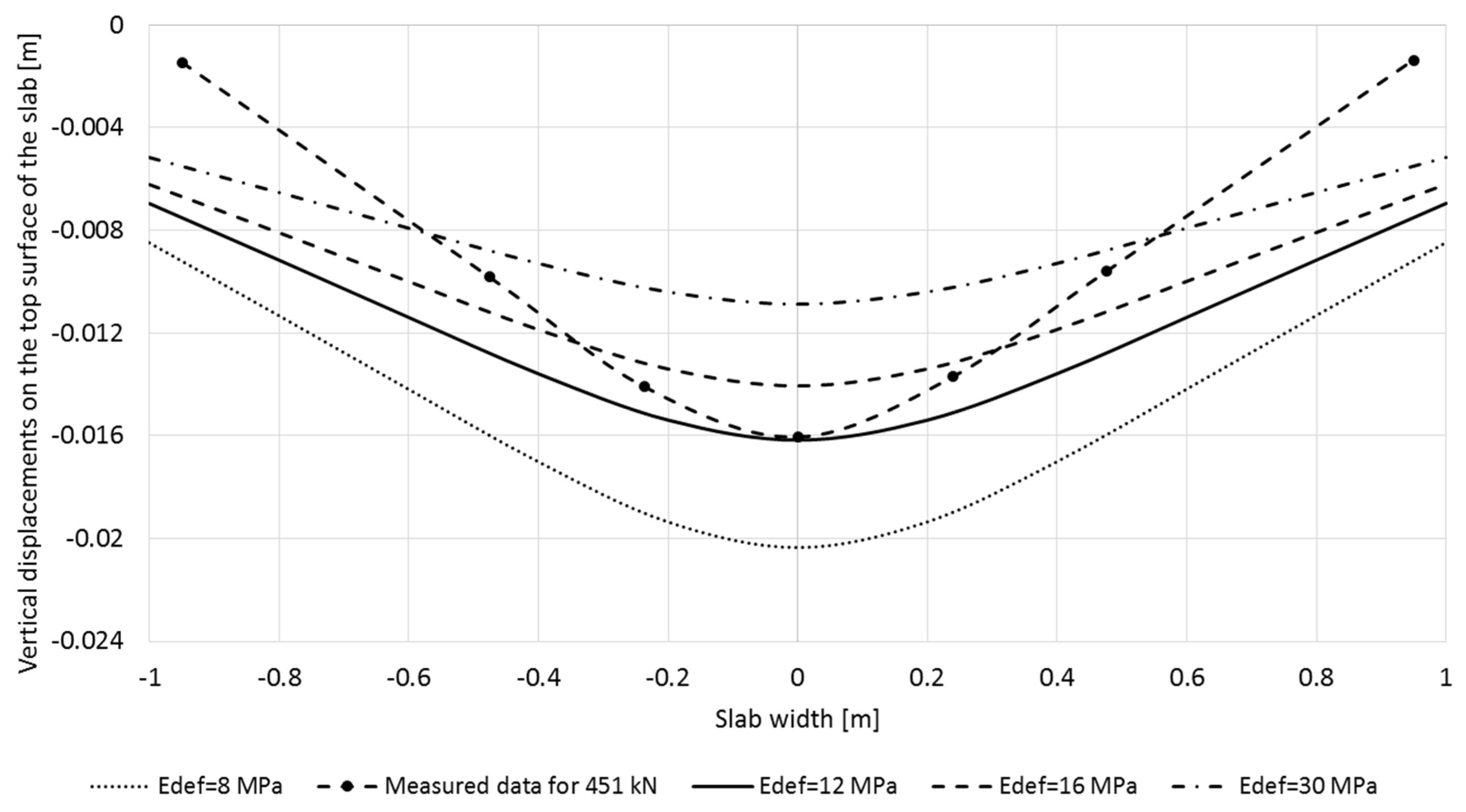
3.3. Assessment of Vertical Displacements and Deflection of Slab Corresponding to the Variant Young’s Modulus of Subsoil Assuming Mohr-Coulomb Model of Both Slab and Subsoil (without Interface Elements), Comparison with Monitored Results

This part of paper is also focused on the sensitivity of calculated vertical displacement of slab on the deformational modulus of subsoil assuming Mohr-Coulomb model of slab and subsoil. Cohesion of 14 kPa and friction angle of 24° were assumed as the shear strength parameters of subsoil in this study. The parametric numerical calculations were done with the variant deformational modulus of subsoil (8 MPa, 12 MPa, 16 MPa and 30 MPa).
As can be seen from Figure 9, the qualitative agreement between the calculated and measured deflection curve was not achieved by these changes in the deformational characteristics of the subsoil, although the change in the modulus of deformation of subsoil affected the maximum value of vertical displacement in the centre of the slab. The best fitting corresponds to the Young’s modulus of subsoil 12 MPa in this study.

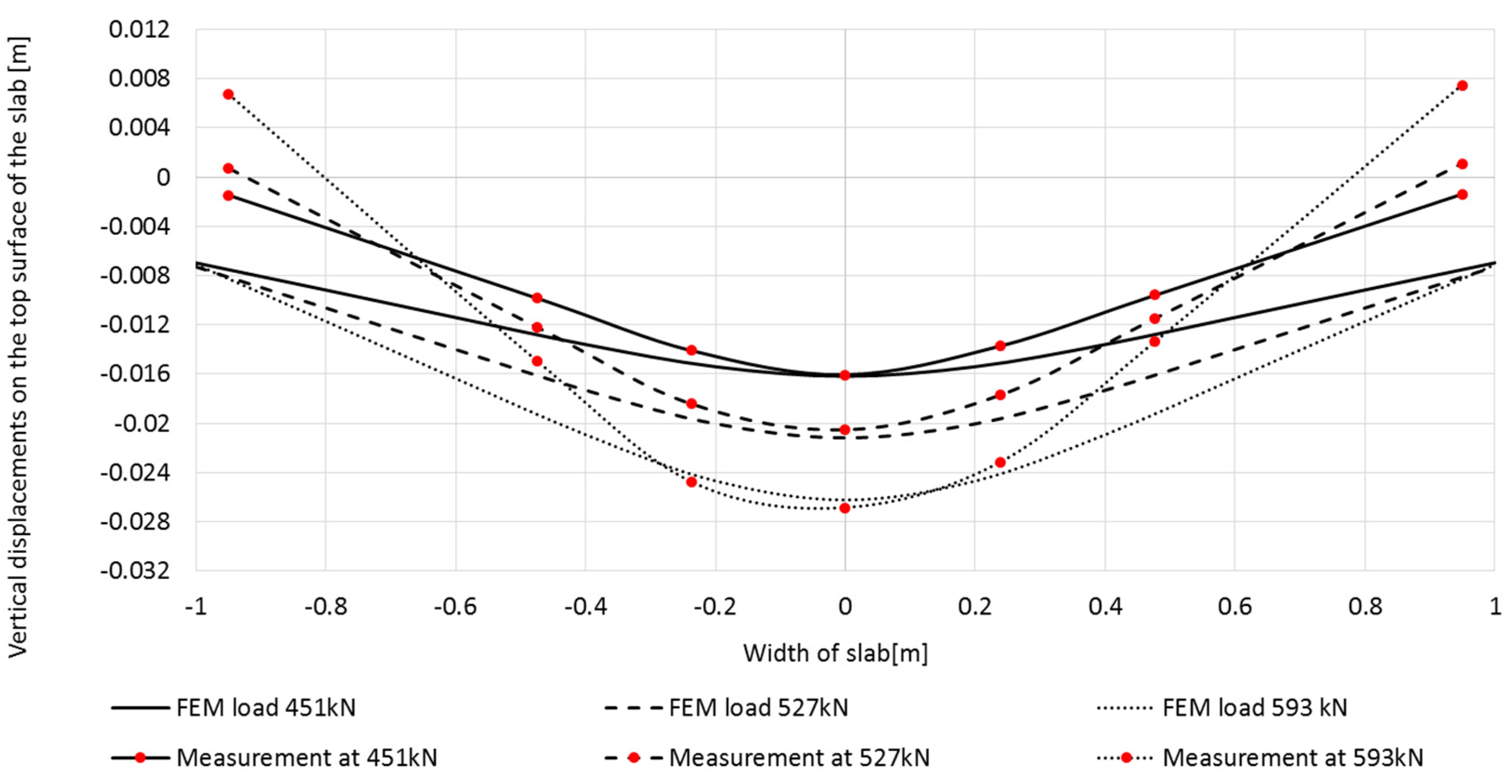
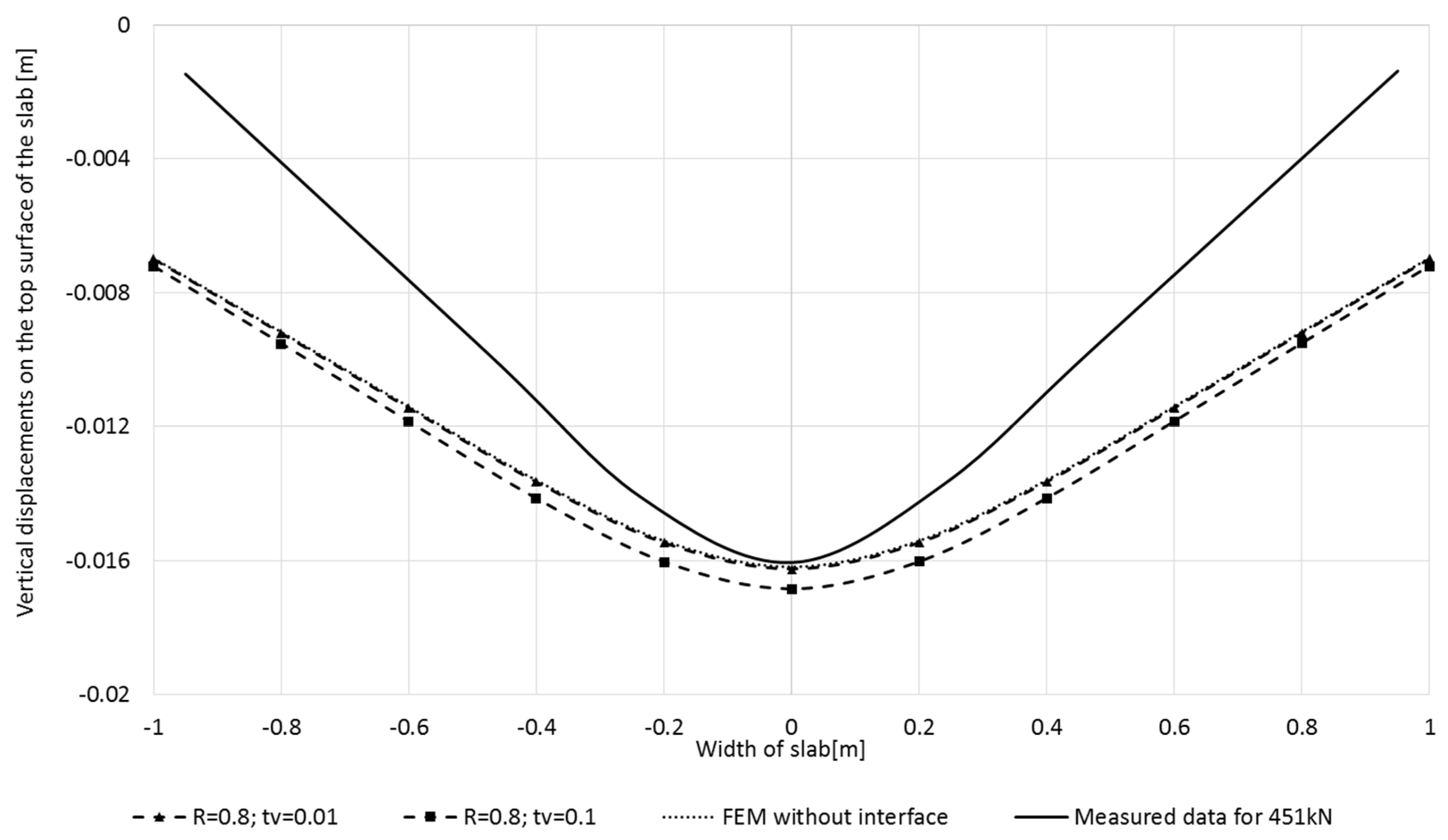
3.4. Evaluation of Interface Elements Effect on the Vertical Displacements of the Slab

As was previously mentioned, both the edges and corners of the slab were lifted at specific load in the experiment, a gap was created between the slab and the subsoil and the contact between the slab and subsoil was disturbed. This in-situ observed discontinuity occurrence between the deformation of the subsoil and the slab does not correspond to the assumption for the application of 3D finite elements, which primarily assumes a continuous deformation both contacting material. The implementation of contact (interface) elements is one way to involve the discontinuous contact behaviour of both materials.
The effect of the virtual thickness parameter is shown in Figure 10 assuming the reduction coefficient R = 0.8 (usually used value R for the concrete structure contact [38]). Firstly, the calculations were done with the varying virtual thickness corresponding to the boundary values of recommended interval (both tv = 0.1 and tv = 0.01) for the external load 451 kN.
For tv = 0.01, the calculated vertical displacement curve corresponds to the results without the interface (there is no interface effect), very small increments of displacements were evaluated for a virtual thickness of 0.1. These results confirmed the fact (see Section 2) that, due to the high stiffness difference between the soil and concrete, the smaller value of tv should be applied in this case. These results documented that for the partial external loading of 451 kN the interface impact is not manifested significantly.
At higher loads, the modelled results of the contact between the slab and subsoil already showed the more significant influence of the contact element application. The effect is evident both on the development of contact stresses and on the uplift of the corners of the modelled slab. The corresponding development of contact stresses in all loading steps from 150 to 593 kN (step load increment approx. 75 kN), assessed by the finite element model assuming tv = 0.01, R = 0.8, is presented in the Figure 11. A gradual redistribution of the extremal vertical contact stresses from a local area under the steel load plate (center of the slab) to the formation of two stress concentration areas, located approx. 0.4 m from the center of slab, was observed for loads greater than 300 kN (from loading step 3). These stress extremes about 1000 kPa at the last loading step 593 kN was obtained. This contact stress curve seems to correspond to the experimentally observed failure of the slab together with the formation of plastic areas in the subsoil under the center of slab and to the gapping occurrence between the slab and subsoil (Figure 3).
The modelled deformed shape of the slab is shown in Figure 12. Thus, by introducing the contact element into the model, the corners of the slab were lifted from the ground at higher applied external loading in the model, which is consistent with the results of the experiment.

4. Conclusions

The topic of the paper is focused on the numerical parametric study of the interaction of the fibre concrete slab with the subsoil using geotechnical software MIDAS GTS NX. The calibration of the numerical models was performed based on the results of experimental measurements of vertical displacements on the upper surface of experimentally investigated fibre concrete slab. Based on the performed 3D numerical study the following conclusions were formulated:
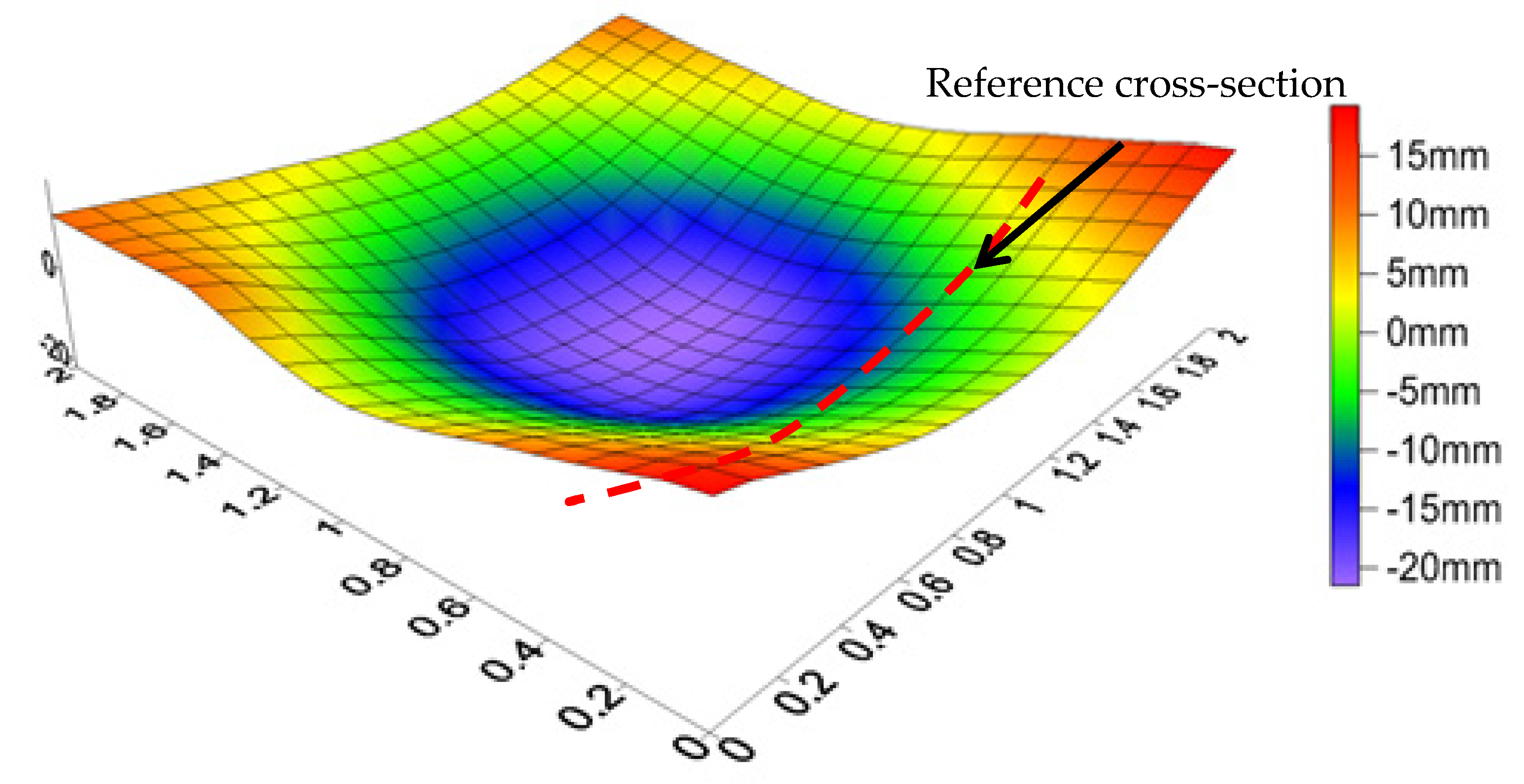
  • From the quantitative point of view the Mohr-Coulomb model of slab overestimated both the results of vertical displacements of slab based on the elastic or Drucker-Prager model and experimental results (the difference between the max. vertical displacements assuming Mohr-Coulomb model and experimental measurements achieved 12% in this study). Thus, Mohr-Coulomb model of slab (assuming Mohr-Coulomb model of subsoil) assessed the maximal vertical displacements of the centre of slab on the safety side. The measured maximum vertical displacement in the centre of the slab (under the compressive stressed part of slab) was not achieved with the elastic, Mohr-Coulomb and the Drucker-Prager constitutive models. Mohr-Coulomb overestimated the maximum vertical displacements in the slab centre, while Drucker-Prager underestimated this maximum value for the same input data. In the tensile stressed part of slab both elastoplastic constitutive models overestimated the measured value of vertical displacements. Elastic model underestimated the experimental results (about 37%).
  • From the qualitative point of view (shape of deflection curve), the numerical simulation showed the better agreement of the Mohr-Coulomb constitutive model with the experimental measurements in comparison with both other constitutive models. Unlike the elastic and Drucker-Prager model, the curves of both measured and calculated vertical displacements using Mohr-Coulomb model were characterized by the significant differences between the centre of slab and its edge, which corresponds better with the observed real behaviour of slab. But even with the application of Mohr-Coulomb model, experimentally investigated greater deflection was not achieved. Thus, none of the considered constitutive models was able to capture the real shape of the deflection curve in this study, the model indicated smaller deflections of the slab.
  • The results, assuming elastic constitutive model, confirmed the unsuitability of the application of this simple elastic constitutive model to the modelling of slab-subsoil interaction from both qualitative and quantitative point of views.
  • Assuming Mohr-Coulomb constitutive model of slab without the interface, the shear strength characteristics of subsoil (cohesion and friction angle) affected the maximum vertical displacements in the centre of slab, but there is no effect on the vertical displacements at the edges after the lift of a boundary parts of slab was manifested. With the reduction of the shear strength characteristics of the subsoil, a larger deflection of the slab was achieved in the model, but nevertheless the experimentally measured deflection curve (reflected in internal forces inside of slab) was achieved by the numerical model based on the Mohr-Coulomb constitutive model.
  • The Mohr-Coulomb model of slab without interface showed that the calculated vertical displacement of the edges of slab remained the same regardless of the slab load after the lift of a boundary part of the slab was manifested. Of course, the maximum vertical displacements in the centre of slab increased with increasing load.
  • The change of deformation characteristics in the subsoil did not lead to the achievement of the measured deflection of the slab after the lift of a boundary part of slab was manifested. Only the maximum vertical measured displacement in the centre of slab was achieved by the model changing the subsoil strength and deformational characteristics.
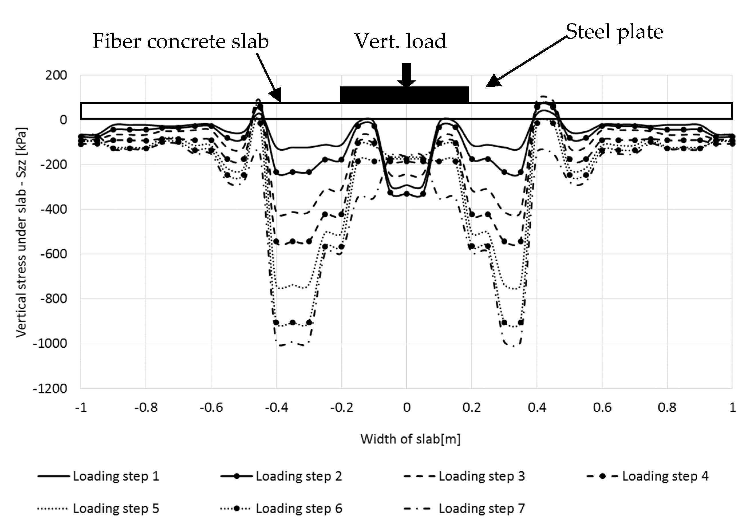
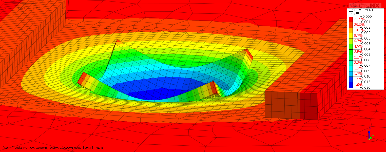
  • The need to apply contact (interface) elements has been shown in this study. These elements can to take into account the reduction of the contact area between the slab and the subsoil resulted from the experimentally observed significant deflection and gapping occurrence between the slab and the subsoil. The effect of interface elements was not significant in case of lower load without manifestation of significant plastic deformation. But for the higher load, the application of contact elements in the model led to a more realistic view of the slab-subsoil interaction, to the redistribution of contact stress in the subsoil from the central part towards the edges and to the lift of the corners of the slab.
  • Numerical model based on the finite element method (using MIDAS GTS NX software), assuming Mohr-Coulomb constitutive model for both of slab and subsoil material, can be used to the modelling of slab- subsoil interaction, but certain above mentioned limitations of the modelling results should be taken into account. Especially, assuming elastic, Mohr-Coulomb or Drucker-Prager constitutive model, modelled deflection and the resulting internal forces inside the slab could be underestimated.
  • To obtain more reliable results from of the both qualitative and quantitative points of view, it would be necessary to apply more advanced constitutive models of both subsoil and fibre concrete slabs, considering the hardening and softening phenomenon of material and the partial loss of stiffness due to the cracking of concrete [44]. Attention must be also paid to further study of the properties and the behaviour of interface elements and to other numerical methods, including mesh free methods of cracks mechanics [45,46].
  • The performed study confirmed that the problem of slab-subsoil interaction is associated significantly with both the geotechnical and structural engineering. Every user of specialized software, whether geotechnical or structural, should be aware of the fact that certain aspects of the previously mentioned engineering areas are emphasized at the expense of others in this software. In specialized geotechnical software (MIDAS GTS NX, PLAXIS, etc.) the structural elements are usually more simplified (often only their elastic behaviour is considered), but the subsoil can be modelled in the more details. On the other hand, the specialized structural software (ANSYS, SCIA Engineer etc.) have option to detailed modelling of structural element behaviour, but the subsoil behaviour is usually more simplified. This fact is necessary to consider when assessing the reliability of the results of numerical models. It is optimal to verify the results of modelling by monitoring, as was done in this presented contact problem.

Author Contributions

Conceptualization, L.D. and E.H.; methodology, E.H.; software, L.D.; validation, L.D.; writing—original draft preparation, L.D.; writing—review and editing, E.H.; visualization, L.D.; supervision, E.H.; project administration, L.D. All authors have read and agreed to the published version of the manuscript.

Funding

This research was funded by VŠB-TUO by the Ministry of Education, Youth, and Sports of the Czech Republic.

Acknowledgments

The work was supported by the conceptual development of science, research, and innovation, assigned to VŠB-TUO by the Ministry of Education, Youth and Sports of the Czech Republic.

Conflicts of Interest

The authors declare no conflict of interest.

References

  1. Vandewalle, L.; Nemegeer, D.; Balazs, G.L.; Barr, B.; Bartos, P.; Banthia, N.; Brandt, A.M.; Criswell, M.; Denarie, F.; di Prisco, M.; et al. Recommendations of RILEM TC 162-TDF: Test and design methods for steel fibre reinforced concrete Uni-axial tension test for steel fibre reinforced concrete. Mater. Struct. 2005, 34, 3–6. [Google Scholar] [CrossRef]
  2. Sucharda, O.; Bilek, V. Aspects of Testing and Material Properties of Fiber Concrete. Solid State Phenom. 2019, 292, 9–14. [Google Scholar] [CrossRef]
  3. Marar, K.; Eren, O.; Roughani, H. The influence of amount and aspect ratio of fibers on shear behaviour of steel fiber reinforced concrete. KSCE J. Civ. Eng. 2016, 21, 1393–1399. [Google Scholar] [CrossRef]
  4. Song, P.S.; Hwang, S. Mechanical properties of high-strength steel fiber-reinforced concrete. Constr. Build. Mater. 2004, 18, 669–673. [Google Scholar] [CrossRef]
  5. Swamy, R.; Lankard, D.R. Some practical applications of steel fibre reinforced concrete. Proc. Inst. Civ. Eng. 1974, 56, 235–256. [Google Scholar] [CrossRef]
  6. Brandt, A.M. Fibre reinforced cement-based (FRC) composites after over 40 years of development in building and civil engineering. Compos. Struct. 2008, 86, 3–9. [Google Scholar] [CrossRef]
  7. Elsaigh, W.A. A Comparative Evaluation of Plain and Steel Fiber Reinforced Concrete Ground Slabs. Master’s Thesis, University of Pretoria, Pretoria, South Africa, 2001. [Google Scholar]
  8. Falkner, H.; Huang, Z.; Teutsch, M. Comparative study of plain and steel fiber reinforced concrete ground slabs. Concr. Int. 1995, 17, 45–51. [Google Scholar]
  9. Meier, A. Typical damage to industrial floors built in concrete and steel-fiber reinforced concrete. Betonw. Und. Fert. Tech. Concr. Plant Precast Technol. 2011, 77, 174–175. [Google Scholar]
  10. Pollak, P.; Zlatinska, L. Influence of subsoil quality on design of slab foundation. In Roczniki Inzynierii Budowlanej; Zeszyt: Katowice, Poland, 2013; Volume 13, ISSN 1505-8425. [Google Scholar]
  11. Tomasovicova, D.; Jendzelovsky, N. Stiffness Analysis of the Subsoil under Industrial Floor. Procedia Eng. 2017, 190, 365–370. [Google Scholar] [CrossRef]
  12. Hegger, J.; Ricker, M.; Ulke, B.; Ziegler, M. Investigations on the punching behaviour of reinforced concrete footings. Eng. Struct. 2007, 29, 2233–2241. [Google Scholar] [CrossRef]
  13. Shentu, L.; Jiang, D.; Hsu, C.-T.T. Load-Carrying Capacity for Concrete Slabs on Grade. J. Struct. Eng. 1997, 123, 95–103. [Google Scholar] [CrossRef]
  14. Sucharda, O.; Smirakova, M.; Vašková, J.; Matečkov, Á.P.; Kubosek, J.; Čajka, R. Punching Shear Failure of Concrete Ground Supported Slab. Int. J. Concr. Struct. Mater. 2018, 12, 36. [Google Scholar] [CrossRef]
  15. Čajka, R.; Burkovič, K.; Buchta, V. Foundation Slab in Interaction with Subsoil. Adv. Mater. Res. 2013, 838, 375–380. [Google Scholar] [CrossRef]
  16. Čajka, R.; Vašková, J.; Labudková, J. Fibre Concrete Foundation Slab Experiment and FEM Analysis. Key Eng. Mater. 2014, 627, 441–444. [Google Scholar] [CrossRef]
  17. Čajka, R. Experimetal measurement of soil-prestressed foundation interaction. Int. J. GEOMATE 2016, 10, 2101–2108. [Google Scholar] [CrossRef]
  18. Barros, J.A.; Figueiras, J.A. Experimental behaviour of fibre concrete slabs on soil. Mech. Cohesive-Frict. Mater. 1998, 3, 277–290. [Google Scholar] [CrossRef]
  19. Sorelli, L.G.; Meda, A.; Plizzari, G. Steel Fiber Concrete Slabs on Ground: A Structural Matter. ACI Struct. J. 2006, 103, 551–558. [Google Scholar] [CrossRef]
  20. Alani, A.M.; Aboutalebi, M. Analysis of the subgrade stiffness effect on the behaviour of ground-supported concrete slabs. Struct. Concr. 2012, 13, 102–108. [Google Scholar] [CrossRef]
  21. Alani, A.M.; Rizzuto, J.; Beckett, D.; Aboutalebi, M. Structural behaviour and deformation patterns in loaded plain concrete ground-supported slabs. Struct. Concr. 2014, 15, 81–93. [Google Scholar] [CrossRef]
  22. Siburg, C.; Hegger, J. Experimental investigations on the punching behaviour of reinforced concrete footings with structural dimensions. Struct. Concr. 2014, 15, 331–339. [Google Scholar] [CrossRef]
  23. Alani, A.; Beckett, D.; Khosrowshahi, F. Mechanical behaviour of a steel fibre reinforced concrete ground slab. Mag. Concr. Res. 2012, 64, 593–604. [Google Scholar] [CrossRef]
  24. Huang, X.; Liang, X.; Liang, M.; Deng, M.; Zhu, A.; Xu, Y.; Wang, X.; Li, Y. Experimental and theoretical studies on interaction of beam and slab for cast-in-situ reinforced concrete floor structure. J. Build. Struct. Jianzhu Jiegou Xuebao 2013, 34, 63–71. [Google Scholar]
  25. Le, T.D.; Nguyen, Q.T.; Cajka, R. Numerical Analysis of Subsoil-Reinforced Concrete Slab Interaction. Sect. Build. Struct. Struct. Mech. 2018, 18. [Google Scholar] [CrossRef] [Green Version]
  26. Breeveld, B.J.S. Modelling the Interaction between Structure and Soil for Shallow Foundations-A Computational Modelling Approach. Ph.D. Thesis, Delft University of Technology, Delft, The Netherlands, 2013. [Google Scholar]
  27. Dutta, S.C.; Roy, R. A critical review on idealization and modeling for interaction among soil–foundation–structure system. Comput. Struct. 2002, 80, 1579–1594. [Google Scholar] [CrossRef]
  28. Boswell, L.F.; Scott, C.R. A flexible circular plate on a heterogeneous elastic half-space: Influence coefficients for contact stress and settlement. Géotechnique 1975, 25, 604–610. [Google Scholar] [CrossRef]
  29. Brown, P.T. Numerical analysis of uniformly loaded circular rafts on elastic layers of finite depth. Geotechnique 1969, 19, 301–306. [Google Scholar] [CrossRef]
  30. Labudkova, J.; Cajka, R. Comparison of Analysis of Linear Inhomogeneous and Nonlinear Half-Space in Foundation-Subsoil Interaction. Internat. J. Mech. 2016, 10, 90–98. [Google Scholar]
  31. Cajka, R.; Labudkova, J. Dependence of deformation of a plate on the subsoil in relation to the parameters of the 3D model. Int. J. Mech. 2014, 8, 208–215. [Google Scholar]
  32. Labudkova, J.; Čajka, R. Numerical analyses of interaction of steel-fibre reinforced concrete slab model with subsoil. Frat. Integrità Strutt. 2016, 11, 47–55. [Google Scholar] [CrossRef] [Green Version]
  33. Genikomsou, A.; Polak, M.A. Finite Element Simulation of Concrete Slabs with various Placement and Amount of Shear Bolts. Procedia Eng. 2017, 193, 313–320. [Google Scholar] [CrossRef]
  34. K.G.S. Modelling of soil-structure interaction. Comput. Geotech. 1990, 9, 236–237. [Google Scholar] [CrossRef]
  35. Shekarbeigi, M.; Sharafi, H. Constitutive Model for Concrete: An Overview. Curr. World Environ. 2015, 10, 782–788. [Google Scholar] [CrossRef]
  36. Kralik, J.; Jendzelovsky, N. Contact problem of the reinforced concrete girder and non-linear Winkler foundations. In Geomechanics 93; Routledge: London, UK, 1994; pp. 233–236. [Google Scholar]
  37. Fwa, T.F.; Shi, X.P.; Tan, S.A. Use of Pasternak Foundation Model in Concrete Pavement Analysis. J. Transp. Eng. 1996, 122, 323–328. [Google Scholar] [CrossRef]
  38. MIDAS GTS Manual; MIDAS information Technology Co., Ltd.: Gyeonggi-do, Korea, 2017.
  39. Brinkgreve, R.B.J.; Broere, W.; Waterman, D. Plaxis 2D 2008; Plaxis B.V.: Delft, The Netherlands; ISBN 90-808079-4-X.
  40. Čajka, R.; Křivý,, V.; Sekanina, D. Design and Development of a Testing Device for Experimental Measurements of Foundation Slabs on the Subsoil. Trans. VŠB Tech. Univ. Ostrav. Civil. Eng. Ser. 2011, XI, 1–5. [Google Scholar] [CrossRef]
  41. Hrubešová, E.; Mohyla, M.; Lahuta, H.; Bui, T.Q.; Nguyen, P.D. Experimental Analysis of Stresses in Subsoil below a Rectangular Fiber Concrete Slab &dagger. Sustainability 2018, 10, 2216. [Google Scholar] [CrossRef] [Green Version]
  42. Lahuta, H.; Hrubešová, E.; Mohyla, M.; Duris, L.; Pinka, M. Assessment of Fiber Reinforced Concrete Slab and Subsoil Interaction—Experiment. Key Eng. Mater. 2018, 761, 169–172. [Google Scholar] [CrossRef]
  43. Čajka, R.; Marcalikova, Z.; Kozielova, M.; Mateckova, P.; Sucharda, O. Experiments on Fiber Concrete Foundation Slabs in Interaction with the Subsoil. Sustainability 2020, 12, 3939. [Google Scholar] [CrossRef]
  44. Babu, R.R.; Benipal, G.; Singh, A.K. Constitutive modelling of concrete: An overview. Asian J. Civ. Eng. 2005, 6. [Google Scholar]
  45. Rabczuk, T.; Zi, G.; Bordas, S.P.A.; Nguyen-Xuan, H. A geometrically non-linear three-dimensional cohesive crack method for reinforced concrete structures. Eng. Fract. Mech. 2008, 75, 4740–4758. [Google Scholar] [CrossRef]
  46. Rabczuk, T.; Belytschko, T. Cracking particles: A simplified meshfree method for arbitrary evolving cracks. Int. J. Numer. Methods Eng. 2004, 61, 2316–2343. [Google Scholar] [CrossRef]
Figure 1. Scheme of the experimental fibre slab testing.
Sustainability 12 10036 g001
Figure 2. Slab loading procedure and slab instrumentation (a) stepwise loading curve; (b) location of vertical displacements sensors, investigated cross-section for vertical displacements evaluation (dashed line).
Sustainability 12 10036 g002
Figure 3. Evaluation of experimentally measured vertical displacements of slab, including the uplift of the corners (load 451 kN) (interpolation using Surfer software was applied).
Sustainability 12 10036 g003
Figure 4. Dimension of the numerical model (cross-section).
Sustainability 12 10036 g004
Figure 5. 3D finite element mesh of the numerical model (axonometric view).
Sustainability 12 10036 g005
Figure 6. Comparison of measured vertical displacements and results of numerical simulation in reference cross-section using different constitutive material model of fibre concrete slab (451 kN loading).
Sustainability 12 10036 g006
Figure 7. Comparison of the measured and calculated results assuming different shear strength characteristics of subsoil (load 451 kN).
Sustainability 12 10036 g007
Figure 8. Comparison of the measured and calculated results for different load values (assuming Mohr-Coulomb model, c = 14 kPa, φ = 24°).
Sustainability 12 10036 g008
Figure 9. Results of vertical displacements resulted using the different Young’s modulus of subsoil compared to experimental measurements (loading 451 kN, Mohr-Coulomb, c = 14 kPa, φ = 24°).
Sustainability 12 10036 g009
Figure 10. Comparison of interface effect (assuming Mohr-Coulomb model, c = 14 kPa, φ = 24°), external loading 451 kN.
Sustainability 12 10036 g010
Figure 11. Development of vertical contact stresses under slab with increasing load (interface elements are applied).
Sustainability 12 10036 g011
Figure 12. Vertical displacement at loading step 4 (451 kN)—deformed mesh (interface elements are applied).
Sustainability 12 10036 g012
Table 1. Characteristics of slab material [40].
Slab No.ConcreteDosage
of Fibers
kg/m3
Compressive Strength
[MPa] (Cylindrical
Samples—An Average of 3 Tests)
Compressive
Strength [MPa]
(Cubic Samples—An
Average of 6 Tests)
Young’s Module of
Elasticity [GPa]
(Cylindrical Samples—An
Average of 3 Tests)
G05C 20/252524.8630.919.7
Table 2. Characteristics of subsoil under the slab (laboratory and in-situ testing).
Unit Weight kN/m3Elastic Modulus MPaPoisson’s RationCohesion
kPa
Friction Angle
deg-
Subsoil19120.35919
Publisher’s Note: MDPI stays neutral with regard to jurisdictional claims in published maps and institutional affiliations.

