Article

Sustainability and Interoperability: An Economic Study on BIM Implementation by a Small Civil Engineering Firm

by
José Ángel Aranda
1,*,
Norena Martin-Dorta
2,
Ferran Naya
1,
Julián Conesa-Pastor
3 and
Manuel Contero
1
1
Department of Graphic Engineering & I3B, Universitat Politècnica de València, Cno. de Vera s/n, 46022 Valencia, Spain
2
Department of Techniques and Projects in Engineering and Architecture, Universidad de La Laguna, C. Padre Herrera s/n, 38200 Tenerife, Spain
3
Department of Structures, Construction and Graphic Expression, Universidad Politécnica de Cartagena, C. Dr. Fleming s/n, 30202 Cartagena, Spain
*
Author to whom correspondence should be addressed.
Sustainability 2020, 12(22), 9581; https://doi.org/10.3390/su12229581
Submission received: 11 October 2020 / Revised: 10 November 2020 / Accepted: 13 November 2020 / Published: 17 November 2020
(This article belongs to the Special Issue Visual Technologies for Sustainable Digital Environments)

Abstract

:
Sustainability and interoperability are two closely related concepts. By analyzing the three fundamental facets of sustainability—economic, ecological and ethical/social—it is easier to address their connection with the concept of interoperability. This paper focuses on the economic aspect, in the field of civil engineering. In this area, due to the local nature of many of the software tools used, interoperability problems are frequent, with few studies addressing the economic impact of this, especially in small engineering firms. The main contribution of this paper is a design methodology for linear works based on the federation of building information modelling (BIM) models created with different software tools, conceived to break the interoperability issues between these applications. As an example, this methodology is applied to a mountain road widening project. A detailed economic analysis of the application of this methodology by an engineering Spanish firm reveals the important cost reductions that the integration of the software tools provides versus the prior practices.

1. Introduction

Sustainability and interoperability [1] are two closely related areas. In the globalized environment we live in, it is impossible to achieve the environmental, social or economic sustainability of any process if the stakeholders and mechanisms that enable the development of the process are unable to exchange and understand shared information. Interoperability is defined as the seamless sharing of building or construction data between multiple applications (or disciplines) over any or all lifecycle phases of an infrastructure’s development. The business benefits of building information modelling (BIM) are dependent on the shared utilization and value-added creation of integrated model data. The key benefit of BIM is its accurate geometrical representation of the building components in an integrated data environment. Controlled whole-life costs and environmental data are related benefits because environmental performance is more predictable, therefore lifecycle costs are understood [2]. The geometrical and nongeometrical information exchange through Industry Foundation Classes (IFC) [3] files are the main instrument to integrate the typical workflow in the architecture, engineering, and construction (AEC) industry. Although there has been significant progress in recent years, many areas remain where interoperability problems frequently occur. The “Cost Analysis of Inadequate Interoperability in the U.S. Capital Facilities Industry” Report of the National Institute of Standards and Technology [4] of the United States quantify the costs of interoperability in this industry sector as USD 15,800,000,000 in 2002, due to the highly fragmented nature of the industry, the industry’s continued paper-based business practices, a lack of standardization, and inconsistent technology adoption among stakeholders [5].
Although the benefits of BIM in the sustainability area have been recognized by the construction industry, there are various issues hindering its wide utilization [6,7]. According to McGraw-Hill’s 2010 report, the main obstacles for green BIM adoption are the blunt nature of current tools and the perception that existing tools are easier to use than BIM in the sustainability area. According to the survey conducted by Bynum et al. [7], although BIM is perceived as a multidisciplinary tool, problems with interoperability continue to impede various BIM applications in industry. Solving the interoperability problems of various green BIM tools can be regarded as one of the most urgent tasks for green BIM researchers and developers.
The integration of structural analysis software and BIM packages is often a real challenge, causing a loss of time and money for related stakeholders. If we focus our attention on civil engineering, a differentiating element can be observed within the AEC industry, which aggravates these problems, since the designs are on the earth’s surface. The integration of the topographic surface definition with modelling and calculation tools is particularly important and frequently leads to interoperability problems, which are an added difficulty.
In this context, this article presents a working methodology that allows for the association of different databases involved in a civil engineering project, avoiding frequent interoperability issues that are typical. We apply this process to a mountain road widening project and provide a detailed economic analysis of its application by a small Spanish engineering, revealing important cost savings.

2. Building Information Modelling (BIM) and Civil Engineering

Building Information Modelling (BIM) has been increasingly implemented in recent years, ref. [6] overcoming various barriers [7,8] including interoperability difficulties. The development of BIM for the architecture, engineering and construction industry (AEC) has facilitated the accurate construction modelling, transforming 2D plans into 3D models, significantly impacting the building design lifecycle, increasing construction quality and improving collaboration between different engineering disciplines [9].
In the AEC industry, the development of computational design has allowed the introduction of structural elements in the modelling of linear works, among which culverts, walls, bridges, tunnels, etc., stand out, thus achieving a parameterization of them, as well as a connection with the construction as a whole [10,11,12,13]. Computational design allows the model to be highly flexible since the modification of the characteristics of the linear work implies an automatic adaptation of the structural elements. This concept of “associativity” that is linked to the propagation of design changes is the critical factor used to maximize the benefit of integration between different applications that support the collaborative design process.
This approach is of particular interest, since the design or rehabilitation of infrastructure is usually a collaborative process that often involves project teams from different disciplines, frequently located in diverse geographical sites and working with heterogeneous technological tools. In this context, interoperability is intended as “a characteristic of a product or system, whose interfaces are completely understood, to work with other products or systems, at present or in the future, in either implementation or access, without any restrictions” [8] and is a key element for successful implementation of collaborative engineering. Some of the barriers to true integration are:
  • The need to share construction information (BIM) among project participants, who do not necessarily share the same terminology, or the same meaning of information needed to identify infrastructure or share the same perspective on a design.
  • Disparate design systems and heterogeneous data sources with proprietary information model schemes.
  • Fundamentally different representation languages and data formats are used in the data exchange processes.
Inadequate interoperability increases the cost burden of stakeholders and results in missed opportunities that could create significant benefits for the construction industry and the public at large.
However, the use of information technologies offers the potential for revolutionary change in the effectiveness with which construction-related activities are executed and the value they add to stakeholders. Information models in construction are presented as a vehicle for improving interoperability in this sector [5]. In the mid-1990s, the Industrial Alliance for Interoperability (IAI) was created for the purpose of enabling software interoperability, providing a universal basis for process improvement and information sharing in the construction and facilities management industries (AEC/FM). In 2005, it was renamed BuildingSMART, with regional chapters in Europe, North America, Australia, Asia and the Middle East. BuildingSMART International is leading the promotion of standards for digital workflows to assist collaboration and communication efficiency throughout all phases of the project and asset lifecycle [9]. BuildingSMART promotes the IFC file format as an open standard model to allow software vendors to create interoperable applications. Currently defined by the ISO 16739:2016 standard, IFC is a data scheme in which the different elements generated throughout the entire lifecycle of a building or infrastructure can be defined. These elements, related to each other and arranged in a hierarchical way, comprise entities with or without geometry, and are characterized by a series of properties and attributes.
Among international and regional efforts, some ISO and European committees should be highlighted: (1) ISO/TC 59/SC 16, Organization and digitization of information about buildings and civil engineering works, including building information modelling (BIM); (2) CEN/TC 442, Building Information Modelling. In this context, it is important to mention that ISO 19650:2018—Organization and digitization of information about buildings and civil engineering works, including building information modelling (BIM)—a standard which provides recommendations for a framework to manage information including exchanging, recording, versioning and organizing for all actors [3] has recently been published.

3. Design Methodology for Linear Works

In the construction of linear works such as roads, railways, hydraulic works, among others, it is common to use slope retaining structures for cuttings and embankments due to geotechnical issues, reduction of the occupied space, visibility problems, etc. These retaining structures have a horizontal alignment, which follows a succession of straight lines as does the elevation, where the height of each of the sections varies linearly to adapt to the geometry of the terrain which it must contain. During the design phase, the engineer creates the linear work and identifies the areas where it is necessary to include the containment structures. Figure 1 shows our proposal for the interconnection between the design of the linear work and the modelling and calculation of the structures it contains.
This methodology is developed in the following phases:
  • Processing of the cartographic data to start the design of the linear work.
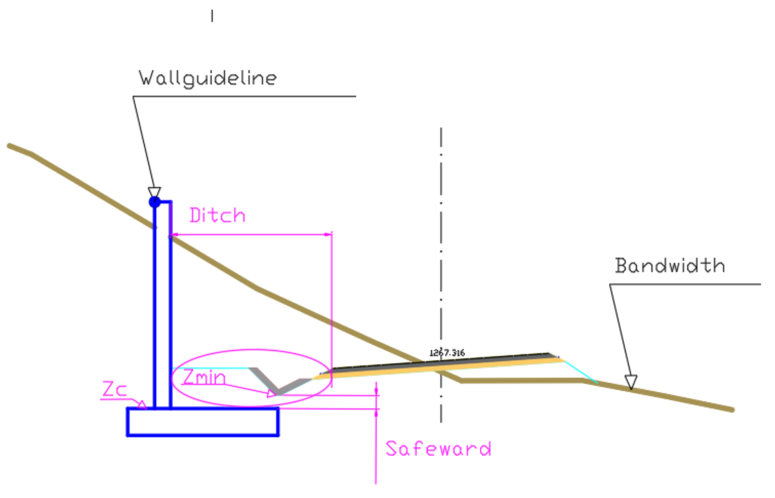
  • Modelling of the linear work: platform, ditches, slopes, walls, horizontal and vertical signs, and containment elements. In this phase, the BIM model is generated from the initial land surface and the linear work.
  • Export of the initial terrain and linear work as TIN (triangulated irregular network) files in a format capable of being interpreted by the structural calculation software.
  • Import of TINs into the structural calculation software. Three-dimensional modelling and calculation. In this phase, the BIM model of the structures is generated.
  • Association of the BIM models generated in the previous phases.

3.1. Initial Information Processing

In the first step, the initial data are entered from the cartography. This procedure can be completed in three different ways:
  • Vector model: vector models are based on entities, basically points and lines, defined by their coordinates [10].
  • Raster model: each figure corresponds to the average value of elementary units of non-zero surface area that tessellate the terrain with a regular (matrix) distribution, without overlapping and with total coverage of the area represented [10].
  • LIDAR model: a point cloud is a digital list of points with x, y, z coordinates and one or more descriptive attributes, including a point identifier. For more details see [11,12,13].
Once the cartographic information is available, we proceed to the design of the linear work.

3.2. Initial Design of the Linear Construction

The design of a linear work requires a sequence of processes [14] which are summarized below: the design of a horizontal alignment characterized by a succession of straight and curved alignments. Next, the cross-sectional profiles are obtained with a certain equidistance. The layout is designed on this profile, determined by a succession of straight alignments linked together by parabolic arcs. To complete the design, the cross-section needs to be defined, which contains information about the characteristics of the roadway: width of the lanes and auxiliary roads, the definition of the road surface, characterization of the cuttings and embankments, definition of the ditches according to the hydraulic conditions, etc.
Because of the previous design, the linear work may occupy a space that could be incompatible with the initial design criteria. This situation implies the need to introduce structural elements such as retaining walls, to reduce the occupation of the adjacent land since the clearing and/or embankment slopes are reduced. Reasons which can motivate the use of these elements include geotechnical conditions, visibility problems which require the placement of a clearing berm, etc. In any case, the need for retaining structures or walls requires a definition and correct relative geopositioning between the surface of the land and the designed platform.
The geometric definition of these retaining structures requires the definition of their horizontal alignment, the height of each of the sections of the previous polygon and the cross-section, which are described below. This section only refers to the intrinsic part of the interaction between containment structures and linear work.

Horizontal Alignment of the Structure

In general, there are two situations that should be differentiated. If the retaining structures are positioned in a straight section of the projected linear work, the horizontal alignment of the same is polygonal with a single alignment. However, when the structure to be designed is located in a curved section, its definition assumes a polygon with several straight alignments (see Figure 2).
The polygon that defines the position of the structure corresponds to the upper vertex in contact with the ground surface (Figure 2). The distance between the polygon which defines the direction of the wall and the axis of the road is determined by various factors: structural conditions which allow the geometric fit of the structure with respect to the platform [15], aspects related to visibility which will determine the minimum distance [16], geotechnical aspects [17,18], etc.
It can already be seen that the interaction between linear work and structure is an iterative process that will require several modifications until an optimum design is achieved, which means that there must be a fluid interchange between all the design phases, as well as between the software tools involved.
With the criteria established at this point, the alignment of the polygon is used to define the containment structure by means of computer-aided design software. The structure of the data file containing the polygon can be seen in Table 1. Once the linear work has been designed, with its containment structure, the following elements are available: initial land surface, surface of the designed linear work and the BIM model of the land-linear work complex.

3.3. Export of the Triangulated Irregular Network

Once the initial topographic surface and the designed linear work are defined, both surfaces are exported from the linear construction design software with a specific format that can be read by the structural calculation software. This aspect is crucial for the design of this type of work as it requires an iterative process until an acceptable design is obtained.
Over the last year (2019–2020), work has been carried out to facilitate interoperability between two software packages with very different characteristics. The ISTRAM computer application, dedicated to the design of linear works, and the CivileStudio structural calculation software, agreed to establish a common file structure for the exchange of information that would make it possible to import the initial terrain area as well as the designed work [19,20].
The first aspect to be considered is the cartographic format. As shown in Section 3.1, terrain modelling can be carried out in two ways: by the combination of data points into nets (triangulated irregular nets—TINs) or by a regular mesh or grid [21]. TINs provide a better representation of the geometry of the terrain by modifying the density of the network of triangles according to the changes in the surface [22]. The use of a grid for the representation of a medium or large size (>1 km) terrain model is not appropriate for the design of linear works since it generates poor definition in areas with abrupt changes of relief [23] or it requires a very small mesh size, which implies large files that make it difficult to handle.
De Wulf et al. [24], researched the suitability of each of the cartographic formats. They conclude that for terrain with very irregular geometry, the use of a TIN is recommended due to its greater capacity to adapt to the terrain. Bearing in mind that the methodology presented here should be capable of adapting to any type of terrain and furthermore that the platform of linear works incorporates singular elements such as ditches which are characterized by having high slopes, the TIN method is considered to be the most appropriate option.
Once the TIN option was chosen for the modelling of terrain surfaces and designed linear works, as it must have a certain format so that the structural calculation software is able to interpret it correctly. The format is described in Table 2. This data structure is identical to define both the original terrain surface and the platform of the projected linear work. Figure 3 displays an image corresponding to the TIN export options provided by the ISTRAM linear construction software package used in this work.
Figure 4 reveals a screenshot in the CivileStudio system once the initial surface and the designed platform are imported.

3.4. Modelling and Calculation of Earth Retaining Structures

The process begins with the introduction of a polygon representing the geometric location of the upper vertices in contact with the ground (transverse) (Figure 2). Table 1 shows the format that the polygon should have in order to be imported by the CivileStudio structural calculation software.
With the information provided from the terrain surface and the position of the structure, it is possible to obtain the heights of each one of the wall’s panels to be able to contain the terrain. In order to optimize the structure, so as to minimize the volume of concrete, the formwork surface and the amount of steel, the height of each of the sections in which the structure is discretized must be calculated. A greater height than necessary achieves the objective of containing the terrain but makes the design more expensive. On the other hand, an insufficient height does not achieve the objective of containing the terrain in its entirety and material falls onto the road, causing an increase in accidents and a higher cost of maintaining the road infrastructure.
In order to accurately and automatically determine the heights of each section of the structure, the CivileStudio structural calculation software contains an algorithm that calculates the intersection of the plane of each section of the wall with the TIN representing the ground surface. Therefore, the problem consists of solving a set of linear equations, Equations (1) and (2), whose solution is a set of straight lines—whose projection on the horizontal plane coincides with the initial polygon—representing the height of each section of wall.
Figure 5 reveals the set of planes containing the guideline of the wall and the intersection it produces with the TIN of the terrain (with each of the triangles that make up the terrain).
A R W j x + B R W j y + C R W j z + D R W j = 0
A T I N i x + B T I N i y + C T I N i z + D T I N i = 0
where RWj represents each of the j vertical planes contained in the initial polygon, TINi represents the i triangles of the TIN model corresponding to the surface of the initial terrain, DRWj and DTINi are the constants corresponding to the plane equation.
However, occasionally the number of sections of the initial polygonal wall is not only determined by the alignments in the plan, but there are other determining factors such as the geometry of the terrain. In Figure 6 it can be seen that when considering only the plan layout of the wall, four sections are necessary. However it is necessary to introduce three additional vertices (total of eight) to obtain seven sections and in this way the wall is capable of containing the terrain. Finally, it should be mentioned that the structural calculation software must have an option which allows the height of the crest of the wall to be raised a certain height in order to obtain a safety margin.
Regarding the geometric definition of the footing, it is necessary to determine the upper level of the wall footing, Zc, in order to provide shelter from the low points of the platform, Zmin, of the designed work. For these purposes, it is necessary to import the TIN model of the projected linear work. In Figure 7, the interaction between the wall footing and the platform is shown in a schematic way
The calculation of the guard is obtained by scanning a certain width that must be indicated in the structural calculation software, in which the minimum height of the platform, Zmin, is analyzed, to which the minimum guard is added at the designer’s discretion. From this height, the foundations of the structure will be located.
This workflow is valid for a footing with a constant (horizontal) top dimension for each of the panels. This hypothesis is ratified by the usual procedure in wall construction, where a sloping foundation makes formwork tasks substantially more difficult.
In this way, the location of the wall is defined in its entirety, making its position compatible with the terrain it must contain, as well as with the interaction of the platform of the projected linear work.

3.5. Structural Calculation of the Wall

Finally, the intrinsic parameters related to the calculation of structures, concrete, steel and the geotechnical characteristics of the terrain must be entered.
The CivileStudio structural calculation program used in this research obtains as final results the geometry and reinforcement plans, the measurements and the calculation reports. Within the calculation report, the program includes an analysis of the wall through the verification of the different limit states considered in accordance with the selected regulations: ground subsidence, sliding, overturning, global stability, bending breakage, shear breakage and cracking. With regard to the regulations, the software incorporates Spanish [25,26], European [27] y and American [28] regulations.

4. Case Study

This section applies the methodology set out in Section 3 on a mountain road located in the province of Teruel (Spain). The aim is to increase the width of the roadbed which currently has a total width of 5 m to 8 m: a 6 m roadway plus 1 m verges on each side. The layout is unique in that, as can be seen in Figure 8, there is a service road on the left side of the road which is to be widened, and on the right is the ravine of the Camarena River. With these conditions, it is necessary to build retaining walls that allow the optimization of the terrain, as well as the retaining structures which are to be built.

4.1. Obtaining the Model of the Current Terrain

The starting point is a base cartography taken in the field with a total station at 1:500 scale in vector format, from which a TIN surface is obtained and exported in IFC format, through the ISTRAM linear construction design software.

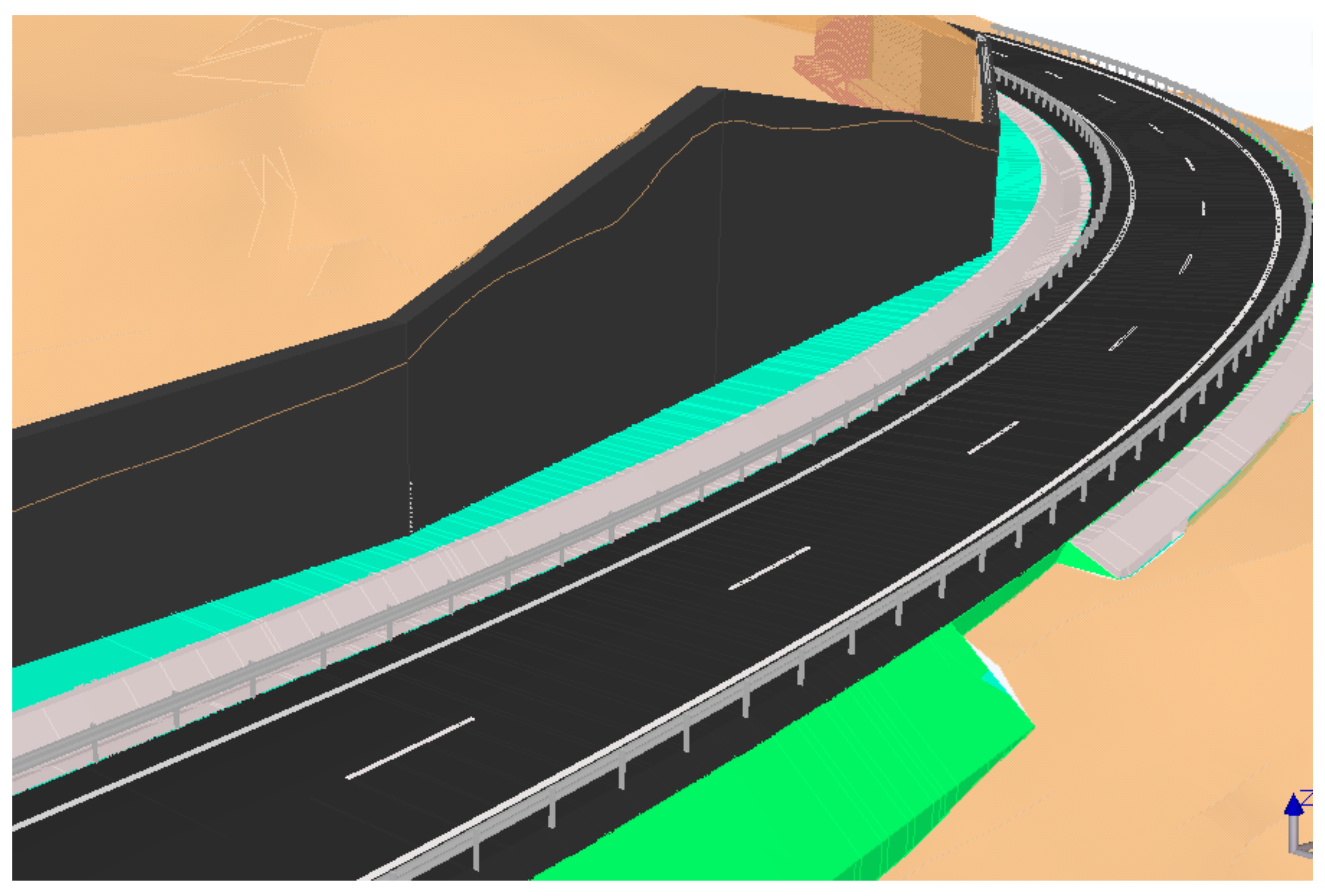
4.2. Obtaining the Linear Construction Model

In accordance with the methodology, a section of the road that is to be extended is then modelled. As the objective is the joint treatment of linear works and retaining structures, only the first 166 m are shown, coinciding with the need to build walls.
The characteristics of the new platform are indicated in Table 3.
With the characteristics indicated Table 3, the linear work is modelled using the ISTRAM linear construction design software, which allows the design to be carried out in accordance with the current Spanish regulations on road layouts [29], the result of which can be seen in Figure 9.
ISTRAM supports, once the linear work is modelled, exportation in the IFC format. Figure 10 displays the design of the linear work, with the holes for the location of the structures. The slopes of the left margin, next to the wall, were modelled vertically leaving space for the location of the retaining structures. This step is performed due to the fact that the form of collaborative work imposed by the BIM methodology consists of different agents working on a project with different tools that must interact with each other in a simple, fluid and safe manner to avoid conflicts between them.
Once the linear work is modelled, the structures are designed. For this, it is necessary to export the TIN surfaces of the initial terrain and the linear work.

4.3. Modelling of the Structure

Following the workflow indicated in the methodology, in this stage, the containment structures are modelled. The CivileStudio structural calculation software was used in this case due to its capacity for communication with the ISTRAM software. In accordance with Figure 1, the structural calculation software needs the information of the initial terrain and the linear work in the TIN format, as well as the location of the polygonal structure, and are entered using the format shown in Table 2.
This information makes it possible to establish coherence between both models (linear work and structure) so that the connection between the two can be guaranteed, then the rest of the parameters to finish the design of the structure must be entered. These parameters obey geotechnical and structural criteria. Figure 11 shows the interface for the introduction of data. There are three clearly differentiated sections: information referring to the footing, elevation and terrain. In the interfaces corresponding to the elevation and terrain, the tab that automatically calculates the data relating to the geometry of the terrain and the platform is highlighted in red (Figure 11).
Once the calculation is completed, the structural calculation software provides a calculation report, geometric definition drawings of the structure and reinforcements and generates a BIM model (IFC format), all in the same coordinate reference system as the linear model. This aspect is fundamental for the association of all models involved.
Figure 12 reveals the association of the three models: topography, linear work and structures. As a result of a correct design, the structures are high enough to contain the terrain. Figure 13 displays the connection between the top of the footing and the ditch, so that there is no interference between the foundations and the linear work.

5. Economic Analysis

The use of the BIM methodology generally results in better designs, but they also have economic consequences. Bryde and Broquetas [30] explored the benefits of this methodology by analyzing 35 construction projects, concluding that the most important benefits are those related to the economic aspect. However, there is no commonly accepted methodology [31,32,33] for quantifying economic benefits. Barlish and Sullivan [34] measured BIM implementation benefits by comparing BIM and non-BIM case studies. Ham and Moon [35] quantified the benefits by observing the number of errors made using the BIM approach versus the non-BIM strategies.
Considering the limited number of works that provide details about the economic impact on the different stages of a design project of the BIM methodology in a civil engineering context, a small size Spanish engineering firm agreed to serve as a testbed for the methodology presented in this paper. This firm has 30 employees, producing about 40 projects per year with a turnover around 1.4 million euro in the last exercises. Since 2002, this firm has implemented an accounting system called COGEST [36]. This system makes it possible to quantify the economic impact of each of the activities carried out in the company, as well as its differentiation between the different phases of the project.
Three types of projects (T1, T2 and T3) were selected for the analysis. For each type, a couple of projects with similar characteristics were selected. One developed with the new methodology and the other one with the classic method (non-integrated design tools not supporting an associated model). The cost system in this engineering firm is configured using the six phases in the definition of project presented in Table 4. Table 5 displays the reduction in costs for the engineering firm to develop the project considering only the first three phases in the project definition. The remaining phases are not considered because the impact of the new methodology is limited.
The selected projects for the comparison in applying the new methodology were carried out after staff in the firm gained sufficient experience to leverage the new methodology so that the results were not affected by the initial learning period of implementing a new methodology [37].
As can be seen in Table 4, in all cases, there is a significant cost reduction, with an average cost reduction of 45%. Type T3 represents a larger reduction since during the project development process, important modifications in the project requirements were required after several months of work. In these situations, the classical methodology means a complete rework, while the new methodology takes advantage of important reuse of part of the work previously completed.
Considering the phases for the development of a project in this firm and the percentage of costs related to each of them (Table 5), the phases that are directly involved with this methodology (phases 1, 2 and 3) account for 65% of the total cost. From these results, in an approximate way, it can be concluded that the average global reduction of cost using this new methodology is approximately 30% (the cost reduction is a 45% in the first three phases that represent a 65% of the overall cost).

6. Conclusions

Interoperability issues have an important economic impact on many design activities that are supported by computer-aided design tools. This situation has existed for many years in the civil engineering field due to the lack of means to support a true integration between the specialized software tools used in each step of the design process.
In this context, the first main contribution of this paper is a design methodology for linear works based on the association of BIM models created with different software tools that are linked using specific file formats conceived to solve the interoperability issues between these applications. Its integration provides many benefits, both from an economic and technical points of view. This positively impacts the sustainability aspects related to the use of human resources in the design phase and of materials during the execution phase, anticipating possible errors and deficiencies, which results in a better design. The precision in the definition and construction of this type of civil engineering works has considerable impact on the maintenance and conservation of the constructed road which is closely related to sustainability.
The second main contribution of this paper is the economic analysis of the implementation of the methodology, which is based on real data provided by an engineering firm that has implemented it. The granularity of the cost control system of this firm enables the study of the economic impact on the different stages of a design project of the proposed methodology.
It is important to mention that these results are framed within the typology of structures described in this article in the context of a small-sized engineering company in the civil engineering field.

Author Contributions

The authors confirm contribution to the paper as follows: Conceptualization, J.Á.A. and M.C.; Investigation, J.Á.A., N.M.-D., F.N. and J.C.-P.; Methodology, J.Á.A. and N.M.-D.; Supervision, M.C.; Visualization, F.N. and J.C.-P.; Writing—original draft, J.Á.A. and N.M.-D.; Writing—review and editing, F.N., J.C.-P. and M.C. All authors have read and agreed to the published version of the manuscript.

Funding

This research received no external funding.

Acknowledgments

The authors wish to acknowledge support from ISTRAM, CivileStudio and the engineering firm for the information provided.

Conflicts of Interest

The authors declare no conflict of interest.

References

  1. Dassisti, M.; Jardim-Goncalves, R.; Molina, A.; Noran, O.; Panetto, H.; Zdravković, M.M. Sustainability and interoperability: Two facets of the same gold medal. In OTM Confederated International Conferences “on the Move to Meaningful Internet Systems”; Springer: Berlin/Heidelberg, Germany, 2013; pp. 250–261. [Google Scholar]
  2. Cooperative Research Center for Construction Innovation. Adopting BIM for Facilities Management: Solutions for Managing the Sydney Opera House; Cooperative Research Center for Construction Innovation: Brisbane, Australia, 2007. [Google Scholar]
  3. Borrmann, A.; Beetz, J.; Koch, C.; Liebich, T.; Muhic, S. Industry Foundation Classes: A Standardized Data Model for the Vendor-Neutral Exchange of Digital Building Models. In Building Information Modeling; Springer International Publishing: Berlin/Heidelberg, Germany, 2018; pp. 81–126. [Google Scholar]
  4. O’Connor, A.C.; Dettbarn, J.L.; Gilday, L.T. Cost Analysis of Inadequate Interoperability in the US Capital Facilities Industry; National Institute of Standards and Technology (NIST): Gaithersburg, MA, USA, 2004. [Google Scholar]
  5. Grilo, A.; Jardim-Goncalves, R. Value proposition on interoperability of BIM and collaborative working environments. Autom. Constr. 2010, 19, 522–530. [Google Scholar] [CrossRef]
  6. Bernstein, H.; Jones, S.; Russo, M. Green BIM—How Building Information Modeling is contributing to green design and construction. J. Inf. Technol. Civ. Eng. Arch. 2015, 2, 20–36. [Google Scholar]
  7. Bynum, P.; Issa, R.R.A.; Olbina, S. Building information modeling in support of sustainable design and construction. J. Constr. Eng. Manag. 2013, 139, 24–34. [Google Scholar] [CrossRef]
  8. Geraci, A.; Katki, F.; McMonegal, L.; Meyer, B.; Lane, J.; Wilson, P.; Radatz, J.; Yee, M.; Porteous, H.; Springsteel, F. IEEE Standard Computer Dictionary: Compilation of IEEE Standard Computer Glossaries; IEEE Press: Piscataway Township, NJ, USA, 1991; ISBN 1559370793. [Google Scholar]
  9. BuildingSMART International. Available online: https://www.buildingsmart.org/ (accessed on 30 October 2020).
  10. Felicísimo, A. Modelos digitales del terreno: Introducción y aplicaciones a las ciencias ambientales. Oviedo Univ. Oviedo 1994, 118. Available online: http://www.etsimo.uniovi.es/~feli (accessed on 30 October 2020).
  11. Baltsavias, E.P. A comparison between photogrammetry and laser scanning. ISPRS J. Photogramm. Remote Sens. 1999, 54, 83–94. [Google Scholar] [CrossRef]
  12. Rutzinger, M.; Elberink, S.O.; Pu, S.; Vosselman, G. Automatic extraction of vertical walls from mobile and airborne laser scanning data. Int. Arch. Photogramm. Remote Sens. Spat. Inf. Sci. 2009, 38, 7–11. [Google Scholar]
  13. Zhao, H. Recognizing Features in Mobile Laser Scanning Point Clouds towards 3D High-Definition Road Maps for Autonomous Vehicles; University of Waterloo: Waterloo, ON, Canada, 2017. [Google Scholar]
  14. Hirpa, D.; Hare, W.; Lucet, Y.; Pushak, Y.; Tesfamariam, S. A bi-objective optimization framework for three-dimensional road alignment design. Transp. Res. Part C Emerg. Technol. 2016, 65, 61–78. [Google Scholar] [CrossRef] [Green Version]
  15. Yepes, V.; Alcala, J.; Perea, C.; González-Vidosa, F. A parametric study of optimum earth-retaining walls by simulated annealing. Eng. Struct. 2008, 30, 821–830. [Google Scholar] [CrossRef]
  16. Nehate, G.; Rys, M. 3D calculation of stopping-sight distance from GPS data. J. Transp. Eng. 2006, 132, 691–698. [Google Scholar] [CrossRef]
  17. Borga, M.; Tonelli, F.; Selleroni, J. A physically based model of the effects of forest roads on slope stability. Water Resour. Res. 2004, 40. [Google Scholar] [CrossRef] [Green Version]
  18. Vanmarcke, E.H. Reliability of earth slopes. J. Geotech. Eng. Div. 1977, 103, 1247–1265. [Google Scholar]
  19. Istram Software. 2020. Available online: https://www.istram.net (accessed on 30 October 2020).
  20. CivileStudio Software. 2020. Available online: https://www.civilestudio.com (accessed on 30 October 2020).
  21. Burrough, P.A.; McDonnell, R.; McDonnell, R.A.; Lloyd, C.D. Principles of Geographical Information Systems; Oxford University Press: Oxford, UK, 2015. [Google Scholar]
  22. Bates, P.D.; De Roo, A.P.J. A simple raster-based model for flood inundation simulation. J. Hydrol. 2000, 236, 54–77. [Google Scholar] [CrossRef]
  23. Bonham-Carter, G.F. Geographic Information Systems for Geosciences. Modeling with GIS. In Computer Methods in the Geosciences; Elsevier: Amsterdam, The Netherlands, 1996. [Google Scholar]
  24. De Wulf, A.; Constales, D.; Nuttens, T.; Stal, C. Grid models versus TIN: Geometric accuracy of multibeam data processing. In Proceedings of the Hydro12 Proceedings, Rotterdam, The Netherlands, 12–15 November 2012. [Google Scholar]
  25. CTE. DB-SE. Structural Safety: Foundations; Ministerio de Fomento: Madrid, Spain, 2007. [Google Scholar]
  26. EHE: Code of Structural Concrete; Ministerio de Fomento: Madrid, Spain, 2008.
  27. Frank, R. Designers’ Guide to EN 1997-1 Eurocode 7: Geotechnical Design-General Rules; Thomas Telford: Telford, UK, 2004; Volume 17. [Google Scholar]
  28. American Association of State Highway and Transportation Officials. Subcommittee on Bridges and Structures. In The Manual for Bridge Evaluation, 3rd ed.; American Association of State Highway and Transportation Officials: Washington, DC, USA, 2018. [Google Scholar]
  29. Instrucción 3.1 IC Trazado; Ministerio de Fomento: Madrid, Spain, 2016.
  30. Bryde, D.; Broquetas, M.; Volm, J.M. The project benefits of Building Information Modelling (BIM). Int. J. Proj. Manag. 2014, 31, 971–980. [Google Scholar] [CrossRef] [Green Version]
  31. Ghaffarianhoseini, A.; Tookey, J.; Ghaffarianhoseini, A.; Naismith, N.; Azhar, S.; Efimova, O.; Raahemifar, K. Building Information Modelling (BIM) uptake: Clear benefits, understanding its implementation, risks and challenges. Renew. Sustain. Energy Rev. 2017, 75, 1046–1053. [Google Scholar] [CrossRef]
  32. Love, P.E.D.; Matthews, J. The ‘how’ of benefits management for digital technology: From engineering to asset management. Autom. Constr. 2019, 107. [Google Scholar] [CrossRef]
  33. Shin, M.H.; Lee, H.K.; Kim, H.Y. Benefit-Cost analysis of Building Information Modeling (BIM) in a Railway Site. Sustainability 2018, 10, 4303. [Google Scholar] [CrossRef] [Green Version]
  34. Barlish, K.; Sullivan, K. How to measure the benefits of BIM—A case study approach. Autom. Constr. 2012, 24, 149–159. [Google Scholar] [CrossRef] [Green Version]
  35. Ham, N.; Moon, S.; Kim, J.H.; Kim, J.J. Economic analysis of design errors in BIM-based high-rise construction projects: Case study of Haeundae L project. J. Constr. Eng. Manag. 2018, 144. [Google Scholar] [CrossRef]
  36. Pellicer, E.; Pellicer, T.M.; Catalá, J. An integraed control system for SMEs in the construction industry. Rev. Constr. 2009, 8, 4–17. [Google Scholar]
  37. Hong, Y.; Hammad, A.W.A.; Akbarnezhad, A.; Arashpour, M. A neural network approach to predicting the net costs associated with BIM adoption. Autom. Constr. 2020, 119. [Google Scholar] [CrossRef]
Figure 1. Scheme for methodology.
Sustainability 12 09581 g001
Figure 2. Alignment of the wall axis (blue) with respect to the linear work.
Sustainability 12 09581 g002
Figure 3. ISTRAM export options for TINs.
Sustainability 12 09581 g003
Figure 4. Topographic surface (left) and platform surface designed in the linear works design software (right).
Sustainability 12 09581 g004
Figure 5. Intersection (red line) of the transverse planes (blue) with the TIN of the terrain (brown).
Sustainability 12 09581 g005
Figure 6. Interaction between floor and elevation to determine the number of sections that optimize the structure.
Sustainability 12 09581 g006
Figure 7. Relative position of the wall footing in relation to the linear work.
Sustainability 12 09581 g007
Figure 8. Location of the road to be extended (red) and existing road to be maintained (yellow).
Sustainability 12 09581 g008
Figure 9. Design of the linear work using the ISTRAM software.
Sustainability 12 09581 g009
Figure 10. Modelling of the linear work with the ISTRAM software.
Sustainability 12 09581 g010
Figure 11. Interface for data input to the CivileStudio structural calculation software.
Sustainability 12 09581 g011
Figure 12. Integration of the topography, linear work and structure.
Sustainability 12 09581 g012
Figure 13. Bottom view of the federated model including the reinforcements from the calculation.
Sustainability 12 09581 g013
Table 1. Format of the horizonal alignment of the projected structure.
Pointxy
1x1y1
2x2y2
nxnyn
Table 2. Structure of the TIN file generated by the linear construction design software.
Namexxxx
Idgggg
NNumber of vertices
1x1x1z1
Nxnynzn
MNumber of triangles
1v1v2v3
Mvmvmvm
Table 3. Characteristics of the new road.
Design ParameterValue
Total width8 m
No. of lanes2
Lane width3 m
Width of verges1 m
Berms1
Slope clearingVertical (walls)
Embankment slope3H:2V
Ditch width3 m
Ditch depth1 m
Surface35 cm
MBC10 cm
ZA25 cm
Table 4. Economic quantification as a percentage of each of the phases of a project.
PhaseEconomic Impact
1Conceptual design20%
2Calculations20%
3Geometrical definition25%
4Measurements10%
5Budget15%
6Printing, plotting and binding10%
Table 5. Comparison of the economic cost of the new methodology versus prior practices.
TypeReduction of Costs
T138%
T240%
T356%
Publisher’s Note: MDPI stays neutral with regard to jurisdictional claims in published maps and institutional affiliations.

