1. Introduction
Most of our current energy resources are based on fossil fuels. Due to the increasing trend in energy demand, there is an essential need for renewable and more sustainable sources of energy. One of the most significant energy-consuming sectors is transportation. In 2017, the transportation industry in the UK consumed energy equivalent to 56.5 million tons of oil, of which more than 97% was resourced from the oil industry [
1]. While this massive amount of energy is consumed, a considerable part of it is also wasted in different forms such as vibration and heat [
2,
3]. Zhao et al. investigated the potential energy from trucks for a road with 600 V/h of traffic in one lane and estimated that almost 150 kWh energy is produced by passing vehicles in 1 km of the road [
4]. This substantial energy is used to deform, vibrate and warm up the surface of the road and can be a good source for converting and harvesting it. Implementing energy harvesting technologies can turn these infrastructures into a source of energy.
A few methods are known to have the potential of harvesting energy from roads, which can be divided into two groups based on their resources, namely solar energy heat or solar radiation and kinetic energy (mechanical vibration), which includes electromagnetic and piezoelectric generating systems [
5,
6]. It is worth mentioning that most of these methods are categorised as micro energy harvesters, which generate energy at a small scale (a joule or less) [
5].
The focus of this paper is on the most significant energy-harvesting technologies. Considering that harvesting energy is about capturing, converting and storing it, these aspects are reviewed, with a focus on only field and experimental studies. Electromagnetic, piezoelectric and thermoelectric systems and solar panel implementation are discussed as the energy-converting units. Briefly, in electromagnetic converters, the mechanical displacement of the road pavements is used to spin an electromagnetic engine. Piezoelectric materials can convert mechanical vibrations to an electrical potential, thermoelectric materials give out electrical voltage once there is a temperature gradient in their bodies, and solar panels are well-known for converting solar radiation to electrical energy. All of these concepts have real-life applications as well. The “Magic Carpet” by MIT Media Laboratory and NASA’s deep space voyager are well-known practical examples of piezoelectric and thermoelectric harvesters, respectively [
7,
8]. Electromagnetic generators also have several applications, such as in wind turbines [
9].
This paper is a review of the formerly conducted research works in this field. In the following section, the concepts of different energy conversion systems are explained briefly. Afterwards, an overview of the recent studies of piezoelectric harvesters with different geometries are reviewed, which is followed by a summary of the new works and developments in thermoelectric harvesters, and electromagnetic systems are subsequently presented. Finally, recent advances in energy storage methods are outlined, and the last section summarises the main points of this paper and presents suggestions for future studies in the field.
2. Road Energy Harvesting Systems: Concepts and Experimental Studies
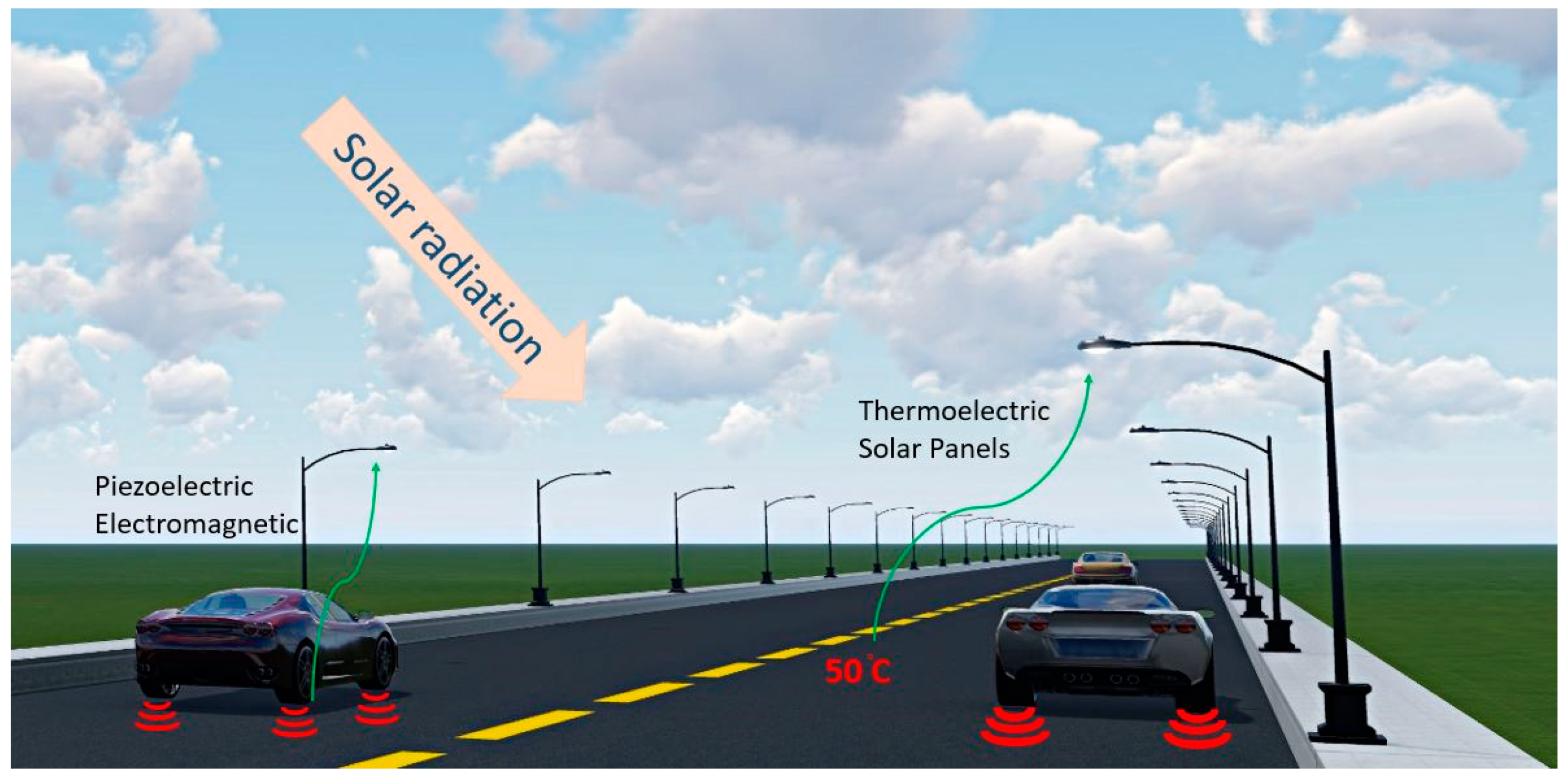
The available energy sources in roads are vibrations (mechanical) caused by passing vehicles, solar radiation on the large surface of the road and the temperature gradient (thermal energy) between the hot surface and colder bottom layers, induced by passing vehicles and solar radiation on the surface [
5]. Therefore, piezoelectric, electromagnetic, thermoelectric and solar panel systems are suitable for converting these forms of energy into electrical potential.
Figure 1 is a diagram showing the possible energy conversion in roads.
2.1. Piezoelectric Harvesters
2.1.1. Piezoelectricity
Piezoelectricity is the fundamental feature of piezoelectric materials. There are two types of piezoelectricity. Direct piezoelectricity is the conversion of mechanical vibrations to electrical potential, and inverse piezoelectricity is the conversion of electrical potential to mechanical vibrations. One of the famous and everyday functions of piezoelectric materials is in quartz watches. Piezoelectric materials can be either natural or synthesised, and once they are subjected to stress, electrical charge occurs through them (piezoelectricity) [
10]. To describe the state of a piezoelectric material, e.g., measure the voltage output under vibration or the strain under applied voltage, the constitutional law of piezoelectric materials, according to Equation (1), is followed.
In Equation (1), ε is the strain vector (m/m), D is the electric displacement vector (C/m
2), referring to the displacement of the dipoles caused by an electric field, and S
E denotes the compliance matrix constants in an electric field (m
2/N). Piezoelectric strain matrix is d (m/V), and ε
σ is the matrix of electric permittivity constants (F/m) at constant stress, which indicates the polarizability of a dielectric material. Stress vector (N/m
2) is σ, and E stands for the vector of the applied electric field (V/m).
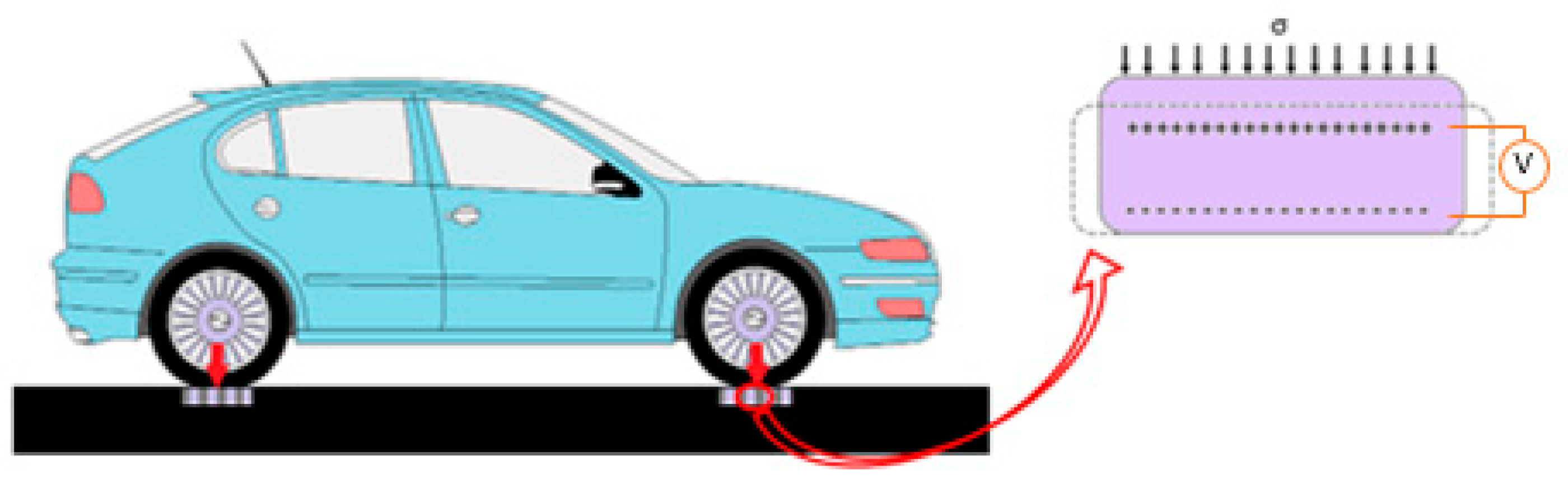
Figure 2 illustrates the concept of direct piezoelectric conversion within the context of road application.
The essential properties of these materials are the piezoelectric charge constant (d) and permittivity (ε). The former indicates the created polarisation under unit mechanical stress, and the latter is the polarizability of charges under stress per unit electrical field. Figure of merit (FOM) is a quantity defined to evaluate and optimise the performance of these materials. A number of figures of merit exist for piezoelectric materials, depending on their application and loading conditions. For energy harvesting purposes, the electromechanical coupling factor is one of the assessment factors utilised for the materials under equal mechanical energy:
Another figure of merit is defined for the materials under equal mechanical stress:
where d is the piezoelectric charge constant, E is the Young’s modulus and ε is the dielectric permittivity.
High performing synthetic piezoelectric materials for energy harvesting functions are PZT (lead zirconate titanate), PZN-PT (lead zinc niobate-lead titanate) and PMN-PT (lead magnesium niobate-lead titanate.). Examples of typical piezoelectric harvesters are cantilever beams, disks, cylinders and stacks [
11,
12,
13,
14,
15,
16,
17].
In addition to the materials’ properties, environmental properties, such as loading conditions and temperature, affect the output of piezoelectric harvesters. Their output becomes higher if the applied stresses are parallel to the polarisation direction. Loading frequency also significantly influences the output, and, regarding the temperature, the Curie point is the threshold temperature beyond which the material loses its piezoelectricity [
12,
18,
19,
20].
2.1.2. Experimental Studies on Road Piezoelectric Energy Harvesters
Energy generation from piezoelectric materials has been studied for a long time, almost since their discovery in the late 19th century. However, one of the recently focused fields is the applicability of this technology on roads in order to harvest energy. In this regard, roads’ loading conditions are the controlling condition to test the harvester, i.e., the amount of load should be limited to vehicles’ load, the frequency is related to the average speed of the vehicles, and the damping properties of the pavement material should be considered. The magnitude of the load is usually between 25 KPa and 0.7 MPa in different references (depending on the passing vehicle), and the frequency is 30 Hz or less [
21,
22,
23].
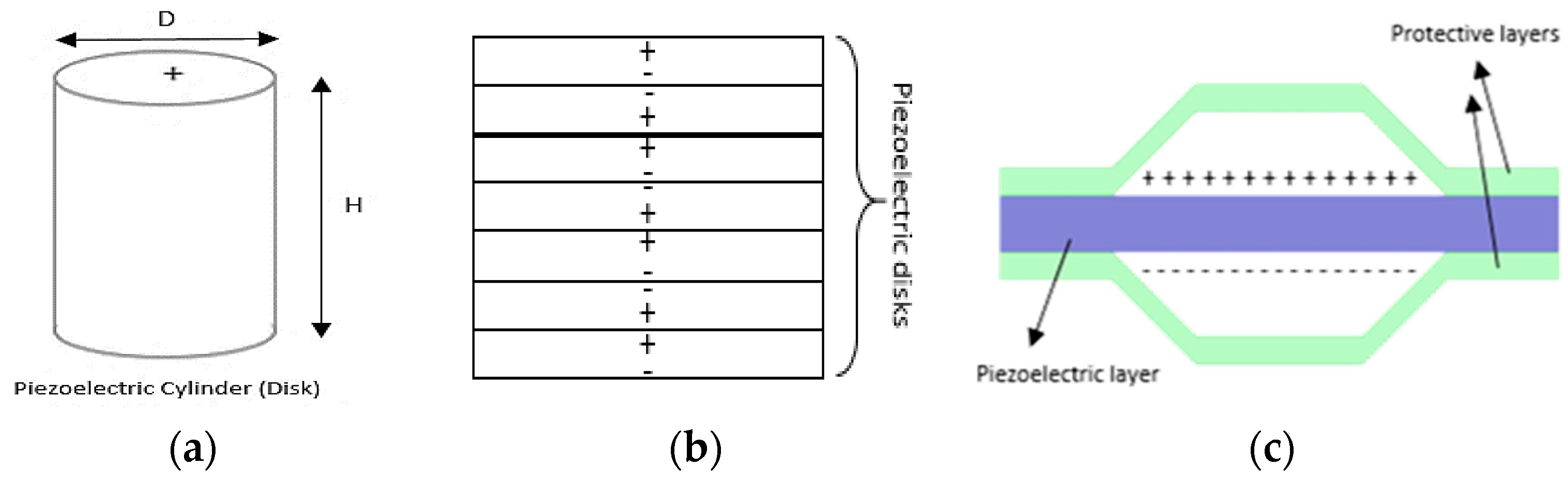
Figure 3 illustrates the shapes of four piezoelectric transducers used in roads.
Each of these transducers has a different level of mechanical strength based on its geometry and materials. For practical purposes, these transducers are placed in designated boxes or other protective structures. Cymbal, cantilever and hybrid systems are the other forms of piezoelectric transducers.
Bridge and Cymbal Piezoelectric Road Harvesters
Bridge piezoelectric harvesters have been the focus of several research works. As shown in
Figure 3, in these modules, a rectangular piezoelectric element is placed between two protective caps in the top and bottom.
Zhao et al. investigated three different bridge transducers through simulation and experiments with trapezoidal and arc-shaped caps. It was found that arch bridge transducers are capable of producing potential of almost 285 Volts under 0.7 MPa pressure and 10 HZ frequency. It is also shown that the modulus of elasticity and the thickness of the cap material is significantly effective on the output. At the same modulus of elasticity, increasing the thickness of the cap from 0.3 to 0.5 mm decreases the voltage by almost 9%. A higher modulus of elasticity results in a steady decrease in the output voltage. Regarding the compressive strength, the trapezoidal bridge performed better than arc-shaped caps and could withstand up to 1 MPa pressure [
23].
In another study, bridge transducers were fabricated by attaching horizontally polled piezoelectric rods together, using a silver paste to form a bridge transducer. Eventually, one harvester unit containing 64 modules of transducers was tested. Experimental results showed that, under a load of 0.7 MP at 5 Hz, 26 to 31 mWatt power was harvested [
3].
Cymbal transducers are similar to a cymbal in shape, holding a piezoelectric layer in the middle. Palosaari et al. designed and studied the potential of cymbal piezoelectric harvesters under low-frequency compressive forces. The results indicated that, under a frequency of 1.19 HZ, the cymbal with a 250 μm cap had the optimal performance, with an output voltage of almost 47 V under 24.8 N (approximately 25.8 KPa) [
24]. Another recent study on cymbal harvesters investigated their performance under frequencies lower than 30 HZ. An open circuit (OC) power output of almost 0.2 mW was obtained from the harvester under 500 N and 20 HZ. Moreover, in OC conditions, the voltage output would not change remarkably by frequencies of more than 20 HZ (almost 52 V) [
22,
25].
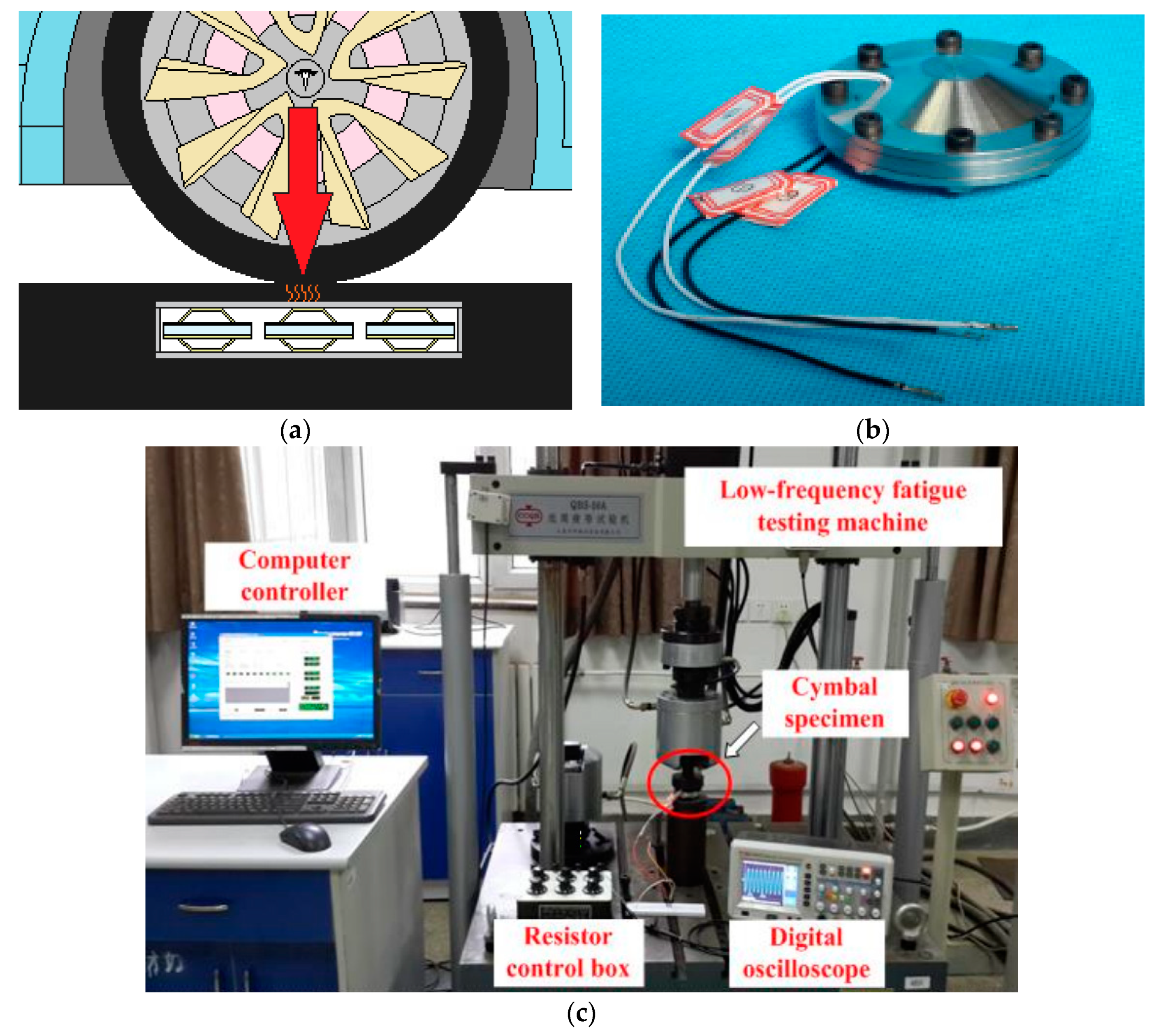
Figure 4 shows one example of embedding a bridge energy harvester in the road.
Disk and Cylinder Piezoelectric Road Harvesters
Roshani et al., in 2016, designed and tested piezoelectric disk harvesters and found that increasing the frequency and applied load has a positive effect on the harvester’s power output. A durability test on the harvesters showed a constant output in 8 h, and the feasibility study of the harvesters indicated that interstate highways with high traffic load are suitable alternatives for installing these harvesters [
26].
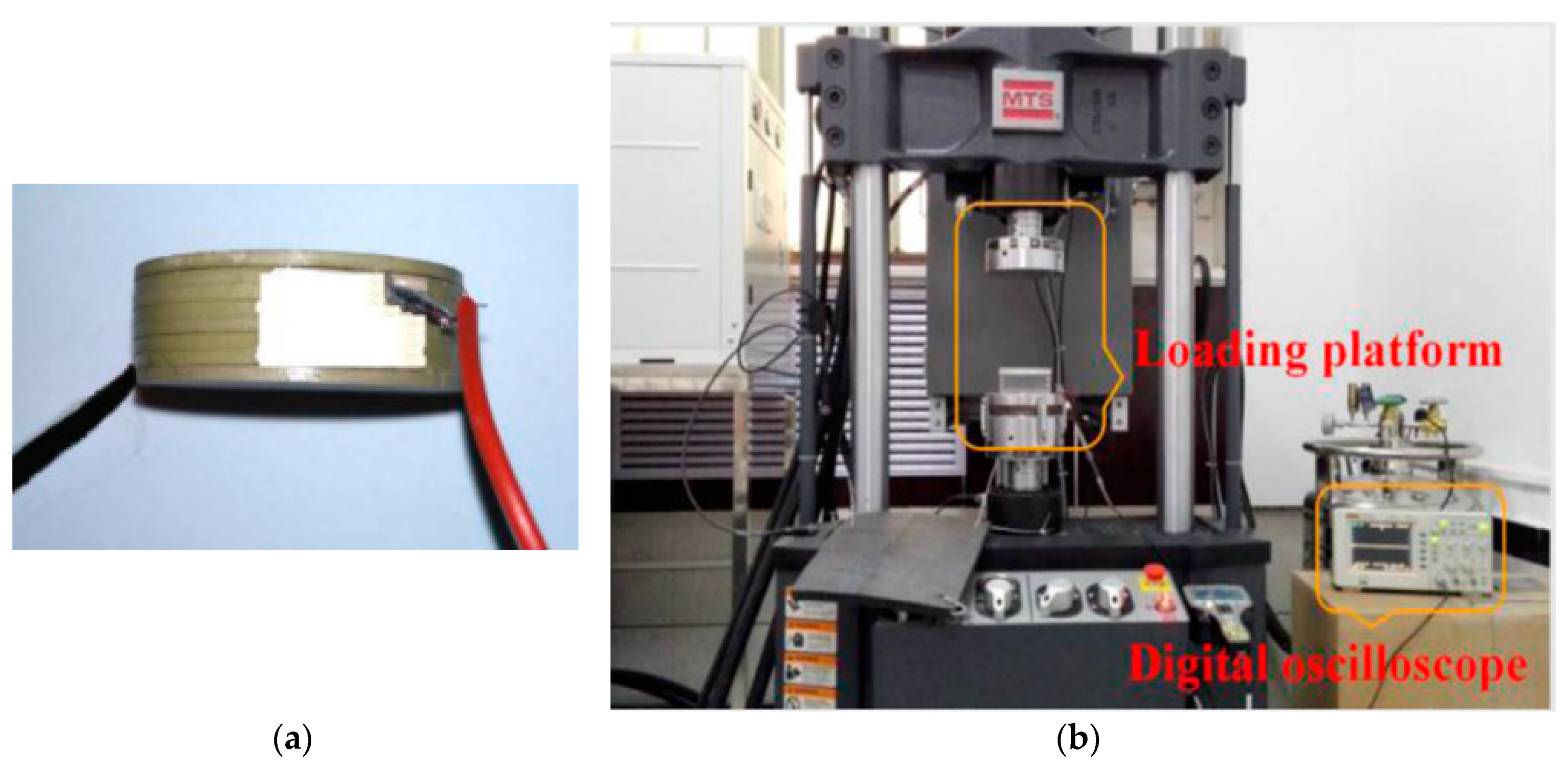
Figure 5 shows the disk harvester embedded in the asphalt sample being tested.
In another study, Xiong et al. fabricated harvester modules consisting of piezoelectric disks. It was found that the power output is highly related to the total axle loading of the vehicles. The average power output was almost 3 mW, which is enough to power small electronic devices embedded in the road [
27].
In a comparative study, several shapes of piezoelectric transducers were investigated theoretically by Zhao et al. It was found that piles and multi-layered piezoelectric transducers have higher conversion capability. Furthermore, in a theoretical optimisation study, it was suggested that a number of 8 to 16 cylindrical piezoelectric piles in each 0.04 m
2 of pavement are required in order to have a considerable energy outcome [
4,
28].
Stack Piezoelectric and Other Systems of Road Harvesters
There are also several studies on stack piezoelectric harvesters [
30,
31]. In 2014, Jiang et al. studied the potentials of such harvesters through simulation and experiments. Thirty-six layers of piezoelectric transducers were connected as one module and tested under three different compressive loads and four different frequencies. The highest power output of 0.2 W was obtained from 1360 N, under 6HZ frequency and almost 300 KΩ resistive load. The same loading scenario leads to an output of 0.05 mW in OC conditions [
32].
Stack piezoelectric harvesters were the focus of another study done by Khalili et al. which simulated a piezoelectric harvester, and the power output from the stack harvester matched the experimental data. The harvester was investigated under dynamic loads from 1.1 to 11 KN and frequencies ranging from 2.5 to 62 Hz. Based on the characterisation results, it was estimated that the power output peak of 1.5 Watts could be obtained at 11 kN load, 62 HZ and 500 KΩ resistive load [
25].
In another study, various piezoelectric stack harvesters were built and compared for their design process and performance. Two different fabrication methods were employed to build the stack harvesters. Both harvesters were tested under 0.7 MPa and 10 HZ cyclic load. It was observed that the harvester built by the multilayer adhesive process had a higher power output level of 32.4 mW, with an optimal resistance load of 30 kΩ. In comparison, the harvester made through the process of monolithic co-firing had a lower power output, of 9.6 mW, with an optimal resistance load of 20 kΩ. The power output of the system in the OC condition was attuned to 3.30 mW [
33].
In another study, Guo et al. in 2018 focused on the shapes of the harvesters and the filling materials (insulator) in the pavement. The cross-section of the road was divided into three layers: two layers of conductive asphalt and, in between, a piezoelectric layer, which was analysed with different shapes of piezoelectric curved roofs, balls and cylinders. The stiffness of the filler material in the piezoelectric layer was seen to be a critical factor in the output. In the fillers with low stiffness, piezoelectric balls had higher voltage output than the others, while, by increasing the stiffness, the voltage output decreased remarkably, by almost 100%. Given that the piezoelectric layers were modelled as a layer filled with discrete piezoelectric elements, the output was significantly different dependent on the stress distribution [
2].
Hybrid energy harvesters containing piezoelectric harvesters were also the focus of a study conducted by Fan et al., coupling electromagnetic and piezoelectric harvester units together to generate power at low frequencies. The results showed that, under hand-shaking vibrations, enough power was generated to illuminate light emitting diodes (LEDs). However, a larger portion of this power was generated by the electromagnetic harvester [
34].
Figure 6 shows a module of a stack piezoelectric road harvester.
Piezoelectric Cementitious Composites
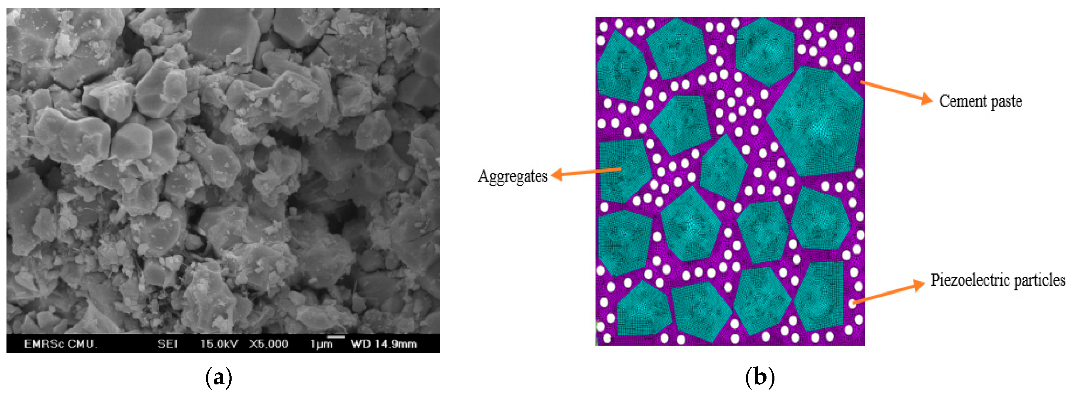
In addition to the design and fabrication of the conventional piezoelectric harvester units, another area of interest is developing cementitious piezoelectric harvesters, ideally to serve both as construction material and energy harvester simultaneously. These composites are made by mixing piezoelectric ceramic particles (mostly PZT) as additives to cement, polarising the mixes or both. So far, these studies have been conducted at the laboratory level, and no field tests have been reported.
In one study, piezoelectric cement composites were made by mixing PZT particles in cement by 30 to 90%, resulting in a significant increase in dielectric and piezoelectric properties compared to the plain cement mixes. The features remarkably improved by increasing the volume of PZT. Relative dielectric constant and piezoelectric constant (ε
r and d
33) increased from 79 and 0 in the plain mix to almost 300 and 45 pC/N in the sample with 90% PZT addition, respectively [
35]. The same researcher investigated the effect of PZT particle size distribution on the resulting composite by mixing three different PZTs with different average particle sizes. Larger PZT particles were found to be more effective in the overall improvement of the piezoelectric properties of the composites, which was due to the smaller contacting surface area between cement and PZT particles [
36].
Similarly, Sladek et al. developed a numerical method to predict the piezoelectricity of cement-PZT composites through the finite element method. The predictability of the method was compared to the previous experiments, showing good agreement between the results and also a remarkable increase in d
33 by adding more PZT particles [
37].
One of the challenges associated with PZT-cement composites is their complicated poling process, which needs high-temperature treatment. This challenge has been addressed in research by Gong et al., who mixed carbon nanotubes (CNTs) in PZT-cement composites to enhance the conductivity and simplify the polarisation process. According to the results, the addition of CNTs by up to 1.3% enabled polarisation at room temperature. Improvement in piezoelectricity properties happened with an optimum volume percentage of 0.3% [
38].
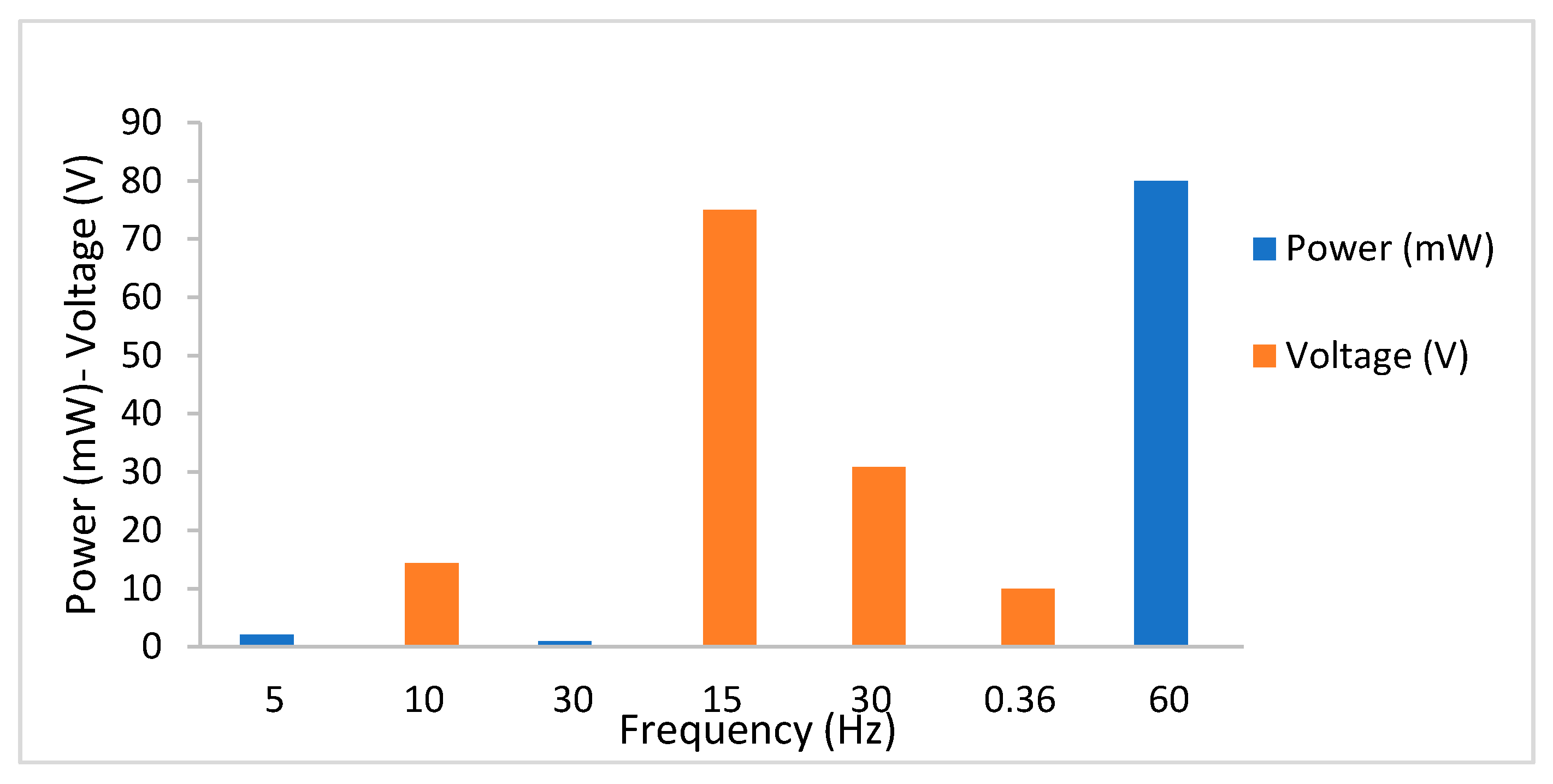
One of the crucial limitations of piezoelectric harvesters is the low power outcome. It can be summarised that piezoelectric harvesters, independent of their configuration and material properties, still have an outcome of almost 200 microwatts to 30 milliwatts [
6,
20,
27,
39,
40].
Figure 7 illustrates the internal structure of a cementitious piezoelectric composite.
It is noteworthy that the experimental studies’ power outputs of the road piezoelectric harvesters are all within the range of milliwatts. To provide an overview,
Figure 8 shows the power or voltage output of some of the highlighted studies.
2.2. Thermoelectric Harvesters
2.2.1. Thermoelectricity
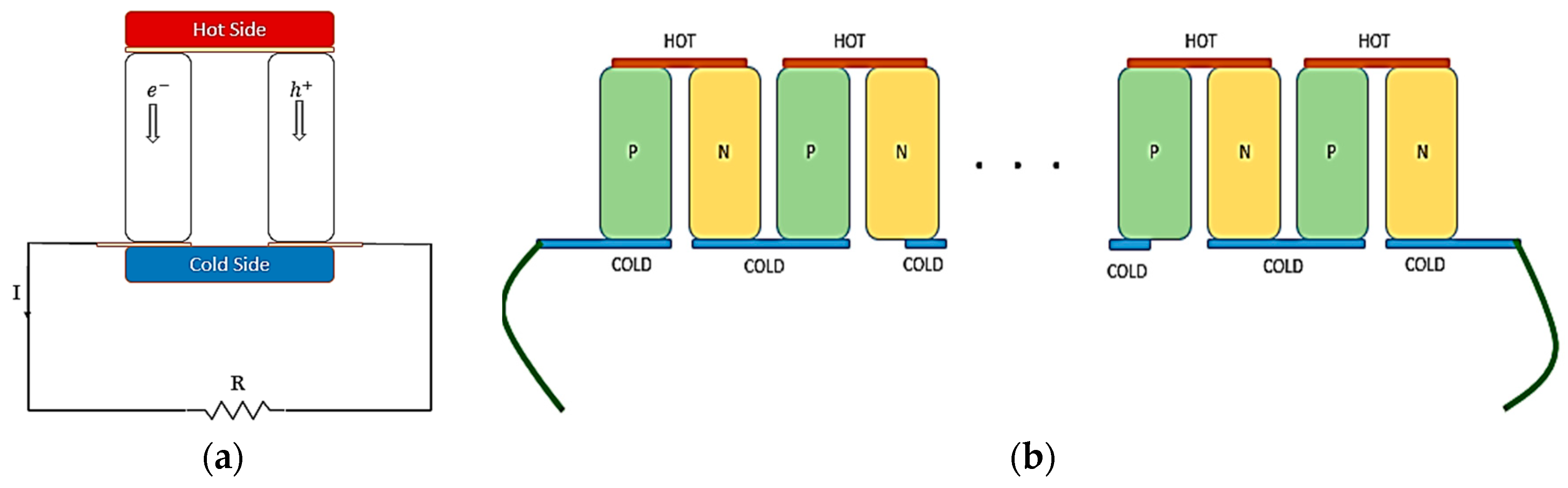
Thermoelectricity is the fundamental property of thermoelectric materials, which convert the temperature difference to electrical voltage. The Seebeck effect, named after the German scientist, is associated with thermoelectric materials and indicates the generation of the electrical voltage across the temperature gradient between the sides of a thermoelectric material. In these materials, heat carriers are charged particles, which can be electrons in n-type or holes in p-type thermoelectrics.
Figure 9 shows a power generating p-n thermoelectric setup. Thermoelectric generators have a use in temperature controllers.
Subsequently, thermoelectric harvesters depend on the temperature difference between their two sides, making the electrical charges (heat carriers) displace from one side to another and create electrical potential (Seebeck effect). This phenomenon, together with the Peltier effect and Thomson effect, are “thermoelectric effects” [
45,
46,
47].
The Seebeck coefficient is the fundamental property of the thermoelectric materials, which is the ratio of change in the generated voltage by temperature.
where ΔV is the change in the electrical potential and ΔT is the change in temperature. The performance of thermoelectrics depends on their Seebeck coefficient, electrical conductivity and thermal conductivity, as well as their environmental conditions, i.e., temperature difference between the sides. Similar to the piezoelectric materials, a dimensionless figure of merit is also defined for thermoelectric conductors, which is calculated according to the following formula:
Another assessment variable for thermoelectricity is the power factor:
In Equations (5) and (6), ZT is the dimensionless figure of merit, PF is power factor, S is the Seebeck coefficient of the matter (V/K), σ is the electrical conductivity (1/Ω·m), T is the temperature difference (K), and K is the thermal conductivity (W/m·K). Unlike the power factor, which is related only to the electronic features, ZT also depends on the thermal conductivity and the temperature difference.
Most of the thermoelectric materials, such as bismuth telluride and lead selenide, are synthetic. However, there are also claims of naturally occurring ones, such as zinc tetrahedrite [
13,
45,
46,
48,
49].
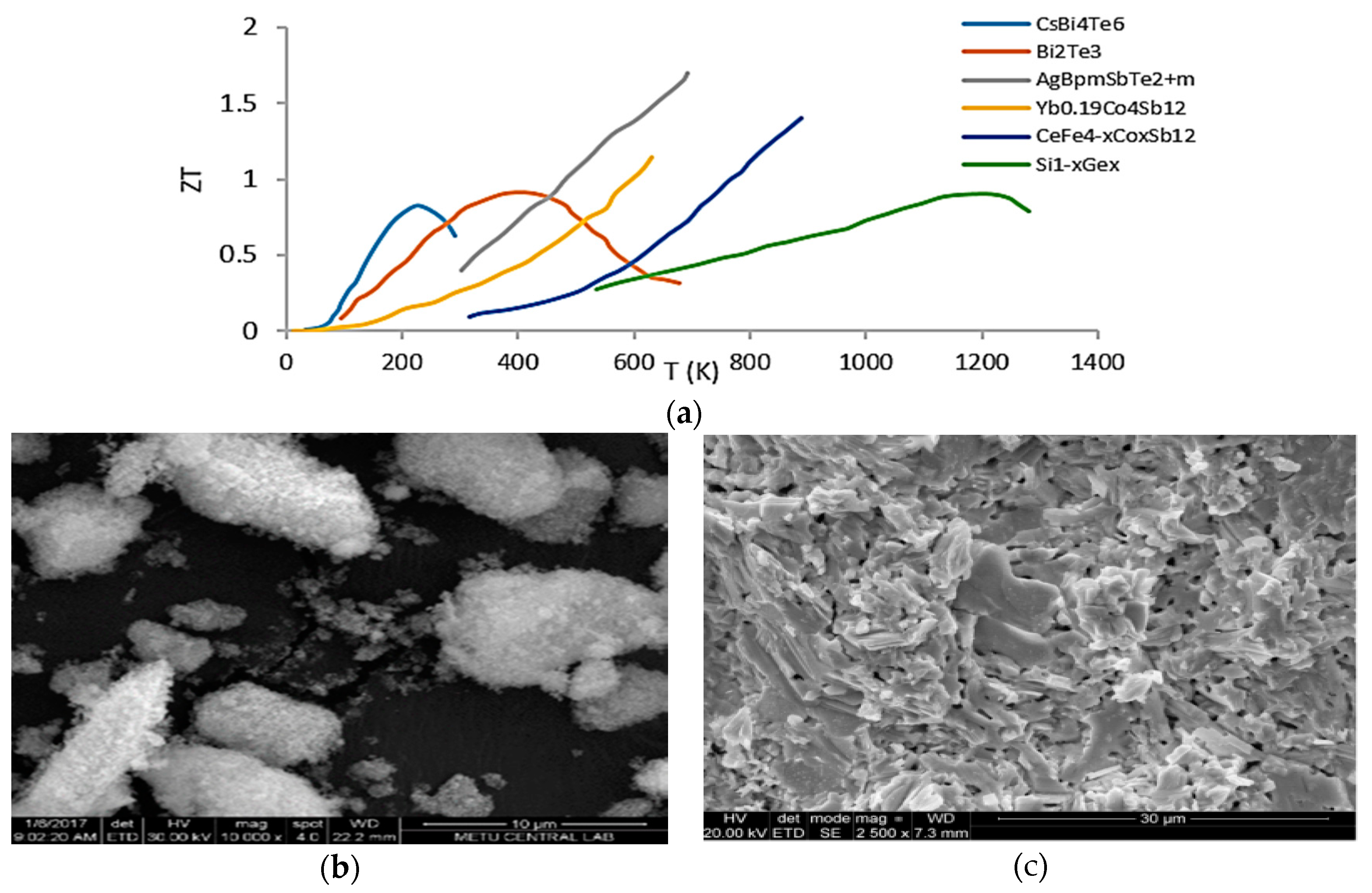
Figure 10a shows the change in the famous thermoelectric materials’ figure of merit by temperature.
According to
Figure 10, most thermoelectric materials have a high figure of merit at temperatures much higher than room temperature (almost 300–320 K) and the only ones performing in room temperature are CsBi4Te6, Bi2Te3 and Yb0.15Co4Sb12.
High electrical conductivity, which is critical for charge transfer within the material, and low thermal conductivity for maintaining the temperature difference over a more extended period are the other two crucial and favourable properties of thermoelectric materials.
2.2.2. Experimental Studies on Road Thermoelectric Energy Harvesters
Using Ceramic Thermoelectric Generator (TEG)
Road pavements have large surfaces, which are exposed to sunlight during the day. The combination of sunlight radiation and friction from passing vehicles can create a hot surface, especially in warm seasons. However, the temperature decreases gradually according to the depth of the road, creating a temperature gradient. In some areas, a gradient of 35 degrees has been measured along 23 cm of road profile depth, such as that detected on 5 consecutive days in San Antonio, Texas [
52]. In addition to the temperature gradient provided by the pavement, in some works, a pipeline system or storage has been constructed in the pavement in order to provide and maintain the gradient and transfer it to the thermoelectric modules [
6,
53,
54,
55,
56].
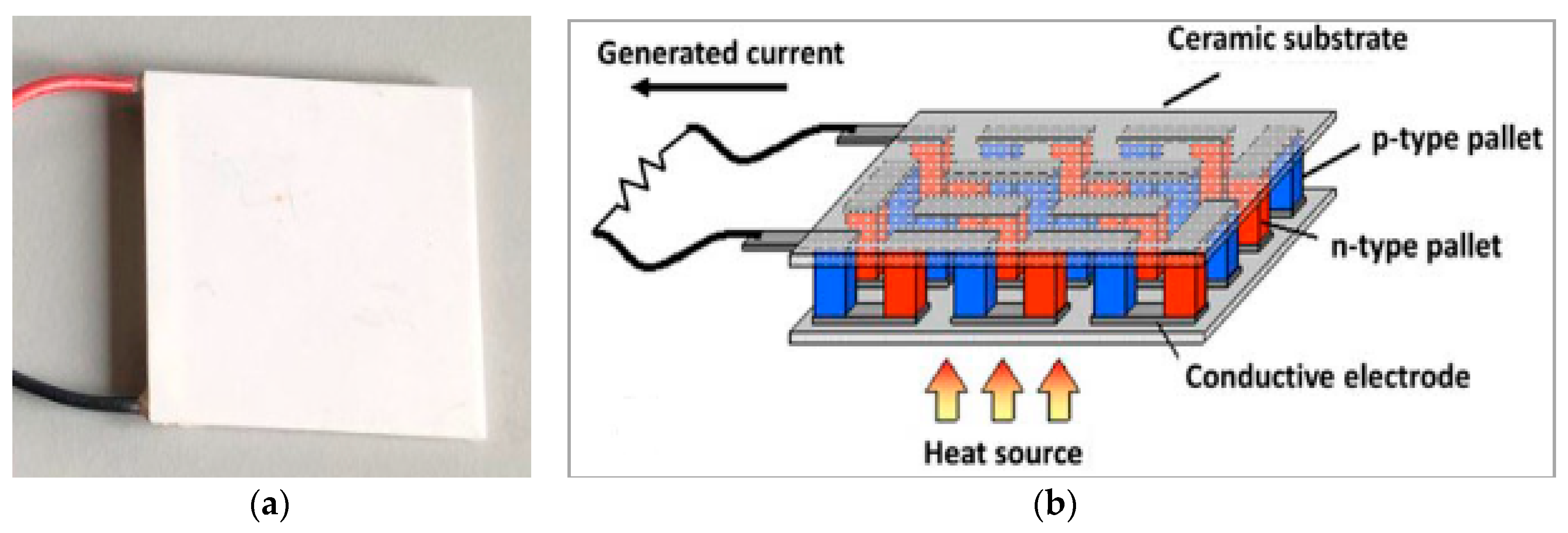
The converter unit of these systems is a ceramic TEG.
Figure 11 shows an example of a TEG. They are comprised of p-type and n-type thermoelectric junctions connected in parallel thermally and in series electrically (multiple junctions connected, similar to
Figure 9).
Park et al., in 2016, focused on the low energy output and the key factors affecting the output of thermoelectric harvesters on roads. A harvester module was developed using a TEG sandwiched between two conductive plates, which were connected to hot and cold sources separately. The performance of the designed harvester could be improved by matching their thermal and electrical impedances and reducing the heat loss between the heat exchange and the environment [
57].
Concrete structures in the road were the focus of another study by Lee et al. Laboratory experiments were conducted using a halogen lamp on a concrete block, simulating sunlight radiation on a concrete road barrier. The effect of the surface material was studied by measuring the voltage on two different surfaces of wood and aluminium (1000 times more thermally conductive than wood), placed on the concrete block. It was found that the output voltage was 1.5 times higher on the aluminium surface than the wooden one [
47].
Tahami et al. designed and tested a novel thermoelectric harvester, embedded in the pavement and thermally attached to the surface. The hot side of the ceramic thermoelectric module was connected with an L-shaped piece to the surface to transfer the heat, and the cold side was connected to a heat sink made of aluminium, holding a phase change material. Maximum power of 34 mW was harvested at 32 K temperature difference [
52].
Hasebe et al. developed a pavement cooling system with a thermoelectric generator, using an integrated pipeline system in the pavement as the heat collector and river water transfer as the cooler side, both connected to the layer of ceramic thermoelectric harvesters. Results of simulation and experiments showed that the highest power was harvested at 30 Ω and there was a temperature difference of 40.5 K between the hot and cold sides [
53].
In another study, a thermoelectric module was connected to the hot surface by a Z-shaped piece, and its cold side was connected to a heat sink filled with water. Two different configurations of modules were built, a two-TEG and a four-TEG prototype (each with different sizes). It was observed that the two-TEG prototype (larger total surface area) and the four-TEG (smaller surface area) gave 8 mW and 11 mW on average over the testing period. Field test results showed that the power output of the harvesters peaked in May, although the maximum temperature gradient occurred in June and July [
55].
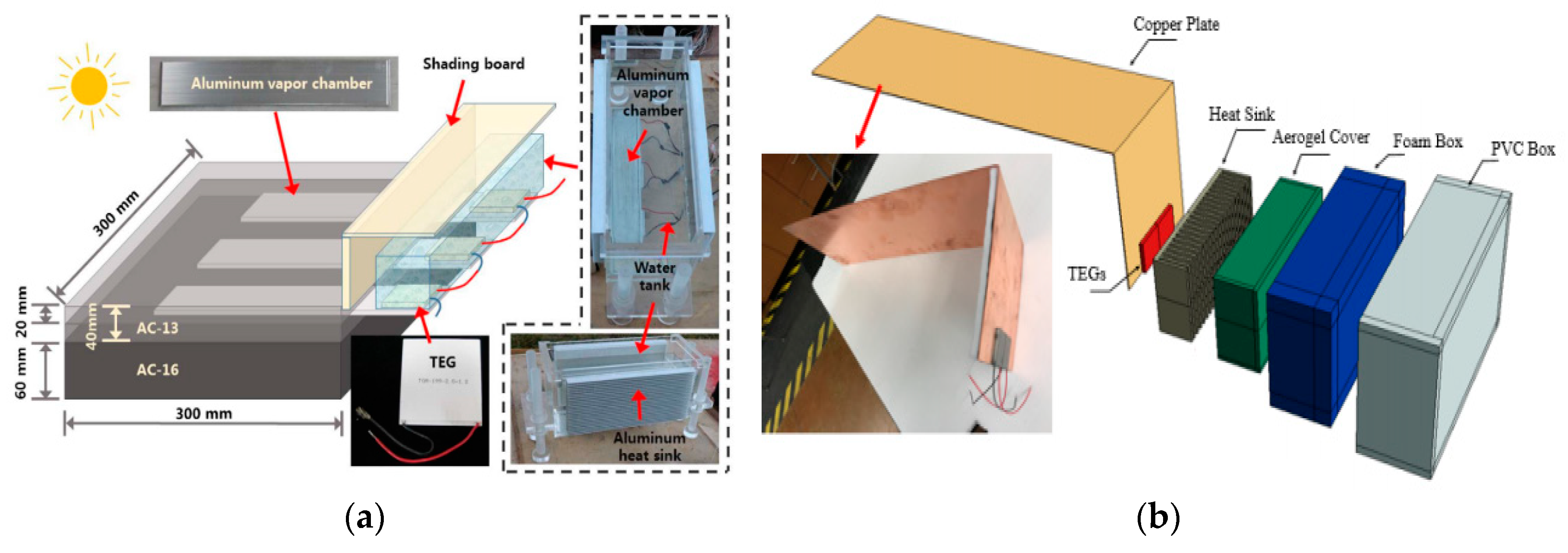
Thermoelectric generators were also employed to develop a harvesting system by Jiang et al. The system was comprised of a water tank as the cooling side and attached to one of the TEGs. The hot side of the TEG was attached to the hot pavement surface via an aluminium vapour chamber. The water tank was placed under a shading box. Small scale experiments showed that the generated voltages in indoor and outdoor tests were 0.73 V and 0.41 V, respectively; however, on larger scales, this output was reduced [
54,
58].
Figure 12 shows some applications of TEGs on road pavements.
Thermoelectric Cementitious Mixes
In addition to assembling the thermoelectric harvesters by TEGs, another recently developed approach utilises the thermoelectric properties of the cementitious materials and develops cementitious thermoelectric mixes, capable of generating power as well as being a construction material. Similar to piezoelectric mixes, the focus of these works is on building cementitious composite mixtures with known thermoelectric materials, for example, ordinary Portland cement and metallic oxides or carbon fibres and evaluating their thermoelectric properties and potentials. Several of these additives have been studied for their thermoelectric properties [
49,
59,
60].
Enhancement of the thermoelectric properties of cement composites with ZnO and Fe
2O
3 nanoparticles was studied by Tao et al. in 2018 [
61]. Cement composite paste samples were made by adding the nanoparticles in various percentages, characterising and testing them for their thermal and electrical conductivity and Seebeck coefficients. It was observed that by adding 1 to 5% of these nano-powders, the Seebeck coefficient and electrical properties of the mixes improved significantly. A similar observation was made by Ghahari [
62].
In an earlier study, cement composites with carbon nanotubes (CNTs) and fibres were also studied by Zuo et al. In addition to the thermoelectric properties and characterisation, they also studied the mechanical features. It was realised that the addition of a small percentage of carbon nanotubes improves the mechanical properties and changes the conventional cement paste into a P-type thermoelectric mix. By having a composite with 0.5% of CNTs, the Seebeck coefficient reached a maximum of 23.5 µVK
−1 [
63]. A similar observation was made by Tzounis et al., who studied cement composites with both p- and n-doped carbon nanotubes. The moisture content of the samples also affected their properties [
64].
Composites of carbon fibre and carbon fibre powder in cement have also been studied in some investigations. It was found that the charge density and mobility is affected by the amorphous structure of the composites, which is influenced by the percentage of carbon fibre addition. Addition of 1% carbon fibres to the cement paste mix was found to maximise the figure of merit of the samples (equal to 1.334 × 10
−7) [
65,
66].
Expanded graphite cement composites (EGCC) were studied Wei et al., building three cementitious composites with different amounts of EG (expanded graphite). The tested composites were all n-type, with a maximum figure of merit of 6.82 × 10
−4 and power factor of 6.38 μWm
−1K
−2 obtained by mixing 15% of expanded graphite. In addition to the thermoelectric properties, high compressive strength (more than 100 MPa) was also achieved from the mixes, making them a promising composite for energy harvesting as well as a structural material [
67,
68].
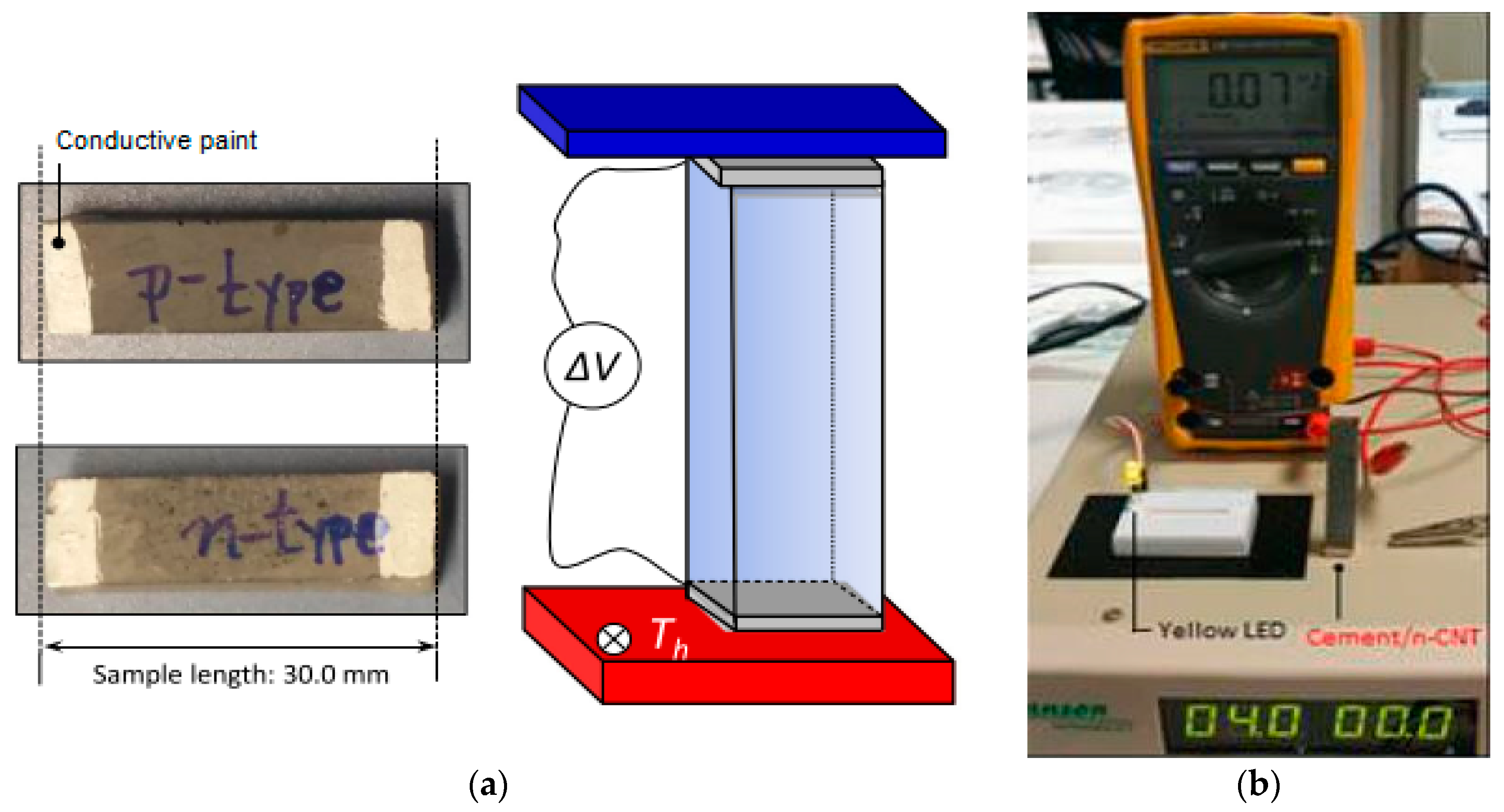
Figure 13 shows the test setup of some thermoelectric cementitious materials.
Figure 14 shows the maximum power output of road thermoelectric harvesters, or the measured figures of merit of cementitious thermoelectric samples, in one diagram.
2.3. Solar Panel Road Energy Harvester
Solar panels are well-known for converting solar radiation into electrical energy. They are compiled of several solar cells connected to each other in order to increase the electrical energy output of the whole panel. Solar cells are made of silicon-based crystals or, in more expensive types, made of scarcer materials such as gallium arsenide [
69]. Solar panels are widely used, especially in sun-catching environments and on residential buildings’ rooftops to generate off-grid electricity. The efficiency of these panels depends on a number of environmental factors, such as the weather conditions, as well as production factors, such as the type of solar cells and the surface area of the panel. Nowadays, they have versatile applications and even can be found on buildings’ rooftops for domestic energy generation. In addition to energy harvesting, one of the advantages of using solar panels on roads is the reduction of the urban heat island effect.
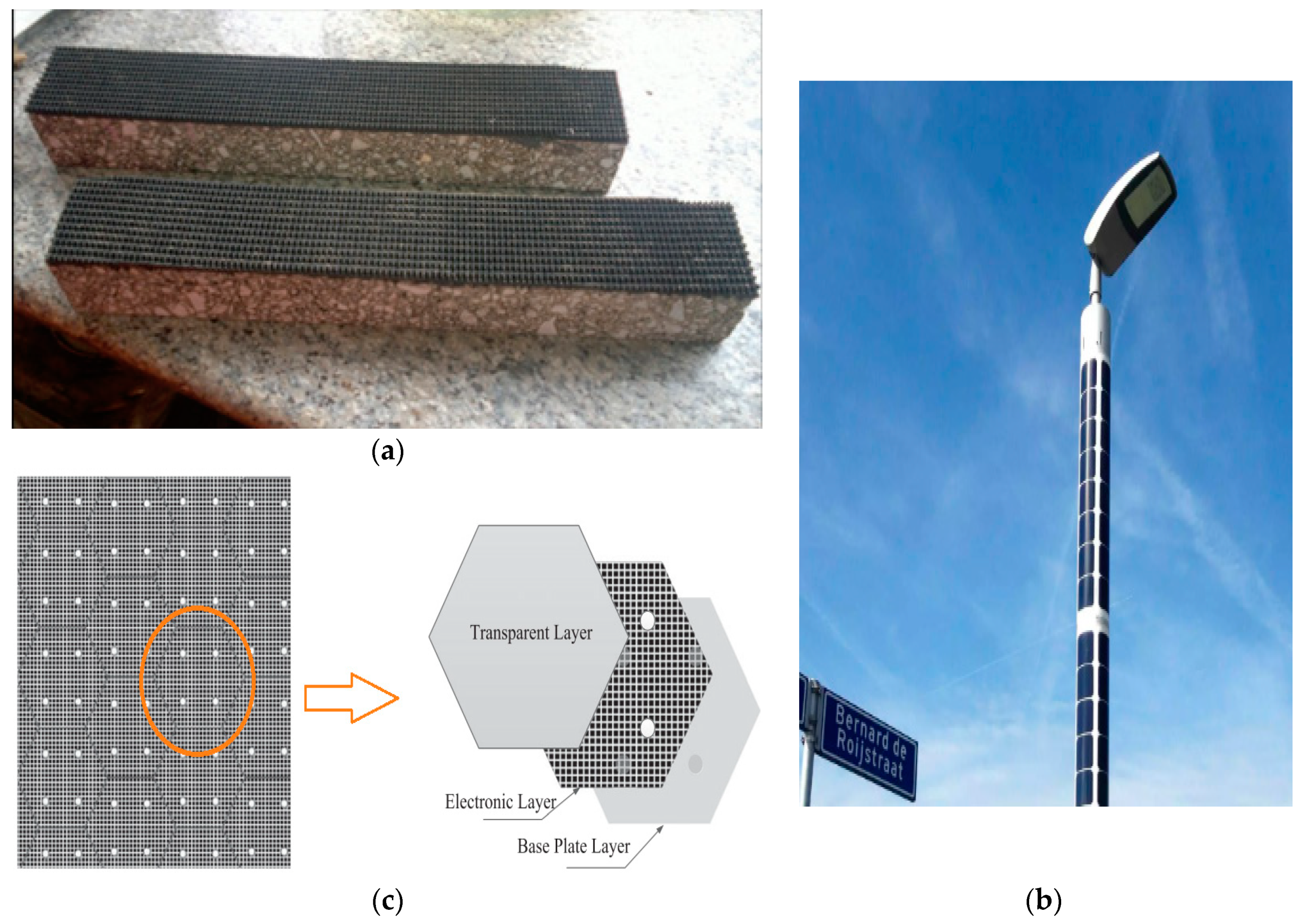
Implementing solar panels on roads or on road facilities has been investigated in some projects. In SolaRoad, solar panels were implemented on a biking lane pavement. In laboratory results, the output energy was almost 3 MW h over the first six months and the estimated energy density was 50–70 kWh per m² per year [
70].
Similarly, in other projects developed by Soluxio, flexible solar panels were formed in order to cover the surface of the lampposts in roads. The 4 to 12 m long cylindrical panels are installed around the lamppost, providing enough off-grid power to illuminate them. Each panel also consists of a microcontroller unit, to maximise the power, and lithium battery storage [
71]. However, it is noteworthy that these systems are associated with many challenges, such as protecting their fragile components, their dependence on the weather conditions and the partial shadow on them caused by the surroundings or by passing vehicles and, therefore, they are not easily compatible with the road conditions [
72,
73].
Figure 15 shows some examples of the mentioned solar panel applications on roads or on road facilities.
2.4. Electromagnetic Energy Harvesters
2.4.1. Electromagnetism
Electromagnetic generators are the core of the electromechanical conversion systems. They are used in several systems such as wind and water turbines. They consist of a coil rotor and a permanent magnet. Once the coil rotor has started rotation, it creates a time changing magnetic field, which accompanies an electric field, based on Faraday’s law [
76,
77]. The rate of change in the magnetic field has a direct relationship with the generated electric field:
where
is the Del operator,
E is the electric field,
B is the magnetic field and t is the time.
In addition to the generators, electromechanical harvesters also need an apparatus to capture the mechanical energy and convert it into a rotational movement. For example, wind turbines consist of large turbines rotating with the wind flow. In road energy harvesters, conversion of the road surface displacements is often done by devices such as hydraulic cylinders and rack and pinions [
78].
2.4.2. Experimental Studies on Road Electromagnetic Energy Harvesters
Harvesting energy from roads using electromagnetism is a relatively new approach in this field and is categorised as a mechanical system, converting the roads’ kinetic energy into electrical energy using electromagnetic generators. Depending on their energy transfer mechanism, these harvesters can be divided into rack and pinion, hydraulic and roller. Experimental and theoretical studies have been conducted on developing and testing each of these harvesting systems, some of which are discussed briefly in the following section.
Rack and Pinion Electromechanical Energy Harvester
In these harvesters, the vertical movement of the road surface is converted into a rotational movement through a rack and pinion system connected to the surface. These harvesters are usually developed within a speed bump structure.
In a recent study, Gholikhani et al. developed a speed bump system with a moving surface, which rotates a pinion by the connected rack. The pinion is then connected to a clutch to have unidirectional rotations. The preliminary results of the plain system resulted in a maximum power output of 1.96 mW; however, their following prototypes included a gearbox, which increased the number of rotations and hence the power output up to a maximum of almost 16 W [
79,
80,
81]. In another study, they evaluated the critical factors affecting the output of their harvester and identified the supports’ spring stiffness, loading and unloading and the magnitude of the load [
77].
In a prior study, Duarte et al. developed a similar system to be implemented in the regions of speed reduction (similar to speed bumps) [
82]. Instead of having vertical rack, their harvester was comprised of a double crank system hinged on the surface plate. Vertical displacement of the plate made the cranks move horizontally, spinning the pinions connected to the electromechanical converters. Their developed harvester was implemented in both pedestrian and road pavements [
82,
83,
84,
85].
Figure 16 shows two different mechanisms of mechanical road energy harvesters based on rack and pinion.
Hydraulic Electromechanical Energy Harvester
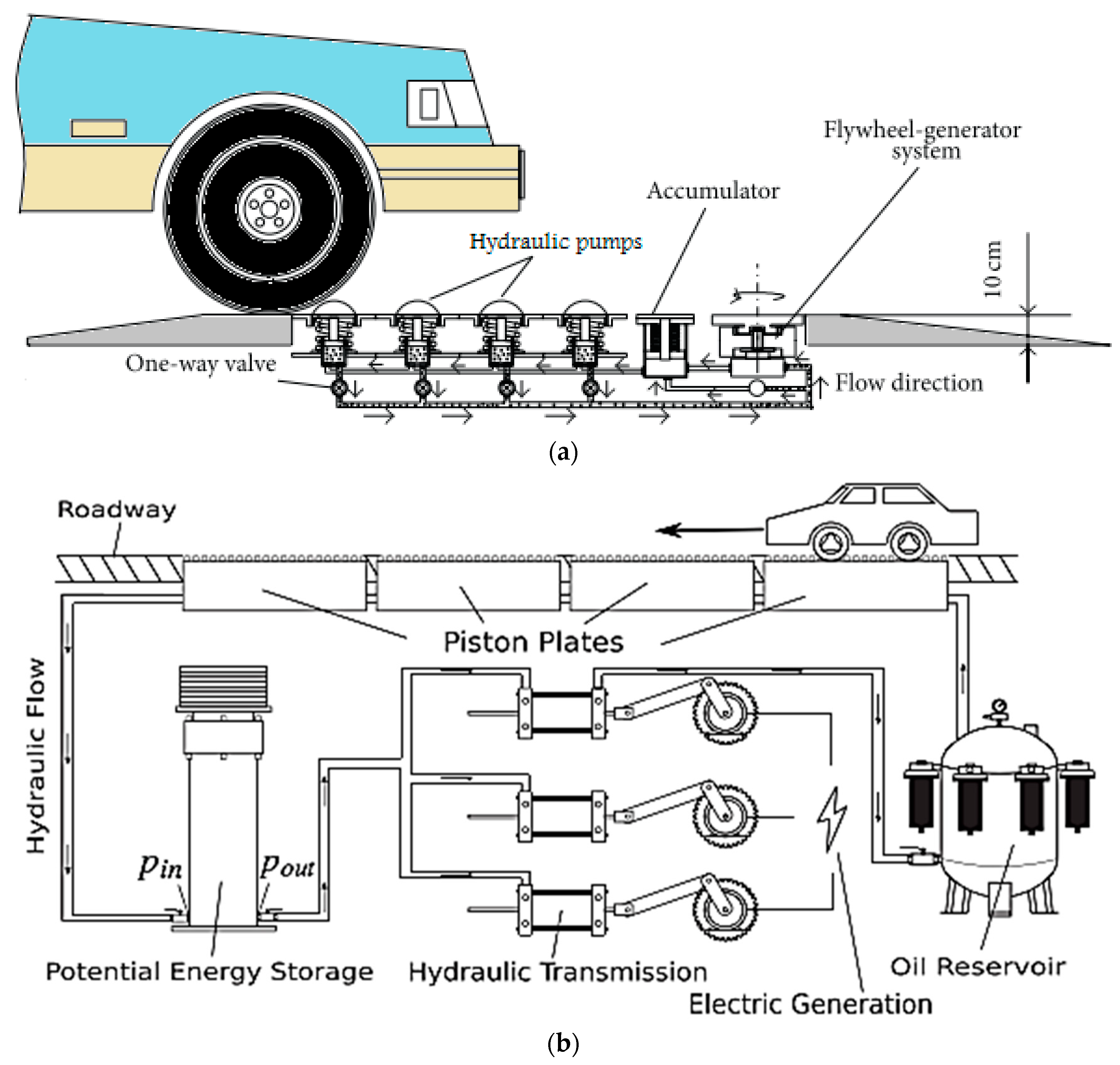
Unlike the rack and pinion system, in these harvesters, the load from the passing vehicles is transferred through a hydraulic medium to move a piston and spin the motor and the connected generator to generate power. Speed bumps are also considered a suitable host for these harvesters.
Ting et al. conducted one of the most prominent experimental studies of these systems. In their research, they developed a harvester specifically for downhill deceleration purposes. It is composed of several pistons with a stroke of 3 cm connected to a hydraulic potential energy collector and a generator. The collector’s role is to save energy in case the applied load is not enough to produce energy efficiently. The results show an average power output of almost 600 W and working efficiency of almost 41% for the system [
86]. A similar hydraulic system was developed and analysed, theoretically giving an output of efficiency of almost 68% [
87]. In 2017, a speed bump hybrid harvester was developed, combining a hydraulic collector and a crank and pinion system. Their theoretical analysis showed a similar power output over the first 24 h [
88].
A few other studies have employed the concept of the hydraulic harvester to develop an energy harvesting system using shock absorbers and vehicle suspensions. Li et al. designed a damper energy harvester using a hydraulic motor and a generator to produce electrical power. A maximum output of 435 W was obtained under 3 cm excitation and 0.8 Hz vibration [
89]. Another prototype with a similar concept resulted in an average power output of 34–100 W under various testing factors [
90]. Examples of mechanisms of hydraulic road energy harvesters are shown in
Figure 17.
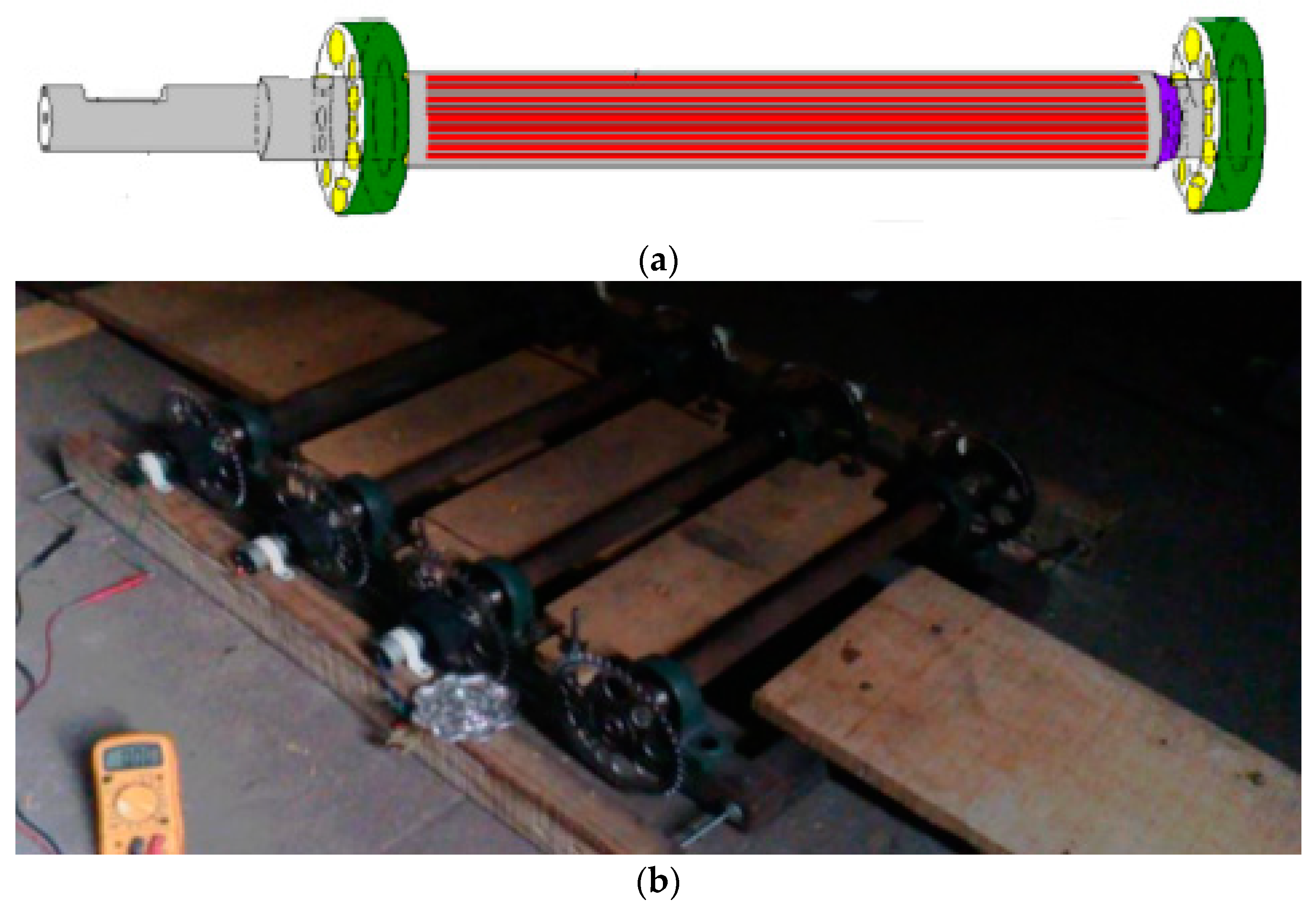
Roller Electromechanical Energy Harvester
These harvesters were designed as speed bumps placed across the roads, and once a car passes over them, due to friction, the roller rotates and spins a generator to produce electrical power [
92]. Sarma et al. designed a set of these harvesters and obtained 1.67 watts from only one motorbike vehicle passing [
93]. An illustration of a roller electromagnetic road harvester is shown in
Figure 18.
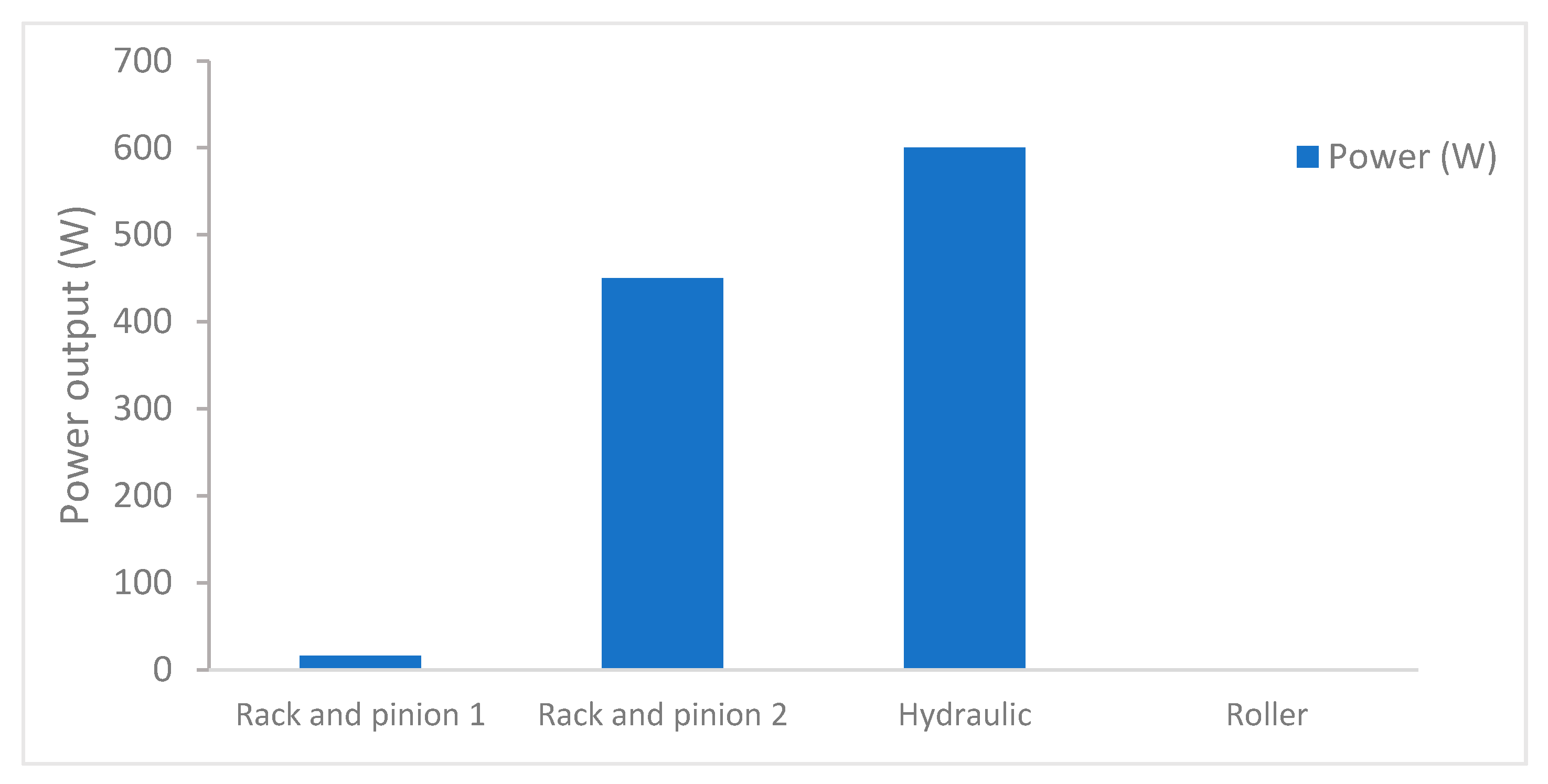
The power outputs of various mechanical road energy harvesters from different experimental studies have been plotted in
Figure 19.
3. Experimental Studies on Energy Storage Infrastructures
Energy storage is an essential phase of harvesting energy after the conversion phases. Some suggestions of energy storage for road energy harvesting systems include super capacitors, big batteries and hydraulic energy storage. In the latter case, the energy is stored in the form of mechanical hydraulic energy, which will be converted to electrical energy once a threshold is passed. These facilities are often additional components of energy harvesting systems, taking place either within the mechanical module or as a separate module by the side of the road.
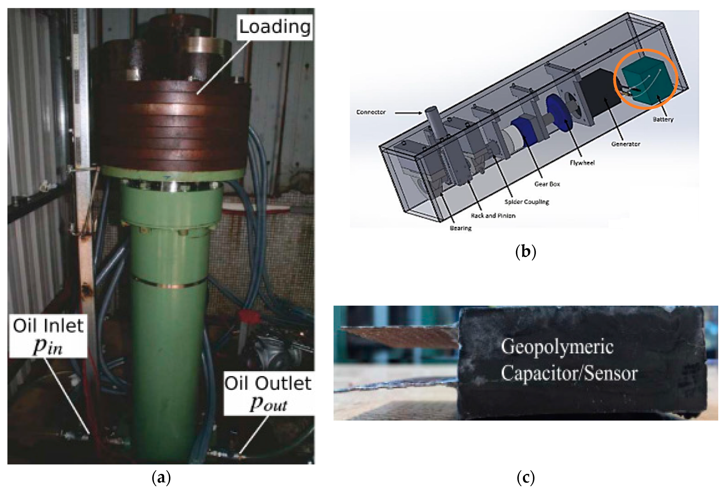
Figure 20 shows examples of these facilities from various references.
Moreover, a new approach addresses a crucial point about the existing energy storage infrastructure, which is to have components which are more mechanically compatible with the rest of the structure. In this regard, a newly developed approach is to build energy storage composites based on building materials and composites.
In a recent study, Saafi et al. developed and tested a potassium geopolymer cement paste capable of serving as a capacitor and sensor (
Figure 20). The power density of the paste was measured to be almost 0.33 kW/m
2, discharging in around 2 h. Based on density functional theory (DFT) simulations and experiments, the performance of this paste as a capacitor depends on the diffusion of cations of K and, therefore, when the effective thickness of the samples increases, there are more K+ ions in the matrix, making the sample work better [
95].
Moreover, Zhang et al. developed a structural super capacitor based on cement and graphene. Super capacitors were made by making thin sheets of cement paste with water to cement ratios starting from 0.3 up to 0.5. Once cured, they were sandwiched between the sheets of conductive graphene electrodes. The results showed that the samples’ specific capacitance peaks at a water to cement ratio equal to almost 0.4 and decreases after that and also as the hydration proceeds. The maximum capacity (almost 19.5 F/g) was seen for the samples with a 0.4 water to cement ratio at the age of three days [
96].
Meng et al. conducted one of the earlier works in this field. They developed a cement matrix-based battery, using manganese dioxide particles for the cathode, zinc for the anode electrode and carbon black dispersion in both as the conductive additive. The electrolyte of the battery is the pore solution in the cement paste, placed between the electrodes. The experimental results of this battery showed a 0.72 V open-circuit voltage, a maximum current of 120 μA and a highest power output density of 1.4 μW/cm
2 [
97].
Moreover, Adam et al. developed a thin-film capacitor ideal for light structures, with a specific capacitance of 35.98 µF/g, maintaining 1500 cycles of charging and discharging. In another study, a multifunctional energy storage laminated composite was built, giving a maximum specific capacity of almost 7.4 F/g [
98,
99,
100].
Compressed air energy storage (CAES) is another newly developed plan for storing and transferring energy on large scales. This system is usually adopted for wind turbine harvesters. However, considering the potentially large amounts of energy generated by electromagnetic road energy harvesters, this storage plan can also be a suitable match for these harvesters.
Figure 21 shows a schematic diagram of this system and an illustration of the storage plan.
4. Comparison of Energy Conversion Systems, Their Applications and Challenges
Considering the energy harvesting techniques discussed in the previous sections, one of the notable differences between them is their power output. Electromagnetic harvesters (apart from their medium) usually have high power output, ranging between almost 15 W and 600 W in different references. This power output is sufficient enough for powering street lighting, facilities and wireless connections. However, the application of this technology in roadways is limited because it influences the traffic flow, requires maintenance and is relatively new.
Piezoelectric energy harvesters are another method of harvesting energy from roads. Their power output is significantly lower than electromagnetic systems, and their fabrication and maintenance are relatively expensive. However, they can directly be placed in the pavement system (in a protective case), and, unlike some other methods, their performance is not dependent on the weather conditions. Although their power output is low, they can be utilised in remote sensors and systems which require micro-level power.
Thermoelectric and photovoltaic cell harvesters are also devices which can be installed in civil structures including road pavements for energy harvesting purposes. They are similar to each other in terms of being dependent on the weather conditions and the climate of the region, which limits their application. They also have low power output compared to electromagnetic systems. Both of them are usually easy to install and integrate into the road structure and are cheaper than piezoelectric harvesters. However, similar to piezoelectric harvesters, the power output of these harvesters is also low, which makes them suitable for low power sensors and devices.
Table 1 describes the positive and negative features of each studied technology.
4.1. Cost-Benefit and Technology Readiness Level Assessment (TRL)
Besides the advantages and disadvantages of each technology, technology readiness levels (TRL) and cost-benefit analysis are essential to classify and assess them. Originally developed and practiced by NASA for many years, TRL is a systematic measurement methodology used to appraise technologies’ maturity levels. It is categorised from 1, standing for having only the basic principles recognised and described, to 9, being fully developed, successfully tested and ready. The full description of each stage of TRL is shown in
Table 2 [
102,
103].
Moreover, cost-benefit analysis which financially evaluates the technologies is another useful method to classify and compare them. However, it is worth mentioning that most of these mechanisms are still in their development process. Hence, their full and detailed financial appraisal, considering their long-term performance and their interactions with other pavement facilities, is still not available. Still, estimated cost analyses have been prepared, considering the costs of building the unit and its installation in the testing environment, and it is compared with the cost of energy provided by the conventional power plants, which is, in the US, for each Kwh, between $ 0.15 and $ 0.30, ignoring the environmental costs.
Table 3 shows the TRL and cost-benefit (as described) analysis results of the developed road energy harvester units.
As reported in
Table 3, most of the energy harvesting technologies are still in the initial or median level of readiness, meaning that they are still in the development process. Most of them have not been installed or approved in their relevant environment (TRL < 5) and all of them generate more expensive power than fossil fuel power plants. It is worth mentioning that, although they produce more expensive power than conventional power plants, their power generation has less CO
2 emission, which is a remarkable improvement considering the environmental costs of energy generation. Therefore, future studies are still needed to fill this gap between the laboratory demonstration and their full operational mode in roads and eventually have more energy-efficient cities.
4.2. Road–Harvester Interaction Challenges
As mentioned previously, except for solar panels harvesters, none of the investigated technologies have been installed and performed on roads. However, in this section, considering the available harvesters from the literature, some future challenges have been recounted for each of them.
In the piezoelectric harvester developed by Jasim et al. [
3], the piezoelectric pieces have high mechanical properties (Young’s modulus = 63 GPa), which makes them a suitable option for bearing mechanical loads. However, these pieces are placed in a harvester module case, which is mostly a metallic box and eventually embedded in the depth of the road (almost 10 cm deep). While the elastic modulus of a mid-range aggregate asphalt pavement is 488.95 MPa [
106], the elastic modulus of aluminium (an alternative for the material of the case) is 69 GPa. This significant incompatibility between these materials, especially between the asphalt and the metallic case, makes them perform differently under mechanical loads. Some additional cracking and degradation will occur on the surface and depth of the roads under operation. These materials also have different thermal properties, which can trigger thermal cracks on the pavements as well. Moreover, in the long term, the modules will also need maintenance. For example, fatigue damages due to the cyclic loads from vehicles is a common reason for the piezoelectric pieces breaking down and failing, in which case the piece should be replaced. In addition, the modules’ insulation against moisture penetration is a critical matter, which has to be checked and maintained.
The thermoelectric road harvester which was developed by Datta et al. [
55] has a Z-shaped piece made of copper which is embedded 2 cm in the road. Similar to the discussion of piezoelectric harvesters, the difference between the mechanical and thermal properties of the asphalt and the copper piece could trigger some cracks and rupture in the pavement in the long term. Since the copper piece is placed by the side of the road, the thermal cracks are more critical than the mechanical ones. Moreover, the TEG ceramics, which are also used in this study, are fragile pieces and once they break, they should be replaced. Therefore, maintenance of these systems, and specifically the TEG components, is crucial. In addition, this system works based on the temperature difference. While the heat is planned to be provided from the hot surface of the pavement, the cold sink is provided by a tank filled with water installed at almost 20 cm depth in the road. The water in the tank needs constant monitoring for its temperature and occasional refilling. Compared to piezoelectric harvesters, this type of harvester has better insulation. However, it still needs monitoring for potential moisture leakage.
Solar pavements developed and implemented in the Solaroad project [
70] are the most developed technology, with a TRL of 9. In this project, exclusively designed solar panels are placed on the surface of the biking lane. Following the performance of this project reveals that the cracks appearing on the surface of the road are critical and need maintenance. Furthermore, as the project was extended to develop a Solaroad bus lane, due to the irreparable damage to the panels, the project was stopped.
Electromagnetic road energy harvesting systems are mainly developed as speed bumps, which are known facilities of roads, to increase safety. Therefore, they have an established form of interaction with the pavement, in terms of mechanical performance. As in the work by Todaria et al. [
94], the conversion and storage components of the system are all within the speed bump structure placed under the cap, and if one of these parts required repair, the whole system would be affected. The performance of the suspension system (springs and dampers) is crucial as it is constantly under dynamic loads. They need regular monitoring, especially for fatigue. The whole speed bump harvester should be monitored for corrosion or other erosive phenomena. Moreover, the speed bump structure should also be well-insulated, especially against moisture and liquid seepage.
5. Conclusions and Future Perspective
In this paper, the available technologies of energy harvesting from roads and their related infrastructures are summarised. Harvesting technologies of piezoelectric systems, thermoelectric systems, solar panels and electromagnetic modules have been explained, and the recent studies conducted on them have been discussed briefly. Moreover, to address the fundamental issue of energy resources which was initially mentioned, special attention was paid to the experimental and fieldwork outcomes of these works in terms of their efficiency and energy output. Accordingly, comparing the energy output of the systems, electromagnetic-based systems outperform the rest of the technologies significantly, by an average of least 15 W. Most of these electromagnetic harvesters were designed within the structure of road speed bumps, which are fundamental devices in roads to lower vehicle speeds and improve roads’ safety. Therefore, for future research, improving these systems in terms of their mechanical efficiency and their maintenance is recommended in order to develop more sustainable infrastructures.
Another promising topic in this field is developing building materials which are capable of energy harvesting. In particular, cement-based piezoelectric and thermoelectric and energy storing composites are recently developed topics which have high potential for further improvements and future applications. Although their power output is relatively negligible compared to electromagnetic systems, their high compatibility with their host environment (the same material) is a significant advantage over all other systems.
Finally, based on the TRL and cost-benefit analysis results, it is shown that most of these technologies are still in their laboratory demonstration stage, and their power generation is still more expensive compared to the economic cost of fossil fuel power generation. Future research is demanded in order to address these issues and develop and prepare these systems for actual real-field operations.
Author Contributions
Conceptualization, N.Z. and M.S.; investigation, N.Z.; writing—original draft preparation, N.Z.; writing—review and editing, N.Z. and M.S.; supervision, M.S.; project administration, M.S.; funding acquisition, M.S. All authors have read and agreed to the published version of the manuscript.
Funding
This research is funded by SAFERUP! from the European Union’s Horizon 2020 research and innovation program, under the Marie Skłodowska-Curie grant agreement no. 765057.
Acknowledgments
This project is affiliated with the SAFERUP! network, aiming to research “Sustainable, Accessible, Safe, Resilient, and Smart Urban Pavements”.
Conflicts of Interest
The authors declare no conflict of interest.
References
- Department of Business Energy and Industrial Strategy. UK Energy in Brief; BEIS: London, UK, 2018; pp. 1–52. [Google Scholar]
- Guo, L.; Lu, Q. Numerical analysis of a new piezoelectric-based energy harvesting pavement system: Lessons from laboratory-based and field-based simulations. Appl. Energy 2019. [Google Scholar] [CrossRef]
- Jasim, A.F.; Wang, H.; Yesner, G.; Safari, A.; Szary, P. Performance Analysis of Piezoelectric Energy Harvesting in Pavement: Laboratory Testing and Field Simulation. Transp. Res. Rec. 2019, 2673, 115–124. [Google Scholar] [CrossRef]
- Zhao, H.; Tao, Y.; Niu, Y.; Ling, J. Harvesting energy from asphalt pavement by piezoelectric generator. J. Wuhan Univ. Technol. Mater. Sci. Ed. 2014, 29, 933–937. [Google Scholar] [CrossRef]
- Duarte, F.; Ferreira, A. Energy harvesting on road pavements: State of the art. Proc. Inst. Civ. Eng. Energy 2016, 169, 79–90. [Google Scholar] [CrossRef]
- Guo, L.; Lu, Q. Potentials of piezoelectric and thermoelectric technologies for harvesting energy from pavements. Renew. Sustain. Energy Rev. 2017, 72, 761–773. [Google Scholar] [CrossRef]
- Paradiso, J.; Abler, C.; Hsiao, K.Y.; Reynolds, M. The magic carpet: Physical sensing for immersive environments. Conf. Hum. Factors Comput. Syst. Proc. 1997, 277–278. [Google Scholar] [CrossRef]
- Zhang, X.; Zhao, L.D. Thermoelectric materials: Energy conversion between heat and electricity. J. Mater. 2015, 1, 92–105. [Google Scholar] [CrossRef]
- Nandigam, K.; Chowdhury, B.H. Power flow and stability models for induction generators used in wind turbines. In Proceedings of the IEEE Power Engineering Society General Meeting, Denver, CO, USA, 6–10 June 2004; IEEE: Piscatvey, NJ, USA, 2004; pp. 2012–2016. [Google Scholar]
- Erturk, A.; Inman, D.J. Piezoelectric Energy Harvesting; John Wiley & Sons: Hoboken, NJ, USA, 2011; ISBN 1119991358. [Google Scholar]
- Xu, R.; Kim, S.-G. Figures of Merits of Piezoelectric Materials in Energy. PowerMEMS 2012, 464–467. [Google Scholar]
- Priya, S.; Song, H.-C.; Zhou, Y.; Varghese, R.; Chopra, A.; Kim, S.-G.; Kanno, I.; Wu, L.; Ha, D.S.; Ryu, J.; et al. A Review on Piezoelectric Energy Harvesting: Materials, Methods, and Circuits. Energy Harvest. Syst. 2017, 4, 3–39. [Google Scholar] [CrossRef]
- Kishore, R.A.; Priya, S. A Review on low-grade thermal energy harvesting: Materials, methods and devices. Materials (Basel) 2018, 11, 1433. [Google Scholar] [CrossRef]
- APC International, Ltd. Piezoelectric Ceramics: Principles and Applications; APC International: Mackeyville, PA, USA, 2002; ISBN 0971874409. [Google Scholar]
- Platt, S.R.; Farritor, S.; Haider, H. On Low-frequency electric power generation with PZT ceramics. IEEE/ASME Trans. Mechatron. 2005, 10, 240–252. [Google Scholar] [CrossRef]
- Li, H.; Tian, C.; Deng, Z.D. Energy harvesting from low frequency applications using piezoelectric materials. Appl. Phys. Rev. 2014, 1. [Google Scholar] [CrossRef]
- Xiong, H.; Weaver, E. Piezoelectric Energy Harvesting on Public Roadways. Int. J. Pavement Res. Technol. 2013, 5, 331–337. [Google Scholar]
- Lee, J.H.; Kim, J.; Kim, T.Y.; Al Hossain, M.S.; Kim, S.W.; Kim, J.H. All-in-one energy harvesting and storage devices. J. Mater. Chem. A 2016, 4, 7983–7999. [Google Scholar] [CrossRef]
- Roshani, H. Feasibility Study of Piezoelectric Energy Harvesting From; The University of Texas at San Antonio: San Antonio, TX, USA, 2016. [Google Scholar]
- Anton, S.R.; Sodano, H.A. A review of power harvesting using piezoelectric materials (2003–2006). Smart Mater. Struct. 2007, 16. [Google Scholar] [CrossRef]
- Song, Y.; Yang, C.H.; Hong, S.K.; Hwang, S.J.; Kim, J.H.; Choi, J.Y.; Ryu, S.K.; Sung, T.H. Road energy harvester designed as a macro-power source using the piezoelectric effect. Int. J. Hydrog. Energy 2016, 41, 12563–12568. [Google Scholar] [CrossRef]
- Liu, X.; Wang, J. Performance Exploration of A Radially Layered Cymbal Piezoelectric Energy Harvester under Road Traffic Induced Low Frequency Vibration. IOP Conf. Ser. Mater. Sci. Eng. 2019, 542, 012075. [Google Scholar] [CrossRef]
- ZHAO, H.; QIN, L.; LING, J. Test and Analysis of Bridge Transducers for Harvesting Energy from Asphalt Pavement. Int. J. Transp. Sci. Technol. 2015. [Google Scholar] [CrossRef]
- Palosaari, J.; Leinonen, M.; Hannu, J.; Juuti, J.; Jantunen, H. Energy harvesting with a cymbal type piezoelectric transducer from low frequency compression. J. Electroceramics 2012, 28, 214–219. [Google Scholar] [CrossRef]
- Khalili, M.; Biten, A.B.; Vishwakarma, G.; Ahmed, S.; Papagiannakis, A.T. Electro-mechanical characterization of a piezoelectric energy harvester. Appl. Energy 2019, 253, 113585. [Google Scholar] [CrossRef]
- Roshani, H.; Jagtap, P.; Dessouky, S.; Montoya, A.; Papagiannakis, A.T. Theoretical and experimental evaluation of two roadway piezoelectric-based energy harvesting prototypes. J. Mater. Civ. Eng. 2018, 30. [Google Scholar] [CrossRef]
- Xiong, H.; Wang, L. Piezoelectric energy harvester for public roadway: On-site installation and evaluation. Appl. Energy 2016, 174, 101–107. [Google Scholar] [CrossRef]
- Zhao, H.; Qin, L.; Tao, Y.; Ling, J. Study on structure of PZT piles based transducer for harvesting energy from asphalt pavement. In Proceedings of the 2013 IJPC-International Journal of Pavements Conference, São Paulo, Brazil, 9–10 December 2013; pp. 1–9. [Google Scholar]
- Roshani, H.; Dessouky, S.; Montoya, A.; Papagiannakis, A.T. Energy harvesting from asphalt pavement roadways vehicle-induced stresses: A feasibility study. Appl. Energy 2016, 182, 210–218. [Google Scholar] [CrossRef]
- Xu, T.B.; Siochi, E.J.; Kang, J.H.; Zuo, L.; Zhou, W.; Tang, X.; Jiang, X. Energy harvesting using a PZT ceramic multilayer stack. Smart Mater. Struct. 2013, 22. [Google Scholar] [CrossRef]
- Zhao, S.; Erturk, A. Deterministic and band-limited stochastic energy harvesting from uniaxial excitation of a multilayer piezoelectric stack. Sens. Actuators A Phys. 2014, 214, 58–65. [Google Scholar] [CrossRef]
- Jiang, X.Z.; Li, Y.C.; Wang, J.; Li, J.C. Electromechanical modeling and experimental analysis of a compression-based piezoelectric vibration energy harvester. Int. J. Smart Nano Mater. 2014, 5, 152–168. [Google Scholar] [CrossRef]
- Wang, C.; Song, Z.; Gao, Z.; Yu, G.; Wang, S. Preparation and performance research of stacked piezoelectric energy-harvesting units for pavements. Energy Build. 2019, 183, 581–591. [Google Scholar] [CrossRef]
- Fan, K.; Tan, Q.; Liu, H.; Zhu, Y.; Wang, W.; Zhang, D. Hybrid piezoelectric-electromagnetic energy harvester for scavenging energy from low-frequency excitations. Smart Mater. Struct. 2018, 27. [Google Scholar] [CrossRef]
- Chaipanich, A. Dielectric and piezoelectric properties of PZT-cement composites. Curr. Appl. Phys. 2007. [Google Scholar] [CrossRef]
- Chaipanich, A. Effect of PZT particle size on dielectric and piezoelectric properties of PZT-cement composites. Curr. Appl. Phys. 2007, 7, 574–577. [Google Scholar] [CrossRef]
- Sladek, J.; Novak, P.; Bishay, P.L.; Sladek, V. Effective properties of cement-based porous piezoelectric ceramic composites. Constr. Build. Mater. 2018, 190, 1208–1214. [Google Scholar] [CrossRef]
- Gong, H.; Zhang, Y.; Quan, J.; Che, S. Preparation and properties of cement based piezoelectric composites modified by CNTs. Curr. Appl. Phys. 2011, 11, 653–656. [Google Scholar] [CrossRef]
- Kumar, D.; Chaturvedi, P.; Jejurikar, N. Piezoelectric energy harvester design and power conditioning. In Proceedings of the 2014 IEEE Students’ Conference on Electrical, Electronics and Computer Science, Manit, Bhopal, 1–2 March 2014; pp. 1–6. [Google Scholar]
- Mishra, S.; Unnikrishnan, L.; Nayak, S.K.; Mohanty, S. Advances in Piezoelectric Polymer Composites for Energy Harvesting Applications: A Systematic Review. Macromol. Mater. Eng. 2019, 304, 1–25. [Google Scholar] [CrossRef]
- Yang, C.H.; Woo, M.S.; Song, Y.; Eom, J.H.; Kim, J.H.; Song, G.J.; Hong, S.K.; Sung, T.H.; Choi, J.Y.; Ryu, S.K. Development of impact-based piezoelectric road energy harvester for practical application. In Proceedings of the 2016 IEEE International Conference on Renewable Energy Research and Applications (ICRERA), Birmingham, UK, 20–23 November 2016; Volume 5, pp. 375–378. [Google Scholar]
- Zhang, H.; Huang, K.; Zhang, Z.; Xiang, T.; Quan, L. Piezoelectric Energy Harvesting From Roadways Based on Pavement Compatible Package. J. Appl. Mech. Trans. ASME 2019, 86. [Google Scholar] [CrossRef]
- Lee, H.; Jang, H.; Park, J.; Jeong, S.; Park, T.; Choi, S. Design of a Piezoelectric Energy-Harvesting shock absorber system for a vehicle. Integr. Ferroelectr. 2013, 141, 32–44. [Google Scholar] [CrossRef]
- Xiong, H.; Wang, L.; Wang, D.; Druta, C. Piezoelectric energy harvesting from traffic induced deformation of pavements. Int. J. Pavement Res. Technol. 2012, 5, 333–337. [Google Scholar]
- Rowe, D.M. Thermoelectrics Handbook; CRC/Taylor & Francis: Boca Raton, FL, USA, 2006; ISBN 9780849322648. [Google Scholar]
- Tritt, T.M.; Subramanian, M.A. T hermoelectric Materials, Phenomena, and Applications: A Bird’s Eye View. MRS Bull. 2006, 31, 188–198. [Google Scholar] [CrossRef]
- Lee, J.J.; Kim, D.H.; Lee, S.T.; Lim, J.K. Fundamental study of energy harvesting using thermoelectric effect on concrete structure in road. Adv. Mater. Res. 2014, 1044–1045, 332–337. [Google Scholar] [CrossRef]
- Weller, D.P.; Stevens, D.L.; Kunkel, G.E.; Ochs, A.M.; Holder, C.F.; Morelli, D.T.; Anderson, M.E. Thermoelectric Performance of Tetrahedrite Synthesized by a Modified Polyol Process. Chem. Mater. 2017, 29, 1656–1664. [Google Scholar] [CrossRef]
- Koumoto, K.; Funahashi, R.; Guilmeau, E.; Miyazaki, Y.; Weidenkaff, A.; Wang, Y.; Wan, C. Thermoelectric ceramics for energy harvesting. J. Am. Ceram. Soc. 2013, 96, 1–23. [Google Scholar] [CrossRef]
- Ruhul, M.; Bhuiyan, A.; Mamur, H. Bismuth Telluride (Bi2Te3) Nanostructure for Thermoelectric Applications. ISVOS J. 2019, 3, 1–7. [Google Scholar]
- Gostkowska, N.; Miruszewski, T.; Trawiński, B.; Bochentyn, B.; Kusz, B. Structure and thermoelectric properties of Cs-Bi-Te alloys fabricated by different routes of reduction of oxide reagents. Solid State Sci. 2017, 73, 41–50. [Google Scholar] [CrossRef]
- Tahami, S.A.; Gholikhani, M.; Nasouri, R.; Dessouky, S. Evaluation of a Novel Road Thermoelectric Generator System. MATEC Web Conf. 2019, 271, 08002. [Google Scholar] [CrossRef]
- Hasebe, M.; Kamikawa, Y.; Meiarashi, S. Thermoelectric generators using solar thermal energy in heated road pavement. In Proceedings of the 2006 25th International Conference on Thermoelectrics, Vienna, Austria, 6–10 August 2006; pp. 697–700. [Google Scholar]
- Jiang, W.; Yuan, D.; Xu, S.; Hu, H.; Xiao, J.; Sha, A.; Huang, Y. Energy harvesting from asphalt pavement using thermoelectric technology. Appl. Energy 2017, 205, 941–950. [Google Scholar] [CrossRef]
- Datta, U.; Dessouky, S.; Papagiannakis, A.T. Harvesting thermoelectric energy from asphalt pavements. Transp. Res. Rec. 2017, 2628, 12–22. [Google Scholar] [CrossRef]
- Wu, G.; Yu, X. Thermal Energy Harvesting System to Harvest Thermal Energy Across Pavement Structure. Int. J. Pavement Res. Technol. 2012, 5, 311–316. [Google Scholar]
- Park, P.; Choi, G.S.; Rohani, E.; Song, I. Optimization of thermoelectric system for pavement energy harvesting. Asph. Pavements 2014, 2, 1827–1838. [Google Scholar]
- Jiang, W.; Xiao, J.; Yuan, D.; Lu, H.; Xu, S.; Huang, Y. Design and experiment of thermoelectric asphalt pavements with power-generation and temperature-reduction functions. Energy Build. 2018, 169, 39–47. [Google Scholar] [CrossRef]
- Song, F.; Wu, L.; Liang, S. Giant Seebeck coefficient thermoelectric device of MnO2 powder. Nanotechnology 2012, 23. [Google Scholar] [CrossRef]
- Zuo, J.; Yao, W.; Liu, X.; Qin, J. Sensing properties of carbon nanotube–carbon fiber/cement nanocomposites. J. Test. Eval. 2012, 40, 838–843. [Google Scholar] [CrossRef]
- Ji, T.; Zhang, X.; Li, W. Enhanced thermoelectric effect of cement composite by addition of metallic oxide nanopowders for energy harvesting in buildings. Constr. Build. Mater. 2016, 115, 576–581. [Google Scholar] [CrossRef]
- Ghahari, S. The Effect of ZnO Nanoparticles on Thermoelectric Behavior and Fresh Properties of Cement Paste. Master’s Thesis, Purdue University, West Lafayette, IN, USA, 2016. [Google Scholar]
- Zuo, J.; Yao, W.; Wu, K. Seebeck effect and mechanical properties of carbon nanotube-carbon fiber/cement nanocomposites. Fuller. Nanotub. Carbon Nanostruct. 2015, 23, 383–391. [Google Scholar] [CrossRef]
- Tzounis, L.; Liebscher, M.; Fuge, R.; Leonhardt, A.; Mechtcherine, V. P- and n-type thermoelectric cement composites with CVD grown p- and n-doped carbon nanotubes: Demonstration of a structural thermoelectric generator. Energy Build. 2019, 191, 151–163. [Google Scholar] [CrossRef]
- Wei, J.; Zhang, Q.; Zhao, L.; Hao, L.; Yang, C. Enhanced thermoelectric properties of carbon fiber reinforced cement composites. Ceram. Int. 2016, 42, 11568–11573. [Google Scholar] [CrossRef]
- Wei, J.; Nie, Z.; He, G.; Hao, L.; Zhao, L.; Zhang, Q. Energy harvesting from solar irradiation in cities using the thermoelectric behavior of carbon fiber reinforced cement composites. RSC Adv. 2014, 4, 48128–48134. [Google Scholar] [CrossRef]
- Wei, J.; Zhang, Q.; Zhao, L.; Hao, L.; Nie, Z. Effect of moisture on the thermoelectric properties in expanded graphite/carbon fiber cement composites. Ceram. Int. 2017, 43, 10763–10769. [Google Scholar] [CrossRef]
- Wei, J.; Zhao, L.; Zhang, Q.; Nie, Z.; Hao, L. Enhanced thermoelectric properties of cement-based composites with expanded graphite for climate adaptation and large-scale energy harvesting. Energy Build. 2018, 159, 66–74. [Google Scholar] [CrossRef]
- Hanslmeier, A. The Ionosphere and Space Weather. Sun Space Weather 2002, 277, 169–192. [Google Scholar]
- SolaRoad. SolaRoad, the Road that Converts Sunlight into Electricity—SolaRoad is a Pioneering Innovation in the Field of Energy Harvesting, It is a Unique Concept, Which Converts Sunlight on the Road Surface into Electricity: The Road Network Works as an Inexha. Available online: https://www.solaroad.nl/wp-content/uploads/2015/10/SolaRoad_UK.pdf (accessed on 15 August 2020).
- FlexSol Solutions. Soluxio Catalogue 2019–2020. Available online: https://hubs.ly/H0f9QBh0 (accessed on 17 August 2020).
- Huang, X. A Future Energy Harvesting Scenario for Georgia Tech Campus Using Photovoltaic Solar Panels And Piezoelectric Materials. Master’s Thesis, Georgia Institute of Technology, Georgia, GA, USA, 2016. [Google Scholar]
- Selvaraju, R.K. Characterization of solar roadways via computational and experimental investigations. Master’s Thesis, The University of Western Ontario, Ontario, ON, Canada, 2012. [Google Scholar]
- Dezfooli, A.S.; Nejad, F.M.; Zakeri, H.; Kazemifard, S. Solar pavement: A new emerging technology. Sol. Energy 2017, 149, 272–284. [Google Scholar] [CrossRef]
- Ahmad, S.; Abdul Mujeebu, M.; Farooqi, M.A. Energy harvesting from pavements and roadways: A comprehensive review of technologies, materials, and challenges. Int. J. Energy Res. 2019, 43, 1974–2015. [Google Scholar] [CrossRef]
- Li, Z.; Yan, Z.; Luo, J.; Yang, Z. Performance comparison of electromagnetic energy harvesters based on magnet arrays of alternating polarity and configuration. Energy Convers. Manag. 2019, 179, 132–140. [Google Scholar] [CrossRef]
- Gholikhani, M.; Sharzehee, M.; Tahami, S.A.; Martinez, F.; Dessouky, S.; Walubita, L.F. Effect of electromagnetic energy harvesting technology on safety and low power generation in sustainable transportation: A feasibility study. Int. J. Sustain. Eng. 2019. [Google Scholar] [CrossRef]
- Gholikhani, M.; Roshani, H.; Dessouky, S.; Papagiannakis, A.T. A critical review of roadway energy harvesting technologies. Appl. Energy 2020, 261, 114388. [Google Scholar] [CrossRef]
- Gholikhani, M.; Nasouri, R.; Tahami, S.A.; Legette, S.; Dessouky, S.; Montoya, A. Harvesting kinetic energy from roadway pavement through an electromagnetic speed bump. Appl. Energy 2019, 250, 503–511. [Google Scholar] [CrossRef]
- Gholikhani, M.; Amid Tahami, S.; Dessouky, S. Harvesting Energy from Pavement—Electromagnetic Approach. MATEC Web Conf. 2019, 271, 06001. [Google Scholar] [CrossRef]
- Gholikhani, M.; Tahami, S.A.; Khalili, M.; Dessouky, S. Electromagnetic energy harvesting technology: Key to sustainability in transportation systems. Sustainability 2019, 11, 4906. [Google Scholar] [CrossRef]
- Duarte, F.J.A. Pavement Energy Harvesting System to Convert Vehicles Kinetic Energy into Electricity. Ph.D. Thesis, Universidade de Coimbra, Coimbra, Portugal, 2018. [Google Scholar]
- Duarte, F.; Ferreira, A.; Champalimaud, J.P. Waynergy People—Application in an operational environment. Proc. Inst. Civ. Eng. Energy 2018, 171, 82–89. [Google Scholar] [CrossRef]
- Duarte, F.; Casimiro, F.; Correia, D.; Mendes, R.; Ferreira, A. A new pavement energy harvest system. In Proceedings of the International Renewable and Sustainable Energy Conference, Ouarzazate, Morocco, 7–9 March 2013; pp. 408–413. [Google Scholar]
- Duarte, F.J.A.; FERREIRA, A.J.L.; FAEL, P.M.O. Device for Applying in a Pavement for Collecting Mechanical Energy from Vehicles Passing over for Generating Electricity 2020. U.S. Patent Application No. 16/489,080, 2 January 2020. [Google Scholar]
- Ting, C.C.; Tsai, D.Y.; Hsiao, C.C. Developing a mechanical roadway system for waste energy capture of vehicles and electric generation. Appl. Energy 2012, 92, 1–8. [Google Scholar] [CrossRef]
- Zhang, X.; Zhang, Z.; Meng, G.; Luo, D. Design, modeling, simulation of a novel mechanical road tunnel energy harvesting system with hydraulic transaction. In Proceedings of the 2015 IEEE International Conference on Information and Automation, Lijing, China, 8–10 August 2015; pp. 726–730. [Google Scholar]
- Ullah, K.M.; Ahsan-Uz-zaman, K.M.; Hosen, S.; Khan, R.H.; Parvin, S. Electrical power generation through speed breaker. In Proceedings of the 2016 9th International Conference on Electrical and Computer Engineering (ICECE), Barcelona, Spain, 7–11 December 2016; pp. 30–33. [Google Scholar]
- Li, C.; Tse, P.W. Fabrication and testing of an energy-harvesting hydraulic damper. Smart Mater. Struct. 2013, 22. [Google Scholar] [CrossRef]
- Gong, B.; Guo, X.; Hu, S.; Fang, Z. The ride comfort and energy-regenerative characteristics analysis of hydraulic-electricity energy regenerative suspension. J. Vibroengineering 2016, 18, 1765–1782. [Google Scholar]
- Hadi Obeid, H.; Jaleel, A.K.; Aubays Hassan, N. Design and Motion Modeling of an Electromagnetic Hydraulic Power Hump Harvester. Adv. Mech. Eng. 2014. [Google Scholar] [CrossRef]
- Ghuge, N.N.; Sathe, A.; Patil, V.; Warankar, A. Every Speed Breaker Is A Source Of Power. Int. J. Eng. Res. Appl. 2014, 4, 1–5. [Google Scholar]
- Sarma, B.S.; Jyothi, V.; Sudhir, D. Design of Power Generation Unit Using Roller Mechanism. IOSR J. Electr. Electron. Eng. 2014, 9, 55–60. [Google Scholar] [CrossRef]
- Todaria, P. Design, Modelling, and Test of an Electromagnetic Speed Bump Energy Harvester. Ph.D. Thesis, Virginia Tech, Virginia, VA, USA, April 2016. Available online: https://vtechworks.lib.vt.edu/handle/10919/73795 (accessed on 20 August 2020).
- Saafi, M.; Gullane, A.; Huang, B.; Sadeghi, H.; Ye, J.; Sadeghi, F. Inherently multifunctional geopolymeric cementitious composite as electrical energy storage and self-sensing structural material. Compos. Struct. 2018, 201, 766–778. [Google Scholar] [CrossRef]
- Zhang, J.; Xu, J.; Zhang, D. A Structural Supercapacitor Based on Graphene and Hardened Cement Paste. J. Electrochem. Soc. 2016, 163, E83–E87. [Google Scholar] [CrossRef]
- Meng, Q.; Chung, D.D.L. Battery in the form of a cement-matrix composite. Cem. Concr. Compos. 2010, 32, 829–839. [Google Scholar] [CrossRef]
- Adam, T.J.; Liao, G.; Petersen, J.; Geier, S.; Finke, B.; Wierach, P.; Kwade, A.; Wiedemann, M. Multifunctional composites for future energy storage in aerospace structures. Energies 2018, 11, 335. [Google Scholar] [CrossRef]
- Ladpli, P.; Nardari, R.; Kopsaftopoulos, F.; Wang, Y.; Chang, F.K. Design of multifunctional structural batteries with health monitoring capabilities. In Proceedings of the 8th European Workshop on Structural Health Monitoring (EWSHM 2016), Bilbao, Spain, 5–8 July 2016. [Google Scholar]
- Shirshova, N.; Qian, H.; Houllé, M.; Steinke, J.H.G.; Kucernak, A.R.J.; Fontana, Q.P.V.; Greenhalgh, E.S.; Bismarck, A.; Shaffer, M.S.P. Multifunctional structural energy storage composite supercapacitors. Faraday Discuss. 2014, 172, 81–103. [Google Scholar] [CrossRef]
- Kere, A.; Goetz, V.; Py, X.; Olives, R.; Sadiki, N.; Mercier, E. Dynamic behavior of a sensible-heat based thermal energy storage. Energy Procedia 2014, 49, 830–839. [Google Scholar] [CrossRef]
- Clausing, D.; Holmes, M. Technology readiness. Res. Technol. Manag. 2010, 53, 52–59. [Google Scholar] [CrossRef]
- European Commission. Horizon 2020—Work Programme 2014–2015 General Annexes—Annex G. Technology Readiness Levels (TRL). 2014, p. 4995. Available online: https://ec.europa.eu/research/participants/data/ref/h2020/wp/2014_2015/main/h2020-wp1415-intro_en.pdf (accessed on 20 August 2020).
- Guo, L.; Lu, Q. Modeling a new energy harvesting pavement system with experimental verification. Appl. Energy 2017, 208, 1071–1082. [Google Scholar] [CrossRef]
- Hossain, M.F.T.; Dessouky, S. Development of a Solar Prototype for Roadway. In MATEC Web of Conferences; EDP Sciences: Les Ulis, France, 2019; Volume 271, p. 08007. [Google Scholar] [CrossRef]
- Setiawan, A.; Suparma, L.B.; Mulyono, A.T. Developing the elastic modulus measurement of asphalt concrete using the compressive strength test. In AIP Conference Proceedings; AIP Publishing LLC: Melville, NY, USA, 2017; Volume 1903, p. 050002. [Google Scholar] [CrossRef]
© 2020 by the authors. Licensee MDPI, Basel, Switzerland. This article is an open access article distributed under the terms and conditions of the Creative Commons Attribution (CC BY) license (http://creativecommons.org/licenses/by/4.0/).


